WO2012144266A1 - 医用画像表示装置、医用画像表示方法 - Google Patents
医用画像表示装置、医用画像表示方法 Download PDFInfo
- Publication number
- WO2012144266A1 WO2012144266A1 PCT/JP2012/054271 JP2012054271W WO2012144266A1 WO 2012144266 A1 WO2012144266 A1 WO 2012144266A1 JP 2012054271 W JP2012054271 W JP 2012054271W WO 2012144266 A1 WO2012144266 A1 WO 2012144266A1
- Authority
- WO
- WIPO (PCT)
- Prior art keywords
- region
- interest
- pixel value
- adjacent
- projection line
- Prior art date
- Legal status (The legal status is an assumption and is not a legal conclusion. Google has not performed a legal analysis and makes no representation as to the accuracy of the status listed.)
- Ceased
Links
Images



Classifications
-
- G—PHYSICS
- G06—COMPUTING OR CALCULATING; COUNTING
- G06T—IMAGE DATA PROCESSING OR GENERATION, IN GENERAL
- G06T7/00—Image analysis
- G06T7/0002—Inspection of images, e.g. flaw detection
- G06T7/0012—Biomedical image inspection
-
- A—HUMAN NECESSITIES
- A61—MEDICAL OR VETERINARY SCIENCE; HYGIENE
- A61B—DIAGNOSIS; SURGERY; IDENTIFICATION
- A61B5/00—Measuring for diagnostic purposes; Identification of persons
- A61B5/0033—Features or image-related aspects of imaging apparatus, e.g. for MRI, optical tomography or impedance tomography apparatus; Arrangements of imaging apparatus in a room
-
- A—HUMAN NECESSITIES
- A61—MEDICAL OR VETERINARY SCIENCE; HYGIENE
- A61B—DIAGNOSIS; SURGERY; IDENTIFICATION
- A61B5/00—Measuring for diagnostic purposes; Identification of persons
- A61B5/74—Details of notification to user or communication with user or patient; User input means
- A61B5/742—Details of notification to user or communication with user or patient; User input means using visual displays
-
- A—HUMAN NECESSITIES
- A61—MEDICAL OR VETERINARY SCIENCE; HYGIENE
- A61B—DIAGNOSIS; SURGERY; IDENTIFICATION
- A61B5/00—Measuring for diagnostic purposes; Identification of persons
- A61B5/74—Details of notification to user or communication with user or patient; User input means
- A61B5/7475—User input or interface means, e.g. keyboard, pointing device, joystick
- A61B5/748—Selection of a region of interest, e.g. using a graphics tablet
-
- A—HUMAN NECESSITIES
- A61—MEDICAL OR VETERINARY SCIENCE; HYGIENE
- A61B—DIAGNOSIS; SURGERY; IDENTIFICATION
- A61B6/00—Apparatus or devices for radiation diagnosis; Apparatus or devices for radiation diagnosis combined with radiation therapy equipment
- A61B6/02—Arrangements for diagnosis sequentially in different planes; Stereoscopic radiation diagnosis
- A61B6/03—Computed tomography [CT]
-
- A—HUMAN NECESSITIES
- A61—MEDICAL OR VETERINARY SCIENCE; HYGIENE
- A61B—DIAGNOSIS; SURGERY; IDENTIFICATION
- A61B6/00—Apparatus or devices for radiation diagnosis; Apparatus or devices for radiation diagnosis combined with radiation therapy equipment
- A61B6/46—Arrangements for interfacing with the operator or the patient
- A61B6/461—Displaying means of special interest
- A61B6/466—Displaying means of special interest adapted to display 3D data
Definitions
- the present invention relates to a medical image display device that displays a medical image obtained from a medical image diagnostic apparatus including an X-ray CT apparatus, an MRI apparatus, an ultrasonic apparatus, and a nuclear medicine diagnostic apparatus. More specifically, the present invention extracts a luminal organ and a region around the luminal organ, and displays position information, shape information, image density information, composition information of the region around the luminal organ, and the like. The present invention relates to a medical image display device and the like.
- Patent Document 2 describes that information regarding depth is superimposed on an X-ray fluoroscopic projection image displayed as a guide image at the time of PCI (Percutaneous Coronary Intervention) treatment. Has been.
- the present invention has been made in view of the above-described problems, and an object thereof is to provide a medical image display technique that sufficiently displays information necessary for diagnosis and supports a diagnosis without oversight in a short time. It is to be.
- the first invention is a region of interest in which a first region of interest that is an observation region in volume data and a second region of interest that is a region of a lesion candidate related to the observation region are set.
- the pixel having the reference pixel value on the target projection line is a pixel of the first region of interest
- the setting unit and the adjacent second that is the second region of interest adjacent to the first region of interest on the target projection line
- a medical image display device comprising: a display image creation unit that creates a display image in which the size of a region of interest can be identified; and a display unit that displays the display image.
- a second invention includes a region-of-interest setting step of setting a first region of interest that is a region of an observation site in volume data and a second region of interest that is a region of a lesion candidate related to the observation site;
- the pixel having the reference pixel value is the pixel of the first region of interest
- the size of the adjacent second region of interest that is the second region of interest adjacent to the first region of interest on the target projection line is identified.
- It is a medical image display method including a display image creation step of creating a display image that can be displayed, and a display step of displaying the display image.
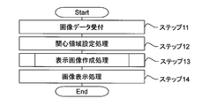
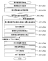
- Hardware configuration diagram of medical image display device The flowchart which shows the outline
- Schematic diagram for explaining the region of interest search process adjacent to the maximum pixel value existence region An example of a display image in the first embodiment
- the flowchart which shows the display image creation process in 2nd Embodiment An example of a display image in the second embodiment
- Flowchart showing display image creation processing in the fourth embodiment An example of a two-dimensional color map
- a controller 12, a keyboard 14, a main memory 15, a magnetic disk 16, and a display memory 17 are connected to a CPU 11 via a data transfer bus 19 so as to be able to send and receive signals.
- the CPU 11 is also connected to the medical imaging apparatus 20 via a data transfer bus 19 and a local area network (LAN) 21 so as to be able to send and receive signals.
- a mouse 13 is connected to the controller 12 so as to be able to send and receive signals.
- a display 18 is connected to the display memory 17 so that signals can be transmitted and received.
- “to enable signal transmission / reception” indicates a state in which signals can be transmitted / received to each other or from one to the other, regardless of whether they are electrically or optically wired or wireless.
- the CPU 11 executes a computer program and controls each connected element.
- the computer program can, for example, extract a luminal organ region included in medical image data, extract a region corresponding to a candidate lesion (such as plaque) in and around the luminal organ, and extract other organ regions around the luminal organ region. This is a command to the CPU 11 combined so that execution results such as extraction and creation of a display image based on the extracted area information can be obtained.
- the controller 12 transmits various data such as position displacement data obtained by a sensor provided on the mouse 13 and input data of button switches provided on the mouse 13 to the CPU 11 via the data transfer bus 19.
- the mouse 13 supports input of data by the operator. When the operator moves the cursor of the mouse 13 to an image displayed on the display 18 or a switch made by software such as a radio switch and clicks the position of the movement destination, predetermined input data is transmitted to the CPU 11.
- the keyboard 14 is an input device mainly used for character input such as ID information for specifying a medical image to be read from the magnetic disk 16 and a diagnostic report of a medical image displayed on the display 18.
- the main memory 15 is used as a work area for the CPU 11 such as loading various computer programs from the magnetic disk 16 and storing medical image data and the progress of computations when the CPU 11 executes the various computer programs.
- the magnetic disk 16 stores various computer programs. Further, the magnetic disk 16 receives and stores the tomographic image of the subject imaged by the medical image imaging device 20 via the LAN 21 and the data transfer bus 19.
- the magnetic disk 16 is an example of an external storage device in a computer system.
- the external storage device includes all storage media such as a flexible disk, an optical (magnetic) disk, a ZIP memory, and a USB memory.
- the display memory 17 temporarily stores data to be displayed on the screen among the calculation results of the CPU 11 before signal transfer to the display 18.
- the display 18 displays the medical image signal transferred from the display memory 17 and various information attached thereto.
- the data transfer bus 19 performs data transfer between elements connected to the data transfer bus 19.
- the medical imaging apparatus 20 can obtain a tomographic image of a subject such as an X-ray CT apparatus, an MRI apparatus, an ultrasonic apparatus, a scintillation camera apparatus, a PET apparatus, and a SPECT apparatus.
- the LAN 21 connects the medical image capturing apparatus 20 and the medical image display apparatus 1 so as to be able to send and receive signals. Note that a public line such as the Internet may be used instead of the LAN 21.
- the display 18 as a display device and the mouse 13 and the keyboard 14 as input devices are separated, but the display device and the input device may be integrated as a touch panel display or the like. .
- the medical image capturing apparatus 20 is not limited to the X-ray CT apparatus.
- the organ to be observed is not limited to the heart and coronary arteries, and may be other organs such as blood vessels and bronchi other than the coronary arteries.
- the operator operates input devices such as a mouse 13 and a keyboard 14 to select volume data to be observed from a volume data group captured by the medical image capturing apparatus 20.
- the CPU 11 of the medical image display apparatus 1 accepts the selected volume data (step 11).
- the CPU 11 performs a region of interest setting process (step 12).
- the CPU 11 extracts a heart region, a blood vessel / coronary artery region, and a plaque region around the blood vessel / coronary artery region, which are observation target organs of the present embodiment, from the received volume data, and sets the extracted region as a region of interest.
- each region of interest is set so that it can be identified whether it is a heart region, a blood vessel / coronary artery region, or a plaque region around the blood vessel / coronary artery region.
- the CPU 11 extracts a region by threshold processing using pixel value information such as a CT value.
- the CT value of a blood vessel / coronary artery into which a contrast agent has been injected and the CT value of a plaque existing around the blood vessel / coronary artery are greatly different. Therefore, the CPU 11 can easily distinguish the blood vessel / coronary artery region from the plaque region around the blood vessel / coronary artery region.
- the threshold value in the threshold processing is appropriately changed according to the imaging method.
- the CPU 11 is based on the designated position information. An area may be extracted.
- the CPU 11 sets the three regions of the heart region, the blood vessel / coronary artery region, and the plaque region around the blood vessel / coronary artery region as the region of interest.
- the region of interest to be set is not limited to this example.
- the CPU 11 may set at least the region of the observation site (for example, the blood vessel / coronary artery region) and the region of the lesion candidate related to the observation site (for example, the plaque region around the blood vessel / coronary artery region) in the volume data.
- the CPU 11 performs display image creation processing (step 13).
- the CPU 11 creates a display image based on the region of interest set in step 12. For example, when the pixel having the reference pixel value on the target projection line is a pixel in the observation region, the CPU 11 displays a display image that can identify the size of the lesion candidate region adjacent to the observation region. create.
- the reference pixel value is, for example, a maximum pixel value on the target projection line, a minimum pixel value on the target projection line, a pixel value closest to a predetermined pixel value on the target projection line, or the like.
- the reference pixel value is the maximum pixel value on the target projection line.
- MIP Maximum Intensity Projection
- MINIP Minimum Intensity Projection
- the CPU 11 performs image display processing (step 14).
- the CPU 11 displays the display image created in step 13 on the display 18 via the display memory 17.
- the CPU 11 may display only a display image viewed from a certain projection direction.
- the CPU 11 may simultaneously display display images viewed from a plurality of preset projection directions. Or you may make it CPU11 display the display image seen from several preset projection directions temporally continuously. In the present invention, as will be described later, it is possible to sufficiently display information necessary for diagnosis even with only one display image.
- the CPU 11 of the medical image display apparatus 1 in the display image creation process of step 13 lesion candidates (plaque etc.) adjacent to the distance (blood vessel diameter) of the region of the observation site (blood vessels, coronary arteries, etc.)
- a projection pixel value is set using the distance of the area, and a display image is created. More specifically, when the pixel having the reference pixel value on the target projection line is a pixel in the observation region, the CPU 11 determines a weighting factor according to the size of the adjacent lesion candidate region on the target projection line.
- the pixel value based on the pixel group of the adjacent lesion candidate region on the target projection line and the value obtained by weighting the reference pixel value on the target projection line with the weighting coefficient are set as the projection pixel value for the target projection line.
- the CPU 11 determines the weighting coefficient based on the number of pixels in the adjacent lesion candidate area on the target projection line and the number of pixels in the observation region including the reference pixel value on the target projection line.
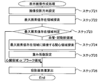
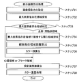
- the CPU 11 of the medical image display apparatus 1 performs an image projection direction setting process (step 21).
- the image projection direction setting process will be described with reference to FIG.
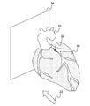
- FIG. 4 shows the region of interest set in step 12.
- a heart region 30, a blood vessel / coronary artery region 31, and a plaque region 32 are shown as regions of interest.
- the CPU 11 sets the projection direction 33 and the projection plane 34 according to the instruction.
- the projection plane 34 is set for each projection direction perpendicular to the designated projection direction 33.
- the operator may input a projection angle that defines the projection direction 33 by operating the mouse 13, the keyboard 14, or the like. Further, the operator may specify the projection direction and the direction of the projection plane while rotating by a drag operation using the mouse 13.
- the CPU 11 may set a projection angle that is determined empirically in advance.
- the projection angle can be defined by, for example, an azimuth angle indicating a horizontal angle and an elevation angle indicating an angle in the vertical direction (an upward angle is an elevation angle and a downward angle is a depression angle).
- the projection direction 33 may be set to only one direction as shown in FIG. 4, or a plurality of directions may be set.
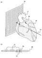
- FIG. 5A is an explanatory diagram for explaining the projection plane and the projection direction
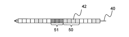
- FIG. 5B is a diagram showing a pixel group extracted along the projection direction.
- the CPU 11 sets a projection line 40 for each pixel on the projection plane 34 according to the direction of the projection direction 33.
- the projection method may be perspective projection or parallel projection.
- perspective projection it is possible to obtain the same projected image as that seen by a human.
- parallel projection since the projection lines are parallel to each other, the processing performed by the CPU 11 can be simplified.
- the projection line 40 includes a plurality of pixels 41 of the region of interest set in step 12.
- the CPU 11 searches for a pixel 42 having the maximum pixel value I C (hereinafter referred to as “maximum pixel value pixel 42”) from among the plurality of pixels 41 of the region of interest. Then, the CPU 11 specifies a region of interest 43 including the maximum pixel value pixel 42 (hereinafter referred to as “maximum pixel value existence region 50”).
- the maximum pixel value existence region 50 is any one of the heart region 30, the blood vessel / coronary artery region 31, and the plaque region 32 which are the regions of interest set in step 12.
- the CPU 11 performs a maximum pixel value existence area determination process (step 23).
- the CPU 11 determines whether the maximum pixel value existence region 50 identified in step 22 is the heart region 30, the blood vessel / coronary artery region 31, or the plaque region 32.
- the process proceeds to step 24, and in the case of the heart region 30 or plaque region 32 that is the other region (“23” in step 23).
- Heart region or plaque region ") go to step 26.
- the CPU 11 When the maximum pixel value existence region 50 is the blood vessel / coronary artery region 31 (the “blood vessel / coronary artery region” in step 23), the CPU 11 performs a region of interest search process adjacent to the maximum pixel value existence region (step 23). 24).
- the region-of-interest search process adjacent to the maximum pixel value existence region will be described with reference to FIG.
- the CPU 11 when there is a region of interest adjacent to the maximum pixel value existence region 50, the CPU 11 includes the region 51 (hereinafter referred to as “adjacent region of interest 51”) as the heart region 30 and the plaque region. 32 areas are specified.
- the adjacent region of interest 51 exists only on the back side (left side in FIG. 6) with respect to the projection direction of the projection line 40.
- the adjacent region of interest 51 exists only on the front side (right side in FIG. 6) with respect to the projection direction of the projection line 40 and on both the back side and the near side. Cases are also conceivable.
- the CPU 11 specifies the adjacent region of interest 51 as in the case where it exists only on the back side.
- the CPU 11 combines them as the adjacent region of interest 51 if both are the same region of interest (for example, both are the plaque region 32). Identify.
- the adjacent region of interest 51 exists on both the back side and the near side, the CPU 11 prioritizes the plaque region 32 if the regions of interest are different from each other (for example, the heart region 30 and the plaque region 32). The region of interest 51 is specified.
- the CPU 11 performs a weighting coefficient setting process (step 25).
- the CPU 11 calculates the number of pixels N C as the distance in the projection direction of the maximum pixel value existence region 50 on the projection line 40.
- CPU 11 is adjacent the region of interest 51 on the projection line 40, calculates the number of pixels N P as the distance of the projection direction.
- the adjacent region of interest 51 is a region other than the lesion candidate region, that is, the heart region 30 or the blood vessel / coronary artery region 31
- the weight coefficient W C corresponding to the maximum pixel value existing area 50, and the weight coefficient W P corresponding to adjacent ROI 51 is set as follows.
- the CPU 11 performs a projection pixel value calculation process (step 26).
- the maximum pixel value existence region 50 is a region other than the observation region (here, the heart region 30 or the plaque region 32)
- the CPU 11 uses the maximum pixel value I C specified in step 22 as the projection pixel value of the projection line 40.
- the maximum pixel value existence region 50 is the observation region (here, the blood vessel / coronary artery region 31)
- the CPU 11 uses the weighting coefficient calculated according to the equations (1) and (2) to The projection pixel value of the street projection line 40 is set.
- I C is the largest pixel value in the entire projection line 40.
- I P is the maximum pixel value, minimum pixel value, average pixel value, etc. of the adjacent region of interest 51 on the projection line 40.
- the CPU 11 executes the processing of Step 22 to Step 26 for all the pixels on the projection plane 34, that is, all the projection lines 40, thereby creating a display image.
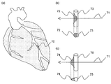
- FIG. 7A shows an example of a display image created according to the first embodiment.
- FIGS. 7B and 7C are enlarged views of the portion 60 in FIG. 7 (b) and 7 (c), a schematic perspective view of the blood vessels / coronary arteries 63 and 65 related to the region 60, and a schematic cross-sectional view of the blood vessels / coronary arteries 63 and 65 (the cross section shows the projection line 61). Included).
- the eccentric plaques 62 and 64 exist in the direction along the projection line 61 (the depth direction of the display image), they are created by the conventional maximum pixel value projection method.
- the pixel values corresponding to the blood vessels / coronary arteries 63 and 65 are displayed as they are, and therefore the presence of the eccentric plaques 62 and 64 may not be reflected on the image.
- the position where the eccentric plaques 62 and 64 exist adjacent to the blood vessel / coronary artery 63 is reflected in the blood vessel / coronary artery 63 where the pixel value decreases.
- the pixel value at the position where the eccentric plaque 62 is adjacent to the pixel value of the neighboring pixels is significantly reduced. This is because the distance (number of pixels) on the projection line 61 of the blood vessel / coronary artery 63 is shorter than the distance (number of pixels) on the projection line 61 of the adjacent eccentric plaque 62, and is calculated according to Equation (3). This is because the projected pixel value I of the projected line 61 is extremely small.
- the pixels in the observation region, where the pixel value is significantly lower than the pixel values of the surrounding pixels are abnormalities of the type in which the blood vessels are narrowed. It can be said that there is a high possibility.
- the decrease in the pixel value at the position where the eccentric plaque 62 is adjacent to the pixel value of the surrounding pixels is moderate. This is because the distance (number of pixels) on the projection line 61 of the blood vessel / coronary artery 65 is longer than the distance (number of pixels) on the projection line 61 of the adjacent eccentric plaque 62, and is calculated according to Equation (3). This is because the projected pixel value I of the projected line 61 is not extremely small. As can be seen from FIG.
- the medical image display apparatus sets the first region of interest that is the observation region in the volume data and the second region of interest that is the region of the lesion candidate related to the observation region. If the region of interest setting unit and the pixel having the reference pixel value on the target projection line are the pixels of the first region of interest, the adjacent region that is the second region of interest adjacent to the first region of interest on the target projection line A display image creating unit that creates a display image in which the size of the second region of interest can be identified; and a display unit that displays the display image.
- the display image creation unit determines a weighting factor according to the size of the adjacent second region of interest.
- a value obtained by weighting the pixel value based on the pixel group of the adjacent second region of interest and the reference pixel value on the target projection line by the weighting factor may be set as the projection pixel value for the target projection line.
- the display image creation unit may determine the weighting factor based on the number of pixels of the adjacent second region of interest and the number of pixels of the first region of interest including the reference pixel value.
- information based on the presence / absence and location of a lesion candidate, and the shape of a luminal organ and its surrounding area can be reflected on a single display image. Therefore, it is possible to display information necessary for diagnosis sufficiently and assist in making a diagnosis without oversight in a short time.
- the position where the lesion candidate exists is reflected in the image as a location where the pixel value decreases in the luminal organ.
- information based on the shape of the luminal organ and the surrounding area is reflected as a difference in the degree of decrease in the pixel value.
- I P in the formula (3) the maximum pixel value of the neighboring region of interest 51 on the projection line 40, the minimum pixel value, which is either such average pixel value.
- I C in Expression (3) is the largest pixel value in the entire projection line 40 identified in Step 22
- I P in Expression (3) is the projection line 40.
- the minimum pixel value or average pixel value of the upper adjacent region of interest 51 is desirable. That is, when the reference pixel value is the maximum pixel value of the target projection line is CPU 11 is an average pixel value or the minimum pixel value of the adjacent area of interest of the target projected line are substituted into the I P in equation (3), the projection It is desirable to set the pixel value.
- the difference between the pixel value of the pixel in which the lesion candidate exists and the pixel value of the pixel in the surrounding observation region increases, and the position of the lesion candidate is more easily visible.
- the reference pixel value of the minimum pixel value of the target projection line is CPU 11 is an average pixel value or the maximum pixel value of the adjacent area of interest of the target projected line are substituted into the I P in the formula (3) It is desirable to set the projection pixel value. As a result, the difference between the pixel value of the pixel in which the lesion candidate exists and the pixel value of the pixel in the surrounding observation region (blood vessel, coronary artery, etc.) increases, and the position of the lesion candidate is more easily visible.
- the CPU 11 of the medical image display apparatus 1 in the display image creation process in step 13 the lesion candidate (plaque etc.) adjacent to the distance (blood vessel diameter) of the region of the observation site (blood vessel, coronary artery, etc.).
- the color value (color value) is set using the change of the distance of the area) and the distance (blood vessel diameter) of the area of the surrounding observation site.
- the CPU 11 superimposes and displays the color value on the display image.
- the CPU 11 sets the reference pixel value on the target projection line as the projection pixel value for the target projection line, and the pixel having the reference pixel value on the target projection line is the pixel in the region of the observation site (blood vessel, coronary artery, etc.).
- a color value having a color attribute different from the projection pixel value is determined according to the size of an adjacent lesion candidate region (such as a plaque region) on the target projection line.
- the color attribute for example, hue, saturation, lightness, transparency, and the like can be considered.
- the CPU 11 is an area located on the target projection line, and the number of pixels of the observation region including the pixel having the reference pixel value on the target projection line, and an area located on the projection line adjacent to the target projection line.
- the color value is determined based on the number of pixels in the region of the observation region located around the pixel having the reference pixel value.
- the CPU 11 of the medical image display apparatus 1 performs an image projection direction setting process (step 31).
- the image projection direction setting process is the same as step 21 in FIG.
- the CPU 11 performs a maximum pixel value existence area search process (step 32).
- the maximum pixel value existence area search process is the same as step 22 in FIG.
- the CPU 11 performs a maximum pixel value existence area determination process (step 33).
- the CPU 11 determines whether the maximum pixel value existence region 50 specified in step 32 is the heart region 30, the blood vessel / coronary artery region 31, or the plaque region 32.
- the process proceeds to step 34, and in the case of the heart region 30 or the plaque region 32 that is the other region (“33” in step 33).
- Heart region or plaque region ") go to step 37.
- the CPU 11 When the maximum pixel value existence region 50 is the blood vessel / coronary artery region 31 (the “blood vessel / coronary artery region” in step 33), the CPU 11 performs a region of interest search process adjacent to the maximum pixel value existence region (step 33). 34).
- the region-of-interest search process adjacent to the maximum pixel value existence region is the same as step 24 in FIG.
- the CPU 11 performs observation site region distance calculation processing (step 35).
- the CPU 11 determines the distance (here, the number of pixels) of the maximum pixel value existence region 50 on the target projection line 40 and the distance (here, the maximum pixel value existence region 50 on the projection lines around the target projection line 40). , The number of pixels).
- the maximum pixel value existence region 50 is the blood vessel / coronary artery region 31
- the distance of the maximum pixel value existence region 50 is the blood vessel / coronary artery diameter.
- the range of the projection lines around the target projection line 40 for calculating the distance of the maximum pixel value existence area 50 is set in advance.
- the CPU 11 performs a color value calculation process (step 36). First, based on the calculation result of step 35, the CPU 11 determines that the distance of the observation region at the position of interest (here, the blood vessel / coronary artery diameter) is the distance of the observation region of the peripheral position (blood vessel / coronary artery). It is determined whether or not it is shrunk compared to (diameter). Next, when the adjacent region of interest 51 is a lesion candidate region (in this case, a plaque), the CPU 11 determines the number of pixels N P of the adjacent region of interest 51 on the projection line 40 (distance in the projection line direction of the adjacent region of interest 51). Calculate and convert to color values using a color table.
- the distance of the observation region at the position of interest here, the blood vessel / coronary artery diameter
- the CPU 11 determines the number of pixels N P of the adjacent region of interest 51 on the projection line 40 (distance in the projection line direction of the adjacent region of interest 51). Calculate and convert to color values using
- hues of 256 gradations are arranged in the order of red, green, and blue, and the adjacent region of interest 51 does not exist or the adjacent region of interest 51 is not a lesion candidate region (plaque).
- Let the color value be a neutral green. If the distance (blood vessel / coronary artery diameter) of the observation region at the position of interest is smaller than the distance (blood vessel / coronary artery diameter) of the observation region at the surrounding position, the CPU 11 determines that the color table A green to red region is used, and a color closer to red is used as the number of pixels N P (distance of the plaque region) of the lesion candidate region is larger.
- the CPU 11 A green to blue region is used, and a color closer to blue is used as the pixel number N P (distance of the plaque region) of the lesion candidate region is larger.
- the CPU 11 performs a projection pixel value calculation process (step 37).
- the CPU 11 sets the maximum pixel value I C calculated in step 32 as the projection pixel value of the projection line 40.
- the CPU 11 associates the color value set in step 36 with the projection pixel value set in step 37 and stores it in the main memory 15 or the like (step 38).
- the display image based on the projection pixel value is displayed with the color value superimposed, and the blood vessel diameter of the blood vessel / coronary artery at the position of interest is reduced due to the difference in gradation of the color value. It can be visually confirmed whether or not.
- the CPU 11 executes the processing of step 32 to step 38 for all the pixels on the projection plane 34, that is, all the projection lines 40, thereby creating a display image.
- FIG. 9 (a) shows an example of a display image created by the second embodiment.
- FIGS. 9B and 9C are enlarged views of the portion 70 in FIG. 9B and 9C, a schematic perspective view of the blood vessels / coronary arteries 73 and 75 related to the region 70, and a schematic cross-sectional view of the blood vessels / coronary arteries 73 and 75 (the cross section shows the projection line 71). Included). Note that color values are not shown due to limitations of the patent drawings.
- the eccentric plaques 72 and 74 exist in the direction along the projection line 71 (the depth direction of the display image), they are created by the conventional maximum pixel value projection method. Since the pixel values corresponding to the blood vessels / coronary arteries 73 and 75 are displayed as they are in the image to be displayed, the presence of the eccentric plaques 72 and 74 may not be reflected on the image.
- the color value is superimposed on the blood vessels / coronary arteries 73 and 75 at the positions where the eccentric plaques 72 and 74 exist, the presence of the eccentric plaques 72 and 74 is prevented. Visible.
- a color value close to red is superimposed at a position where the eccentric plaque 72 exists. This is because the blood vessel / coronary artery diameter at the position of interest (the distance between the blood vessel / coronary artery 73 on the projection line 71) is the blood vessel / coronary artery diameter at the peripheral position (the blood vessel / coronary artery 73 on the projection line around the projection line 71). This is because the distance is smaller than the distance.
- FIG. 9B it can be said that the portion where the color value close to red is superposed in this way is highly likely to be a type of abnormality in which the blood vessel is constricted.
- a color value close to blue is superimposed at a position where the eccentric plaque 74 exists.
- the blood vessel / coronary artery diameter at the position of interest (the distance between the blood vessel / coronary artery 73 on the projection line 71) is the blood vessel / coronary artery diameter at the peripheral position (the blood vessel / coronary artery 73 on the projection line around the projection line 71).
- the distance is approximately the same as the distance.
- such a place where a color value close to blue is superposed is a type in which plaque does not change and the plaque expands toward the outside of the blood vessel (called compensatory enlargement). It can be said that there is a high possibility of the abnormality.
- the medical image display apparatus sets the first region of interest that is the observation region in the volume data and the second region of interest that is the region of the lesion candidate related to the observation region. If the region of interest setting unit and the pixel having the reference pixel value on the target projection line are the pixels of the first region of interest, the adjacent region that is the second region of interest adjacent to the first region of interest on the target projection line A display image creating unit that creates a display image in which the size of the second region of interest can be identified; and a display unit that displays the display image.
- the display image creation unit sets a reference pixel value on the target projection line as a projection pixel value for the target projection line, and a pixel having the reference pixel value on the target projection line is a pixel of the first region of interest.
- a color value having a color attribute different from the projection pixel value is determined according to the size of the adjacent second region of interest, and the display unit displays the color value superimposed on the display image.
- the display image creation unit is a region located on the target projection line and includes the number of pixels of the first region of interest including a pixel having the reference pixel value, and a projection line adjacent to the target projection line. The color value may be determined based on the number of pixels of the first region of interest located in the vicinity of the pixel having the reference pixel value.
- information based on the presence / absence and location of a lesion candidate, and the shape of a luminal organ and its surrounding area can be reflected on a single display image. Therefore, it is possible to display information necessary for diagnosis sufficiently and assist in making a diagnosis without oversight in a short time.
- color values are superimposed at positions where lesion candidates exist.
- information based on the shape of the luminal organ and the surrounding area is reflected as a difference in color value gradation.
- the CPU 11 of the medical image display device 1 in the display image creation process in step 13 performs a lesion candidate (plaque etc.) region on the display image created by the first embodiment.
- the ratio of the pixel value corresponding to the target tissue is converted into a color value (color value), and the color value is superimposed on the display image and displayed in the image display processing in step 14.
- the CPU 11 calculates an index value indicating the proportion of pixels indicating the target tissue in the adjacent lesion candidate regions on the target projection line, and according to the calculated index value.
- a color value having a color attribute different from the projection pixel value is determined.
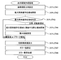
- the CPU 11 of the medical image display apparatus 1 performs an image projection direction setting process (step 41).
- the image projection direction setting process is the same as step 21 in FIG.
- the CPU 11 performs a maximum pixel value existence area search process (step 42).
- the maximum pixel value existence area search process is the same as step 22 in FIG.
- the CPU 11 performs a maximum pixel value existence area determination process (step 43).
- the CPU 11 determines whether the maximum pixel value existence region 50 identified in step 42 is the heart region 30, the blood vessel / coronary artery region 31, or the plaque region 32.
- the process proceeds to step 44, and in the case of the heart region 30 or plaque region 32 that is the other region (“ Heart region or plaque region "), go to step 46.
- the CPU 11 When the maximum pixel value existence region 50 is the blood vessel / coronary artery region 31 (the “blood vessel / coronary artery region” in step 43), the CPU 11 performs a region of interest search process adjacent to the maximum pixel value existence region (step 43). 44).
- the region-of-interest search process adjacent to the maximum pixel value existence region is the same as step 24 in FIG.
- the CPU 11 performs a weighting factor setting process (step 45).
- the weighting factor setting process is the same as step 25 in FIG.
- the CPU 11 performs a projection pixel value calculation process (step 46).
- the projection pixel value calculation process is the same as step 26 in FIG.
- the CPU 11 performs a color value setting process (step 47).
- the CPU 11 calculates the ratio of the tissue of interest (here, lipid) in the lesion candidate area (here, the plaque area 32). More specifically, the CPU 11 extracts a pixel indicating lipid by threshold processing using pixel value information such as a CT value, and calculates the ratio of the pixel indicating lipid in the plaque region 32. Then, the CPU 11 converts the lipid ratio into a color value using the color table.
- the CPU 11 associates the projection pixel value set in step 46 with the color value set in step 47 and stores it in the main memory 15 or the like (step 48).
- the display image based on the projection pixel value is displayed with the color value superimposed, and it is possible to visually recognize whether the plaque is rich in lipid or not by the difference in gradation of the color value. it can.
- the CPU 11 executes the processing from step 42 to step 48 on all the pixels on the projection plane 34, that is, all the projection lines 40, thereby creating a display image.
- the medical image display apparatus sets the first region of interest that is the observation region in the volume data and the second region of interest that is the region of the lesion candidate related to the observation region. If the region of interest setting unit and the pixel having the reference pixel value on the target projection line are the pixels of the first region of interest, the adjacent region that is the second region of interest adjacent to the first region of interest on the target projection line A display image creation unit that creates a display image in which the size of the second region of interest can be identified, and a display unit that displays the display image are provided.
- the display image creation unit determines a weighting factor according to the size of the adjacent second region of interest. A value obtained by weighting the pixel value based on the pixel group of the adjacent second region of interest and the reference pixel value on the target projection line by the weighting factor may be set as the projection pixel value for the target projection line. Further, the display image creation unit calculates a first index value indicating a ratio of pixels indicating the target tissue in the adjacent second region of interest, and a color different from the projection pixel value according to the first index value The color value of the attribute is determined, and the display unit displays the color value superimposed on the display image.
- information on the presence / absence of a lesion candidate, information on the position and composition, and information based on the shape of a luminal organ and its surrounding area are displayed on one display image.
- the information necessary for diagnosis can be sufficiently displayed, and it is possible to assist in making a diagnosis with no oversight in a short time.
- a position where a lesion candidate exists is reflected as a location where the pixel value decreases in a luminal organ.
- information based on the shape of the luminal organ and the surrounding area is reflected as a difference in the degree of decrease in the pixel value.
- information regarding the composition of the lesion candidate is reflected as a difference in color value gradation.
- the CPU 11 of the medical image display apparatus 1 uses the ratio of pixels corresponding to the tissue of interest (for example, lipid) in the region of the lesion candidate (plaque etc.) in the display image creation process in step 13.
- a color value (color value) is set based on the two indexes of the ratio of the diameter of the observed region at the target location and the diameter of the surrounding observed site (blood vessel, coronary artery, etc.). Then, in the image display process in step 14, the CPU 11 superimposes and displays the color value on the display image.
- the CPU 11 calculates an index value indicating the ratio of pixels indicating the target tissue among the adjacent lesion candidate regions on the target projection line, and is a region located on the target projection line and the reference pixel.
- the number of pixels in the region of the observation region including the pixel having the value and the number of pixels in the region of the observation region that is located on the projection line adjacent to the target projection line and is located around the pixel having the reference pixel value An index value indicating the ratio of the two is calculated, and a color value having a color attribute different from the projection pixel value is determined according to these two index values.
- the CPU 11 of the medical image display apparatus 1 performs an image projection direction setting process (step 51).
- the image projection direction setting process is the same as step 21 in FIG.
- the CPU 11 performs a maximum pixel value existence area search process (step 52).
- the maximum pixel value existence area search process is the same as step 22 in FIG.
- the CPU 11 performs maximum pixel value existence area determination processing (step 53).
- the CPU 11 determines whether the maximum pixel value existence region 50 identified in step 52 is the heart region 30, the blood vessel / coronary artery region 31, or the plaque region 32.
- the process proceeds to step 54, and in the case of the heart region 30 or the plaque region 32 that is the other region (“53” in step 53).
- Heart region or plaque region ") go to step 58.
- the CPU 11 When the maximum pixel value existence region 50 is the blood vessel / coronary artery region 31 in which the maximum pixel value existence region 50 is the observation region (“blood vessel / coronary artery region” in step 53), the CPU 11 performs a region of interest search process adjacent to the maximum pixel value existence region ( Step 54).
- the region-of-interest search process adjacent to the maximum pixel value existence region is the same as step 24 in FIG.
- the CPU 11 performs a weighting coefficient setting process (step 55).
- the weighting factor setting process is the same as step 25 in FIG.
- the CPU 11 performs observation site region distance calculation processing (step 56).
- the observation region distance calculation process is the same as step 35 in FIG.
- the CPU 11 performs observation site region distance ratio calculation processing (step 57). Based on the result of step 56, the CPU 11 determines the distance (the blood vessel / coronary artery blood vessel) of the observation site area at the position of interest with respect to the calculated distance (in this case, the blood vessel / coronary artery diameter). (Diameter) ratio is calculated. For example, when the blood vessel / coronary artery region 31 that is the maximum pixel value existence region 50 is a stenotic region, the ratio calculated in step 57 is a small value. On the other hand, when the blood vessel / coronary artery region 31 that is the maximum pixel value existence region 50 is a normal part, the ratio calculated in step 57 is a value close to 1.
- the CPU 11 performs attention tissue ratio calculation processing (step 58).
- the attention tissue ratio calculation process is the same as part of the process in step 47 of FIG. That is, the CPU 11 extracts a pixel indicating a tissue of interest (here, lipid) by threshold processing using pixel value information such as a CT value, for example, and focuses attention in a lesion candidate region (here, plaque region 32). Calculate the percentage of tissue (lipid).
- the CPU 11 performs a projection pixel value calculation process (step 59).
- the projection pixel value calculation process is the same as step 26 in FIG.
- the CPU 11 performs a color value setting process (step 60).
- the CPU 11 calculates the ratio of the distance of the observation region calculated in step 57 (here, the ratio of the blood vessel diameter of the blood vessel / coronary artery, that is, the blood vessel of the position of interest / the blood vessel of the coronary artery with respect to the blood vessel diameter of the peripheral position)
- the color value is set using a color map based on the ratio of the diameter) and the tissue ratio of interest (here, the lipid ratio) calculated in step 58.
- the color map will be described with reference to FIG.
- FIG. 12 shows a two-dimensional color map 80.
- the ratio of blood vessel diameters of blood vessels and coronary arteries is an axis 81
- the lipid ratio is an axis 82.
- the CPU 11 uniquely sets a color value from the two-dimensional color map 80 according to the ratio of the blood vessel diameter of the blood vessel / coronary artery and the lipid ratio. Note that FIG. 12 is converted to a gray scale image due to limitations of the patent drawing.
- the CPU 11 associates the color value set in step 60 with the projection pixel value set in step 59 and stores it in the main memory 15 or the like (step 61).
- the display image based on the projection pixel value is displayed with the color value superimposed, and the blood vessel diameter of the blood vessel / coronary artery at the position of interest is reduced due to the difference in gradation of the color value. And whether or not the plaques are rich in lipids.
- the CPU 11 executes the processing from step 52 to step 61 on all the pixels on the projection plane 34, that is, all the projection lines 40, thereby creating a display image.
- the medical image display apparatus sets the first region of interest that is the observation region in the volume data and the second region of interest that is the region of the lesion candidate related to the observation region. If the region of interest setting unit and the pixel having the reference pixel value on the target projection line are the pixels of the first region of interest, the adjacent region that is the second region of interest adjacent to the first region of interest on the target projection line A display image creation unit that creates a display image in which the size of the second region of interest can be identified, and a display unit that displays the display image are provided.
- the display image creation unit determines a weighting factor according to the size of the adjacent second region of interest.
- a value obtained by weighting the pixel value based on the pixel group of the adjacent second region of interest and the reference pixel value on the target projection line by the weighting factor may be set as the projection pixel value for the target projection line.
- the display image creation unit calculates a first index value indicating a ratio of pixels indicating the target tissue in the adjacent second region of interest, and is a region located on the target projection line, and The number of pixels of the first region of interest including a pixel having a reference pixel value, and the first region located on a projection line adjacent to the target projection line and located around a pixel having the reference pixel value Calculating a second index value indicating a ratio with the number of pixels of the region of interest, determining a color value of a color attribute different from the projection pixel value according to the first index value and the second index value, and the display unit Displays the color value superimposed on the display image.
- information on the presence / absence of a lesion candidate, information on the position and composition, and information based on the shape of the luminal organ and its surrounding area are displayed on one display image.
- the information necessary for diagnosis can be sufficiently displayed, and it is possible to assist in making a diagnosis with no oversight in a short time.
- the position where the lesion candidate exists is reflected as a location where the pixel value decreases in the luminal organ.
- information based on the shape of the luminal organ and the surrounding area is reflected as a difference in the degree of decrease in the pixel value.
- two types of information related to the composition of the lesion candidate are reflected as a difference in color value gradation.
Landscapes
- Health & Medical Sciences (AREA)
- Life Sciences & Earth Sciences (AREA)
- Engineering & Computer Science (AREA)
- Medical Informatics (AREA)
- Physics & Mathematics (AREA)
- General Health & Medical Sciences (AREA)
- Veterinary Medicine (AREA)
- Biomedical Technology (AREA)
- Molecular Biology (AREA)
- Surgery (AREA)
- Animal Behavior & Ethology (AREA)
- Pathology (AREA)
- Public Health (AREA)
- Biophysics (AREA)
- Heart & Thoracic Surgery (AREA)
- Nuclear Medicine, Radiotherapy & Molecular Imaging (AREA)
- Radiology & Medical Imaging (AREA)
- High Energy & Nuclear Physics (AREA)
- Optics & Photonics (AREA)
- Human Computer Interaction (AREA)
- Quality & Reliability (AREA)
- Computer Vision & Pattern Recognition (AREA)
- General Physics & Mathematics (AREA)
- Theoretical Computer Science (AREA)
- Apparatus For Radiation Diagnosis (AREA)
- Magnetic Resonance Imaging Apparatus (AREA)
- Image Processing (AREA)
- Ultra Sonic Daignosis Equipment (AREA)
Abstract
Description
また、特許文献2では、PCI(Percutaneous Coronary Intervention:経皮的冠動脈形成術)治療時のガイド画像として表示されるX線透視投影画像に対して、奥行きに関する情報を重畳して表示することが記載されている。
これに対して、特許文献1における血管の走行方向に沿った曲面によって切断された画像では、血管の走行方向に対して異常が存在する範囲を知ることができる。しかし、偏心性の異常の場合、切断曲面の方向によっては、画像上に異常箇所が表示されずに見落としが発生したり、あるいは曲面を変えながら観察する必要があり診断に膨大な時間を要する。
これに対して、特許文献2における技術では、血管病変部位が投影方向に対して3次元血管芯線よりも手前にあるのか、又は奥にあるのかを知ることができる。しかし、前述したように、血管の診断においては、プラーク等による血管径の変化の有無や度合い、血管径の変化が同心性であるか偏心性であるかの違いだけでなく、血管径の変化を伴わない代償性拡大やプラークの性状(脂質の割合)及びそれらの異常の存在箇所等、異常の存在有無・位置情報・組成情報を観察する必要がある。従って、特許文献2における奥行きに関する情報だけでは、血管の診断に必要な情報が十分に表示されているとは言えない。
最初に、図1、図2を参照しながら、全ての実施の形態に共通する医用画像表示装置1のハードウエア構成及び処理の概要を説明する。
マウス13は、操作者によるデータの入力を支援する。操作者がディスプレイ18に表示される画像やラジオスイッチ等のソフトウエアによって作られたスイッチ等にマウス13のカーソルを移動し、その移動先の位置をクリックすると、CPU11に所定の入力データが伝達される。
キーボード14は、磁気ディスク16から読み出したい医用画像を特定するためのID情報や、ディスプレイ18に表示される医用画像の診断レポート等、主に文字入力が適当な場合における入力装置である。
磁気ディスク16は、各種のコンピュータプログラムを記憶する。また、磁気ディスク16は、医用画像撮影装置20によって撮影された被検体の断層像を、LAN21及びデータ転送バス19を介して受信し、記憶する。磁気ディスク16は、コンピュータシステムにおける外部記憶装置の一例である。外部記憶装置としては、フレキシブルディスク、光(磁気)ディスク、ZIPメモリ、USBメモリ等、記憶媒体であればあらゆるものを含む。
ディスプレイ18は、表示メモリ17から信号転送された医用画像とそれに付帯する各種情報を表示する。
医用画像撮影装置20は、X線CT装置、MRI装置、超音波装置、シンチレーションカメラ装置、PET装置、SPECT装置等、被検体の断層像を得ることができるものである。
LAN21は、医用画像撮影装置20と医用画像表示装置1とを信号送受可能に接続するものである。尚、LAN21の代わりに、インターネット等公衆回線であってもよい。
CPU11は、例えば、CT値等の画素値情報を用いたしきい値処理によって領域の抽出を行う。例えば、造影剤を用いたCT撮影の場合、造影剤が注入された血管・冠動脈のCT値と、血管・冠動脈周辺に存在するプラークのCT値は、大きな違いがある。従って、CPU11は、血管・冠動脈領域と、血管・冠動脈領域周辺のプラーク領域を容易に区別することができる。尚、MRI装置の場合、撮影方法によって画素値が変わる為、撮影方法に合わせて、しきい値処理におけるしきい値を適宜変更する。
CPU11は、例えば、注目投影線上の基準画素値を有する画素が観察部位の領域の画素の場合には、この観察部位の領域に隣接する病変候補の領域の大きさが識別可能となる表示画像を作成する。基準画素値は、例えば、注目投影線上の最大画素値、注目投影線上の最小画素値、注目投影線上の予め定められた画素値に最も近い画素値等である。
尚、気管支の診断には、最小画素値投影法(MINIP:MINimum Intensity Projection)等が用いられることもある。そこで、観察対象が気管支の場合には、基準画素値を注目投影線上の最小画素値としても良い。
CPU11は、例えば、ある1つの投影方向から見た表示画像のみを表示するようにしても良い。又は、CPU11は、予め設定された複数の投影方向から見た表示画像を同時に表示するようにしても良い。又は、CPU11は、予め設定された複数の投影方向から見た表示画像を時間的に連続に表示するようにしても良い。
尚、本発明では、後述するように、1枚の表示画像だけであっても、診断に必要な情報を十分に表示することが可能である。
図3から図7を参照しながら、本発明を適用する第1の実施の形態について説明する。
第1の実施形態では、医用画像表示装置1のCPU11は、ステップ13の表示画像作成処理において、観察部位(血管・冠動脈等)の領域の距離(血管径)と隣接する病変候補(プラーク等)の領域の距離を用いて投影画素値を設定し、表示画像を作成する。
より詳しくは、CPU11は、注目投影線上の基準画素値を有する画素が観察部位の領域の画素の場合には、注目投影線上の隣接する病変候補の領域の大きさに応じて重み係数を決定し、注目投影線上の隣接する病変候補の領域の画素群に基づく画素値、及び、注目投影線上の基準画素値を重み係数によって重み付けした値を、注目投影線に対する投影画素値として設定する。
特に、CPU11は、注目投影線上の隣接する病変候補の領域の画素数、及び、注目投影線上の基準画素値を含む観察部位の領域の画素数に基づいて、重み係数を決定する。
操作者が、入力装置を介して画像を投影する方向を指示すると、CPU11は、指示に応じて、投影方向33及び投影面34を設定する。投影面34は、指示された投影方向33に垂直に、投影方向毎に設定される。例えば、操作者が、マウス13やキーボード14等を操作して、投影方向33を規定する投影角度を入力するようにしても良い。また、操作者によるマウス13を用いたドラッグ操作により、投影方向や投影面の向きを回転させながら指定するようにしてもよい。さらに、CPU11が、予め経験的に定められた投影角度を設定するようにしても良い。
投影方向33は、図4に示すように一方向だけ設定しても良いし、複数の方向を設定しても良い。
投影法は、透視投影でも良いし、平行投影でも良い。透視投影の場合、人間が見るものと同じ投影像を得ることができる。また、平行投影の場合、投影線同士が平行なので、CPU11が行う処理を簡略化することができる。
CPU11は、隣接関心領域51が手前側のみに存在する場合、奥側のみに存在する場合と同様に、隣接関心領域51を特定する。
また、CPU11は、隣接関心領域51が奥側及び手前側の両方に存在する場合、両方とも同じ関心領域(例えば、両方ともプラーク領域32)であれば、両方を合わせて、隣接関心領域51として特定する。
また、CPU11は、隣接関心領域51が奥側及び手前側の両方に存在する場合、互いに異なる関心領域(例えば、心臓領域30とプラーク領域32)であれば、プラーク領域32を優先して、隣接関心領域51として特定する。


図7(b)を参照すれば分かるように、このように、観察部位領域の画素であって、画素値が周辺の画素の画素値から著しく低下する箇所は、血管が狭窄するタイプの異常である可能性が高い箇所と言える。
図7(c)を参照すれば分かるように、このように、観察部位領域の画素であって、周辺の画素の画素値からの画素値の低下が中程度になる箇所は、血管径の変化がなく血管外側方向へプラークが拡大するタイプ(代償性拡大等と呼ばれる。)の異常である可能性が高い箇所と言える。
特に、第1の実施の形態では、病変候補が存在する位置が、管腔臓器の中で画素値が低下する箇所として画像に反映される。また、管腔臓器とその周辺の領域の形状に基づく情報が、画素値の低下度合の違いとして反映される。
例えば、前述の説明のように、式(3)におけるICが、ステップ22において特定された投影線40全体の中で最も大きい画素値の場合、式(3)におけるIPは、投影線40上の隣接関心領域51の最小画素値又は平均画素値が望ましい。すなわち、基準画素値が注目投影線上の最大画素値の場合には、CPU11は、注目投影線上の隣接関心領域の平均画素値又は最小画素値を式(3)におけるIPに代入して、投影画素値を設定することが望ましい。これによって、病変候補が存在する画素の画素値と、周辺の観察部位の領域(血管・冠動脈等)の画素の画素値との差が大きくなり、病変候補の位置がより視認し易くなる。
図8、図9を参照しながら、本発明を適用する第2の実施の形態について説明する。
第2の実施の形態では、医用画像表示装置1のCPU11は、ステップ13の表示画像作成処理において、観察部位(血管・冠動脈等)の領域の距離(血管径)と隣接する病変候補(プラーク等)の領域の距離や周辺の観察部位の領域の距離(血管径)の変化を用いて色値(カラー値)を設定する。そして、CPU11は、ステップ14における画像表示処理において、表示画像に色値を重畳して表示する。
より詳しくは、CPU11は、注目投影線上の基準画素値を注目投影線に対する投影画素値として設定し、注目投影線上の基準画素値を有する画素が観察部位(血管・冠動脈等)の領域の画素の場合には、注目投影線上の隣接する病変候補の領域(プラーク領域等)の大きさに応じて投影画素値と異なる色属性の色値を決定する。色属性としては、例えば、色相、彩度、明度、透明度等が考えられる。
特に、CPU11は、注目投影線上に位置する領域であり、かつ注目投影線上の基準画素値を有する画素を含む観察部位の領域の画素数、及び、注目投影線に隣接する投影線上に位置する領域であり、かつ基準画素値を有する画素の周辺に位置する観察部位の領域の画素数に基づいて、色値を決定する。
次に、CPU11は、最大画素値存在領域探索処理を行う(ステップ32)。最大画素値存在領域探索処理は、図3のステップ22と同様である。
最大画素値存在領域50の距離を算出する、注目する投影線40の周辺の投影線の範囲は、予め設定しておく。
そして、CPU11は、注目している位置の観察部位領域の距離(血管・冠動脈径)が、周辺の位置の観察部位領域の距離(血管・冠動脈径)と比べて縮んでいる場合は、カラーテーブルの緑から赤の領域を使用し、病変候補領域の画素数NP(プラーク領域の距離)が大きいほど赤に近い色を使用する。また、CPU11は、注目している位置の観察部位領域の距離(血管・冠動脈径)が、周辺の位置の観察部位領域の距離(血管・冠動脈径)と比べて縮んでいない場合は、カラーテーブルの緑から青の領域を使用し、病変候補領域の画素数NP(プラーク領域の距離)が大きいほど青に近い色を使用する。
次に、CPU11は、ステップ37において設定された投影画素値に、ステップ36において設定されたカラー値を対応付けて主メモリ15等に記憶する(ステップ38)。
第2の実施の形態では、投影画素値に基づく表示画像は、カラー値が重畳されて表示され、カラー値の階調の違いによって、注目している位置の血管・冠動脈の血管径が縮んでいるか否かを視認することができる。
図9(b)の例では、偏心性プラーク72が存在する位置に、赤に近いカラー値が重畳されることになる。これは、注目している位置の血管・冠動脈径(投影線71上の血管・冠動脈73の距離)が、周辺の位置の血管・冠動脈径(投影線71の周辺の投影線上の血管・冠動脈73の距離)と比べて縮んでいる為である。
図9(b)を参照すれば分かるように、このように赤に近いカラー値が重畳される箇所は、血管が狭窄するタイプの異常である可能性が高い箇所と言える。
図9(c)を参照すれば分かるように、このように青に近いカラー値が重畳される箇所は、血管径の変化がなく血管外側方向へプラークが拡大するタイプ(代償性拡大等と呼ばれる。)の異常である可能性が高い箇所と言える。
特に、第2の実施の形態では、病変候補が存在する位置にカラー値が重畳される。また、管腔臓器とその周辺の領域の形状に基づく情報が、カラー値の階調の違いとして反映される。
図10を参照しながら、本発明を適用する第3の実施の形態について説明する。
第3の実施の形態では、医用画像表示装置1のCPU11は、ステップ13の表示画像作成処理において、第1の実施の形態によって作成される表示画像に対して、病変候補(プラーク等)の領域内の、注目組織(例えば、脂質)相当の画素値の割合を色値(カラー値)に変換し、ステップ14における画像表示処理において、表示画像に色値を重畳して表示する。
より詳しくは、第3の実施の形態では、CPU11は、注目投影線上の隣接する病変候補の領域の中で注目組織を示す画素の割合を示す指標値を算出し、算出された指標値に応じて投影画素値と異なる色属性の色値を決定する。
次に、CPU11は、最大画素値存在領域探索処理を行う(ステップ42)。最大画素値存在領域探索処理は、図3のステップ22と同様である。
次に、CPU11は、投影画素値算出処理を行う(ステップ46)。投影画素値算出処理は、図3のステップ26と同様である。
第3の実施の形態では、投影画素値に基づく表示画像は、カラー値が重畳されて表示され、カラー値の階調の違いによって、プラークが脂質に富んだものか否かを視認することができる。
特に、第3の実施の形態では、病変候補が存在する位置が、管腔臓器の中で画素値が低下する箇所として反映される。また、管腔臓器とその周辺の領域の形状に基づく情報が、画素値の低下度合の違いとして反映される。また、病変候補の組成に関する情報が、カラー値の階調の違いとして反映される。
図11、図12を参照しながら、本発明を適用する第4の実施の形態について説明する。
第4の実施の形態では、医用画像表示装置1のCPU11は、ステップ13の表示画像作成処理において、病変候補(プラーク等)の領域内の、注目組織(例えば、脂質)相当の画素の割合、及び、注目箇所の観察部位の径と周辺の観察部位(血管・冠動脈等)の径との比、の2つの指標に基づいて色値(カラー値)を設定する。そして、CPU11は、ステップ14における画像表示処理において、表示画像に色値を重畳して表示する。
より詳しくは、CPU11は、注目投影線上の隣接する病変候補の領域の中で注目組織を示す画素の割合を示す指標値を算出し、更に、注目投影線上に位置する領域であり、かつ基準画素値を有する画素を含む観察部位の領域の画素数と、注目投影線に隣接する投影線上に位置する領域であり、かつ基準画素値を有する画素の周辺に位置する観察部位の領域の画素数との比を示す指標値を算出し、これら2つの指標値に応じて投影画素値と異なる色属性の色値を決定する。
次に、CPU11は、最大画素値存在領域探索処理を行う(ステップ52)。最大画素値存在領域探索処理は、図3のステップ22と同様である。
次に、CPU11は、観察部位領域距離算出処理を行う(ステップ56)。観察部位領域距離算出処理は、図8のステップ35と同様である。
次に、CPU11は、投影画素値算出処理を行う(ステップ59)。投影画素値算出処理は、図3のステップ26と同様である。
第4の実施の形態では、投影画素値に基づく表示画像は、カラー値が重畳されて表示され、カラー値の階調の違いによって、注目している位置の血管・冠動脈の血管径が縮んでいるか否か、及び、プラークが脂質に富んだものか否かを視認することができる。
特に、第4の実施の形態では、病変候補が存在する位置が、管腔臓器の中で画素値が低下する箇所として反映される。また、管腔臓器とその周辺の領域の形状に基づく情報が、画素値の低下度合の違いとして反映される。また、病変候補の組成に関する2種類の情報が、カラー値の階調の違いとして反映される。
Claims (9)
- ボリュームデータ中の観察部位領域である第1関心領域、及び、前記観察部位に係る病変候補の領域である第2関心領域を設定する関心領域設定部と、
注目投影線上の基準画素値を有する画素が前記第1関心領域の画素の場合には、前記注目投影線上の当該第1関心領域に隣接する前記第2関心領域である隣接第2関心領域の大きさが識別可能となる表示画像を作成する表示画像作成部と、
前記表示画像を表示する表示部と、を備える医用画像表示装置。 - 前記表示画像作成部は、前記注目投影線上の基準画素値を有する画素が前記第1関心領域の画素の場合には、前記隣接第2関心領域の大きさに応じて重み係数を決定し、前記隣接第2関心領域の画素群に基づく画素値及び前記注目投影線上の基準画素値を前記重み係数によって重み付けした値を、前記注目投影線に対する投影画素値として設定する請求項1に記載の医用画像表示装置。
- 前記表示画像作成部は、前記注目投影線上の基準画素値を前記注目投影線に対する投影画素値として設定し、前記注目投影線上の基準画素値を有する画素が前記第1関心領域の画素の場合には、前記隣接第2関心領域の大きさに応じて前記投影画素値と異なる色属性の色値を決定し、
前記表示部は、前記表示画像に前記色値を重畳して表示する請求項1に記載の医用画像表示装置。 - 前記表示画像作成部は、前記隣接第2関心領域の画素数、及び前記基準画素値を含む前記第1関心領域の画素数に基づいて、前記重み係数を決定する請求項2に記載の医用画像表示装置。
- 前記表示画像作成部は、前記注目投影線上に位置する領域であり、かつ前記基準画素値を有する画素を含む前記第1関心領域の画素数、及び、前記注目投影線に隣接する投影線上に位置する領域であり、かつ前記基準画素値を有する画素の周辺に位置する前記第1関心領域の画素数に基づいて、前記色値を決定する請求項3に記載の医用画像表示装置。
- 前記表示画像作成部は、前記隣接第2関心領域の中で注目組織を示す画素の割合を示す第1指標値を算出し、前記第1指標値に応じて前記投影画素値と異なる色属性の色値を決定し、
前記表示部は、前記表示画像に前記色値を重畳して表示する請求項2に記載の医用画像表示装置。 - 前記表示画像作成部は、前記隣接第2関心領域の中で注目組織を示す画素の割合を示す第1指標値を算出し、更に、前記注目投影線上に位置する領域であり、かつ前記基準画素値を有する画素を含む前記第1関心領域の画素数と、前記注目投影線に隣接する投影線上に位置する領域であり、かつ前記基準画素値を有する画素の周辺に位置する前記第1関心領域の画素数との比を示す第2指標値を算出し、前記第1指標値及び前記第2指標値に応じて前記投影画素値と異なる色属性の色値を決定し、
前記表示部は、前記表示画像に前記色値を重畳して表示する請求項2に記載の医用画像表示装置。 - 前記表示画像作成部は、前記基準画素値が前記注目投影線上の最大画素値の場合には、前記隣接第2関心領域の画素群に基づく画素値として、前記隣接第2関心領域の平均画素値又は前記隣接第2関心領域の最小画素値を設定し、前記基準画素値が前記注目投影線上の最小画素値の場合には、前記隣接第2関心領域の画素群に基づく画素値として、前記隣接第2関心領域の平均画素値又は前記隣接第2関心領域の最大画素値を設定する請求項2に記載の医用画像表示装置。
- ボリュームデータ中の観察部位の領域である第1関心領域、及び、前記観察部位に係る病変候補の領域である第2関心領域を設定する関心領域設定ステップと、
注目投影線上の基準画素値を有する画素が前記第1関心領域の画素の場合には、前記注目投影線上の当該第1関心領域に隣接する前記第2関心領域である隣接第2関心領域の大きさが識別可能となる表示画像を作成する表示画像作成ステップと、
前記表示画像を表示する表示ステップと、
を含む医用画像表示方法。
Priority Applications (3)
| Application Number | Priority Date | Filing Date | Title |
|---|---|---|---|
| US14/112,103 US9135702B2 (en) | 2011-04-20 | 2012-02-22 | Image display device for medical applications, image display method for medical applications |
| JP2013510911A JP5980776B2 (ja) | 2011-04-20 | 2012-02-22 | 医用画像表示装置、医用画像表示方法 |
| CN201280019337.6A CN103491877B (zh) | 2011-04-20 | 2012-02-22 | 医用图像显示装置、医用图像显示方法 |
Applications Claiming Priority (2)
| Application Number | Priority Date | Filing Date | Title |
|---|---|---|---|
| JP2011093569 | 2011-04-20 | ||
| JP2011-093569 | 2011-04-20 |
Publications (1)
| Publication Number | Publication Date |
|---|---|
| WO2012144266A1 true WO2012144266A1 (ja) | 2012-10-26 |
Family
ID=47041388
Family Applications (1)
| Application Number | Title | Priority Date | Filing Date |
|---|---|---|---|
| PCT/JP2012/054271 Ceased WO2012144266A1 (ja) | 2011-04-20 | 2012-02-22 | 医用画像表示装置、医用画像表示方法 |
Country Status (4)
| Country | Link |
|---|---|
| US (1) | US9135702B2 (ja) |
| JP (1) | JP5980776B2 (ja) |
| CN (1) | CN103491877B (ja) |
| WO (1) | WO2012144266A1 (ja) |
Cited By (3)
| Publication number | Priority date | Publication date | Assignee | Title |
|---|---|---|---|---|
| CN110753954A (zh) * | 2017-04-17 | 2020-02-04 | 雷神公司 | 用于组合彩色3d图像的系统和方法 |
| JP2021000473A (ja) * | 2012-11-30 | 2021-01-07 | キヤノンメディカルシステムズ株式会社 | カラーマップの生成方法、医用画像処理装置および医用画像処理システム |
| JP2023142112A (ja) * | 2022-03-24 | 2023-10-05 | 株式会社日立製作所 | 画像処理装置及び画像処理方法 |
Families Citing this family (8)
| Publication number | Priority date | Publication date | Assignee | Title |
|---|---|---|---|---|
| JP5950619B2 (ja) * | 2011-04-06 | 2016-07-13 | キヤノン株式会社 | 情報処理装置 |
| DE102015204957A1 (de) * | 2014-03-27 | 2015-10-01 | Siemens Aktiengesellschaft | Bildgebendes Tomosynthesesystem, insbesondere Mammographiesystem |
| JP2017161439A (ja) * | 2016-03-11 | 2017-09-14 | 日本メジフィジックス株式会社 | 画像処理システム |
| US10198626B2 (en) * | 2016-10-19 | 2019-02-05 | Snap Inc. | Neural networks for facial modeling |
| JP7192133B2 (ja) * | 2019-08-19 | 2022-12-19 | 富士フイルム株式会社 | 超音波診断装置、及び超音波診断装置の制御方法 |
| WO2022021224A1 (zh) * | 2020-07-30 | 2022-02-03 | 深圳迈瑞生物医疗电子股份有限公司 | 样本分类方法、装置和存储介质 |
| JP2023073628A (ja) * | 2021-11-16 | 2023-05-26 | キヤノンメディカルシステムズ株式会社 | X線診断装置およびx線条件設定方法 |
| CN114098807B (zh) * | 2021-11-26 | 2024-07-19 | 中国人民解放军海军军医大学 | 一种胸腹部超声扫查辅助装置、方法、介质及电子设备 |
Citations (5)
| Publication number | Priority date | Publication date | Assignee | Title |
|---|---|---|---|---|
| JP2006034983A (ja) * | 2004-07-29 | 2006-02-09 | Siemens Ag | 血管内の沈着の可視化方法および装置 |
| JP2006238938A (ja) * | 2005-02-28 | 2006-09-14 | Ziosoft Inc | 画像処理方法 |
| JP2009034494A (ja) * | 2007-07-10 | 2009-02-19 | Toshiba Corp | X線撮影装置、画像処理装置および画像処理プログラム |
| JP2010000306A (ja) * | 2008-06-23 | 2010-01-07 | Toshiba Corp | 医用画像診断装置、画像処理装置、及びプログラム |
| JP2010131315A (ja) * | 2008-12-08 | 2010-06-17 | Toshiba Corp | 医用画像処理装置及び医用画像処理プログラム |
Family Cites Families (3)
| Publication number | Priority date | Publication date | Assignee | Title |
|---|---|---|---|---|
| JP4200546B2 (ja) | 1998-03-09 | 2008-12-24 | 株式会社日立メディコ | 画像表示装置 |
| CN102172330B (zh) * | 2007-07-10 | 2013-03-27 | 株式会社东芝 | X射线摄影装置以及图像处理显示装置 |
| GB0910138D0 (en) * | 2009-06-12 | 2009-07-29 | Siemens Medical Solutions | Combination of MIP and anatomical information |
-
2012
- 2012-02-22 CN CN201280019337.6A patent/CN103491877B/zh not_active Expired - Fee Related
- 2012-02-22 WO PCT/JP2012/054271 patent/WO2012144266A1/ja not_active Ceased
- 2012-02-22 JP JP2013510911A patent/JP5980776B2/ja active Active
- 2012-02-22 US US14/112,103 patent/US9135702B2/en not_active Expired - Fee Related
Patent Citations (5)
| Publication number | Priority date | Publication date | Assignee | Title |
|---|---|---|---|---|
| JP2006034983A (ja) * | 2004-07-29 | 2006-02-09 | Siemens Ag | 血管内の沈着の可視化方法および装置 |
| JP2006238938A (ja) * | 2005-02-28 | 2006-09-14 | Ziosoft Inc | 画像処理方法 |
| JP2009034494A (ja) * | 2007-07-10 | 2009-02-19 | Toshiba Corp | X線撮影装置、画像処理装置および画像処理プログラム |
| JP2010000306A (ja) * | 2008-06-23 | 2010-01-07 | Toshiba Corp | 医用画像診断装置、画像処理装置、及びプログラム |
| JP2010131315A (ja) * | 2008-12-08 | 2010-06-17 | Toshiba Corp | 医用画像処理装置及び医用画像処理プログラム |
Cited By (7)
| Publication number | Priority date | Publication date | Assignee | Title |
|---|---|---|---|---|
| JP2021000473A (ja) * | 2012-11-30 | 2021-01-07 | キヤノンメディカルシステムズ株式会社 | カラーマップの生成方法、医用画像処理装置および医用画像処理システム |
| JP7080940B2 (ja) | 2012-11-30 | 2022-06-06 | キヤノンメディカルシステムズ株式会社 | カラーマップの生成方法、医用画像処理装置および医用画像処理システム |
| CN110753954A (zh) * | 2017-04-17 | 2020-02-04 | 雷神公司 | 用于组合彩色3d图像的系统和方法 |
| JP2020516413A (ja) * | 2017-04-17 | 2020-06-11 | レイセオン カンパニー | 3d画像をカラーで結合するシステム及び方法 |
| CN110753954B (zh) * | 2017-04-17 | 2023-08-08 | 雷神公司 | 用于组合彩色3d图像的系统和方法 |
| JP2023142112A (ja) * | 2022-03-24 | 2023-10-05 | 株式会社日立製作所 | 画像処理装置及び画像処理方法 |
| JP7642585B2 (ja) | 2022-03-24 | 2025-03-10 | 株式会社日立製作所 | 画像処理装置及び画像処理方法 |
Also Published As
| Publication number | Publication date |
|---|---|
| US9135702B2 (en) | 2015-09-15 |
| US20140037167A1 (en) | 2014-02-06 |
| CN103491877B (zh) | 2015-11-25 |
| CN103491877A (zh) | 2014-01-01 |
| JPWO2012144266A1 (ja) | 2014-07-28 |
| JP5980776B2 (ja) | 2016-08-31 |
Similar Documents
| Publication | Publication Date | Title |
|---|---|---|
| JP5980776B2 (ja) | 医用画像表示装置、医用画像表示方法 | |
| CN102812380B (zh) | 医用图像处理装置 | |
| US8965074B2 (en) | Image processing apparatus | |
| US8611988B2 (en) | Projection image generation apparatus and method, and computer readable recording medium on which is recorded program for the same | |
| US9036882B2 (en) | Diagnosis assisting apparatus, diagnosis assisting method, and recording medium having a diagnosis assisting program stored therein | |
| JP5495357B2 (ja) | 画像表示方法及び医用画像診断システム | |
| US9582936B2 (en) | Method and apparatus for combining plurality of 2D images with 3D model | |
| JPWO2009116465A1 (ja) | 医用画像表示装置及び医用画像表示方法 | |
| JP5492024B2 (ja) | 領域分割結果修正装置、方法、及びプログラム | |
| JPWO2010055817A1 (ja) | 画像処理装置及び画像処理方法 | |
| EP2168492B1 (en) | Medical image displaying apparatus, medical image displaying method, and medical image displaying program | |
| JP4282939B2 (ja) | 超音波診断装置、画像処理装置、及び画像処理プログラム | |
| CN102138808A (zh) | 超声波诊断装置及医用图像处理装置 | |
| JP5194138B2 (ja) | 画像診断支援装置およびその動作方法、並びに画像診断支援プログラム | |
| JP6738631B2 (ja) | 医用画像処理装置、医用画像処理方法、及び医用画像処理プログラム | |
| US9585569B2 (en) | Virtual endoscopic projection image generating device, method and program | |
| JP2016202319A (ja) | 医用画像処理装置、医用画像処理方法、及び医用画像処理プログラム | |
| CN108269292B (zh) | 用于根据三维图像数据组产生二维投影图像的方法和设备 | |
| EP2272427B1 (en) | Image processing device and method, and program | |
| JP5498185B2 (ja) | 超音波診断装置及び超音波画像表示プログラム | |
| EP3423968B1 (en) | Medical image navigation system | |
| KR101117913B1 (ko) | 볼륨 데이터를 렌더링하는 초음파 시스템 및 방법 | |
| JP6647796B2 (ja) | 画像処理装置及びx線診断装置 | |
| JP2008180555A (ja) | 画像処理装置、画像処理方法、およびプログラム | |
| WO2010001327A1 (en) | Processing anatomy and associated quantitative analysis data of tissue |
Legal Events
| Date | Code | Title | Description |
|---|---|---|---|
| 121 | Ep: the epo has been informed by wipo that ep was designated in this application |
Ref document number: 12774576 Country of ref document: EP Kind code of ref document: A1 |
|
| ENP | Entry into the national phase |
Ref document number: 2013510911 Country of ref document: JP Kind code of ref document: A |
|
| WWE | Wipo information: entry into national phase |
Ref document number: 14112103 Country of ref document: US |
|
| NENP | Non-entry into the national phase |
Ref country code: DE |
|
| 122 | Ep: pct application non-entry in european phase |
Ref document number: 12774576 Country of ref document: EP Kind code of ref document: A1 |