WO2012144285A1 - Procédé de formation de film, support de mémoire informatique, et dispositif de formation de film - Google Patents
Procédé de formation de film, support de mémoire informatique, et dispositif de formation de film Download PDFInfo
- Publication number
- WO2012144285A1 WO2012144285A1 PCT/JP2012/057147 JP2012057147W WO2012144285A1 WO 2012144285 A1 WO2012144285 A1 WO 2012144285A1 JP 2012057147 W JP2012057147 W JP 2012057147W WO 2012144285 A1 WO2012144285 A1 WO 2012144285A1
- Authority
- WO
- WIPO (PCT)
- Prior art keywords
- template
- silane coupling
- coupling agent
- substrate
- release agent
- Prior art date
- Legal status (The legal status is an assumption and is not a legal conclusion. Google has not performed a legal analysis and makes no representation as to the accuracy of the status listed.)
- Ceased
Links
Images











Classifications
-
- G—PHYSICS
- G03—PHOTOGRAPHY; CINEMATOGRAPHY; ANALOGOUS TECHNIQUES USING WAVES OTHER THAN OPTICAL WAVES; ELECTROGRAPHY; HOLOGRAPHY
- G03F—PHOTOMECHANICAL PRODUCTION OF TEXTURED OR PATTERNED SURFACES, e.g. FOR PRINTING, FOR PROCESSING OF SEMICONDUCTOR DEVICES; MATERIALS THEREFOR; ORIGINALS THEREFOR; APPARATUS SPECIALLY ADAPTED THEREFOR
- G03F7/00—Photomechanical, e.g. photolithographic, production of textured or patterned surfaces, e.g. printing surfaces; Materials therefor, e.g. comprising photoresists; Apparatus specially adapted therefor
- G03F7/0002—Lithographic processes using patterning methods other than those involving the exposure to radiation, e.g. by stamping
-
- B—PERFORMING OPERATIONS; TRANSPORTING
- B82—NANOTECHNOLOGY
- B82Y—SPECIFIC USES OR APPLICATIONS OF NANOSTRUCTURES; MEASUREMENT OR ANALYSIS OF NANOSTRUCTURES; MANUFACTURE OR TREATMENT OF NANOSTRUCTURES
- B82Y10/00—Nanotechnology for information processing, storage or transmission, e.g. quantum computing or single electron logic
-
- B—PERFORMING OPERATIONS; TRANSPORTING
- B82—NANOTECHNOLOGY
- B82Y—SPECIFIC USES OR APPLICATIONS OF NANOSTRUCTURES; MEASUREMENT OR ANALYSIS OF NANOSTRUCTURES; MANUFACTURE OR TREATMENT OF NANOSTRUCTURES
- B82Y40/00—Manufacture or treatment of nanostructures
Definitions
- the present invention relates to a film forming method, a computer storage medium, and a film forming apparatus for forming a silane coupling agent on a substrate.
- a semiconductor wafer (hereinafter referred to as “wafer”) is subjected to a photolithography process to form a predetermined resist pattern on the wafer.
- the resist pattern When forming the above-described resist pattern, the resist pattern is required to be miniaturized in order to further increase the integration of the semiconductor device.
- the limit of miniaturization in the photolithography process is about the wavelength of light used for the exposure process. For this reason, it has been advancing to shorten the wavelength of exposure light.
- there are technical and cost limitations to shortening the wavelength of the exposure light source and it is difficult to form a fine resist pattern on the order of several nanometers, for example, only by the method of advancing the wavelength of light. is there.
- a mold release agent having liquid repellency with respect to the resist is usually formed on the surface of the template used in the above-described imprinting method so that the template can be easily peeled off from the resist.
- the release agent When forming the release agent on the template surface, first, the template surface is washed, and then the release agent is applied to the template surface. Next, the release agent is adhered to the surface of the template so that the release agent to be formed has a predetermined contact angle and can exhibit a liquid repellency function with respect to the resist. Specifically, by chemically reacting the mold release agent and the template surface, among the components contained in the mold release agent, a component having liquid repellency to the resist, such as a fluoride component, is adsorbed on the template surface. Let Thereafter, the unreacted portion of the release agent is removed, and a release agent having a predetermined film thickness is formed on the surface of the template.
- the unreacted part of the release agent means a part other than the part where the release agent is chemically reacted with the surface of the template.
- the present invention has been made in view of this point, and an object of the present invention is to appropriately form a silane coupling agent on a substrate and improve the throughput of the substrate processing.
- the present invention provides a film forming method for forming a silane coupling agent on a substrate, the supply step of supplying the silane coupling agent on the substrate, and the step of supplying the silane coupling agent on the substrate. Forming a film of the silane coupling agent on the substrate by applying ultrasonic vibration to the silane coupling agent supplied to the substrate.
- the surface of the substrate and the silane coupling agent are firmly bonded, and the adhesion between the surface of the substrate and the silane coupling agent is improved. Therefore, when ultrasonic vibration is applied to the silane coupling agent, the silane coupling agent can be brought into close contact with the surface of the substrate in a short time, and the silane coupling agent can be appropriately formed on the substrate. Thus, since the silane coupling agent can be brought into close contact with the surface of the substrate in a short time, the throughput of the entire substrate processing can also be improved.
- Another aspect of the present invention is a readable computer storage medium storing a program that operates on a computer of a control unit that controls the film forming apparatus in order to cause the film forming apparatus to execute the film forming method.
- the present invention provides a film forming apparatus for forming a silane coupling agent on a substrate, the silane coupling agent supplying unit supplying the silane coupling agent on the substrate, and the silane coupling agent An ultrasonic transducer that applies ultrasonic vibration to the silane coupling agent supplied from the supply unit onto the substrate.
- a silane coupling agent can be appropriately formed on a substrate, and the throughput of substrate processing can be improved.
- FIG. 1 is a plan view showing an outline of a configuration of a template processing apparatus 1 including a coating unit as a film forming apparatus according to the present embodiment.
- 2 and 3 are side views showing an outline of the configuration of the template processing apparatus 1.
- a template T as a substrate having a rectangular parallelepiped shape and having a predetermined transfer pattern C formed on the surface is used as shown in FIG.
- the transfer pattern C means the side of the template T which is formed with the surface T 1, the surface T 1 opposite to the surface of the backside T 2.
- a transparent material capable of transmitting light such as visible light, near ultraviolet light, and ultraviolet light, such as quartz glass, is used.
- Template processing unit 1 includes a plurality as shown in FIG. 1, for example, five of the template T or transferring, between the outside and the template processing apparatus 1 with the cassette unit, carrying out a template T the template cassette C T
- the template loading / unloading station 2 and the template processing station 3 including a plurality of processing units for performing predetermined processing on the template T are integrally connected.
- the template loading / unloading station 2 is provided with a cassette mounting table 10.
- the cassette mounting table 10 can mount a plurality of template cassettes CT in a line in the X direction (vertical direction in FIG. 1). That is, the template carry-in / out station 2 is configured to be capable of holding a plurality of templates T.
- the template carry-in / out station 2 is provided with a template carrier 12 that can move on a conveyance path 11 extending in the X direction.
- the template transport body 12 can be expanded and contracted in the horizontal direction, and can also move in the vertical direction and the vertical direction ( ⁇ direction), and can transport the template T between the template cassette CT and the template processing station 3.
- the template processing station 3 is provided with a transport unit 20 at the center thereof.
- a transport unit 20 for example, four processing blocks G1 to G4 in which various processing units are arranged in multiple stages are arranged.
- a first processing block G1 and a second processing block G2 are sequentially arranged from the template loading / unloading station 2 side on the front side of the template processing station 3 (X direction negative direction side in FIG. 1).
- a third processing block G3 and a fourth processing block G4 are arranged in this order from the template loading / unloading station 2 side on the back side of the template processing station 3 (X direction positive direction side in FIG. 1).
- a transition unit 21 for transferring the template T is disposed on the template loading / unloading station 2 side of the template processing station 3.
- the transport unit 20 has a transport arm that holds and transports the template T and is movable in the horizontal direction, the vertical direction, and the vertical direction.
- the transport unit 20 can transport the template T to various processing units (to be described later) arranged in the processing blocks G1 to G4 and the transition unit 21.
- the first processing block G1 applying a plurality of liquid processing units, for example, a liquid release agent and reaction accelerator of the surface T 1 of the template T as a silane coupling agent as shown in FIG. 2, formed A coating unit 30 as a film device and a rinsing unit 31 for rinsing the release agent on the template T are stacked in two stages in order from the bottom.
- the coating unit 32 and the rinsing unit 33 are stacked in two stages in order from the bottom.
- chemical chambers 34 and 35 for supplying various processing liquids to the liquid processing unit are provided at the lowermost stages of the first processing block G1 and the second processing block G2, respectively.
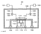
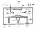
- the coating unit 30 has a processing container 100 in which a loading / unloading port (not shown) for the template T is formed on the side surface.
- a mounting table 101 on which the template T is mounted is provided on the bottom surface in the processing container 100.
- Template T has a surface T 1 is placed on the top surface of the mounting table 101 to face upward.
- a template moving mechanism 102 is provided as a substrate moving mechanism incorporating a drive unit. The template moving mechanism 102 allows the mounting table 101 and the template T mounted on the mounting table 101 to move in the horizontal direction.
- a top surface of the mounting table 101, the below the template T is mounted on the mounting table 101, a direction perpendicular to the surface T 1 of the template T, i.e. ultrasonic transducer for applying ultrasonic vibration in the vertical direction
- An ultrasonic transducer 110 is provided.
- the ultrasonic transducer 110 is provided with an ultrasonic oscillation device (not shown) for oscillating ultrasonic waves from the ultrasonic transducer 110.
- a transducer moving mechanism 111 with a built-in driving unit is provided below the ultrasonic transducer 110.
- the ultrasonic transducer 110 is movable in the horizontal direction by the transducer moving mechanism 111.
- the ultrasonic transducer 110 is movable independently of the mounting table 101.
- raising / lowering pins 112 for supporting the template T from below and raising / lowering it are provided inside the mounting table 101.
- the elevating pin 112 can be moved up and down by the elevating drive unit 113.
- the ultrasonic vibrator 110 is formed with a through-hole 114 that penetrates the ultrasonic vibrator 110 in the thickness direction, and the elevating pin 112 is inserted through the through-hole 114.
- a rail 120 extending along the Y direction is provided on the side of the mounting table 101 in the negative X direction (downward in FIG. 6).
- the rail 120 is formed, for example, from the outside of the mounting table 101 on the Y direction negative direction (left direction in FIG. 6) side to the Y direction positive direction (right direction in FIG. 6) side.
- a first arm 121 and a second arm 122 are attached to the rail 120.
- the first arm 121 supports a release agent nozzle 123 as a silane coupling agent supply unit that supplies a release agent onto the template T.
- the release agent nozzle 123 has, for example, an elongated shape along the X direction that is equal to or longer than the length of one side of the template T.
- the discharge port of the release agent nozzle 123 is formed in a slit shape.
- a supply pipe 125 that communicates with a release agent supply source 124 is connected to the release agent nozzle 123.
- a material having a liquid repellency with respect to a resist film on the wafer which will be described later, such as a fluorine-carbon compound, is used as the material of the release agent.
- the first arm 121 is movable on the rail 120 by the nozzle driving unit 126.
- the release agent nozzle 123 can move from the standby unit 127 installed on the outside in the Y direction positive direction side of the mounting table 101 to above the template T on the mounting table 101, and the surface T of the template T. 1 can be moved in the side direction of the template T.
- the first arm 121 can be moved up and down by a nozzle driving unit 126 and the height of the release agent nozzle 123 can be adjusted.
- the second arm 122 is supported by an alcohol nozzle 130 as a reaction accelerator supply unit that supplies alcohol as a reaction accelerator, for example, t-pentyl alcohol, onto the template T (on the mold release agent on the template T).
- the alcohol nozzle 130 has, for example, an elongated shape along the X direction that is equal to or longer than the length of one side of the template T.
- the discharge port of the alcohol nozzle 130 is formed in a slit shape.
- the alcohol nozzle 130 is connected to a supply pipe 132 communicating with an alcohol supply source 131 as shown in FIG.
- the alcohol that is a reaction accelerator can promote the chemical reaction between the surface T 1 of the template T and the release agent S.
- the second arm 122 is movable on the rail 120 by the nozzle driving unit 133.
- the alcohol nozzle 130 can move from the standby unit 134 installed on the outside in the Y direction positive direction side of the mounting table 101 to above the template T on the mounting table 101, and further on the surface T 1 of the template T. Can be moved in the side direction of the template T.
- the second arm 122 can be moved up and down by the nozzle driving unit 133, thereby adjusting the height of the alcohol nozzle 130.
- the configuration of the coating unit 32 is the same as the configuration of the coating unit 30 described above, and a description thereof will be omitted.
- the rinsing unit 31 has a processing container 140 in which a loading / unloading port (not shown) for the template T is formed on the side surface as shown in FIG.
- a dipping tank 141 for dipping the template T is provided on the bottom surface in the processing container 140.
- a rinse liquid for rinsing the release agent on the template T for example, an organic solvent is stored.
- a holding part 142 for holding the template T is provided on the ceiling surface in the processing container 140 and above the immersion tank 141.
- Holding portion 142, the outer peripheral portion of the rear surface T 2 of the template T has a chuck 143 for holding suction.
- Template T has a surface T 1 is held on the chuck 143 to face upward.
- the chuck 143 can be moved up and down by a lifting mechanism 144.
- the template T is immersed in the organic solvent stored in the immersion tank 141 in the state hold
- the holding unit 142 includes a gas supply unit 145 provided above the template T held by the chuck 143.
- the gas supply unit 145 can spray an inert gas such as nitrogen or a gas gas such as dry air downward, that is, on the surface T 1 of the template T held by the chuck 143.
- the rinse unit 31 is connected to an exhaust pipe (not shown) for exhausting the internal atmosphere.
- the cleaning unit 40 includes a processing container 150 in which a loading / unloading port (not shown) for the template T is formed on the side surface.
- a chuck 151 for attracting and holding the template T is provided in the processing container 150.
- a chuck drive unit 152 is provided below the chuck 151.
- the chuck driving unit 152 is provided on the bottom surface in the processing container 150 and is mounted on a rail 153 extending along the Y direction. The chuck 151 can be moved along the rail 153 by the chuck driving unit 152.
- An ultraviolet irradiation unit 154 that irradiates the template T held by the chuck 151 with ultraviolet rays is provided on the ceiling surface in the processing container 150 and above the rail 153.
- the ultraviolet irradiation unit 154 extends in the X direction as shown in FIG. Then, while moving the template T along the rail 153, by irradiating ultraviolet light onto the surface T 1 of the said template T from the ultraviolet irradiation unit 154, ultraviolet rays are irradiated on the entire surface of the surface T 1 of the template T.
- the configuration of the cleaning units 41 to 43 is the same as the configuration of the cleaning unit 40 described above, and a description thereof will be omitted.
- the control unit 160 is a computer, for example, and has a program storage unit (not shown).
- the program storage unit controls the transfer of the template T between the template loading / unloading station 2 and the template processing station 3, the operation of the drive system in the template processing station 3, and the like.
- the program that executes is stored.
- This program is recorded in a computer-readable storage medium such as a computer-readable hard disk (HD), flexible disk (FD), compact disk (CD), magnetic optical desk (MO), memory card, or the like. Or installed in the control unit 160 from the storage medium.
- HD computer-readable hard disk
- FD flexible disk
- CD compact disk
- MO magnetic optical desk
- the template processing apparatus 1 is configured as described above. Next, template processing performed in the template processing apparatus 1 will be described.
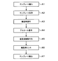
- FIG. 10 shows the main processing flow of this template processing
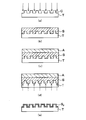
- FIG. 11 shows the state of the template T in each step.
- the template carrier 12, the template T is taken from the template cassette C T on the cassette mounting table 10, (step A1 of FIG. 10) that is being conveyed to the transition unit 21 of the template processing station 3.
- the template cassette C T the template T, the surface T 1 of the transfer pattern C is formed is accommodated so as to face upward, the template T in this state is conveyed to the transition unit 21.
- the transport unit 20 transports the template T to the cleaning unit 40 and sucks and holds it on the chuck 151.
- the template T is irradiated with ultraviolet rays from the ultraviolet irradiation unit 154 while moving the template T along the rails 153 by the chuck driving unit 152.
- the entire surface T 1 of the template T is irradiated with ultraviolet rays, organic contaminants, particles, and other impurities on the surface T 1 of the template T are removed, and the surface T 1 is cleaned. (Step A2 in FIG. 10).
- the template T is transported to the coating unit 30 by the transport unit 20.
- the template T conveyed to the coating unit 30 is transferred to the elevating pins 112 and placed on the placing table 101.
- the release agent S is supplied onto the template T from the release agent nozzle 123 while moving the release agent nozzle 123 in the side direction of the template T.
- the release agent S is applied to the surface T 1 the entire surface of the template T as shown in FIG. 11 (b) (step A3 in FIG. 10).
- ultrasonic vibration is applied from the ultrasonic vibrator 110 to the release agent S on the template T (step A5 in FIG. 10). Then, the chemical reaction between the surface T 1 and the release agent S of the template T is accelerated, adhesion to the surface T 1 and the release agent S of the template T is improved.
- the template T or the ultrasonic vibrator 110 is relatively moved by at least the template moving mechanism 102 or the vibrator moving mechanism 111. May be moved. In such a case, the vibration intensity of the ultrasonic vibration can be uniform within the template surface, the chemical reaction between the surface T 1 and the release agent S of the template T can be uniformly accelerated.
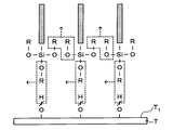
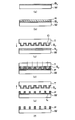
- FIG. 12 (a) is shown the state of the surface T 1 of the previous template T for imparting ultrasonic vibrations
- FIG. 12 (b) ⁇ (d) is a surface T 1 of the template T in applying ultrasonic vibration state Is shown.
- a hydroxyl group (OH group) is formed on the surface T 1 of the template T.
- the release agent molecule of the release agent S that is a silane coupling agent has two functional groups. That is, the OR group that is one functional group is bonded to the surface T 1 of the template T. Further, OR groups of adjacent release agent molecules are also bonded to each other. R is an alkyl group, for example, CH 3 .
- S G is a functional group that exhibits the release function, a fluoride component.
- ultrasonic vibration is applied from the ultrasonic vibrator 110 to the release agent S on the template T.
- the ultrasonic vibration is a compressional wave, the direction perpendicular to the surface T 1 of the template T, i.e. traveling in the thickness direction of the release agent S.
- the functional group S G of release agent S as shown in FIG. 12 (b) ⁇ (d) vibrates in the vertical direction.
- FIG. 12C when the functional group S G is elongated, the atoms of the functional group S G become sparse, and the alcohol A permeates the functional group S G.
- the inert gas or dry air for example nitrogen or the like to the release agent S on the template T, etc.
- the release agent S may be dried by spraying the gas gas.
- the template T is transported to the rinse unit 31 by the transport unit 20 and held by the holding unit 142. Subsequently, the holding unit 142 is lowered, and the template T is immersed in the organic solvent stored in the immersion tank 141.
- a predetermined time elapses, only the unreacted part of the release agent S, that is, only the part other than the part where the release agent S chemically reacts with the surface T 1 of the template T and adheres to the surface T 1 is peeled off.
- the release agent S on the surface T 1 of the template T in the above-described step A5 are in close contact, the release agent S distance from the surface T 1 of the predetermined template T it will not be peeled off.
- release film S F along the transfer pattern C on the template T is deposited in a predetermined thickness as shown in FIG. 11 (e) (step A6 in FIG. 10). Then, raise the holding portion 142 blows air gas to the template T from the gas supply unit 145, drying the surface T 1.
- the transport unit 20 the template T is carried to the transition unit 21 and returned to the template cassette C T by the template carrier 12 (step A7 in FIG. 10).
- the template processing apparatus 1 a series of template processing in template processing apparatus 1 is completed, the surface T 1 of the template T, the release agent S along the shape of the transfer pattern C is formed in a predetermined thickness.
- step A5 since the ultrasonic vibration to the release agent S on the template T from the ultrasonic transducer 110 is applied, the functional group S G of the release agent S is vibrated, Alcohol A enters between the release agent S and the surface T 1 of the template T. Then, hydrolysis of the release agent molecules by an alcohol A is promoted, the hydroxyl group of the surface T 1 of the hydrolyzed releasing agent molecule and the template T are coupled by dehydration condensation. Therefore, the chemical reaction between the surface T 1 of the template T and the release agent S is promoted, and the adhesion between the surface T 1 of the template T and the release agent S is improved. In other words, it can be brought into close contact with the surface T 1 of the template T of the release agent S in a short time. As a result, the throughput of the template processing in the steps A1 to A7 can be improved.
- the template T is made of quartz glass and is in an amorphous state. Therefore, the hydroxyl groups of the surface T 1 of the template T is disposed in irregular positions, also faces a random directions, it is difficult to react with the release agent S. According to the present embodiment, since the release agent S vibrates by applying ultrasonic vibration to the release agent S on the template T, the bond is promoted even for the bond that has been difficult to bond conventionally. Accordingly, with the surface T 1 and the release agent S of the template T capable of binding in a shorter time, it can be further strengthened the bond.
- ultrasonic vibration from the ultrasonic transducer 110 to the template T Since the vibration in the thickness direction (vertical direction) of the release agent S, also vibrates in the thickness direction function S G of the release agent S. That is, the moving direction of the vibration direction and alcohol A functional group S G match. Therefore, the movement of the alcohol A can be performed efficiently. Even by applying ultrasonic vibration from a direction other than the thickness direction of the release agent S, it is possible to vibrate the mold release agent S, the chemical surface T 1 and the release agent S of the template T than conventional The reaction can be promoted. Among these, this embodiment can promote the chemical reaction by moving the alcohol A most efficiently.
- alcohol A is used for hydrolysis of the release agent molecules, but water molecules contained in the atmosphere in the coating unit 30 may be used.
- the chemical reaction between the surface T 1 of the template T and the release agent S takes longer than using the alcohol A, but a mechanism for supplying the alcohol A (the alcohol nozzle 130 or the like) may be omitted. It is possible to simplify the apparatus configuration.
- the ultrasonic vibration is applied from the lower side of the template T in the coating unit 30, but may be applied from the upper side of the template T.
- the ultrasonic transducer 110 is provided on the ceiling surface of the processing container 100 at a position facing the template T mounted on the mounting table 101.
- a transducer moving mechanism 111 that moves the ultrasonic transducer 110 in the horizontal direction is also provided on the ceiling surface of the processing container 100.
- the direction perpendicular to the surface T 1 of the ultrasonic vibration template T that is, can be applied in the thickness direction of the release agent S, the release agent S is vibrated, the surface T 1 and the release of the template T The chemical reaction of the mold S can be promoted.
- the alcohol A is supplied onto the mold release agent S of the template T in the coating unit 30, but a mixed liquid of, for example, an organic solvent is supplied as the solvent of the alcohol A and the mold release agent S. May be.
- a mixed solution nozzle 200 is supported on the second arm 122 instead of the alcohol nozzle 130.
- a supply pipe 202 communicating with the organic solvent supply source 201 is connected to the mixed solution nozzle 200.
- step A ⁇ b> 4 the alcohol A supplied from the alcohol supply source 131 and the organic solvent supplied from the organic solvent supply source 201 are mixed in the mixed solution nozzle 200. Then, the liquid mixture is supplied onto the mold release agent S of the template T from the liquid mixture nozzle 200. Since the liquid mixture supplied onto the release agent S contains an organic solvent, the liquid mixture easily diffuses on the release agent S. If it does so, alcohol A can be more uniformly apply
- step A4 of the above embodiment alcohol A was applied on mold release agent S before mold release agent S on template T was dried, but mold release was performed before alcohol A was applied.
- the agent S may be dried. In such a case, it becomes difficult for the alcohol A to diffuse on the release agent S.
- the present embodiment can be applied even if the release agent S is dry.
- the alcohol A and the organic solvent are mixed in the mixed solution nozzle 200, but the mixing method of the alcohol A and the organic solvent is not limited to this.
- the mixed solution may be supplied to the mixed solution nozzle 200 from a mixed solution supply source (not shown) that mixes and stores the alcohol A and the organic solvent.
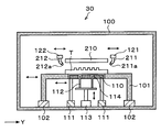
- a support plate 210 for diffusing the release agent S and alcohol A on the template T may be disposed above the mounting table 101 as shown in FIG.
- the support plate 210 has, for example, a flat plate shape.
- Support plate 210 is opposed to the template T on the table 101, the distance between the surface T 1 of the said template T is located at a predetermined distance, for example within 1mm position.
- the support plate 210 is disposed so as to cover the surface T 1 the entire surface of the template T.
- the support plate 210 can be moved in the processing container 100 by a moving mechanism (not shown).
- the first arm 121 supports a release agent nozzle 211 that is arranged so that the supply port 211a at the lower end thereof faces obliquely downward instead of the release agent nozzle 123.
- the supply port 211a of the release agent nozzle 211 may be, for example, a circular shape or a slit shape.
- the second arm 122 instead of the alcohol nozzle 130, also supports an alcohol nozzle 212 arranged so that the supply port 212 a at the lower end portion faces obliquely downward.
- the supply port 212a of the alcohol nozzle 212 may have a circular shape or a slit shape, for example.
- step A ⁇ b> 3 the release agent S is supplied from the release agent nozzle 211 between the end of the surface T ⁇ b> 1 of the template T and the end of the support plate 210. Supplied release agent S is diffused between the surface T 1 and the support plate 210 of the template T by capillarity (surface tension). Thereafter, in step A4, the alcohol A is provided between the end of the support plate 210 and the end portion of the surface T 1 of the template T from the alcohol nozzle 212. The supplied alcohol A diffuses between the release agent S of the template T and the support plate 210 by capillary action (surface tension).
- the release agent S and the alcohol A can easily diffuse on the template T, so that the release agent S and the alcohol A can be more uniformly applied on the template T.
- the chemical reaction between the surface T 1 and the release agent S can be promoted.
- the present embodiment can be applied even if the release agent S is dry.
- the support plate 210 has a flat plate shape, but may have a mesh shape. Even in such a case, the surface T 1 of the template T can be diffused by the surface tension of the release agent S and the alcohol A. In such a case, the release agent S and the alcohol A can also be supplied from above the support plate 210.
- Step A3 and Step A4 of the above embodiment for diffusing the release agent S and alcohols A in the surface T 1 of the template T, it may be moved template T.
- step A3 movement after supplying the release agent S on the template T, if the surface T 1 the entire surface release agent S of the template T is such not diffused by the template moving mechanism 120 templates T Thus, the release agent S can be diffused.
- step A4 the template T is moved by the template moving mechanism 120, and the alcohol A can be diffused on the release agent S of the template T.
- Step A3 and Step A4 for diffusing the release agent S and alcohols A in the surface T 1 of the template T, it may be the template T is rotated.
- a holding member 220 that holds and rotates the template T is provided in the processing container 100 of the coating unit 30 instead of the mounting table 101 of the above embodiment.
- a central portion of the holding member 220 is depressed downward, and an accommodating portion 221 for accommodating the template T is formed.
- a groove portion 221 a smaller than the outer shape of the template T is formed in the lower portion of the housing portion 221.
- the accommodating part 221 the inner peripheral part of the lower surface of the template T is not in contact with the holding member 220 by the groove part 221a, and only the outer peripheral part of the lower surface of the template T is supported by the holding member 220.
- the accommodating portion 221 has a substantially rectangular planar shape that conforms to the outer shape of the template T.
- a plurality of projecting portions 222 projecting inward from the side surface are formed in the housing portion 221, and the template T housed in the housing portion 221 is positioned by the projecting portion 222.
- the holding member 220 is attached to the cover body 224 as shown in FIG. 18, and a rotation driving unit 226 is provided below the holding member 220 via a shaft 225.
- this rotation drive unit 226, the holding member 220 can rotate at a predetermined speed around the vertical and can move up and down.
- a cup 230 that receives and collects the release agent scattered or dropped from the template T.
- a discharge pipe 231 for discharging the collected release agent and an exhaust pipe 232 for exhausting the atmosphere in the cup 230 are connected to the lower surface of the cup 230.
- the first arm 121 supports a release agent nozzle 240 having a circular discharge port instead of the release agent nozzle 123.
- the second arm 122 has an alcohol nozzle 241 having a circular discharge port instead of the alcohol nozzle 130.
- the ultrasonic transducer 110 is provided at a position on the ceiling surface of the processing container 100 and facing the template T held by the holding member 220. Further, a transducer moving mechanism 111 that horizontally moves the ultrasonic transducer 110 is also provided on the ceiling surface of the processing container 100. In the present embodiment, the ultrasonic transducer 110 and the transducer moving mechanism 111 are provided above the template T, but may be provided below the template T. For example, the ultrasonic transducer 110 and the transducer moving mechanism 111 may be arranged in the groove 221a.
- the template T transported to the coating unit 30 is transferred to the holding member 220 in step A3.
- the release agent nozzle 240 is moved to above the center of the template T and the template T is rotated.
- the release agent S is supplied from the release agent nozzle 240 onto the rotating template T, and the release agent S is diffused on the template T by centrifugal force.
- step A4 the alcohol nozzle 241 is moved to above the center of the template T and the template T is continuously rotated. Then, the alcohol A is supplied from the alcohol nozzle 241 onto the rotating template T, and the alcohol A is diffused on the template T by centrifugal force.
- the release agent S and the alcohol A can be more uniformly applied on the template T, and the chemical reaction between the surface T 1 of the template T and the release agent S can be promoted.
- the release agent S is supplied from the release agent nozzles 123, 211, and 240 onto the template T.
- the template T is placed in the immersion tank in which the release agent S is stored.
- the mold release agent S may be applied on the template T.
- the liquid alcohol A is supplied onto the release agent S of the template T in the coating unit 30, but even if the vaporized alcohol A is supplied onto the release agent S. Good.
- the vaporized alcohol A is supplied into the processing container 100, and the atmosphere in the processing container 100 is changed to an alcohol atmosphere.
- the liquid alcohol A may be supplied from the alcohol nozzle 130 onto the release agent S while the inside of the processing container 100 is in an alcohol atmosphere.
- the coating unit 30 but the surface T 1 of the template T has been supplied a liquid release agent S, the vaporized release agent gas to the surface T 1 of the template T by depositing Also good.
- a coating unit 250 which will be described later, is arranged instead of the coating unit 30 and the rinsing unit 31 shown in FIG.
- a coating unit 250 is disposed instead of the coating unit 32 and the rinse unit 33.
- the application unit 250 includes a mounting table 260 on which the template T is mounted and a lid 261 provided above the mounting table 260, as shown in FIG.
- the lid 261 is configured to be movable in the vertical direction by, for example, an elevating mechanism (not shown). Further, the lower surface of the lid 261 is open.
- the lid 261 and the mounting table 260 are integrated to form a sealed processing space K.
- the mounting table 260 the surface T 1 of the template T the template T is placed so as to face upward.
- a temperature control plate 270 that controls the temperature of the template T is provided on the upper surface of the mounting table 260.
- the temperature control plate 270 includes a Peltier element, for example, and can adjust the template T to a predetermined temperature.
- lifting pins 271 for supporting the template T from below and lifting it are provided in the mounting table 260.
- the elevating pin 271 can be moved up and down by an elevating drive unit 272.
- a through hole 273 that penetrates the upper surface in the thickness direction is formed on the upper surface of the mounting table 260, and the elevating pin 271 is inserted through the through hole 273.
- a transducer moving mechanism 281 that moves the ultrasonic transducer 280 in the horizontal direction is provided. Since the ultrasonic transducer 280 and the transducer moving mechanism 281 are the same as the ultrasonic transducer 110 and the transducer moving mechanism 111 in the above embodiment, the description thereof is omitted.
- the ultrasonic transducer 280 and the transducer moving mechanism 281 are provided above the template T, but may be provided below the template T.
- the ultrasonic transducer 280 and the transducer moving mechanism 281 may be disposed on the upper surface of the mounting table 260.
- a gas supply pipe 290 for supplying a release agent gas and water vapor is provided on the template T on the ceiling surface of the lid 261.
- the gas supply pipe 290 is connected to a release agent supply source 291 that supplies a release agent gas and a water vapor supply source 292 that supplies water vapor.
- the gas supply pipe 290 includes a supply device group 293 including a release agent gas supplied from the release agent supply source 291, a valve for controlling the flow of water vapor supplied from the water vapor supply source 292, a flow rate adjusting unit, and the like. Is provided.
- the gas supply pipe 290 functions as a silane coupling agent supply unit.
- the mold release agent supply source 291 stores a liquid mold release agent S therein.
- the release agent supply source 291 is connected to a gas supply pipe (not shown) that supplies nitrogen gas into the release agent supply source 291.
- a gas supply pipe (not shown) that supplies nitrogen gas into the release agent supply source 291.
- the release agent supply source 291 by supplying nitrogen gas inside, the liquid release agent S is vaporized and a release agent gas is generated.
- the release agent gas is supplied to the gas supply pipe 290 using the nitrogen gas as a carrier gas.
- the water vapor supply source 292 stores, for example, liquid water therein.
- water vapor is generated by heating and vaporizing the liquid water.
- An exhaust pipe 294 that exhausts the atmosphere of the processing space K is connected to the side surface of the lid 261.
- An exhaust pump 295 that evacuates the atmosphere of the processing space K is connected to the exhaust pipe 294.
- step A ⁇ b> 3 the template T transported to the coating unit 250 is transferred to the lifting pins 271 and placed on the placing table 260.
- the temperature of the template T on the mounting table 260 is adjusted to a predetermined temperature, for example, 50 ° C. by the temperature control plate 270.
- the lid body 261 is lowered, and a processing space K sealed by the lid body 261 and the mounting table 260 is formed.
- gaseous release agent gas is supplied from the gas supply pipe 290 to the processing space K.
- the supplied release agent gas is deposited along the transfer pattern C on the surface T 1 of the template T.
- step A4 water vapor is supplied from the gas supply pipe 290 to the processing space K, and the water vapor is supplied to the release agent S deposited on the template T.
- step A5 ultrasonic vibration is applied from the ultrasonic vibrator 280 to the release agent S on the template T. Then, the accelerated chemical reaction between the surface T 1 and the release agent S of the template T, thereby improving adhesion between the surfaces T 1 and the release agent S of the template T. Specifically, the releasing agent molecules of the release agent S deposited on the template T by steam is hydrolyzed, further surface T 1 and a release agent molecules of the template T is bonded by dehydration condensation. Note that the action of ultrasonic vibration in this coupling is the same as that in the above embodiment, so that the description thereof is omitted. Thus, release film S F along the transfer pattern C on the template T is deposited in a predetermined thickness. Incidentally, after forming a release film S F on the template T, the atmosphere in the processing space K inert gas may be replaced, for example, nitrogen gas.
- step A3 of the present embodiment since the gaseous release agent gas is deposited along the transfer pattern C on the template T, it is not necessary to rinse the release agent S. Therefore, step A6 in the above embodiment can be omitted.
- the release agent S on the template T when applying the release agent S on the template T, while irradiating ultraviolet rays to the surface T 1 of the template T, it may be applied to the release agent S. Further, after applying the release agent S on the template T, while applying ultrasonic vibration to the release agent S on the template T, the release agent S on the template T is further moved to a predetermined temperature, for example, 200 ° C. You may heat to. In this way, the adhesion between the surface T 1 of the template T and the release agent S is improved by irradiating the surface T 1 of the template T with ultraviolet rays or heating the release agent S on the template T. Can do.
- the mold release agent S is rinsed by immersing the template T in the organic solvent stored in the immersing tank 141, but the rinsing unit having the same configuration as the coating unit 30. May be used.
- a rinse liquid nozzle that supplies an organic solvent as a rinse liquid of the release agent S onto the template T is used instead of the release agent nozzles 123, 211, and 240 of the coating unit 30, a rinse liquid nozzle that supplies an organic solvent as a rinse liquid of the release agent S onto the template T is used.
- the release agent S as the silane coupling agent is formed on the template T as the substrate
- the type of combination of the substrate and the silane coupling agent is not limited thereto.
- the present invention can also be applied when an adhesion agent as a silane coupling agent is formed on a wafer as a substrate.
- the adhesion film is formed on the wafer by a wafer processing apparatus having the same configuration as the template processing apparatus 1. Further, as illustrated in FIG. 21, the template processing apparatus 1 and the wafer processing apparatus 310 may be provided in the imprint system 300. The wafer processing apparatus 310 may be provided independently as in the template processing apparatus 1 of the above embodiment, but in this embodiment, the case where it is provided in the imprint system 300 will be described. .
- the imprint system 300 forms a resist pattern on the wafer W processed by the wafer processing apparatus 310 using the template T processed by the template processing apparatus 1 in addition to the template processing apparatus 1 and the wafer processing apparatus 310.
- An imprint unit 320 is provided. Between the imprint unit 320 and the template processing apparatus 1, an interface station 321 for transferring the template T is disposed. An interface station 322 for transferring the template T is disposed between the imprint unit 320 and the wafer processing apparatus 2. That is, the template processing apparatus 1, the interface station 321, the imprint unit 320, the interface station 322, and the wafer processing apparatus 310 are arranged in this order in the Y direction (left and right direction in FIG. 21), and are connected integrally.
- the wafer processing apparatus 310 is a wafer loading / unloading station for loading / unloading a plurality of, for example, 25 wafers W in the cassette unit between the outside and the imprint system 300 and loading / unloading the wafers W into / from the wafer cassette CW .
- 330 and a wafer processing station 331 including a plurality of processing units for performing predetermined processing on the wafer W are integrally connected.
- the wafer loading / unloading station 330 is provided with a cassette mounting table 340.
- the cassette mounting table 340 can mount a plurality of wafer cassettes CW in a row in the X direction (vertical direction in FIG. 21). That is, the wafer carry-in / out station 330 is configured to be capable of holding a plurality of wafers W.
- the wafer carry-in / out station 330 is provided with a wafer carrier 342 that can move on a conveyance path 341 extending in the X direction.
- the wafer transfer body 342 can be expanded and contracted in the horizontal direction and can also move in the vertical direction and the vertical direction ( ⁇ direction), and can transfer the wafer W between the wafer cassette CW and the imprint unit 310.
- the wafer processing station 331 is provided with a transfer unit 350 at the center thereof.
- a transfer unit 350 for example, four processing blocks F1 to F4 in which various processing units are arranged in multiple stages are arranged.
- the first processing block F1 and the second processing block F2 are sequentially arranged from the wafer carry-in / out station 330 side.
- the third processing block F3 and the fourth processing block F4 are sequentially arranged from the wafer carry-in / out station 330 side.
- a transition unit 351 for transferring the wafer W is disposed on the wafer loading / unloading station 330 side of the wafer processing station 331.
- a transition unit 352 for transferring the wafer W is also arranged on the interface station 322 side of the wafer processing station 331.
- the transfer unit 350 has a transfer arm that holds and transfers the wafer W and is movable in the horizontal direction, the vertical direction, and the vertical direction.
- the transfer unit 350 can transfer the wafer W to various processing units (to be described later) disposed in the processing blocks F1 to F4 and the transition units 351 and 352.
- the first processing block F1 is applied as a film forming apparatus in which an adhesive as a silane coupling agent is applied to the surface (surface to be processed) of a plurality of liquid processing units, for example, a wafer W.
- a unit 360 and a rinse unit 361 for rinsing the adhesive on the wafer W are stacked in two stages in order from the bottom.
- a coating unit 362 and a rinsing unit 363 are stacked in two stages from the bottom.
- chemical chambers 364 and 365 for supplying various processing liquids to the liquid processing unit are provided at the lowermost stages of the first processing block F1 and the second processing block F2, respectively.
- the configuration of the coating units 360 and 362 is the same as the configuration of the coating unit 30 that coats the mold release agent S on the template T, and thus the description thereof is omitted.
- an adhesive agent nozzle for applying an adhesive agent on the wafer W is provided instead of the release agent nozzle 123.
- the adhesive agent improves the adhesion between the wafer W and the resist film, and is a silane coupling agent like the mold release agent S. Therefore, the adhesive agent molecule in the adhesive agent has two functional groups. That is, one functional group is an OR group (R is an alkyl group, for example).
- the other functional group SG is a functional group that easily reacts with the resist film, and has an organic component.
- the configuration of the rinse units 361 and 363 is the same as the configuration of the rinse unit 31 for rinsing the release agent S on the template T, and thus the description thereof is omitted. That is, in these rinse units 361 and 363, for example, an organic solvent is used as the rinse liquid.
- 371 are stacked in two steps from the bottom.
- cleaning units 372 and 373 are stacked in two stages in order from the bottom.
- the description thereof is omitted configuration of the cleaning units 370-373 also are the same as that of the cleaning unit 40 for cleaning the surface T 1 of the template T.
- the interface station 321 is provided with a template transport body 381 that moves on a transport path 380 extending in the X direction as shown in FIG.
- a reversing unit 382 for inverting the front and back surfaces of the template T is disposed on the positive direction side in the X direction of the transport path 380, and a plurality of templates T are temporarily stored on the negative direction side of the transport path 380 in the X direction.
- a buffer cassette 383 is disposed.
- the template conveyance body 381 can be expanded and contracted in the horizontal direction, and can also move in the vertical direction and the vertical direction ( ⁇ direction), and between the template processing station 3, the reversing unit 382, the buffer cassette 383, and the imprint unit 320.
- the template T can be conveyed.
- a transition unit 384 for delivering the template T is disposed on the interface station 321 side of the transport unit 20.
- the interface station 322 is provided with a wafer transfer body 391 that moves on a transfer path 390 extending in the X direction.
- a buffer cassette 392 that temporarily stores a plurality of wafers W is disposed on the negative side of the transfer path 390 in the X direction.
- the wafer transfer body 391 can be expanded and contracted in the horizontal direction, and can also move in the vertical direction and the vertical direction ( ⁇ direction), and transfers the wafer W between the wafer processing station 331, the buffer cassette 392, and the imprint unit 320. it can.
- the imprint unit 320 has a processing container 400 in which a loading / unloading port (not shown) for the template T and a loading / unloading port (not shown) for the wafer W are formed on the side surfaces.
- a wafer holder 401 on which the wafer W is placed and held is provided on the bottom surface in the processing container 400.
- the wafer W is placed on the upper surface of the wafer holding unit 401 so that the surface to be processed faces upward.
- elevating pins 402 are provided for supporting the wafer W from below and elevating it.
- the elevating pin 402 can be moved up and down by the elevating drive unit 403.
- a through hole 404 that penetrates the upper surface in the thickness direction is formed on the upper surface of the wafer holding unit 401, and the elevating pins 402 are inserted through the through hole 404.
- the wafer holding unit 401 can be moved in the horizontal direction and can be rotated around the vertical by a moving mechanism 405 provided below the wafer holding unit 401.
- a rail 410 extending along the Y direction (left and right direction in FIG. 25) is provided on the negative side in the X direction (downward direction in FIG. 25) of the wafer holding unit 401.
- the rail 410 is formed, for example, from the outer side of the wafer holding unit 401 on the Y direction negative direction (left direction in FIG. 25) to the outer side on the Y direction positive direction (right direction in FIG. 25).
- An arm 411 is attached to the rail 410.
- a resist solution nozzle 412 for supplying a resist solution onto the wafer W is supported on the arm 411.
- the resist solution nozzle 412 has, for example, an elongated shape along the X direction that is the same as or longer than the diameter dimension of the wafer W.
- an inkjet type nozzle is used as the resist solution nozzle 412, and a plurality of supply ports (not shown) formed in a line along the longitudinal direction are formed below the resist solution nozzle 412.
- the resist solution nozzle 412 can strictly control the resist solution supply timing, the resist solution supply amount, and the like.
- the arm 411 is movable on the rail 410 by a nozzle driving unit 413.
- the resist solution nozzle 412 can move from the standby unit 414 installed outside the wafer holding unit 401 on the positive side in the Y direction to above the wafer W on the wafer holding unit 401, and further the surface of the wafer W
- the top can be moved in the radial direction of the wafer W.
- the arm 411 can be moved up and down by a nozzle driving unit 413 and the height of the resist solution nozzle 412 can be adjusted.
- a template holding unit 420 that holds the template T as shown in FIG. 24 is provided on the ceiling surface in the processing container 400 and above the wafer holding unit 401. That is, the wafer holding unit 401 and the template holding unit 420 are arranged so that the wafer W placed on the wafer holding unit 401 and the template T held on the template holding unit 420 face each other. Furthermore, the template holding portion 420, the outer peripheral portion of the rear surface T 2 of the template T has a chuck 421 for holding suction.
- the chuck 421 is movable in the vertical direction and rotatable about the vertical by a moving mechanism 422 provided above the chuck 421. Accordingly, the template T can be rotated up and down in a predetermined direction with respect to the wafer W on the wafer holding unit 401.
- the template holding unit 420 includes a light source 423 provided above the template T held by the chuck 421.
- the light source 423 emits light such as visible light, near ultraviolet light, and ultraviolet light, and the light from the light source 423 is transmitted through the template T and irradiated downward.
- the imprint system 300 is configured as described above. Next, an imprint process performed in the imprint system 300 will be described.
- FIG. 26 shows the main processing flow of this imprint processing
- FIG. 27 shows the state of the template T and the wafer W in each step of this imprint processing.
- the template T is transported from the template carry-in / out station 2 to the template processing station 3 by the template carrier 12 (step B1 in FIG. 26).
- the template processing station 3 the cleaning of the surface T 1 of the template T (step B2 in FIG. 26), (step B3 in FIG. 26) the application of the release agent S on the surface T 1, the alcohol A to the release agent S Application (step B4 in FIG. 26), application of ultrasonic vibration to the release agent S on the template T (step B5 in FIG. 26), rinsing of the release agent S (step B6 in FIG. 26) are sequentially performed.
- release film S F on the surface T 1 of the template T is deposited. Since these steps B2 to B6 are the same as the steps A2 to A6 in the above embodiment, detailed description thereof is omitted.
- Template T release film S F is deposited is transported to the transition unit 384. Subsequently, the template T is transported to the reversing unit 382 by the template transport body 381 of the interface station 321 and the front and back surfaces of the template T are reversed. That is, the rear surface T 2 of the template T is directed upwards. Thereafter, the template T is transported to the imprint unit 320 by the template transport body 381 and sucked and held on the chuck 421 of the template holding unit 420 (step B7 in FIG. 26). At this time, prior to conveying the template T in the imprint unit 320, the buffer cassette 383, the template T release agent S F is deposited may be temporarily stored.
- the template processing station 3 performs predetermined processing on the template T, and the template T is being transferred to the imprint unit 320.
- the wafer cassette C on the cassette mounting table 340 is moved by the wafer transfer body 342.
- the wafer W is taken out from W and transferred to the transition unit 351 of the wafer processing station 331 (step B8 in FIG. 26).
- the wafer W in the wafer cassette CW is accommodated so that the surface to be processed faces upward.
- the wafer W is transferred to the cleaning unit 370 by the transfer unit 350, and the surface (surface to be processed) of the wafer W is cleaned (step B9 in FIG. 26).
- the wafer W is transferred to the coating unit 360, and an adhesive is applied on the wafer W (step B10 in FIG. 26), and alcohol A is further applied on the adhesive on the wafer W (step B11 in FIG. 26).
- ultrasonic vibration is applied to the adhesive on the wafer W (step B12 in FIG. 26). Then, the chemical reaction between the surface of the wafer W and the adhesive agent is promoted, and the adhesion between the surface of the wafer W and the adhesive agent is improved.
- the wafer W is transferred to the rinse unit 361, and the adhesive on the wafer W is rinsed (step B13 in FIG. 26).
- an adhesion film BF having a predetermined thickness is formed on the wafer W as shown in FIG.
- steps B9 to B13 the same processing as the steps A2 to A6 performed on the template T in the above embodiment is performed on the wafer W, and thus detailed description thereof is omitted.
- the wafer W on which the adhesion film BF is formed is transferred to the transition unit 352. Subsequently, the wafer W is transferred into the imprint unit 320 by the wafer transfer body 391 (step B14 in FIG. 26). At this time, the wafer W on which the adhesion film BF is formed may be temporarily stored in the buffer cassette 392 before the wafer W is transferred to the imprint unit 320.
- the wafer W carried into the imprint unit 320 is transferred to the lift pins 402 and is placed and held on the wafer holding unit 401. Subsequently, after aligning the wafer W held by the wafer holding unit 401 by moving it to a predetermined position in the horizontal direction, the resist solution nozzle 412 is moved in the radial direction of the wafer W, as shown in FIG. As shown, a resist solution R is applied on the adhesion film BF of the wafer W (step B15 in FIG. 26). At this time, the control unit 160 controls the supply timing and supply amount of the resist solution R supplied from the resist solution nozzle 412.
- the amount of the resist solution R applied to the portion corresponding to the convex portion (the portion corresponding to the concave portion in the transfer pattern C of the template T) is large, and the portion corresponding to the concave portion.
- the resist solution R is applied so that the amount of the resist solution R applied to the portion corresponding to the convex portion in the transfer pattern C is small.
- the resist solution R is applied on the wafer W in accordance with the aperture ratio of the transfer pattern C.
- the adhesive film BF on the wafer W causes the surface of the wafer W and the resist solution R to be in close contact, and a resist film RF is formed as shown in FIG.
- the wafer W held on the wafer holder 401 is moved to a predetermined position in the horizontal direction for alignment, and the template held on the template holder 420 is used. T is rotated in a predetermined direction. Then, the template T is lowered to the wafer W side as shown by the arrow in FIG. Template T is lowered to a predetermined position, the surface T 1 of the template T is pressed against the resist film R F on the wafer W. The predetermined position is set based on the height of the resist pattern formed on the wafer W. Subsequently, light is emitted from the light source 423.
- the template T is raised to form a resist pattern P on the wafer W.
- the surface T 1 of the template T since Hanaregatamaku S F is deposited does not resist on the wafer W adheres to the surface T 1 of the template T.
- the wafer W is transferred to the wafer transfer body 342 by the lift pins 402, transferred from the imprint unit 320 to the wafer carry-in / out station 330, and returned to the wafer cassette CW (step B17 in FIG. 26).
- a thin resist residual film L may remain in the recesses of the resist pattern P formed on the wafer W. For example, as shown in FIG. The film L may be removed.
- steps B8 to B17 are repeated to form resist patterns P on the plurality of wafers W using one template T, respectively.
- steps B1 ⁇ B6 described above, forming a release film S F on the surface T 1 of the plurality of templates T.
- Template T release film S F is deposited are stored in the buffer cassette 383 in the interface station 321.
- Steps B8 to B17 are performed on the predetermined number of wafers W
- the used template T is unloaded from the imprint unit 320 by the template transfer body 381 and transferred to the reversing unit 382 (step of FIG. 26). B18).
- the template T in the buffer cassette 383 is transported to the imprint unit 320 by the template transport body 381.
- the template T in the imprint unit 320 is exchanged.
- the timing for exchanging the template T is set in consideration of deterioration of the template T and the like.
- the template T is also replaced when a different resist pattern P is formed on the wafer W.
- the template T may be exchanged each time the template T is used once. Further, for example, the template T may be exchanged for each wafer W, or the template T may be exchanged for each lot, for example.
- the used template T conveyed to the reversing unit 382 has its front and back surfaces reversed. Thereafter, the template carrier 381, the transport unit 20, the template carrier 12, the template T is returned to the template cassette C T.
- the predetermined resist pattern P is continuously formed on the plurality of wafers W while the template T is continuously replaced.
- the ultrasonic vibration is applied to the adhesive on the wafer W coated with the adhesive in the wafer processing apparatus 310, the chemical reaction between the surface of the wafer W and the adhesive is promoted. This improves the adhesion between the surface of the wafer W and the adhesive. That is, the adhesive can be brought into close contact with the surface of the wafer W in a short time. Thereby, the throughput of wafer processing can be improved.
- the imprinting system 300 and a template processing apparatus 1 and the wafer processing apparatus 310 the imprinting system 300, together forming a release film S F on the template T, the adhesion on the wafer W A film BF can be formed.
- the template processing and the wafer processing are performed by the one implement system 300, the throughput of the imprint processing can be improved. This also enables mass production of semiconductor devices.
- the present invention is not limited to such examples. It is obvious for those skilled in the art that various changes or modifications can be conceived within the scope of the idea described in the claims, and these naturally belong to the technical scope of the present invention. It is understood.
- the present invention is not limited to this example and can take various forms.
- the present invention can also be applied to a case where the substrate is another substrate such as an FPD (flat panel display) other than a wafer or a mask reticle for a photomask.
- FPD flat panel display
Landscapes
- Engineering & Computer Science (AREA)
- Nanotechnology (AREA)
- Chemical & Material Sciences (AREA)
- Physics & Mathematics (AREA)
- General Physics & Mathematics (AREA)
- Crystallography & Structural Chemistry (AREA)
- Theoretical Computer Science (AREA)
- Condensed Matter Physics & Semiconductors (AREA)
- Mathematical Physics (AREA)
- Manufacturing & Machinery (AREA)
- Exposure Of Semiconductors, Excluding Electron Or Ion Beam Exposure (AREA)
- Shaping Of Tube Ends By Bending Or Straightening (AREA)
- Application Of Or Painting With Fluid Materials (AREA)
Abstract
L'invention concerne un procédé de formation de film permettant de former un film constitué d'un agent de couplage de silane sur un substrat. Ce procédé comprend une étape de dépôt consistant à déposer l'agent de couplage de silane sur ledit substrat, et une étape de formation de film consistant à appliquer des vibrations ultrasonores sur l'agent de couplage de silane déposé sur le substrat et à former un film constitué de l'agent de couplage de silane sur le substrat. L'invention permet de former de manière appropriée un film constitué dudit agent de couplage de silane sur le substrat d'augmenter et également d'augmenter la vitesse de traitement du substrat.
Applications Claiming Priority (2)
| Application Number | Priority Date | Filing Date | Title |
|---|---|---|---|
| JP2011-092762 | 2011-04-19 | ||
| JP2011092762A JP5416163B2 (ja) | 2011-04-19 | 2011-04-19 | 成膜方法、プログラム、コンピュータ記憶媒体及び成膜装置 |
Publications (1)
| Publication Number | Publication Date |
|---|---|
| WO2012144285A1 true WO2012144285A1 (fr) | 2012-10-26 |
Family
ID=47041403
Family Applications (1)
| Application Number | Title | Priority Date | Filing Date |
|---|---|---|---|
| PCT/JP2012/057147 Ceased WO2012144285A1 (fr) | 2011-04-19 | 2012-03-21 | Procédé de formation de film, support de mémoire informatique, et dispositif de formation de film |
Country Status (3)
| Country | Link |
|---|---|
| JP (1) | JP5416163B2 (fr) |
| TW (1) | TW201305724A (fr) |
| WO (1) | WO2012144285A1 (fr) |
Families Citing this family (4)
| Publication number | Priority date | Publication date | Assignee | Title |
|---|---|---|---|---|
| WO2014202145A1 (fr) | 2013-06-20 | 2014-12-24 | Ev Group E. Thallner Gmbh | Matrice pourvue d'une structure et dispositif et procédé pour la fabriquer |
| JP6316768B2 (ja) | 2015-03-26 | 2018-04-25 | 東京エレクトロン株式会社 | 密着層形成方法、密着層形成システムおよび記憶媒体 |
| JP6486206B2 (ja) | 2015-03-31 | 2019-03-20 | 芝浦メカトロニクス株式会社 | インプリント用のテンプレート製造装置 |
| JP2020043160A (ja) | 2018-09-07 | 2020-03-19 | キオクシア株式会社 | インプリント装置、インプリント方法、及び半導体装置の製造方法 |
Citations (5)
| Publication number | Priority date | Publication date | Assignee | Title |
|---|---|---|---|---|
| JPH11166157A (ja) * | 1997-12-04 | 1999-06-22 | Tonen Corp | コーティング組成物及びシリカ系セラミックス膜の製造方法 |
| JP2004311713A (ja) * | 2003-04-07 | 2004-11-04 | Mitsubishi Electric Corp | 半導体装置製造用モールド |
| JP2008174411A (ja) * | 2007-01-17 | 2008-07-31 | Shinshu Univ | シリカ疎水膜の製造方法 |
| JP2009276587A (ja) * | 2008-05-15 | 2009-11-26 | Seiko Epson Corp | 液晶装置の製造方法 |
| JP2010538806A (ja) * | 2007-08-29 | 2010-12-16 | エージェンシー フォー サイエンス,テクノロジー アンド リサーチ | 粒子をコーティングするための方法 |
-
2011
- 2011-04-19 JP JP2011092762A patent/JP5416163B2/ja not_active Expired - Fee Related
-
2012
- 2012-03-21 WO PCT/JP2012/057147 patent/WO2012144285A1/fr not_active Ceased
- 2012-04-18 TW TW101113768A patent/TW201305724A/zh unknown
Patent Citations (5)
| Publication number | Priority date | Publication date | Assignee | Title |
|---|---|---|---|---|
| JPH11166157A (ja) * | 1997-12-04 | 1999-06-22 | Tonen Corp | コーティング組成物及びシリカ系セラミックス膜の製造方法 |
| JP2004311713A (ja) * | 2003-04-07 | 2004-11-04 | Mitsubishi Electric Corp | 半導体装置製造用モールド |
| JP2008174411A (ja) * | 2007-01-17 | 2008-07-31 | Shinshu Univ | シリカ疎水膜の製造方法 |
| JP2010538806A (ja) * | 2007-08-29 | 2010-12-16 | エージェンシー フォー サイエンス,テクノロジー アンド リサーチ | 粒子をコーティングするための方法 |
| JP2009276587A (ja) * | 2008-05-15 | 2009-11-26 | Seiko Epson Corp | 液晶装置の製造方法 |
Also Published As
| Publication number | Publication date |
|---|---|
| JP2012227317A (ja) | 2012-11-15 |
| JP5416163B2 (ja) | 2014-02-12 |
| TW201305724A (zh) | 2013-02-01 |
Similar Documents
| Publication | Publication Date | Title |
|---|---|---|
| JP5443070B2 (ja) | インプリントシステム | |
| JP5060517B2 (ja) | インプリントシステム | |
| WO2011145611A1 (fr) | Système d'impression, procédé d'impression et support de stockage d'ordinateur | |
| JP5411201B2 (ja) | インプリントシステム、インプリント方法、プログラム及びコンピュータ記憶媒体 | |
| JP5416163B2 (ja) | 成膜方法、プログラム、コンピュータ記憶媒体及び成膜装置 | |
| JP2012227318A (ja) | 基板処理方法、プログラム、コンピュータ記憶媒体、基板処理装置及びインプリントシステム | |
| JP2011104910A (ja) | テンプレート処理方法、プログラム、コンピュータ記憶媒体、テンプレート処理装置及びインプリントシステム | |
| WO2011114926A1 (fr) | Procédé de traitement de matrice, support de stockage informatique, et appareil de traitement de matrice | |
| JP5231366B2 (ja) | テンプレート処理方法、プログラム、コンピュータ記憶媒、テンプレート処理装置及びインプリントシステム | |
| JP5638017B2 (ja) | 基板の表面改質方法、コンピュータ記憶媒体及び基板の表面改質装置 | |
| JP5355615B2 (ja) | 基板処理方法、プログラム、コンピュータ記憶媒体、基板処理装置及びインプリントシステム | |
| JP5285514B2 (ja) | テンプレート処理装置、インプリントシステム、離型剤処理方法、プログラム及びコンピュータ記憶媒体 | |
| JP5282077B2 (ja) | 基板の表面改質方法、プログラム、コンピュータ記憶媒体及び基板の表面改質装置 | |
| JP5145397B2 (ja) | テンプレート処理方法、プログラム、コンピュータ記憶媒体及びテンプレート処理装置 | |
| JP5667953B2 (ja) | 基板の処理方法及び基板の処理装置 | |
| JP5487064B2 (ja) | テンプレート処理方法、プログラム、コンピュータ記憶媒体、テンプレート処理装置及びインプリントシステム | |
| JP5108834B2 (ja) | テンプレート処理装置、インプリントシステム、離型剤処理方法、プログラム及びコンピュータ記憶媒体 | |
| KR20110055404A (ko) | 템플릿 처리 방법, 프로그램, 컴퓨터 기억 매체, 템플릿 처리 장치 및 임프린트 시스템 |
Legal Events
| Date | Code | Title | Description |
|---|---|---|---|
| 121 | Ep: the epo has been informed by wipo that ep was designated in this application |
Ref document number: 12774624 Country of ref document: EP Kind code of ref document: A1 |
|
| NENP | Non-entry into the national phase |
Ref country code: DE |
|
| 122 | Ep: pct application non-entry in european phase |
Ref document number: 12774624 Country of ref document: EP Kind code of ref document: A1 |