WO2012144301A1 - マグネシウム燃料電池 - Google Patents
マグネシウム燃料電池 Download PDFInfo
- Publication number
- WO2012144301A1 WO2012144301A1 PCT/JP2012/057972 JP2012057972W WO2012144301A1 WO 2012144301 A1 WO2012144301 A1 WO 2012144301A1 JP 2012057972 W JP2012057972 W JP 2012057972W WO 2012144301 A1 WO2012144301 A1 WO 2012144301A1
- Authority
- WO
- WIPO (PCT)
- Prior art keywords
- magnesium
- magnesium alloy
- negative electrode
- battery
- current
- Prior art date
- Legal status (The legal status is an assumption and is not a legal conclusion. Google has not performed a legal analysis and makes no representation as to the accuracy of the status listed.)
- Ceased
Links
Images


Classifications
-
- H—ELECTRICITY
- H01—ELECTRIC ELEMENTS
- H01M—PROCESSES OR MEANS, e.g. BATTERIES, FOR THE DIRECT CONVERSION OF CHEMICAL ENERGY INTO ELECTRICAL ENERGY
- H01M4/00—Electrodes
- H01M4/02—Electrodes composed of, or comprising, active material
- H01M4/36—Selection of substances as active materials, active masses, active liquids
- H01M4/38—Selection of substances as active materials, active masses, active liquids of elements or alloys
- H01M4/46—Alloys based on magnesium or aluminium
- H01M4/466—Magnesium based
-
- H—ELECTRICITY
- H01—ELECTRIC ELEMENTS
- H01M—PROCESSES OR MEANS, e.g. BATTERIES, FOR THE DIRECT CONVERSION OF CHEMICAL ENERGY INTO ELECTRICAL ENERGY
- H01M12/00—Hybrid cells; Manufacture thereof
- H01M12/04—Hybrid cells; Manufacture thereof composed of a half-cell of the fuel-cell type and of a half-cell of the primary-cell type
- H01M12/06—Hybrid cells; Manufacture thereof composed of a half-cell of the fuel-cell type and of a half-cell of the primary-cell type with one metallic and one gaseous electrode
-
- C—CHEMISTRY; METALLURGY
- C22—METALLURGY; FERROUS OR NON-FERROUS ALLOYS; TREATMENT OF ALLOYS OR NON-FERROUS METALS
- C22C—ALLOYS
- C22C23/00—Alloys based on magnesium
- C22C23/02—Alloys based on magnesium with aluminium as the next major constituent
-
- H—ELECTRICITY
- H01—ELECTRIC ELEMENTS
- H01M—PROCESSES OR MEANS, e.g. BATTERIES, FOR THE DIRECT CONVERSION OF CHEMICAL ENERGY INTO ELECTRICAL ENERGY
- H01M12/00—Hybrid cells; Manufacture thereof
- H01M12/08—Hybrid cells; Manufacture thereof composed of a half-cell of a fuel-cell type and a half-cell of the secondary-cell type
-
- H—ELECTRICITY
- H01—ELECTRIC ELEMENTS
- H01M—PROCESSES OR MEANS, e.g. BATTERIES, FOR THE DIRECT CONVERSION OF CHEMICAL ENERGY INTO ELECTRICAL ENERGY
- H01M4/00—Electrodes
- H01M4/02—Electrodes composed of, or comprising, active material
- H01M4/36—Selection of substances as active materials, active masses, active liquids
- H01M4/38—Selection of substances as active materials, active masses, active liquids of elements or alloys
- H01M4/46—Alloys based on magnesium or aluminium
-
- H—ELECTRICITY
- H01—ELECTRIC ELEMENTS
- H01M—PROCESSES OR MEANS, e.g. BATTERIES, FOR THE DIRECT CONVERSION OF CHEMICAL ENERGY INTO ELECTRICAL ENERGY
- H01M2300/00—Electrolytes
- H01M2300/0002—Aqueous electrolytes
-
- H—ELECTRICITY
- H01—ELECTRIC ELEMENTS
- H01M—PROCESSES OR MEANS, e.g. BATTERIES, FOR THE DIRECT CONVERSION OF CHEMICAL ENERGY INTO ELECTRICAL ENERGY
- H01M2300/00—Electrolytes
- H01M2300/0002—Aqueous electrolytes
- H01M2300/0014—Alkaline electrolytes
-
- H—ELECTRICITY
- H01—ELECTRIC ELEMENTS
- H01M—PROCESSES OR MEANS, e.g. BATTERIES, FOR THE DIRECT CONVERSION OF CHEMICAL ENERGY INTO ELECTRICAL ENERGY
- H01M4/00—Electrodes
- H01M4/02—Electrodes composed of, or comprising, active material
- H01M4/62—Selection of inactive substances as ingredients for active masses, e.g. binders, fillers
- H01M4/628—Inhibitors, e.g. gassing inhibitors, corrosion inhibitors
-
- Y—GENERAL TAGGING OF NEW TECHNOLOGICAL DEVELOPMENTS; GENERAL TAGGING OF CROSS-SECTIONAL TECHNOLOGIES SPANNING OVER SEVERAL SECTIONS OF THE IPC; TECHNICAL SUBJECTS COVERED BY FORMER USPC CROSS-REFERENCE ART COLLECTIONS [XRACs] AND DIGESTS
- Y02—TECHNOLOGIES OR APPLICATIONS FOR MITIGATION OR ADAPTATION AGAINST CLIMATE CHANGE
- Y02E—REDUCTION OF GREENHOUSE GAS [GHG] EMISSIONS, RELATED TO ENERGY GENERATION, TRANSMISSION OR DISTRIBUTION
- Y02E60/00—Enabling technologies; Technologies with a potential or indirect contribution to GHG emissions mitigation
- Y02E60/10—Energy storage using batteries
Definitions
- the present invention relates to a magnesium fuel cell.
- Patent Document 1 discloses a magnesium fuel cell using a magnesium alloy containing aluminum and / or tin and / or zinc as a negative electrode material.
- Patent Document 2 discloses a magnesium fuel cell using a magnesium alloy as a negative electrode material and an aqueous solution of a polyvalent carboxylate as an electrolyte solution.
- Magnesium is a resource-rich element (8th on earth, 0.13% reserves in seawater) and is much cheaper than lithium. Further, metallic magnesium has a large energy capacity per unit volume, and has a higher energy density than metallic lithium. Furthermore, since the positive electrode of the magnesium fuel cell is air and magnesium as the negative electrode material occupies most of the volume of the battery, a more compact and high capacity battery can be realized. For this reason, the magnesium fuel cell is greatly expected as a next-generation high-capacity battery that replaces the lithium ion battery.
- the conventional magnesium fuel cell has a problem that a large electric capacity cannot be obtained because magnesium is self-discharged in the electrolyte.
- This self-discharge is a phenomenon in which the electrons do not move to the positive electrode and current does not flow because the generated electrons react with hydrogen ions in the electrolyte and hydrogen is generated at the same time as the metal of the negative electrode is dissolved. That's it.
- This self-discharge occurs remarkably in an acidic electrolyte having a high hydrogen ion concentration.
- the present invention has been made in view of the above circumstances, and an object of the present invention is to provide a magnesium fuel cell that can prevent self-discharge of the negative electrode material and can stably flow electricity over a long period of time.
- the present invention is a magnesium fuel cell comprising a negative electrode material made of a magnesium alloy and an electrolyte solution for eluting magnesium ions from the negative electrode material, wherein the magnesium alloy contains aluminum and calcium.
- the magnesium alloy preferably contains aluminum in an amount of 3 wt% to 9 wt% and calcium in an amount of 1 wt% to 3 wt%.
- the electrolyte is preferably at least one selected from the group consisting of a sodium chloride aqueous solution, a sodium hydroxide aqueous solution, a sodium hydrogen carbonate aqueous solution, and a sodium percarbonate aqueous solution.
- the present invention it is possible to provide a magnesium fuel cell that can prevent self-discharge of the negative electrode material and can flow electricity stably over a long period of time.
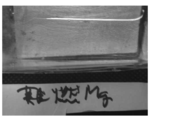
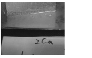
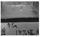
- the structural example of a magnesium fuel cell is shown. It is a photograph which shows a mode when the sample 1 is immersed in 18 weight% salt water. It is a photograph which shows a mode when the sample 3 is immersed in 18 weight% salt water. It is a photograph which shows a mode when the sample 4 is immersed in 18 weight% salt water. It is a photograph which shows the state of the surface of the sample 1 after being immersed in 18% salt water for 122 hours. It is a photograph which shows the state of the surface of the sample 2 after being immersed in 18% salt water for 122 hours. It is a graph which shows the change of a voltage, an electric current, and electric energy when an electric current is sent with the battery of the conditions 1 for 14 days (336 hours).
- FIG. It is a graph which shows the change of an electric current when an electric current is sent with the battery of the conditions 7.
- FIG. It is a graph which shows the change of electric energy when an electric current is sent with the battery of condition 7.
- FIG. It is a graph which shows the change of electric energy when an electric current is sent with the battery of condition 8.
- FIG. 6 is a photograph showing the state of the surface of a negative electrode material (magnesium alloy) after a current is passed by a battery of condition 8.
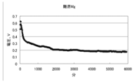
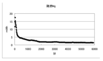
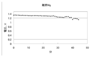
- the voltage change of the flame-retardant Mg battery which uses six carbon plates made from activated carbon as a positive electrode is shown.
- the generated voltage of the flame-retardant Mg battery when a platinum catalyst is used is shown.
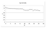
- the generated voltage of the Mg-3Al-0.2Mn battery when a platinum catalyst is used is shown.
- the magnesium fuel cell of the present invention includes a negative electrode material made of a magnesium alloy containing aluminum and calcium.
- the “magnesium fuel cell” is, for example, a magnesium air battery, in which oxygen in the air is a positive electrode active material (a material that receives electrons), and magnesium is a negative electrode active material (a material that emits electrons). It is a battery. Magnesium in the negative electrode emits electrons to become magnesium ions and elutes into the electrolyte. On the other hand, in the positive electrode, oxygen and water receive electrons and become hydroxide ions.
- magnesium hydroxide Mg (OH) 2
- the respective reaction formulas at the positive electrode and the negative electrode are as follows.
- FIG. 1 is a diagram showing a configuration of a magnesium fuel cell 10 (hereinafter, simply referred to as a cell 10) according to an embodiment of the present invention.
- a battery 10 includes a negative electrode material 12 made of a magnesium alloy, a positive electrode current collector 16 that supplies electrons to air (oxygen) as a positive electrode material, a negative electrode material 12, and a positive electrode current collector 16. , A separator 14 disposed between them, an electrolytic solution 18 for eluting magnesium ions (Mg 2+ ) generated in the negative electrode, and an electrolytic solution tank 20 for storing the electrolytic solution 18.
- a battery 10 includes a negative electrode material 12 made of a magnesium alloy, a positive electrode current collector 16 that supplies electrons to air (oxygen) as a positive electrode material, a negative electrode material 12, and a positive electrode current collector 16.
- a separator 14 disposed between them, an electrolytic solution 18 for eluting magnesium ions (Mg 2+ ) generated in the negative electrode, and an electrolytic solution tank 20
- the negative electrode material 12 is made of a magnesium alloy.
- the magnesium alloy is an alloy containing magnesium (Mg) as a main component, for example, an alloy containing 50% by weight or more of magnesium.
- Mg—Al, Mg—Mn, Mg—Zn, Mg—Al—Zn, Mg—Zn—Zr, etc. are known.
- the content of aluminum (Al) in the magnesium alloy is not particularly limited, but is preferably 3% by weight or more and 9% by weight or less, and more preferably 5% by weight or more and 7% by weight with respect to the entire magnesium alloy. % Or less, and most preferably 6% by weight.
- the content of calcium (Ca) in the magnesium alloy is not particularly limited, but is preferably 1% by weight or more and 3% by weight or less, more preferably 1.5% by weight or more with respect to the entire magnesium alloy. It is 2.5 wt% or less, and most preferably 2 wt%.
- An element other than aluminum and calcium may be added to the magnesium alloy.
- other elements such as Zn, Mn, Si, Cu, Li, Na, K, Fe, Ni, Ti, and Zr may be added. These elements can be added at a ratio of, for example, 1% by weight or less with respect to the entire magnesium alloy.
- Zn can be added at a ratio of, for example, 2% by weight or less with respect to the entire magnesium alloy.
- the shape of the magnesium alloy used as the negative electrode material 12 is not particularly limited, and for example, a magnesium alloy processed into a plate shape, a granular shape, or a powder shape can be used. Note that when a magnesium alloy is processed into a granular or powder form, the normal magnesium alloy may easily ignite. In this respect, the magnesium alloy used in the present invention contains aluminum and calcium, has extremely high flame retardancy, and is highly safe because it does not easily ignite even when processed into a granular or powder form.
- a magnesium alloy containing aluminum (Al) and calcium (Ca) is used.
- a magnesium alloy having such a composition has appropriate reactivity and is excellent as a battery material.
- the magnesium alloy of such a composition has the capability to suppress combustion (ability to suppress reaction), and is highly valuable as an industrial material.
- the magnesium alloy used in the present invention can exhibit excellent performance as a battery material due to the synergistic effect of these conflicting characteristics.
- a magnesium alloy containing aluminum and calcium usually has a multilayer structure composed of two phases of a metallic Mg phase (solid solution) and a compound phase (Al 2 Ca). Because the compound phase is relatively inert, the alloy is less reactive macroscopically. This is confirmed by experience.
- the production method of the magnesium alloy used as the negative electrode material 12 is not particularly limited, and for example, it can be produced using the method disclosed in JP-A-10-280062.
- the separator 14 is disposed between the negative electrode material 12 and the positive electrode current collector 16.
- the separator 14 serves to prevent a short circuit between the negative electrode material 12 and the positive electrode current collector 16 and to suck up the electrolytic solution 18 stored in the electrolytic solution tank 20 and hold the electrolytic solution 18. Yes.
- limit especially as the separator 14, For example, a polyethylene fiber, a polypropylene fiber, glass fiber, a resin nonwoven fabric, a glass nonwoven fabric, a filter paper etc. can be used.
- the positive electrode current collector 16 has a role of supplying electrons to oxygen in the air as the positive electrode material.
- the material of the positive electrode current collector 16 is not particularly limited as long as it is a conductive material.
- a carbonaceous material such as activated carbon, carbon fiber, or carbon felt, or a metal material such as iron or copper is used. Can be used.
- the material of the positive electrode current collector 16 it is particularly preferable to use carbon powder from the viewpoint of a large contact area with oxygen in the air and excellent current collection efficiency.
- the electrolytic solution 18 has a role of eluting magnesium ions (Mg 2+ ) generated in the negative electrode material 12 and supplying water (H 2 O) that reacts with oxygen to the positive electrode.
- an acidic, alkaline, or neutral aqueous solution can be used.
- at least one selected from the group consisting of a sodium chloride aqueous solution, a sodium hydroxide aqueous solution, a sodium hydrogen carbonate aqueous solution, and a sodium percarbonate aqueous solution can be used.
- an aqueous solution of fluoride, an aqueous solution containing halogen, or the like can be used.
- an aqueous solution of polyvalent carboxylic acid as disclosed in JP 2010-182435 A can be used.
- the shape and material of the electrolytic solution tank 20 are not particularly limited, and any material can be used as long as the electrolytic solution 18 can be stored.
- a container formed of a synthetic resin such as polypropylene can be used as the electrolytic solution tank 20.
- a wire made of a conductive material such as copper may be attached to the surface of the positive electrode current collector 16 on the side in contact with air. Thereby, the contact area between oxygen and the positive electrode current collector 16 can be increased, and the current collection efficiency at the positive electrode of the battery 10 can be further increased.
- the battery 10 is configured by sequentially laminating the negative electrode material 12, the separator 14, and the positive electrode current collector 16, but the configuration of the battery 10 is as described above. It is not limited to.
- the battery 10 can also be configured by winding the separator 14 and the positive electrode current collector 16 in order around the plate-like negative electrode material 12.
- Example 1 In Example 1, a test was conducted in which magnesium alloys having various compositions were immersed in salt water.
- Sample 1 Magnesium alloy containing 6 wt% Al and 2 wt% Ca
- Sample 2 Magnesium alloy containing 6 wt% Al
- Sample 3 Magnesium alloy containing 2 wt%
- Sample 4 Magnesium alloy containing 5 wt%
- Sample 5 Simple magnesium metal with a purity of 99.95%
- the magnesium alloy containing aluminum and calcium (sample 1) has a significantly higher dissolution rate in salt water than the simple magnesium metal (sample 5) or other magnesium alloys (samples 2 to 4). It turned out to be small. That is, it has been found that by using the negative electrode material 12 made of a magnesium alloy containing aluminum and calcium, the self-discharge of the negative electrode material 12 in the electrolytic solution 18 (brine) can be almost certainly prevented.
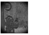
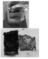
- FIG. 5 is a photograph showing the state of the surface of Sample 1 after being immersed in 18% salt water for 122 hours.
- FIG. 6 is a photograph showing the state of the surface of Sample 2 after being immersed in 18% salt water for 122 hours. The amount of reduction for each sample was 19 mg for sample 1 and 295 mg for sample 2.
- This film is probably a film made of calcium chloride (CaCl 2 ) or MgCl 2 + CaCl 2 , and it is assumed that dissolution of the sample surface was prevented by this film. And, this film is made of a magnesium alloy as described later for the reason that the film is weak, there are gaps in the film, and the film is conductive (or any one of them). Only when used as a negative electrode material, there is an effect of dissolving a magnesium alloy little by little in salt water, and it is presumed that a current close to the theoretical value could be generated from the magnesium alloy. In addition, such consideration is a guess of the present inventors based on present knowledge, and does not restrict
- Example 2 In Example 2, an experiment was conducted in which a magnesium fuel cell was manufactured under the following conditions 1 to 5 and current was supplied to the motor.
- Negative electrode material Magnesium alloy containing 6% by weight of Al and 2% by weight of Ca Positive electrode current collector: Thick carbon fiber cloth Electrolyte: 18% by weight salt water (Condition 2) Negative electrode material: Magnesium alloy containing 6 wt% Al and 2 wt% Ca Positive electrode current collector: Thin carbon fiber cloth Electrolyte: 18 wt% salt water (Condition 3) Negative electrode material: Magnesium alloy containing 6% by weight of Al and 2% by weight of Ca Positive electrode current collector: Carbon felt Electrolyte: Concentrated seawater (sodium chloride concentration 18% by weight) (Condition 4) Negative electrode material: Magnesium alloy containing 6% by weight of Al and 2% by weight of Ca Positive electrode current collector: Carbon felt Electrolyte: Seawater (Condition 5) Negative electrode material: Magnesium alloy containing 6% by weight of Al and 2% by weight of Ca Positive electrode current collector: Carbon felt Electrolyte: Seawater (Condition 5) Negative electrode material: Magne
- FIG. 7 is a graph showing changes in voltage, current, and electric energy when current is passed for 14 days (336 hours) by the battery of condition 1.
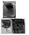
- FIG. 8 is a photograph showing the state of the positive electrode current collector and the negative electrode material (magnesium alloy) after a current was passed for 14 days by the battery of Condition 1.
- the results of the experiment for 14 days under Condition 1 were an average voltage of 0.251 v, an average current of 11.6 mA, an average power of 3.08 mW, a total current of 3890 mAh, and a total power of 1036 mWh.
- FIG. 9 is a graph showing changes in voltage, current, and electric energy when current is passed for 14 days (336 hours) by the battery of condition 2.
- FIG. 10 is a photograph showing the state of the positive electrode current collector and the negative electrode material (magnesium alloy) after a current was passed for 14 days by the battery of Condition 2. The results of the experiment for 14 days under condition 2 were an average voltage of 0.223 v, an average current of 10.28 mA, an average power of 2.59 mW, a total current of 3456 mAh, and a total power of 869 mWh.
- FIG. 11 is a graph showing changes in voltage, current, and electric energy when current is passed for 14 days (336 hours) by the battery of condition 3.
- FIG. 12 is a photograph showing the state of the positive electrode current collector and the negative electrode material (magnesium alloy) after a current was passed for 14 days by the battery of Condition 3.
- the results of the experiment for 14 days under Condition 3 were an average voltage of 0.344 v, an average current of 15.71 mA, an average power of 6.75 mW, a total current of 5751 mAh, and a total power of 2471 mWh.
- FIG. 13 is a graph showing changes in voltage, current, and electric energy when current is passed for 14 days (336 hours) by the battery of condition 4.
- FIG. 14 is a photograph showing the state of the positive electrode current collector and the negative electrode material (magnesium alloy) after a current was passed for 14 days by the battery of Condition 4.
- the results of the experiment for 14 days under Condition 4 were an average voltage of 0.213 v, an average current of 9.76 mA, an average power of 2.42 mW, a total current of 3574 mAh, and a total power of 886 mWh.
- FIG. 15 is a graph showing changes in voltage, current, and electric energy when current is passed for 14 days (336 hours) by the battery of condition 5.
- FIG. 16 is a photograph showing the state of the positive electrode current collector and the negative electrode material (magnesium alloy) after a current was passed for 14 days by the battery of Condition 5.
- the sodium hydroxide aqueous solution is used as the electrolytic solution for the first four days, and then the experiment is performed by adding seawater to the electrolytic solution. For this reason, no current is generated for the first 4 days, and current is generated only for 10 days after the addition of seawater.
- the results of the experiment for 10 days after adding seawater under Condition 5 were an average voltage of 0.361 v, an average current of 16.27 mA, an average power of 6.52 mW, a total current of 3940 mAh, and a total power of 1579 mWh.
- Example 2 From the experimental results of Example 2, the following knowledge was obtained. (1) The battery prepared under the above five conditions was able to maintain the electromotive force for 14 days. During that time, the total current was 3456 mAh to 5751 mAh, and the total power generation amount was 869 mWh to 2471 mWh. (2) The battery using seawater concentrated to the same concentration as the electrolyte solution was able to generate a larger voltage and current than the 18% salt water. (3) A battery using a solution obtained by adding seawater to an aqueous sodium hydroxide solution as an electrolyte could generate a larger voltage and current than other batteries.
- Example 3 In Example 3, an experiment was conducted in which a magnesium fuel cell was manufactured under the following conditions 6 to 8 and current was supplied to the motor. In Example 3, one surface of a plate-like magnesium alloy was covered with a tape and only one surface of the magnesium alloy was exposed as the negative electrode material.
- Negative electrode material Magnesium alloy containing 6 wt% Al and 2 wt% Ca Positive electrode current collector: Carbon felt Electrolyte: 18 wt% salt water (Condition 7) Negative electrode material: Magnesium alloy containing 6 wt% Al and 0.3 wt% Mn Positive electrode current collector: Carbon felt Electrolyte: 18 wt% salt water (Condition 8) Negative electrode material: Magnesium alloy containing 2 wt% of Ca Positive electrode current collector: Carbon felt Electrolyte: 18 wt% salt water
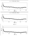
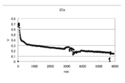
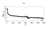
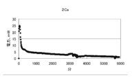
- FIG. 17 to 19 are graphs showing changes in voltage, current, and electric energy when a current is passed for 100 hours by the battery of condition 6.
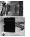
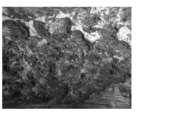
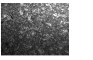
- FIG. FIG. 20 is a photograph showing the state of the surface of the negative electrode material (magnesium alloy) after a current is passed by the battery of condition 6.
- the amount of decrease in the negative electrode material (magnesium alloy) was 0.601 g
- the amount of current per gram of magnesium alloy was 1630 mAh / g
- the amount of power was 476 mWh / g. there were.
- the surface of the negative electrode material (magnesium alloy) was corroded to a substantially uniform depth throughout.
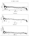
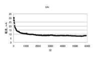
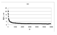
- FIG. 21 to 23 are graphs showing changes in voltage, current, and electric energy when a current is passed for 100 hours by the battery of condition 7.
- FIG. FIG. 24 is a photograph showing the state of the surface of the negative electrode material (magnesium alloy) after a current is passed by the battery of condition 7.
- the decrease amount of the negative electrode material (magnesium alloy) was 0.781 g
- the current amount per 1 g of magnesium alloy was 1181 mAh / g
- the electric energy was 273 mWh / g. there were.
- the surface of the negative electrode material (magnesium alloy) was in a state of being deeply corroded locally.
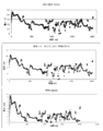
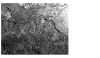
- FIG. 25 to 27 are graphs showing changes in voltage, current, and electric energy when a current is passed for 100 hours by the battery of condition 8.
- FIG. FIG. 28 is a photograph showing the state of the surface of the negative electrode material (magnesium alloy) after a current is passed by the battery of condition 8.
- the decrease amount of the negative electrode material (magnesium alloy) was 1.597 g
- the current amount per 1 g of the magnesium alloy was 733 mAh / g
- the electric energy was 200 mWh / g. there were.
- the surface of the negative electrode material (magnesium alloy) was in a state of being deeply corroded.
- Example 3 From the experimental results of Example 3, it was found that the battery of condition 6 can extract more current than the batteries of condition 7 and condition 8. From this result, it was found that when a magnesium alloy containing aluminum and calcium is used as a negative electrode material, electricity can be stably taken out over a long period of time compared to the case where a conventional magnesium alloy is used.
- the electric capacity (Ah / g ) is a value obtained from the atomic weight of the metal, the number of charges of the ions, and the charge of the electrons, and directly reflects the characteristics of the metal electrode.
- the theoretical electrical capacity of pure magnesium is 2.2 Ah / g .
- the magnesium alloy used in the present invention contains, for example, 92% by weight of magnesium.
- the electric capacity of this magnesium alloy is, for example, 1.63 Ah / g as described above.
- the magnesium alloy used in the present invention can extract electricity of about 80% of the theoretical electric capacity, and can extract electricity with high efficiency.
- the energy density is related to the voltage generated in the battery.
- the magnesium battery may be able to obtain a potential of 2.37V.
- the voltage generated in the battery and thus the available energy density is greatly influenced by the characteristics of the positive electrode.
- oxygen in the air is a positive electrode material, how to efficiently extract the charge by reacting magnesium ions with oxygen becomes a problem.
- the energy density is affected by the material, catalyst, structure, and the like of the positive electrode (air electrode) as well as the performance of the metal electrode (negative electrode).
- a battery was prepared under the same conditions as in the above condition 6 except that 6 parallel carbon plates having a diameter of 5 cm were used as the positive electrode.
- the voltage characteristics of this battery are shown in FIG.
- the characteristics of the air electrode (positive electrode) can be remarkably enhanced by using a catalyst.
- a battery was produced under the same conditions as in the above Condition 6 except that a positive electrode obtained by supporting a small amount of platinum on foamed Ni and applying activated carbon thereon was used.
- the voltage characteristics of this battery are shown in FIG.
- FIG. 31 shows the voltage characteristics of this battery.
Landscapes
- Chemical & Material Sciences (AREA)
- Chemical Kinetics & Catalysis (AREA)
- Electrochemistry (AREA)
- General Chemical & Material Sciences (AREA)
- Engineering & Computer Science (AREA)
- Manufacturing & Machinery (AREA)
- Materials Engineering (AREA)
- Mechanical Engineering (AREA)
- Metallurgy (AREA)
- Organic Chemistry (AREA)
- Hybrid Cells (AREA)
- Battery Electrode And Active Subsutance (AREA)
Abstract
Description
本発明のマグネシウム燃料電池は、アルミニウム及びカルシウムを含むマグネシウム合金からなる負極材を備えることを特徴とする。ここで、「マグネシウム燃料電池」とは、例えばマグネシウム空気電池のことであり、空気中の酸素を正極活物質(電子を受け取る物質)とし、マグネシウムを負極活物質(電子を放出する物質)とする電池のことである。負極のマグネシウムは、電子を放出してマグネシウムイオンとなって電解液中に溶出する。一方、正極では、酸素と水が電子を受け取って水酸化物イオンとなる。電池全体で見ると、マグネシウム、酸素、及び水から水酸化マグネシウム(Mg(OH)2)が生成することで両極間に起電力が発生する。正極及び負極でのそれぞれの反応式は、以下の通りとなる。
負極:2Mg → 2Mg2++4e-
全体:2Mg+O2+2H2O → 2Mg(OH)2↓
図1に示すように、電池10は、マグネシウム合金からなる負極材12と、正極材としての空気(酸素)に電子を供給する正極集電体16と、負極材12と正極集電体16との間に配置されるセパレータ14と、負極で発生したマグネシウムイオン(Mg2+)を溶出させるための電解液18と、電解液18を貯留しておくための電解液槽20とを備えている。
なお、マグネシウム合金を粒状あるいは粉状に加工した場合、通常のマグネシウム合金は容易に発火してしまうおそれがある。この点、本発明において用いるマグネシウム合金はアルミニウム及びカルシウムを含んでおり、難燃性が極めて高く、粒状あるいは粉状に加工した場合であっても容易に発火しないために安全性が高い。
なお、このような推測は、本発明の範囲を何ら制限するものではない。
実施例1では、様々な組成のマグネシウム合金を塩水中に浸漬させる試験を行った。
サンプル1:Alを6重量%、Caを2重量含むマグネシウム合金
サンプル2:Alを6重量%含むマグネシウム合金
サンプル3:Caを2重量%含むマグネシウム合金
サンプル4:Caを5重量%含むマグネシウム合金
サンプル5:純度99.95%の単体マグネシウム金属
この結果、サンプル1については、塩水中でほとんど溶解しなかった。一方、サンプル5については、塩水中で水素を激しく発生しながら溶解した。サンプル2~4についても、塩水中で水素を発生しながら溶解した。図2~図4に、これらの様子を写真で示す。
サンプル1<サンプル2<サンプル3<サンプル4<サンプル5
なお、このような考察は、現時点での知見に基づく本発明者らの推測であり、本発明の範囲を何ら制限するものではない。
実施例2では、以下の条件1~5でマグネシウム燃料電池を作製してモータに電流を流す実験を行った。
負極材 :Alを6重量%、Caを2重量%含むマグネシウム合金
正極集電体:厚い炭素繊維布
電解液 :18重量%塩水
(条件2)
負極材 :Alを6重量%、Caを2重量%含むマグネシウム合金
正極集電体:薄い炭素繊維布
電解液 :18重量%塩水
(条件3)
負極材 :Alを6重量%、Caを2重量%含むマグネシウム合金
正極集電体:カーボンフェルト
電解液 :濃縮海水(塩化ナトリウム濃度18重量%)
(条件4)
負極材 :Alを6重量%、Caを2重量%含むマグネシウム合金
正極集電体:カーボンフェルト
電解液 :海水
(条件5)
負極材 :Alを6重量%、Caを2重量%含むマグネシウム合金
正極集電体:カーボンフェルト
電解液 :海水+NaOH水溶液
条件1での14日間の実験の結果は、平均電圧0.251v、平均電流11.6mA、平均電力3.08mW、総電流3890mAh、総電力1036mWhであった。
条件2での14日間の実験の結果は、平均電圧0.223v、平均電流10.28mA、平均電力2.59mW、総電流3456mAh、総電力869mWhであった。
条件3での14日間の実験の結果は、平均電圧0.344v、平均電流15.71mA、平均電力6.75mW、総電流5751mAh、総電力2471mWhであった。
条件4での14日間の実験の結果は、平均電圧0.213v、平均電流9.76mA、平均電力2.42mW、総電流3574mAh、総電力886mWhであった。
条件5で海水を追加した後の10日間の実験の結果は、平均電圧0.361v、平均電流16.27mA、平均電力6.52mW、総電流3940mAh、総電力1579mWhであった。
(1)上記5つの条件で作成した電池は、14日間起電力を維持することができた。その間の総電流は3456mAh~5751mAhであり、総発電量は869mWh~2471mWhであった。
(2)18%の塩水よりも、それと同濃度に濃縮した海水を電解液として用いた電池の方が、より大きい電圧及び電流を発生することができた。
(3)水酸化ナトリウム水溶液に海水を追加した溶液を電解液として用いた電池は、他の電池よりも大きな電圧及び電流を発生することができた。
実施例3では、以下の条件6~8でマグネシウム燃料電池を作製してモータに電流を流す実験を行った。なお、この実施例3では、板状のマグネシウム合金の片面をテープで被覆して、マグネシウム合金の一方の面だけを露出したものを負極材として用いた。
負極材 :Alを6重量%、Caを2重量%含むマグネシウム合金
正極集電体:カーボンフェルト
電解液 :18重量%塩水
(条件7)
負極材 :Alを6重量%、Mnを0.3重量%含むマグネシウム合金
正極集電体:カーボンフェルト
電解液 :18重量%塩水
(条件8)
負極材 :Caを2重量%含むマグネシウム合金
正極集電体:カーボンフェルト
電解液 :18重量%塩水
条件6の電池によって電流を流す実験の結果は、負極材(マグネシウム合金)の減少量が0.601gであり、マグネシウム合金1g当たりの電流量が1630mAh/gであり、電力量が476mWh/gであった。
また、図20を見れば分かる通り、負極材(マグネシウム合金)の表面は全面的にほぼ均一の深さに腐食した状態であった。
条件7の電池によって電流を流す実験の結果は、負極材(マグネシウム合金)の減少量が0.781gであり、マグネシウム合金1g当たりの電流量が1181mAh/gであり、電力量が273mWh/gであった。
また、図24を見れば分かる通り、負極材(マグネシウム合金)の表面は局部的に深く腐食した状態であった。
条件8の電池によって電流を流す実験の結果は、負極材(マグネシウム合金)の減少量が1.597gであり、マグネシウム合金1g当たりの電流量が733mAh/gであり、電力量が200mWh/gであった。
また、図28を見れば分かる通り、負極材(マグネシウム合金)の表面は全面的に深く腐食した状態であった。
しかしながら、電池で発生する電圧、従って利用できるエネルギー密度は、正極の特性に大きく影響される。特に、燃料電池は、空気中の酸素が正極物質であるため、いかにマグネシウムイオンを酸素と反応させて、効率よく電荷を取り出すかが課題となる。
このために、エネルギー密度は、金属極(負極)の性能と同様に、正極(空気極)の材質、触媒、構造などの影響を受ける。
10 マグネシウム燃料電池
12 負極材
14 セパレータ
16 正極集電体
18 電解液
20 電解液槽
Claims (3)
- マグネシウム合金からなる負極材と、
前記負極材からマグネシウムイオンを溶出させる電解液と、を備え、
前記マグネシウム合金は、アルミニウム及びカルシウムを含むことを特徴とするマグネシウム燃料電池。 - 前記マグネシウム合金には、アルミニウムが3重量%以上9重量%以下、カルシウムが1重量%以上3重量%以下含まれている請求項1に記載のマグネシウム燃料電池。
- 前記電解液は、塩化ナトリウム水溶液、水酸化ナトリウム水溶液、炭酸水素ナトリウム水溶液、及び過炭酸ナトリウム水溶液からなる群から選ばれる少なくとも1つである請求項1または請求項2に記載のマグネシウム燃料電池。
Priority Applications (4)
| Application Number | Priority Date | Filing Date | Title |
|---|---|---|---|
| US14/112,068 US9461305B2 (en) | 2011-04-18 | 2012-03-27 | Magnesium alloy fuel cell |
| CN201280019230.1A CN103493286A (zh) | 2011-04-18 | 2012-03-27 | 镁燃料电池 |
| EP12774327.6A EP2701232B1 (en) | 2011-04-18 | 2012-03-27 | Magnesium fuel cell |
| KR1020137027986A KR101964895B1 (ko) | 2011-04-18 | 2012-03-27 | 마그네슘 연료전지 |
Applications Claiming Priority (2)
| Application Number | Priority Date | Filing Date | Title |
|---|---|---|---|
| JP2011092297 | 2011-04-18 | ||
| JP2011-092297 | 2011-04-18 |
Publications (1)
| Publication Number | Publication Date |
|---|---|
| WO2012144301A1 true WO2012144301A1 (ja) | 2012-10-26 |
Family
ID=47041417
Family Applications (1)
| Application Number | Title | Priority Date | Filing Date |
|---|---|---|---|
| PCT/JP2012/057972 Ceased WO2012144301A1 (ja) | 2011-04-18 | 2012-03-27 | マグネシウム燃料電池 |
Country Status (6)
| Country | Link |
|---|---|
| US (1) | US9461305B2 (ja) |
| EP (1) | EP2701232B1 (ja) |
| JP (5) | JP5629864B2 (ja) |
| KR (1) | KR101964895B1 (ja) |
| CN (1) | CN103493286A (ja) |
| WO (1) | WO2012144301A1 (ja) |
Cited By (2)
| Publication number | Priority date | Publication date | Assignee | Title |
|---|---|---|---|---|
| CN103022539A (zh) * | 2012-12-14 | 2013-04-03 | 山西省精工镁技术研究所 | 通过改变电极板插入数量来改变输出电量的镁燃料电池 |
| JP2015060838A (ja) * | 2013-09-18 | 2015-03-30 | 台湾カーボンナノチューブテクノロジー股▲ふん▼有限公司 | 海水発電システム |
Families Citing this family (22)
| Publication number | Priority date | Publication date | Assignee | Title |
|---|---|---|---|---|
| JP5737727B2 (ja) * | 2012-12-27 | 2015-06-17 | 株式会社東洋製作所 | マグネシウム電池 |
| JP5799980B2 (ja) | 2013-06-12 | 2015-10-28 | コニカミノルタ株式会社 | マグネシウム電池およびマグネシウム電池システム |
| JP2015046312A (ja) * | 2013-08-28 | 2015-03-12 | 古河電池株式会社 | マグネシウム電池 |
| JP5684929B1 (ja) * | 2014-01-31 | 2015-03-18 | 古河電池株式会社 | 金属空気電池 |
| WO2015076172A1 (ja) * | 2013-11-19 | 2015-05-28 | 古河電池株式会社 | 金属空気電池、および金属空気電池ユニット |
| JP6496479B2 (ja) * | 2013-12-09 | 2019-04-03 | 堅一 内藤 | 再生可能エネルギ搬送再生方法 |
| CN103872300B (zh) * | 2014-03-26 | 2016-03-30 | 苏州绿电能源科技有限公司 | 金属燃料电池用阳极材料及其制法和应用 |
| WO2016056549A1 (ja) * | 2014-10-06 | 2016-04-14 | ワイティーエス・サイエンス・プロパティーズ・プライベート・リミテッド | マグネシウム燃料体、マグネシウム空気電池、電子機器、及びマグネシウム空気電池の使用方法 |
| JP6595754B2 (ja) * | 2014-12-01 | 2019-10-23 | 株式会社BlueForce | 金属空気電池 |
| JP6523689B2 (ja) * | 2015-01-14 | 2019-06-05 | 株式会社戸畑製作所 | 一次電池負極用合金 |
| CN105098200A (zh) * | 2015-06-01 | 2015-11-25 | 爱能新能源技术(天津)有限公司 | 一种用于金属空气燃料电池的阴极包及其应用 |
| JP6281532B2 (ja) * | 2015-07-13 | 2018-02-21 | トヨタ自動車株式会社 | 金属空気電池用電解液、及び、金属空気電池 |
| JP2017037815A (ja) * | 2015-08-12 | 2017-02-16 | 株式会社 巽中央経營研究所 | 非常用電源による通電システム |
| TWI695534B (zh) * | 2017-12-05 | 2020-06-01 | 廖國明 | 可攜式水致動發電裝置 |
| JP7344487B2 (ja) * | 2018-07-13 | 2023-09-14 | 日本金属株式会社 | 電気化学デバイス用電極材およびその製造方法 |
| CN109192991B (zh) * | 2018-08-21 | 2021-10-15 | 广州理文科技有限公司 | 一种石墨烯复合金属空气电池的制备方法 |
| CN109037663B (zh) * | 2018-09-21 | 2021-05-28 | 武汉中原长江科技发展有限公司 | 一种聚苯胺/金属氧化物/碳纤维复合正极及海水电池和复合正极的制备方法 |
| CN109841931B (zh) * | 2019-03-04 | 2024-01-09 | 成都天智轻量化科技有限公司 | 一种氯镁燃料电池 |
| JP7362164B2 (ja) * | 2020-02-21 | 2023-10-17 | 国立研究開発法人物質・材料研究機構 | Mg基合金負極材及びその製造方法、並びにこれを用いたMg二次電池 |
| JP2023157724A (ja) * | 2022-04-15 | 2023-10-26 | 国立大学法人富山大学 | マグネシウム合金からなる蓄電池用の電極材料及び電極材の製造方法 |
| US20250343303A1 (en) * | 2022-05-31 | 2025-11-06 | Nippon Telegraph And Telephone Corporation | Magnesium Air Battery and Manufacturing Method of It |
| CN116356305B (zh) * | 2023-03-27 | 2025-04-15 | 上海交通大学 | 一种镁空气电池镁负极表面改性方法 |
Citations (6)
| Publication number | Priority date | Publication date | Assignee | Title |
|---|---|---|---|---|
| JPS566384A (en) * | 1979-06-28 | 1981-01-22 | Yuasa Battery Co Ltd | Air-magnesium cell |
| JPH10280062A (ja) | 1997-04-02 | 1998-10-20 | Agency Of Ind Science & Technol | マグネシウム合金の精製方法 |
| JP2004537151A (ja) | 2001-08-01 | 2004-12-09 | マグパワー・システムズ・インコーポレイテッド | 電池/燃料セルの性能を向上させるための方法および生成物 |
| JP2010182435A (ja) | 2009-02-03 | 2010-08-19 | Suzuki Senkei | マグネシウム電池 |
| JP2011181382A (ja) * | 2010-03-02 | 2011-09-15 | Shigeru Moriyama | マグネシウム空気電池 |
| JP2012038666A (ja) * | 2010-08-10 | 2012-02-23 | Aqumo Co Ltd | マグネシウム電池 |
Family Cites Families (14)
| Publication number | Priority date | Publication date | Assignee | Title |
|---|---|---|---|---|
| US3849868A (en) * | 1969-08-01 | 1974-11-26 | Texas Instruments Inc | Method of making magnesium anode battery |
| FR2642439B2 (ja) | 1988-02-26 | 1993-04-16 | Pechiney Electrometallurgie | |
| NZ230197A (en) * | 1988-08-09 | 1990-11-27 | Alcan Int Ltd | Aluminium battery with an aluminium alloy anode and containing tin in the anode and/or the electrolyte |
| JPH0636766A (ja) * | 1992-07-21 | 1994-02-10 | Sanyo Electric Co Ltd | 電 池 |
| JP2000012016A (ja) * | 1998-06-22 | 2000-01-14 | Matsushita Electric Ind Co Ltd | 電池用負極およびその製造方法 |
| JP3030338B1 (ja) * | 1998-10-05 | 2000-04-10 | 工業技術院長 | 高強度難燃性マグネシウム合金の製造方法 |
| JP2001283796A (ja) * | 2000-04-04 | 2001-10-12 | Matsushita Electric Ind Co Ltd | リチウム二次電池とその製造方法 |
| JP4415098B2 (ja) * | 2005-03-16 | 2010-02-17 | 独立行政法人産業技術総合研究所 | 難燃性マグネシウム合金押出材の製造方法及びその押出材 |
| WO2007116872A1 (ja) * | 2006-04-03 | 2007-10-18 | Tsc Co., Ltd. | 水発電用合金、前記合金を用いる水発電装置、及び水発電方法 |
| JP5035893B2 (ja) * | 2006-09-01 | 2012-09-26 | 独立行政法人産業技術総合研究所 | 高強度高延性難燃性マグネシウム合金及びその製造方法 |
| JP2008106337A (ja) * | 2006-10-27 | 2008-05-08 | Shingijutsu Kenkyusho:Kk | マグネシウム合金の圧延材およびその製造方法 |
| CN101026255A (zh) * | 2007-02-08 | 2007-08-29 | 马润芝 | 改性铝、镁合金燃料电池 |
| JP5405392B2 (ja) * | 2009-06-17 | 2014-02-05 | 株式会社豊田中央研究所 | 再生マグネシウム合金とその製造方法およびマグネシウム合金 |
| CN102005577B (zh) * | 2010-09-30 | 2013-01-16 | 马润芝 | 一种镁合金燃料电池的阳极及其制备方法 |
-
2012
- 2012-03-27 KR KR1020137027986A patent/KR101964895B1/ko not_active Expired - Fee Related
- 2012-03-27 US US14/112,068 patent/US9461305B2/en not_active Expired - Fee Related
- 2012-03-27 WO PCT/JP2012/057972 patent/WO2012144301A1/ja not_active Ceased
- 2012-03-27 EP EP12774327.6A patent/EP2701232B1/en not_active Not-in-force
- 2012-03-27 CN CN201280019230.1A patent/CN103493286A/zh active Pending
- 2012-03-27 JP JP2012071644A patent/JP5629864B2/ja not_active Expired - Fee Related
-
2014
- 2014-05-14 JP JP2014100605A patent/JP5676802B2/ja not_active Expired - Fee Related
- 2014-05-14 JP JP2014100606A patent/JP5671641B2/ja not_active Expired - Fee Related
- 2014-12-22 JP JP2014259337A patent/JP5825649B2/ja not_active Expired - Fee Related
-
2015
- 2015-03-13 JP JP2015050559A patent/JP5876950B2/ja not_active Expired - Fee Related
Patent Citations (6)
| Publication number | Priority date | Publication date | Assignee | Title |
|---|---|---|---|---|
| JPS566384A (en) * | 1979-06-28 | 1981-01-22 | Yuasa Battery Co Ltd | Air-magnesium cell |
| JPH10280062A (ja) | 1997-04-02 | 1998-10-20 | Agency Of Ind Science & Technol | マグネシウム合金の精製方法 |
| JP2004537151A (ja) | 2001-08-01 | 2004-12-09 | マグパワー・システムズ・インコーポレイテッド | 電池/燃料セルの性能を向上させるための方法および生成物 |
| JP2010182435A (ja) | 2009-02-03 | 2010-08-19 | Suzuki Senkei | マグネシウム電池 |
| JP2011181382A (ja) * | 2010-03-02 | 2011-09-15 | Shigeru Moriyama | マグネシウム空気電池 |
| JP2012038666A (ja) * | 2010-08-10 | 2012-02-23 | Aqumo Co Ltd | マグネシウム電池 |
Non-Patent Citations (1)
| Title |
|---|
| See also references of EP2701232A4 |
Cited By (2)
| Publication number | Priority date | Publication date | Assignee | Title |
|---|---|---|---|---|
| CN103022539A (zh) * | 2012-12-14 | 2013-04-03 | 山西省精工镁技术研究所 | 通过改变电极板插入数量来改变输出电量的镁燃料电池 |
| JP2015060838A (ja) * | 2013-09-18 | 2015-03-30 | 台湾カーボンナノチューブテクノロジー股▲ふん▼有限公司 | 海水発電システム |
Also Published As
| Publication number | Publication date |
|---|---|
| JP2014167933A (ja) | 2014-09-11 |
| JP5876950B2 (ja) | 2016-03-02 |
| JP5825649B2 (ja) | 2015-12-02 |
| US20140220458A1 (en) | 2014-08-07 |
| JP2012234799A (ja) | 2012-11-29 |
| JP2015092491A (ja) | 2015-05-14 |
| EP2701232B1 (en) | 2017-05-03 |
| KR101964895B1 (ko) | 2019-04-02 |
| JP2014187032A (ja) | 2014-10-02 |
| JP5671641B2 (ja) | 2015-02-18 |
| JP2015130358A (ja) | 2015-07-16 |
| JP5676802B2 (ja) | 2015-02-25 |
| US9461305B2 (en) | 2016-10-04 |
| CN103493286A (zh) | 2014-01-01 |
| EP2701232A1 (en) | 2014-02-26 |
| EP2701232A4 (en) | 2014-11-05 |
| KR20140027177A (ko) | 2014-03-06 |
| JP5629864B2 (ja) | 2014-11-26 |
Similar Documents
| Publication | Publication Date | Title |
|---|---|---|
| JP5876950B2 (ja) | マグネシウム燃料電池用負極材 | |
| Hao et al. | Deeply understanding the Zn anode behaviour and corresponding improvement strategies in different aqueous Zn-based batteries | |
| JP5192613B2 (ja) | マグネシウム金属空気電池 | |
| Li et al. | Aluminum as anode for energy storage and conversion: a review | |
| JP5719175B2 (ja) | 充電式ニッケル−亜鉛バッテリ用のペーストされた水酸化ニッケル電極 | |
| US20160028133A1 (en) | Lithium-air battery for electric vehicles and other applications using molten nitrate electrolytes | |
| WO2017099910A1 (en) | Metal-air battery | |
| TW201001784A (en) | Sodium ion based aqueous electrolyte electrochemical secondary energy storage device | |
| JP6314152B2 (ja) | 固体アルカリイオン伝導性膜の劣化防止 | |
| EP3229309B1 (en) | Rechargeable aluminum-air electrochemical cell | |
| CN106688133A (zh) | 用于使过渡金属氰合金属酸盐电极稳定的电解质添加剂 | |
| Davies et al. | Utilization of hyper-dendritic zinc during high rate discharge in alkaline electrolytes | |
| JP2013033639A (ja) | マグネシウム金属イオン電池 | |
| JP6281544B2 (ja) | 金属空気電池用電解液、及び、金属空気電池 | |
| JP2015046312A (ja) | マグネシウム電池 | |
| WO2005011042A1 (ja) | 鉛蓄電池電解液用添加剤および鉛蓄電池 | |
| JP2015046368A (ja) | マグネシウム電池 | |
| KR20230039913A (ko) | 알루미늄 공기전지용 전해액 및 이의 제조 방법 | |
| KR102535066B1 (ko) | 알루미늄 공기전지용 전해액 및 이의 제조 방법 | |
| CN121172297A (zh) | 基于有机阴离子介导的梯度离子泵调控界面反应的电解液 | |
| JP2022173005A (ja) | 塩化亜鉛電池 | |
| JP2019129044A (ja) | 一次電池 | |
| Kim et al. | Comparative study of metal oxide nucleation seeds for highly stable aqueous Zn-ion batteries | |
| JP2015008049A (ja) | 電池用の電解液及び電池用の電解液の製造方法 |
Legal Events
| Date | Code | Title | Description |
|---|---|---|---|
| 121 | Ep: the epo has been informed by wipo that ep was designated in this application |
Ref document number: 12774327 Country of ref document: EP Kind code of ref document: A1 |
|
| REEP | Request for entry into the european phase |
Ref document number: 2012774327 Country of ref document: EP |
|
| WWE | Wipo information: entry into national phase |
Ref document number: 2012774327 Country of ref document: EP |
|
| NENP | Non-entry into the national phase |
Ref country code: DE |
|
| ENP | Entry into the national phase |
Ref document number: 20137027986 Country of ref document: KR Kind code of ref document: A |
|
| WWE | Wipo information: entry into national phase |
Ref document number: 14112068 Country of ref document: US |