WO2012144364A1 - Connecteur - Google Patents
Connecteur Download PDFInfo
- Publication number
- WO2012144364A1 WO2012144364A1 PCT/JP2012/059659 JP2012059659W WO2012144364A1 WO 2012144364 A1 WO2012144364 A1 WO 2012144364A1 JP 2012059659 W JP2012059659 W JP 2012059659W WO 2012144364 A1 WO2012144364 A1 WO 2012144364A1
- Authority
- WO
- WIPO (PCT)
- Prior art keywords
- connector
- cavity
- cavities
- holder
- main body
- Prior art date
- Legal status (The legal status is an assumption and is not a legal conclusion. Google has not performed a legal analysis and makes no representation as to the accuracy of the status listed.)
- Ceased
Links
Images


Classifications
-
- H—ELECTRICITY
- H01—ELECTRIC ELEMENTS
- H01R—ELECTRICALLY-CONDUCTIVE CONNECTIONS; STRUCTURAL ASSOCIATIONS OF A PLURALITY OF MUTUALLY-INSULATED ELECTRICAL CONNECTING ELEMENTS; COUPLING DEVICES; CURRENT COLLECTORS
- H01R13/00—Details of coupling devices of the kinds covered by groups H01R12/70 or H01R24/00 - H01R33/00
- H01R13/46—Bases; Cases
- H01R13/514—Bases; Cases composed as a modular blocks or assembly, i.e. composed of co-operating parts provided with contact members or holding contact members between them
-
- H—ELECTRICITY
- H01—ELECTRIC ELEMENTS
- H01R—ELECTRICALLY-CONDUCTIVE CONNECTIONS; STRUCTURAL ASSOCIATIONS OF A PLURALITY OF MUTUALLY-INSULATED ELECTRICAL CONNECTING ELEMENTS; COUPLING DEVICES; CURRENT COLLECTORS
- H01R13/00—Details of coupling devices of the kinds covered by groups H01R12/70 or H01R24/00 - H01R33/00
- H01R13/46—Bases; Cases
- H01R13/516—Means for holding or embracing insulating body, e.g. casing, hoods
- H01R13/518—Means for holding or embracing insulating body, e.g. casing, hoods for holding or embracing several coupling parts, e.g. frames
-
- H—ELECTRICITY
- H01—ELECTRIC ELEMENTS
- H01R—ELECTRICALLY-CONDUCTIVE CONNECTIONS; STRUCTURAL ASSOCIATIONS OF A PLURALITY OF MUTUALLY-INSULATED ELECTRICAL CONNECTING ELEMENTS; COUPLING DEVICES; CURRENT COLLECTORS
- H01R13/00—Details of coupling devices of the kinds covered by groups H01R12/70 or H01R24/00 - H01R33/00
- H01R13/62—Means for facilitating engagement or disengagement of coupling parts or for holding them in engagement
- H01R13/629—Additional means for facilitating engagement or disengagement of coupling parts, e.g. aligning or guiding means, levers, gas pressure electrical locking indicators, manufacturing tolerances
-
- H—ELECTRICITY
- H01—ELECTRIC ELEMENTS
- H01R—ELECTRICALLY-CONDUCTIVE CONNECTIONS; STRUCTURAL ASSOCIATIONS OF A PLURALITY OF MUTUALLY-INSULATED ELECTRICAL CONNECTING ELEMENTS; COUPLING DEVICES; CURRENT COLLECTORS
- H01R13/00—Details of coupling devices of the kinds covered by groups H01R12/70 or H01R24/00 - H01R33/00
- H01R13/62—Means for facilitating engagement or disengagement of coupling parts or for holding them in engagement
- H01R13/627—Snap or like fastening
- H01R13/6271—Latching means integral with the housing
- H01R13/6272—Latching means integral with the housing comprising a single latching arm
Definitions
- the present invention relates to a connector having a plurality of cavities in which terminal fittings connected to electric wire terminals are accommodated, and more particularly, a connector suitable as a connector to be connected to a plurality of mating connectors provided in each of stacked members. About.
- the electrical / electronic device (member) is provided with a connector for electrical connection to a power source and other electrical / electronic device (member).
- a connector for electrical connection to a power source and other electrical / electronic device (member).
- bus bars and tab terminals are provided on a wiring board in an electrical junction box, and these bus bars and tab terminals are accommodated in a connector housing formed integrally with a main cover that covers the wiring board. The resulting connector is provided in the electrical junction box.
- these may be stacked or arranged in parallel.
- the member is a flat plate, such as a substrate, it may be laminated.
- these connectors have the same configuration, so that each connector is stacked and arranged at the same position on the same side of the member. .
- the connectors on the laminated member side are laminated and arranged at predetermined intervals designed in advance.
- a tolerance due to the lamination often occurs in the interval between the connectors on the laminated member side.
- the problem to be solved by the present invention is that, even when a tolerance due to lamination occurs on the laminated electrical / electronic equipment (member) side, the mating connectors of each of these equipment (members) are collectively connected to the connector. It is to provide a connector that can be connected.
- a connector according to the present invention is a connector having a plurality of cavities in which terminal fittings connected to electric wire terminals are accommodated, and the cavities are configured in a cylindrical shape as separate members independent of the connector body.
- the plurality of cavities are also configured as separate members independent of each other, and the connector body serves as a holder for housing the plurality of cavities, and the plurality of cavities are individually locked to the connector body, In this locking portion, clearances are provided between individual cavities and the connector body, and the gist is that movement of the cavities with respect to the connector body is allowed by this clearance. is there.
- the connector body has a plurality of locking holes for inserting and locking the cavity, and a cover for preventing the inserted cavity from dropping from the connector body at a position behind the inserted cavity. It is preferable to provide.
- a clearance is provided between the inserted cavity and the cover to allow movement of the inserted cavity with respect to the connector body.
- examples of the reference cavity include a cavity whose movement is restricted with respect to the connector body by being integrally formed with the connector body.
- examples of the reference cavity include a cavity whose movement is restricted with respect to the connector body by being press-fitted into the connector body.
- examples of the reference cavity include those in which movement is restricted with respect to the connector body by being integrally formed with the cover.
- examples of the reference cavity include those whose movement is restricted with respect to the connector body by being pressed by the cover.
- the cover is formed with a through hole through which an electric wire connected to the terminal fitting accommodated in the cavity is passed, and the guide for determining the wiring direction of the electric wire from the through hole is formed in the through hole. It is preferable that the grooves are continuous.
- the connector according to the present invention is provided in each of the laminated members and collectively connects the plurality of connectors in the laminated state.
- the individual cavities are allowed to move relative to the connector main body by the clearance at the engaging portion between the individual cavities independent of the connector main body and the connector main body. For this reason, when the mating connectors of the stacked electrical / electronic devices (members) are collectively connected to each other, the mating connectors stacked on the stacked electrical / electronic devices (members) side With respect to the stacking tolerances that occur during this time, the individual cavities can be moved to align with the respective mating connector to which the individual cavities are fitted to absorb the stacking tolerances. Accordingly, the stacked mating connectors can be collectively connected to each other.
- the connector body has a plurality of locking holes for inserting and locking the cavity
- a cover is provided at a position behind the inserted cavity to prevent the inserted cavity from falling off the connector body. Can securely lock the cavity in the connector body.
- the cavity is allowed to move even when the cover is provided. Can be maintained.
- the connector when there is a reference cavity whose movement is restricted with respect to the connector main body, the connector can be easily fitted to the mating connector with reference to the reference cavity.
- the cover is formed with a through hole through which an electric wire connected to the terminal fitting accommodated in the cavity is passed, and a guide groove for determining the wiring direction of the electric wire is connected to the through hole from the through hole. If there is, it is possible to regulate the direction of wiring.
- FIG. 1 is an external perspective view of a connector according to an embodiment of the present invention. It is an external appearance perspective view of the cavity of a connector. It is a left view of the cavity of a connector. It is a front view of the cavity of a connector. It is an external appearance perspective view of the holder (connector main body) of a connector. It is an external appearance perspective view showing the holder made into the state which can see the inside. It is a rear view of the holder of a connector. It is a front view of the holder of a connector. It is a left view of the holder of a connector. It is a schematic diagram which shows the state which inserted the cavity in the one part insertion hole of the holder.
- FIG. 12 is a cross-sectional view of the connector of FIG. 11 along the line AA.
- FIG. 12 is a cross-sectional view of the connector of FIG. 11 along the line BB.
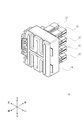
- FIG. 1 is an external perspective view of a connector according to an embodiment of the present invention.
- the front, rear, up, down, left and right directions are specified.
- the side mated with the mating connector is the front side.
- a connector 10 includes a plurality of cavities 12 in which terminal fittings connected to electric wire terminals are accommodated, and a connector main body 14.
- the plurality of cavities 12 are configured in a cylindrical shape as separate members independent of the connector main body 14.
- the plurality of cavities 12 are also configured as separate members independent of each other.
- the connector body 14 is a holder that accommodates the plurality of cavities 12 (hereinafter, the connector body 14 may be expressed as the holder 14).
- FIG. 1 is a left side view of the holder 14.
- FIG. 3 is a left side view of the cavity 12
- FIG. 4 is a front view of the cavity 12.
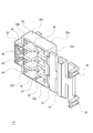
- 5 to 9 are drawings showing the holder 14 (connector body 14).
- 5 is an external perspective view of the holder 14
- FIG. 6 is an external perspective view showing the holder 14 in a state where the inside can be seen
- FIG. 7 is a rear view of the holder 14
- FIG. 8 is a front view of the holder 14.
- FIG. 9 is a left side view of the holder 14.
- the cavity 12 is formed in a rectangular tube shape so that a terminal fitting (not shown) can be accommodated therein.
- the terminal fitting is locked inside the cavity 12 by being locked to a locking projection (not shown) inside the cavity 12.
- the opening side 12a behind the cavity 12 is a side into which a terminal fitting (cylindrical terminal 70 described later) is inserted, and the opening side 12b before the cavity 12 is a terminal fitting (pin terminal 62) of a mating connector 60 described later. Is the side to be inserted.
- Both the rear opening side 12a and the front opening side 12b of the cavity 12 are formed with a taper that widens the entrance so that a terminal fitting (a cylindrical terminal 70 and a pin terminal 62 described later) can be easily inserted.
- a pair of protrusions 22a and 22b extending the entire length of the cavity 12 in the front-rear direction is formed on one side of the cavity 12 (right side in FIG. 2). Further, on the other side of the cavity 12 (left side in FIG. 2), a pair of protrusions 24 a and 24 b extending only to a part of the rear side of the cavity 12 are formed.
- the groove between the pair of protrusions 22a and 22b on one side and the groove between the pair of protrusions 24a and 24b on the other side serves as a guide, so that the cavity 12 can be easily inserted into the holder 14.
- a lance locking hole 26 is formed as a recessed portion that is depressed by one step, and a lance 44 of the holder 14 described later enters and the lance 44 is engaged. It has come to be stopped.
- a protrusion-like stopper 28 that protrudes further in the right direction is formed at the rear end of the upper protrusion 22a of the pair of protrusions 22a, 22b on one side. 38.
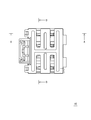
- the holder 14 includes a box-shaped holder main body 30 surrounded by a front surface 30a, both side surfaces 30b and 30c, and upper and lower surfaces 30d and 30e, and an open rear side 30f.
- a cover 32 that covers the rear side 30f that is opened, and a lock 34 that is engaged with the mating connector when the holder 14 is fitted to the mating connector.
- the inside of the holder body 30 is a storage chamber that stores a portion of the cavity 12 that is not fitted to the mating connector.
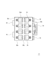
- the front surface 30 a of the holder body 30 has a plurality of insertion holes 36 into which the individual cavities 12 are inserted so that a portion of the cavity 12 to be received that fits into the mating connector protrudes from the holder body 30. Is formed through. In the configuration shown in FIGS. 5 to 9, two insertion holes 36 are arranged in the left-right direction, and four insertion holes 36 are arranged in the up-down direction.
- an abutting protrusion 38 on which the stopper 28 of the cavity 12 abuts projects inside the front surface 30 a of the holder body 30, and It is formed so as to be continuous along the vertical direction.
- the contact protrusions 38 also serve as ribs that reinforce the front surface 30a of the holder main body 30, and are connected to the upper and lower ribs 40 and 42 that reinforce the upper and lower surfaces 30d and 30e of the holder main body 30 in the same manner. .
- lances 44 Inside the both side surfaces 30b and 30c of the holder body 30, there are provided lances 44 that enter and are locked into the lance locking holes 26 of the cavity 12 when the cavity 12 is inserted.
- an engaging claw 46 that engages with an engaging piece 50 of the cover 32 described later is provided.
- the cover 32 is connected to the right rear end of the holder body 30 by two hinges 48 provided at the right end.
- the cover 32 can be rotated with the hinge 48 as a rotation center, and the opening of the rear side 30f of the holder body 30 can be opened and closed by the rotation of the cover 32.
- Engaging pieces 50 that engage with engaging claws 46 formed on the outer side of the left side surface 30 b of the holder body 30 are provided at two positions above and below the left end of the cover 32.
- a protrusion 52 extending in the vertical direction is formed at the central portion of the inner surface of the cover 32.
- the cover 32 covers the rear side 30f of the holder body 30, it is inserted into the insertion hole 36 of the holder 14. It faces the rear end face of the protruding stopper 28 formed at the rear end of the cavity 12 at a predetermined interval (clearance).
- a through hole 54 through which an electric wire connected to a terminal fitting accommodated in the cavity 12 passes is formed on both sides of the portion where the protrusion 52 is formed.
- the through hole 54 faces the opening side 12 a behind the cavity 12, and the terminal fitting to which the wire terminal is connected is accommodated in the cavity 12 through the through hole 54.
- the electric wire connected to the terminal fitting housed inside the cavity 12 is drawn out of the connector 10 through the through hole 54.
- a guide groove 56 extending in the upward direction or the downward direction is connected to the through hole 54, and the guide direction of the electric wire from the through hole 54 is restricted upward or downward by the guide groove 56. Can do.
- the lock 34 is formed integrally with the holder body 30 on the outside of the left side surface 30b of the holder body 30 so that the fitting state can be maintained when the connector 10 is fitted with the mating connector.
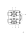
- FIG. 10 shows a state in which the cavity 12 is inserted into a part of the insertion hole 36 of the holder 14 having such a configuration.
- the cavity 12 to be inserted into the left insertion hole 36 has a pair of protrusions 22a and 22b on one side arranged on the right side and a pair of protrusions 24a and 24b on the other side arranged on the left side.
- a pair of protrusions 22a and 22b on one side are arranged on the left side
- a pair of protrusions 24a and 24b on the other side are arranged on the right side.
- the protruding stopper 28 of the cavity 12 inserted into the left insertion hole 36 is disposed on the upper side, and the protruding stopper 28 of the cavity 12 inserted into the right insertion hole 36 is disposed on the lower side. . Since these stoppers 28 are arranged in pairs so as to overlap in the vertical direction, the size of the connector 10 in the left-right direction can be reduced.
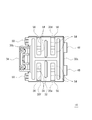
- 11 to 14 are views showing the connector 10 as a completed form in which the cavity 12 is inserted into the insertion hole 36 of the holder 14.
- 11 is a rear view of the connector 10
- FIG. 12 is a cross-sectional view taken along the line AA of the connector 10 in FIG. 11
- FIG. 13 is a cross-sectional view taken along the line BB of the connector 10 in FIG. 2 is a front view of the connector 10.
- FIG. 12 is a cross-sectional view taken along the line AA of the connector 10 in FIG. 11
- the cavity 12 inserted into the insertion hole 36 of the holder 14 is locked to the holder 14 by the lance 44 of the holder 14 entering the lance locking hole 26 of the cavity 12.
- the pair of protrusions 24 a and 24 b on the other side having the lance locking holes 26 of the cavity 12 are brought into contact with the front surface 30 a of the holder body 30, and the stopper 28 of the cavity 12 is brought into contact with the holder 14. It abuts on the strip 38.
- a clearance L is provided between the side surface 12 c having the lance locking hole 26 of the cavity 12 and the insertion hole 36 of the holder 14.
- a clearance L is provided between the pair of protrusions 22 a, 22 b on one side having the stopper 28 of the cavity 12 and the protrusion protrusion 38 for the holder 14.
- a clearance L is provided between the stopper 28 of the cavity 12 and the protrusion 52 on the inner surface of the cover 32.
- FIG. 15 is a schematic diagram showing a state before the connector 10 and the mating connector 62 are fitted together.
- FIG. 16 is a schematic view showing a state in which the connector 10 and the mating connector 62 are fitted and cut along the front-rear direction at the center position of the cavity 12.
- the electrical / electronic device (member) 60 such as a substrate that is collectively connected by the connector 10 of the present invention includes a mating connector 62 at one edge.
- the mating connector 62 includes a pin terminal 64 drawn from one end edge and a hood portion 66 that covers the pin terminal 64.
- two pin terminals 64 are drawn from one end edge.
- the two hood portions 66 that individually cover the two pin terminals 64 are connected to each other by integral molding.
- the hood portion 66 is formed in a rectangular tube shape in cross section, is open at the front side to which the connector 10 of the present invention is fitted, and has a length covering the periphery of the pin terminal 64.
- the electric / electronic devices (members) 60 having such a configuration gather, and the plurality of electric / electronic devices (members) 60 are stacked in the vertical direction.
- the mating connectors 62 of the plurality of electric / electronic devices (members) 60 are arranged in a vertical direction and are grouped together by arranging the plurality of electric / electronic devices (members) 60 in a stacked manner.
- the left side of the two hood portions 66 of the electric / electronic device (member) 60 located at the lowermost layer is directed upward to the left side of the two hood portions 66 of the electric / electronic device (member) 60 located at the uppermost layer.
- a plate-shaped guide member 68 extending in the direction is provided, and the left side of the two hood portions 66 of each electric / electronic device (member) 60 is in contact with the guide member 68 and positioned.
- the mating connectors 62 of the plurality of electric / electronic devices (members) 60 are arranged in the vertical direction and grouped together.
- a lock locking claw (not shown) that locks the lock 34 of the connector 10 is provided on the left outer surface of the guide member 68.
- all the cavities 12 of the plurality of cavities 12 are allowed to move with respect to the holder 14, but one or more of the plurality of cavities 12 It is also possible to adopt a configuration in which the movement of the cavity is restricted with respect to the holder. Since the movement of such a cavity is restricted with respect to the holder, it can be used as a reference cavity for positioning when the connector of the present invention is fitted to the mating connector. As a result, the connector can be easily fitted into the mating connector.
- the form in which the movement of the cavity is restricted, 1) the form in which the cavity is integrally formed with the holder, 2) the form in which the cavity is press-fitted into the insertion hole of the holder body, and 3) the cavity is integrally formed with the cover. 2) a form in which the cavity is pressed against the cover, and the like.
- a cavity shaped like this can be used as a reference cavity.
- the cavities 12 are arranged in two rows in the left-right direction.
- the cavities 12 may be arranged in one row in the left-right direction, or three or more rows are arranged in parallel. It may be a configuration.
- the cover 32 is provided, the structure in which the cover 32 is not provided may be sufficient.
- the cavity 12 is a rectangular tube shape, other forms, such as a cylindrical shape, may be sufficient.
- the guide groove 56 formed in the cover 32 penetrates both surfaces of the cover 32 as in the case of the through hole 54, but does not penetrate both surfaces of the cover 32, and the outer surface of the cover 32. It can also be formed like a recessed portion with a recess.
Landscapes
- Connector Housings Or Holding Contact Members (AREA)
- Details Of Connecting Devices For Male And Female Coupling (AREA)
Abstract
La présente invention concerne un connecteur qui, même lorsque des tolérances se produisent en raison de la stratification sur un côté d'un dispositif (élément) électrique/électronique qui a été stratifié, peut établir des connexions toutes en même temps avec des connecteurs du côté correspondant de ces dispositifs (éléments). Le connecteur possède une pluralité de cavités (12) qui accueillent une borne. Les cavités (12) ont une forme cylindrique en tant qu'éléments séparés indépendants d'un corps principal de connecteur (14), et cette pluralité de cavités (12) est constituée comme des éléments séparés indépendants les uns des autres. Le corps principal de connecteur (14) forme un support qui accueille cette pluralité de cavités (12). Cette pluralité de cavités (12) est verrouillée sur le corps principal de connecteur (14) de façon individuelle. Dans cette partie de verrouillage, un débattement est formé entre les cavités individuelles (12) et le corps principal de connecteur (14). Du fait de ce débattement, le mouvement des cavités (12) est accueilli par le corps principal de connecteur (14).
Priority Applications (3)
| Application Number | Priority Date | Filing Date | Title |
|---|---|---|---|
| CN201280018784.XA CN103493308B (zh) | 2011-04-18 | 2012-04-09 | 连接器 |
| EP12774520.6A EP2701241B1 (fr) | 2011-04-18 | 2012-04-09 | Connecteur |
| US14/009,393 US9379473B2 (en) | 2011-04-18 | 2012-04-09 | Connector |
Applications Claiming Priority (2)
| Application Number | Priority Date | Filing Date | Title |
|---|---|---|---|
| JP2011091639A JP5673320B2 (ja) | 2011-04-18 | 2011-04-18 | コネクタ |
| JP2011-091639 | 2011-04-18 |
Publications (1)
| Publication Number | Publication Date |
|---|---|
| WO2012144364A1 true WO2012144364A1 (fr) | 2012-10-26 |
Family
ID=47041476
Family Applications (1)
| Application Number | Title | Priority Date | Filing Date |
|---|---|---|---|
| PCT/JP2012/059659 Ceased WO2012144364A1 (fr) | 2011-04-18 | 2012-04-09 | Connecteur |
Country Status (5)
| Country | Link |
|---|---|
| US (1) | US9379473B2 (fr) |
| EP (1) | EP2701241B1 (fr) |
| JP (1) | JP5673320B2 (fr) |
| CN (1) | CN103493308B (fr) |
| WO (1) | WO2012144364A1 (fr) |
Cited By (2)
| Publication number | Priority date | Publication date | Assignee | Title |
|---|---|---|---|---|
| CN105103384A (zh) * | 2013-04-05 | 2015-11-25 | 株式会社自动网络技术研究所 | 连接器 |
| CN105103382A (zh) * | 2013-04-05 | 2015-11-25 | 株式会社自动网络技术研究所 | 连接器 |
Families Citing this family (10)
| Publication number | Priority date | Publication date | Assignee | Title |
|---|---|---|---|---|
| JP5907390B2 (ja) * | 2013-04-05 | 2016-04-26 | 株式会社オートネットワーク技術研究所 | コネクタ |
| JP2014203694A (ja) * | 2013-04-05 | 2014-10-27 | 株式会社オートネットワーク技術研究所 | コネクタ |
| JP2014203691A (ja) * | 2013-04-05 | 2014-10-27 | 株式会社オートネットワーク技術研究所 | コネクタ |
| JP6044495B2 (ja) * | 2013-09-10 | 2016-12-14 | 株式会社オートネットワーク技術研究所 | 配線モジュール |
| JP6179475B2 (ja) | 2014-07-30 | 2017-08-16 | 株式会社オートネットワーク技術研究所 | コネクタユニット |
| JP6591363B2 (ja) * | 2016-07-21 | 2019-10-16 | 日本航空電子工業株式会社 | コネクタ |
| DE102018203628A1 (de) * | 2018-03-09 | 2019-09-12 | Te Connectivity Germany Gmbh | Elektrischer Stecker mit elastischen Anpresselementen |
| JP7093699B2 (ja) * | 2018-08-27 | 2022-06-30 | イリソ電子工業株式会社 | 電気コネクタ |
| US11837808B2 (en) * | 2018-12-28 | 2023-12-05 | Autonetworks Technologies, Ltd. | Board connector and device |
| JP7449819B2 (ja) * | 2020-08-25 | 2024-03-14 | 古河電気工業株式会社 | コネクタホルダおよび該コネクタホルダを備えたワイヤハーネス |
Citations (5)
| Publication number | Priority date | Publication date | Assignee | Title |
|---|---|---|---|---|
| JPH11299054A (ja) | 1998-04-07 | 1999-10-29 | Yazaki Corp | 電気接続箱及び該電気接続箱におけるコネクタ部の形成方法 |
| JP2001237028A (ja) * | 2000-02-24 | 2001-08-31 | Keihin Corp | コネクタ |
| JP2007242251A (ja) * | 2006-03-03 | 2007-09-20 | Jst Mfg Co Ltd | 電気コネクタ |
| JP2008198429A (ja) * | 2007-02-09 | 2008-08-28 | Japan Aviation Electronics Industry Ltd | コネクタ及びコネクタ装置 |
| JP2008293810A (ja) * | 2007-05-25 | 2008-12-04 | Sumitomo Wiring Syst Ltd | コネクタ |
Family Cites Families (10)
| Publication number | Priority date | Publication date | Assignee | Title |
|---|---|---|---|---|
| JP2896783B2 (ja) * | 1989-03-01 | 1999-05-31 | 日本航空電子工業株式会社 | コネクタハウジングの二重ロック構造 |
| US5184961A (en) * | 1991-06-20 | 1993-02-09 | Burndy Corporation | Modular connector frame |
| JP3047053B2 (ja) * | 1991-12-27 | 2000-05-29 | 住友電装株式会社 | 自動車用ワイヤハーネスに用いる組み合わせコネクタ |
| ES2136392T3 (es) * | 1995-04-12 | 1999-11-16 | Whitaker Corp | Unidad modular de conexion electrica. |
| CN1187699A (zh) * | 1996-04-24 | 1998-07-15 | 住友电装株式会社 | 连接器 |
| JP3120730B2 (ja) | 1996-05-21 | 2000-12-25 | 住友電装株式会社 | コネクタ |
| US6095852A (en) * | 1998-12-17 | 2000-08-01 | Yazaki North America, Inc. | Connector bracket wire shield with connector retention arms |
| JP3266198B2 (ja) * | 1999-10-25 | 2002-03-18 | オムロン株式会社 | センサシステム |
| US7118414B2 (en) * | 2004-01-22 | 2006-10-10 | Northstar Systems, Inc. | Computer input/output connector assembly |
| JP4591228B2 (ja) * | 2005-06-21 | 2010-12-01 | 住友電装株式会社 | コネクタ |
-
2011
- 2011-04-18 JP JP2011091639A patent/JP5673320B2/ja not_active Expired - Fee Related
-
2012
- 2012-04-09 CN CN201280018784.XA patent/CN103493308B/zh not_active Expired - Fee Related
- 2012-04-09 US US14/009,393 patent/US9379473B2/en not_active Expired - Fee Related
- 2012-04-09 WO PCT/JP2012/059659 patent/WO2012144364A1/fr not_active Ceased
- 2012-04-09 EP EP12774520.6A patent/EP2701241B1/fr not_active Not-in-force
Patent Citations (5)
| Publication number | Priority date | Publication date | Assignee | Title |
|---|---|---|---|---|
| JPH11299054A (ja) | 1998-04-07 | 1999-10-29 | Yazaki Corp | 電気接続箱及び該電気接続箱におけるコネクタ部の形成方法 |
| JP2001237028A (ja) * | 2000-02-24 | 2001-08-31 | Keihin Corp | コネクタ |
| JP2007242251A (ja) * | 2006-03-03 | 2007-09-20 | Jst Mfg Co Ltd | 電気コネクタ |
| JP2008198429A (ja) * | 2007-02-09 | 2008-08-28 | Japan Aviation Electronics Industry Ltd | コネクタ及びコネクタ装置 |
| JP2008293810A (ja) * | 2007-05-25 | 2008-12-04 | Sumitomo Wiring Syst Ltd | コネクタ |
Cited By (6)
| Publication number | Priority date | Publication date | Assignee | Title |
|---|---|---|---|---|
| CN105103384A (zh) * | 2013-04-05 | 2015-11-25 | 株式会社自动网络技术研究所 | 连接器 |
| CN105103382A (zh) * | 2013-04-05 | 2015-11-25 | 株式会社自动网络技术研究所 | 连接器 |
| EP2983251A4 (fr) * | 2013-04-05 | 2016-03-09 | Autonetworks Technologies Ltd | Connecteur |
| EP2983250A4 (fr) * | 2013-04-05 | 2016-03-09 | Autonetworks Technologies Ltd | Connecteur |
| US9413095B2 (en) | 2013-04-05 | 2016-08-09 | Autonetworks Technologies, Ltd. | Connector |
| CN105103384B (zh) * | 2013-04-05 | 2017-10-31 | 株式会社自动网络技术研究所 | 连接器 |
Also Published As
| Publication number | Publication date |
|---|---|
| US9379473B2 (en) | 2016-06-28 |
| CN103493308A (zh) | 2014-01-01 |
| US20140024262A1 (en) | 2014-01-23 |
| CN103493308B (zh) | 2016-10-05 |
| EP2701241B1 (fr) | 2017-09-27 |
| EP2701241A4 (fr) | 2015-01-07 |
| JP5673320B2 (ja) | 2015-02-18 |
| JP2012226882A (ja) | 2012-11-15 |
| EP2701241A1 (fr) | 2014-02-26 |
Similar Documents
| Publication | Publication Date | Title |
|---|---|---|
| JP5673320B2 (ja) | コネクタ | |
| CN103378490B (zh) | 电连接器组合 | |
| US8936474B2 (en) | Electrical junction box | |
| JP5808504B2 (ja) | 電気的なカップリングエレメント | |
| KR101632557B1 (ko) | 레버 타입 커넥터 | |
| WO2009148027A1 (fr) | Connecteur électrique | |
| CN102265464B (zh) | 电连接器 | |
| JP2019016575A (ja) | コネクタ | |
| WO2014162891A1 (fr) | Connecteur | |
| JP2009048861A (ja) | 電気コネクタ | |
| CN105703125A (zh) | 电连接器 | |
| JP5768925B2 (ja) | コネクタ | |
| JP5692598B2 (ja) | 嵌合検知構造 | |
| JP5871709B2 (ja) | 電気コネクタ及びその製造方法 | |
| WO2014162889A1 (fr) | Connecteur | |
| JP6015628B2 (ja) | コネクタ | |
| US9627794B2 (en) | Connector element having a contact module engagement | |
| WO2017047567A1 (fr) | Structure de sécurité de connecteur et couvercle de protection | |
| JP2018018793A (ja) | コネクタ装置 | |
| JP2005044586A (ja) | 電気接続用プラグ | |
| JP6248062B2 (ja) | コネクタ | |
| JP5626104B2 (ja) | 電気接続箱 | |
| JP2010118150A (ja) | コネクタ | |
| KR101821107B1 (ko) | 스위치 어셈블리 및 이를 포함하는 차량용 도어 | |
| JP4151535B2 (ja) | 露出形モジュラジャック |
Legal Events
| Date | Code | Title | Description |
|---|---|---|---|
| 121 | Ep: the epo has been informed by wipo that ep was designated in this application |
Ref document number: 12774520 Country of ref document: EP Kind code of ref document: A1 |
|
| REEP | Request for entry into the european phase |
Ref document number: 2012774520 Country of ref document: EP |
|
| WWE | Wipo information: entry into national phase |
Ref document number: 2012774520 Country of ref document: EP |
|
| WWE | Wipo information: entry into national phase |
Ref document number: 14009393 Country of ref document: US |
|
| NENP | Non-entry into the national phase |
Ref country code: DE |