WO2012144459A1 - 更生タイヤの製造方法及び当該製造方法に適したタイヤ - Google Patents
更生タイヤの製造方法及び当該製造方法に適したタイヤ Download PDFInfo
- Publication number
- WO2012144459A1 WO2012144459A1 PCT/JP2012/060268 JP2012060268W WO2012144459A1 WO 2012144459 A1 WO2012144459 A1 WO 2012144459A1 JP 2012060268 W JP2012060268 W JP 2012060268W WO 2012144459 A1 WO2012144459 A1 WO 2012144459A1
- Authority
- WO
- WIPO (PCT)
- Prior art keywords
- tire
- tread
- belt
- application surface
- manufacturing
- Prior art date
- Legal status (The legal status is an assumption and is not a legal conclusion. Google has not performed a legal analysis and makes no representation as to the accuracy of the status listed.)
- Ceased
Links
Images

Classifications
-
- B—PERFORMING OPERATIONS; TRANSPORTING
- B29—WORKING OF PLASTICS; WORKING OF SUBSTANCES IN A PLASTIC STATE IN GENERAL
- B29D—PRODUCING PARTICULAR ARTICLES FROM PLASTICS OR FROM SUBSTANCES IN A PLASTIC STATE
- B29D30/00—Producing pneumatic or solid tyres or parts thereof
- B29D30/06—Pneumatic tyres or parts thereof (e.g. produced by casting, moulding, compression moulding, injection moulding, centrifugal casting)
- B29D30/52—Unvulcanised treads, e.g. on used tyres; Retreading
- B29D30/54—Retreading
-
- B—PERFORMING OPERATIONS; TRANSPORTING
- B60—VEHICLES IN GENERAL
- B60C—VEHICLE TYRES; TYRE INFLATION; TYRE CHANGING; CONNECTING VALVES TO INFLATABLE ELASTIC BODIES IN GENERAL; DEVICES OR ARRANGEMENTS RELATED TO TYRES
- B60C11/00—Tyre tread bands; Tread patterns; Anti-skid inserts
- B60C11/02—Replaceable treads
-
- B—PERFORMING OPERATIONS; TRANSPORTING
- B29—WORKING OF PLASTICS; WORKING OF SUBSTANCES IN A PLASTIC STATE IN GENERAL
- B29D—PRODUCING PARTICULAR ARTICLES FROM PLASTICS OR FROM SUBSTANCES IN A PLASTIC STATE
- B29D30/00—Producing pneumatic or solid tyres or parts thereof
- B29D30/06—Pneumatic tyres or parts thereof (e.g. produced by casting, moulding, compression moulding, injection moulding, centrifugal casting)
- B29D30/52—Unvulcanised treads, e.g. on used tyres; Retreading
- B29D30/54—Retreading
- B29D2030/541—Abrading the tyre, e.g. buffing, to remove tread and/or sidewalls rubber, to prepare it for retreading
-
- Y—GENERAL TAGGING OF NEW TECHNOLOGICAL DEVELOPMENTS; GENERAL TAGGING OF CROSS-SECTIONAL TECHNOLOGIES SPANNING OVER SEVERAL SECTIONS OF THE IPC; TECHNICAL SUBJECTS COVERED BY FORMER USPC CROSS-REFERENCE ART COLLECTIONS [XRACs] AND DIGESTS
- Y10—TECHNICAL SUBJECTS COVERED BY FORMER USPC
- Y10T—TECHNICAL SUBJECTS COVERED BY FORMER US CLASSIFICATION
- Y10T152/00—Resilient tires and wheels
- Y10T152/10—Tires, resilient
- Y10T152/10495—Pneumatic tire or inner tube
- Y10T152/10765—Characterized by belt or breaker structure
Definitions
- the present invention relates to a method for manufacturing a corrected tire, and more particularly to a method for manufacturing a corrected tire capable of improving durability and a tire suitable for the manufacturing method.
- a buff that cuts the outer peripheral surface of the tire is used.
- a method to obtain a renewed tire as a final product in which the base tire and the new tread rubber are integrated by performing the hanging work, winding the tread rubber around the buff surface after buffing, and putting it in the vulcanizer are known.
- a cushion rubber composed of a lower rubber layer and an upper rubber layer is disposed between a belt and a crown protective layer, and the stress when an elongation of 300% or more of the upper rubber layer is applied is given.
- the upper rubber layer is lower than the stress when the lower rubber layer is stretched by 300% or more and the breaking elongation of the upper rubber layer is larger than the breaking elongation of the lower rubber layer.
- a rehabilitated tire for aircraft has been proposed in which the interface between the rubber layer and the lower rubber layer is easily peeled off and the cushion rubber is prevented from being peeled off together with the tread rubber and the crown protective layer.
- the present invention prevents a buff surface from being always formed at the same position by cutting performed at the time of tire retreading, thereby reducing the peel resistance with a new tread rubber.
- a method for manufacturing a retread tire including a step of cutting a tread rubber of a tire along a circumferential direction and forming a tread application surface capable of attaching a new tread rubber.
- the position where the tread application surface is formed is changed in the radial direction of the tire in accordance with an increase in the number of tire regenerations.
- the tread since the position of the tread application surface where the new tread rubber is applied is changed in the radial direction of the tire in accordance with an increase in the number of tire regenerations, the tread is repositioned at the same position every time by a plurality of regeneration operations. It is possible to prevent the sticking surface from being formed.
- a retreaded tire maintaining durability equivalent to a so-called new tire can be obtained without deteriorating the peel resistance from the tread rubber even after a plurality of retreading operations.
- the position where the tread application surface is formed is changed from the radially outer side to the inner side of the tire, so the tread application surface formed in the past by one rehabilitation operation.
- At least one of the rehabilitations of a plurality of times is configured such that the position where the tread application surface is formed is radially outer than the restraining member positioned radially outermost in the tire. .
- the position where the tread application surface is formed is radially outward from the restraining member located at the outermost radial direction in the tire. Can be prevented, and the restraining member can be used a plurality of times.
- the tire includes a belt layer, and the belt located at the outermost radial direction in the belt layer has a deepest groove bottom formed in the tread portion when the inner pressure is filled. It was set as the structure located in a radial inside rather than the virtual line which passes a part.
- the outermost belt in the radial direction is formed in the tread portion because it is located radially inward from the imaginary line passing through the deepest portion of the groove bottom formed in the tread portion when the inner pressure is filled.
- the tire according to the above configuration has a belt reinforcing body disposed radially outward from the belt layer, and the belt reinforcing body passes through the deepest portion of the groove bottom formed in the tread portion when filling with internal pressure. It was set as the structure located in a radial inside rather than an imaginary line. According to the present invention, the belt reinforcing body located at the outermost radial direction is located on the inner side in the radial direction from the imaginary line passing through the deepest part of the groove bottom formed in the tread portion when the inner pressure is filled. It is possible to reliably prevent the surface of the belt reinforcing body from being exposed or causing trauma when removing the grooves formed in.
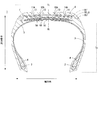
- FIG. 1 is a cross-sectional view of the tire 1 in the width direction.
- the basic structure of the tire 1 will be described with reference to FIG.
- a tire 1 is an undetermined tire and is roughly a pair of bead cores 2, a carcass 3, a bead filler 4, a belt layer 5, a belt reinforcing body 6, a tread rubber layer 7 (hereinafter simply referred to as a tread rubber 7).
- the bead core 2 is an aggregate of steel cords formed in an annular shape, and is a pair of members provided to be separated in the width direction of the tire 1.
- the bead filler 4 is a hard rubber positioned radially outward from the bead core 2 and is inserted so as to be sandwiched between ends of the carcass 3 folded around the bead core 2.
- the bead filler 4 is not necessarily inserted, and the presence or absence thereof is appropriately selected according to the required performance of the tire 1.
- the belt layer 5 is a region located radially outside the carcass 3 in the tread portion Tt of the tire 1 and is formed by laminating a plurality of belts 5A to 5C in the radial direction. Further, the plurality of belts 5A to 5C are integrated by an adhesive layer or a rubber layer interposed therebetween, and the belt layer 5 is a tag that suppresses protrusion of the tread portion Tt in the radial direction when the tire rotates. It is a restraining member that exhibits the effect.
- the tread rubber layer 7 is a region disposed radially outward from the belt layer 5, and has a plurality of tread grooves 11 to 11 extending continuously along the circumferential direction on the surface that contacts the road surface during rotation.
- a predetermined tread pattern including 14 is formed.
- the tread pattern is not limited to the example shown in the drawings, and is a rib groove type, a lug groove type, a block type in which a rib groove and a lug groove are combined, a sipe that increases edge components, and the like.
- channel was formed is also included.
- a belt reinforcing body 6 for reinforcing the belt layer 5 is disposed in the tread rubber layer 7 in this example.
- the belt reinforcing body 6 is a member in which, for example, steel cords and Kevlar cords extending in the width direction of the tire 1 are gathered in a wave shape like the belt layer 5.
- the belt reinforcing body 6 is disposed so as to be spaced outward in the radial direction from the belt 5 ⁇ / b> A positioned at the outermost radial direction constituting the belt layer 5, and is positioned inside the tread rubber layer 7.
- the belt reinforcing body 6 is a restraining member that exhibits a tagging effect in the same manner as the belt layer 5 and a member that prevents the belt layer 5 from being damaged. Further, in this example, the belt reinforcing body 6 is a restraining member located on the outermost side in the radial direction of the tire 1.
- region where the belt layer 5 and the tread rubber layer 7 exist in the tire 1 of FIG. 1 is called the tread part Tt for convenience of explanation
- a region having the bead core 2 and the bead filler 4 and radially inward of the tread portion Tt is referred to as a side portion Ts.
- the center position in the width direction of the tire 1 is defined as the center CL in the width direction.
- region changes with the uses, classification, size, etc. of a tire, for example, it can also be grasped
- the number of rehabilitations is described as three, but the present invention is not limited to this.
- imaginary lines (buff lines) B1, B2, B3 in FIG. 1 the tread rubber layer 7 in the tread portion Tt of the tire 1 is buffed outside the figure from the outside in the radial direction toward the inside as the number of rehabilitation increases. It is cut (buffed) by the device. That is, every time buffing is completed, the tread application surface B is formed at the position indicated by each virtual line (B1, B2, B3), and the position of the tread application surface B is changed from the radially outer side to the inner side. Will be changed towards.
- the tread rubber layer 7 is cut by pressing the surface of the tread rubber layer 7 against the cutting mechanism of the buffing device while rotating the tire 1 that is rotatably fixed at a predetermined speed.
- the buffing device operates so as to form a predetermined tread application surface B at a position indicated by each virtual line according to the number of rehabilitations. Then, the tread pasting surface B from which the tread grooves 11 to 14 are removed is uniformly formed along the circumferential direction in the tread portion Tt after completion of buffing.
- the tire in a state where the tread grooves 11 to 14 are removed and the tread pasting surface B is formed is a tire that becomes a base of a newly manufactured retread tire, and is referred to as a base tire. Further, the tread pasting surface B is a roughened state in which an unvulcanized tread rubber described later is easily fixed.
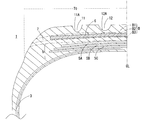
- FIG. 2 is an enlarged cross-sectional view of the tire showing the position where the tread application surface B is formed by three rehabilitations.
- the position of the tread pasting surface B formed according to the number of rehabilitations will be described.
- the tread application surface B1 formed by the first rehabilitation is radially inward from the groove bottoms 11A to 14A of the tread grooves 11 to 14 formed on the surface of the tread rubber 7, And it forms in the range of the radial outside rather than the belt reinforcement body 6 arrange
- the tread pasting surface B1 formed by the first rehabilitation By setting the tread pasting surface B1 formed by the first rehabilitation to the inside in the radial direction from the groove bottoms 11A to 14A of the tread grooves 11 to 14, the tread grooves 11 to 14 whose depth has been polished down by abrasion with the road surface. Can be reliably removed. Moreover, since the tread sticking surface B1 is radially outer than the belt reinforcement body 6 disposed in the tread rubber layer 7, the belt reinforcement body 6 can be reused without newly disposed, which is economical. Is advantageous.
- the tread rubber layer 7 may be cut until the outer surface in the radial direction of the belt reinforcement 6 is exposed. However, in consideration of the case where the belt reinforcement 6 is damaged due to buffing, the tread rubber layer 7 is formed on the belt reinforcement 6. It is preferable to keep the tread rubber layer 7 until it remains slightly.
- the base tire on which the tread pasting surface B is formed is conveyed to a tread rubber pasting step and a vulcanizing step, which will be described later, and an unvulcanized tire corresponding to the cut thickness.
- a new tread rubber 7 is wound and vulcanized to complete the manufacture of a retread tire that can exhibit the same performance as the tire 1 before the correction.
- the tread pasting surface B2 formed by the second rehabilitation will be described.
- the tread application surface B1 is set in the above range and the wear of the corrected tire progresses and the tread rubber layer 7 is cut again to regenerate the tire
- the tread application surface B2 is formed by the first regeneration. It changes to the inner side in the radial direction from the tread application surface B1. More specifically, the tread application surface B ⁇ b> 2 is radially inward of the belt reinforcing body 6 as a restraining member positioned at the outermost radial direction and is radially outward of the belt layer 5. It is formed within the range.
- the tread application surface B2 formed by the second regeneration is radially inward of the tread application surface B1 formed by the first regeneration, that is, the position where the tread application surface B is formed is set to a different position.
- the tread application surface B2 is also cut at the same time.
- a plurality of tread pasting surfaces (B1, B2) do not exist in the retread tire after completion of manufacture, and the durability of the retread tire as a whole is not lowered. That is, from the viewpoint of preventing a decrease in peel resistance, the tread application surface B2 may be formed radially outward from the tread application surface B1, but there are a plurality of tread application surfaces B in the tire. In order to avoid this, it is preferable that the tread application surface B2 is formed by changing the tread application surface B1 radially inward from the tread application surface B1.
- the belt reinforcing body 6 is also removed simultaneously by cutting the tread rubber layer 7 by the second rehabilitation, but the belt reinforcing body 6 is subjected to a tread rubber attaching process and a vulcanizing process described later. It will be arranged again.
- the tread pasting surface B3 formed by the third rehabilitation will be described.
- the tread application surface B2 is set in the above range and the wear of the corrected tire proceeds and the tread rubber layer 7 is cut again to regenerate the tire
- the tread application surface B3 is formed by the second regeneration. It changes to the inner side in the radial direction from the tread application surface B2. More specifically, the tread application surface B3 is formed in the range of the tread rubber layer 7 that is radially inward of the tread application surface B2 and radially outward of the belt layer 5.
- the tread application surface B3 formed by the third rehabilitation is radially inward of the tread application surface B2 formed by the second renewal, that is, the position where the tread application surface B is formed.
- the peeling resistance is not lowered due to vulcanization deterioration as compared with the case where the tread application surface B is formed at the same position every time.
- the tread application surface B on which the new tread rubber 7 is applied is directed in the radial direction, more preferably in the radial direction as the number of rehabilitation increases.
- the cutting range at the tread portion Tt is set within the range of the tread rubber layer 7, but the present invention is not limited to this, and the cutting range can be extended to the belt layer 5.
- the tread portion Tt is cut until the surface of the belt 5A located in the outermost radial direction constituting the belt layer 5 is exposed, or the range is further expanded to increase the radial outermost position. It can be considered that the belt 5A located outside is removed by cutting and a tread rubber layer 7 including a new belt 5A is attached. Further, the position and the number of formations of the tread application surface B that increases in accordance with the number of rehabilitations can be appropriately changed as long as the durability as a base tire after cutting does not hinder. That is, the tread application surface B may be formed two or more times on the radially outer side of the belt reinforcing body 6, or the tread application surface B may be formed four or more times by narrowing the cutting interval.
- the said process includes the tread rubber sticking process which winds the unvulcanized new tread rubber 7 around a base tire, and the vulcanization process which couple
- a ribbon-like unvulcanized tread rubber 7 formed with a width shorter than the width of the tread application surface B is provided on the tread application surface B (B1, B2, B3) formed by cutting the tread portion Tt. It is wound a predetermined number of times so as to have a preset thickness along the circumferential direction of the base tire.
- the amount (thickness) of the tread rubber 7 that is cut from the first time to the third time gradually increases. Therefore, in order to supplement the amount of the tread rubber 7 that has been cut, The thickness of the rubber 7 is set to increase as the number of rehabilitation increases. Further, since the belt reinforcement body 6 is removed in the second and subsequent rehabilitations, a new belt reinforcement body 6 is disposed in the new tread rubber 7 wound by the second and subsequent rehabilitations.
- the base tire and the tread rubber 7 that are preliminarily integrated in the tread rubber attaching step are conveyed to the vulcanization step.
- the vulcanization step the pre-integrated base tire and the unvulcanized tread rubber 7 are put into a mold and then vulcanized in a heated and pressurized state. After a predetermined time, the cross-linking reaction of the unvulcanized tread rubber 7 proceeds, the tread rubber 7 is solidified and fixed on the tread application surface B, and the base tire and the tread rubber 7 are firmly integrated. This completes the production of a modified tire that can demonstrate its performance as a product.
- a tread pattern corresponding to the inner shape of the mold is formed on the tread rubber 7 on the tread surface side.
- the unvulcanized tread rubber 7 is wound around the tread application surface B of the base tire and vulcanized in the mold.
- the present invention is not limited to this.
- an unvulcanized cushion rubber is placed on the tread affixing surface B of the base tire, a new tread rubber 7 that has been pre-cured and molded is placed through the cushion rubber, and then the unvulcanized cushion rubber is added.
- vulcanizing it is possible to manufacture a corrected tire that can exhibit performance as a product in which the base tire and the tread rubber 7 are integrated.
- Test conditions Tire size 50X20.0R22 / 32PR aircraft radial tire test method Change the position of tread affixing surface B and repeat rehabilitation 3 times, take-off test conditions with specified internal pressure and specified load on indoor drum tester The number of tests until a failure occurs in the retreaded tire when the above is repeated (the conventional tire is taken as 100, the larger the number, the better the performance).
- the retreaded tire according to Example 1 has a tread application surface B1 formed radially outward from the belt reinforcing body 6 at the first retreading, and the radius from the belt reinforcing body 6 at the second retreading.
- the tread application surface B2 is formed on the inner side in the direction
- the tread application surface B3 is formed on the inner side in the radial direction from the tread application surface B2 in the third rehabilitation. That is, the tire according to Example 1 is a tire in which the tread application surface B around which the new tread rubber layer 7 is wound is changed inward in the radial direction as the number of rehabilitation increases.
- the retreaded tire according to Example 2 is opposite to the retreaded tire according to Example 1 in that the tread application surface B3 is formed in the first retreading and the tread is radially outward from the tread application surface B3 in the second retreading.
- This is a tire in which the affixing surface B2 is formed and the tread affixing surface B1 is formed on the outer side in the radial direction from the belt reinforcement body 6 in the third rehabilitation. That is, the tire according to Example 2 is a tire in which the tread application surface B around which the new tread rubber layer 7 is wound is changed outward in the radial direction in accordance with the increase in the number of rehabilitations.
- the rehabilitated tire according to the conventional example is a tire in which the tread pasting surface B3 is formed every time regardless of the number of rehabilitations.
- the retreaded tires according to Example 1 and Example 2 manufactured according to the above-described embodiment are dramatically more durable than the conventional retreaded tires. It has improved. This fact is based on the fact that the peel resistance reduction can be remarkably suppressed by changing the position of the tread application surface B according to the number of rehabilitations. Moreover, in the comparison of the retreaded tire according to Example 1 and Example 2, the retreaded tire according to Example 1 shows a superior result, and the fact is that the tread pasting surface formed in the past This is based on the fact that the decrease in peeling resistance due to the remaining B can be remarkably suppressed.
- the durability of the retreaded tire can be improved by changing the position of the tread pasting surface B according to the number of retreading. Furthermore, it was confirmed that the durability of the retreaded tire can be drastically improved if the position where the tread application surface B is formed is changed from the radially outer side to the inner side of the tire.
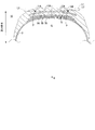
- FIG. 4 is an enlarged cross-sectional view showing the tire 10 in a state where the tire 1 is filled with air of a specified internal pressure.
- the tire 10 when compared with the tire 1 to which the internal pressure shown in FIG. 1 is not applied, the tire 10 has a tread portion Tt that expands radially outward about the CL and is displaced in an arc shape.
- the tread portion Tt is displaced, the plurality of belts 5A to 5C constituting the belt reinforcing body 6 and the belt layer 5 disposed therein are similarly deformed.
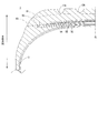
- the belt reinforcement body 6 is newly provided by setting the tread application surface B1 described in the above-described embodiment to be radially outward from the belt reinforcement body 6 provided in the tread rubber layer 7.
- the belt reinforcing body 6 exists in advance in the radial direction from the groove bottoms 11A to 14A of the tread grooves 11 to 14 existing in the tire 10 in the air-filled state. It is preferable to dispose the belt reinforcement 6.
- the belt reinforcement 6 is not exposed on the surface even if the tread grooves 11 to 14 are removed by the first rehabilitation, and the belt reinforcing body 6 is not damaged. Or it becomes possible to affix a new tread rubber 7 without passing through replacement work.
- the tire 10 in which four tread grooves are formed in the tire width direction is taken as an example.
- the present invention is not limited to this, and the tire has two tread grooves symmetrically formed around the CL.
- a tire in which a single tread groove is formed may be used.
- the shape of the groove bottom is not limited to the above example, and any other shape such as a rectangular cross-section, a V-shape or the like is assumed.
- the belt reinforcing body 6 is not disposed in the tread portion Tt of the tire 1 in the present embodiment, and the restraining member positioned at the outermost radial direction is the belt 5 ⁇ / b> A constituting the belt layer 5.
- the belt reinforcing body 6 is not disposed in the tread portion Tt of the tire 1 in the present embodiment, and the restraining member positioned at the outermost radial direction is the belt 5 ⁇ / b> A constituting the belt layer 5.
- Even such a tire 1 can be applied to the manufacturing method according to the above-described embodiment.
- the tread application surface B1 formed by the first rehabilitation of the tire 1 is radially inward from the groove bottoms 11A to 14A of the tread grooves 11 to 14 formed in the tread rubber 7, and the tread portion Tt. Is formed on the outer side in the radial direction from the outermost belt 5 ⁇ / b> A in the radial direction.
- the tread application surface B2 formed by the second rehabilitation is formed on the radially inner side of the belt 5A inserted radially outward and on the radially outer side of the belt 5B. Therefore, the outermost belt 5A in the radial direction is removed and a new belt 5A is provided by forming the tread application surface B2.
- the tread pasting surface B3 formed by the third rehabilitation is formed radially inside the tread pasting surface B2 and radially outside the belt 5B. Therefore, the formation of the tread application surface B3 removes the radially outermost belt 5A disposed in the second configuration, and the belt 5B radially inward of the belt 5A is not cut.
- the tread application surface B may be formed from the radially inner side toward the radially outer side in accordance with an increase in the number of times the tire 1 has been rehabilitated.
- the position where the tread application surface B is formed is changed from the radially outer side to the inner side of the tire 1 in accordance with the increase in the number of times the tire 1 is regenerated.
- the tread pasting surface B can be removed, and the tread pasting surface B formed in the past does not remain in the tire 1 after rehabilitation, and the durability of the tire 1 can be improved.
- the tread application surface B is formed at the outer side in the radial direction from the belt 5A positioned at the outermost side in the radial direction at least once, it is economically advantageous.
- the position of 5 A of belts located in the radial direction outermost is located inside radial direction rather than the virtual line L3 mentioned above. If it is set in advance, it is not necessary to replace the belt 5A by at least the first rehabilitation.
Landscapes
- Engineering & Computer Science (AREA)
- Mechanical Engineering (AREA)
- Tyre Moulding (AREA)
- Tires In General (AREA)
Priority Applications (3)
| Application Number | Priority Date | Filing Date | Title |
|---|---|---|---|
| US14/112,967 US9327465B2 (en) | 2011-04-21 | 2012-04-16 | Retreaded tire manufacturing method and tires suited therefor |
| EP12774528.9A EP2700496B1 (de) | 2011-04-21 | 2012-04-16 | Reifen-neuherstellungsverfahren |
| CN201280019322.XA CN103476575B (zh) | 2011-04-21 | 2012-04-16 | 翻新轮胎的制造方法以及适用于该制造方法的轮胎 |
Applications Claiming Priority (2)
| Application Number | Priority Date | Filing Date | Title |
|---|---|---|---|
| JP2011095199A JP6000516B2 (ja) | 2011-04-21 | 2011-04-21 | 更生タイヤの製造方法 |
| JP2011-095199 | 2011-04-21 |
Publications (1)
| Publication Number | Publication Date |
|---|---|
| WO2012144459A1 true WO2012144459A1 (ja) | 2012-10-26 |
Family
ID=47041565
Family Applications (1)
| Application Number | Title | Priority Date | Filing Date |
|---|---|---|---|
| PCT/JP2012/060268 Ceased WO2012144459A1 (ja) | 2011-04-21 | 2012-04-16 | 更生タイヤの製造方法及び当該製造方法に適したタイヤ |
Country Status (5)
| Country | Link |
|---|---|
| US (1) | US9327465B2 (de) |
| EP (1) | EP2700496B1 (de) |
| JP (1) | JP6000516B2 (de) |
| CN (1) | CN103476575B (de) |
| WO (1) | WO2012144459A1 (de) |
Families Citing this family (3)
| Publication number | Priority date | Publication date | Assignee | Title |
|---|---|---|---|---|
| JP6047060B2 (ja) * | 2013-04-23 | 2016-12-21 | 株式会社ブリヂストン | 航空機用空気入りタイヤ |
| JP2024151623A (ja) * | 2023-04-12 | 2024-10-25 | 住友ゴム工業株式会社 | 更生タイヤの製造方法及び更生タイヤ |
| DE102024207538A1 (de) | 2024-08-08 | 2026-02-12 | Continental Reifen Deutschland Gmbh | Verfahren zum Herstellen eines vorvulkanisierten Laufstreifens, vorvulkanisierter Laufstreifen und Fahrzeugreifen mit vorvulkanisierten Laufstreifen |
Citations (4)
| Publication number | Priority date | Publication date | Assignee | Title |
|---|---|---|---|---|
| JPS61233528A (ja) * | 1985-04-09 | 1986-10-17 | Bridgestone Corp | 航空機用タイヤの更生方法 |
| JPS63281832A (ja) * | 1987-05-15 | 1988-11-18 | Bridgestone Corp | 更正タイヤの製造方法およびその装置 |
| JPH08309881A (ja) * | 1995-05-22 | 1996-11-26 | Bridgestone Corp | 更生タイヤ判定方法 |
| JP2010247660A (ja) | 2009-04-15 | 2010-11-04 | Bridgestone Corp | 航空機用空気入りタイヤ |
Family Cites Families (13)
| Publication number | Priority date | Publication date | Assignee | Title |
|---|---|---|---|---|
| US3991803A (en) * | 1974-11-11 | 1976-11-16 | The B. F. Goodrich Company | Pneumatic tire with reinforced tread |
| US4218277A (en) * | 1975-12-17 | 1980-08-19 | Der Burg Sjirk Van | Tire retreading method including adding reinforcing belt |
| US4258776A (en) * | 1979-01-29 | 1981-03-31 | The Goodyear Tire & Rubber Company | Retreaded tire, method and apparatus |
| BE894599A (nl) * | 1982-10-05 | 1983-04-05 | Bekaert Sa Nv | Werkwijze en inrichting voor het verwijderen van tenminste een laag versterkingselementen van een breker of gordel van een rubberband |
| DE3623127A1 (de) * | 1986-07-09 | 1988-01-28 | Ihle Reifen Gmbh | Vorrichtung zum entfernen beschaedigter stahlguertellagen von reifen |
| JPH0813470B2 (ja) * | 1987-10-07 | 1996-02-14 | 株式会社ブリヂストン | タイヤの更生方法 |
| AU9075291A (en) * | 1990-11-20 | 1992-06-11 | Oliver Rubber Company | Method for rebelting tires |
| JPH11207831A (ja) * | 1998-01-28 | 1999-08-03 | Yokohama Rubber Co Ltd:The | 更生タイヤ用ベルト材料とその製造方法 |
| JP2005178038A (ja) * | 2003-12-16 | 2005-07-07 | Sumitomo Rubber Ind Ltd | 更生タイヤの製造方法及びプレキュアトレッド体 |
| EP1757463B1 (de) * | 2005-08-22 | 2012-06-13 | Bridgestone Corporation | Rundzuerneuernder Reifen und Herstellungsverfahren |
| US9539778B2 (en) * | 2007-11-28 | 2017-01-10 | The Goodyear Tire & Rubber Company | Pneumatic tire and a process to retread a tire |
| JP2010260312A (ja) * | 2009-05-11 | 2010-11-18 | Bridgestone Corp | タイヤ製造装置及びタイヤ製造方法 |
| JP5313049B2 (ja) * | 2009-05-28 | 2013-10-09 | 東洋ゴム工業株式会社 | 空気入りラジアルタイヤの製造方法 |
-
2011
- 2011-04-21 JP JP2011095199A patent/JP6000516B2/ja not_active Expired - Fee Related
-
2012
- 2012-04-16 EP EP12774528.9A patent/EP2700496B1/de not_active Not-in-force
- 2012-04-16 US US14/112,967 patent/US9327465B2/en active Active
- 2012-04-16 WO PCT/JP2012/060268 patent/WO2012144459A1/ja not_active Ceased
- 2012-04-16 CN CN201280019322.XA patent/CN103476575B/zh active Active
Patent Citations (4)
| Publication number | Priority date | Publication date | Assignee | Title |
|---|---|---|---|---|
| JPS61233528A (ja) * | 1985-04-09 | 1986-10-17 | Bridgestone Corp | 航空機用タイヤの更生方法 |
| JPS63281832A (ja) * | 1987-05-15 | 1988-11-18 | Bridgestone Corp | 更正タイヤの製造方法およびその装置 |
| JPH08309881A (ja) * | 1995-05-22 | 1996-11-26 | Bridgestone Corp | 更生タイヤ判定方法 |
| JP2010247660A (ja) | 2009-04-15 | 2010-11-04 | Bridgestone Corp | 航空機用空気入りタイヤ |
Non-Patent Citations (1)
| Title |
|---|
| See also references of EP2700496A4 * |
Also Published As
| Publication number | Publication date |
|---|---|
| EP2700496A4 (de) | 2015-12-30 |
| CN103476575B (zh) | 2015-12-09 |
| JP2012224026A (ja) | 2012-11-15 |
| US20140045410A1 (en) | 2014-02-13 |
| EP2700496B1 (de) | 2017-01-04 |
| EP2700496A1 (de) | 2014-02-26 |
| US9327465B2 (en) | 2016-05-03 |
| JP6000516B2 (ja) | 2016-09-28 |
| CN103476575A (zh) | 2013-12-25 |
Similar Documents
| Publication | Publication Date | Title |
|---|---|---|
| EP2448753B1 (de) | Runderneuerter reifen mit einem auf basisprofil abgestimmten reifenprofil und verfahren zu dessen herstellung | |
| US8636044B2 (en) | Reduced weight precured tread band for retreaded tire | |
| EP2448751B1 (de) | Runderneuerter reifen und verfahren zu dessen herstellung | |
| CN103587134A (zh) | 无套筒的轮胎成型鼓 | |
| JP6000516B2 (ja) | 更生タイヤの製造方法 | |
| WO2015100060A1 (en) | Precured tire tread with fabric reinforcing layer | |
| JP5790213B2 (ja) | 更生タイヤ及びその製造方法 | |
| JP2018114781A (ja) | 更生タイヤ | |
| JP2005219523A (ja) | 航空機用空気入りラジアルタイヤ | |
| JP2011025853A (ja) | タイヤ及びタイヤの更生方法 | |
| JP2010173139A (ja) | 台タイヤの製造方法と更生用トレッド及び更生タイヤ | |
| JP2012224026A5 (de) | ||
| JP5188936B2 (ja) | 航空機用更生タイヤおよびその製造方法 | |
| JP2011020508A (ja) | タイヤ、台タイヤ、及び、トレッド | |
| JP5884317B2 (ja) | プレキュアトレッド、更生タイヤ及びその製造方法 | |
| JP2008188819A (ja) | 空気入りタイヤ及びその製造方法 | |
| JP2017202792A (ja) | 更生タイヤ | |
| JP2007216634A (ja) | 更生タイヤの製造方法、及び更生タイヤ | |
| JP2013071556A (ja) | 空気入りタイヤおよび空気入りタイヤの更生方法 | |
| JP3051456B2 (ja) | 空気入りラジアルタイヤの更生方法 | |
| JP2013220601A (ja) | 未加硫タイヤトレッド及びタイヤトレッドの製造方法 | |
| JP2005178038A (ja) | 更生タイヤの製造方法及びプレキュアトレッド体 | |
| JP5184067B2 (ja) | 航空機用更生タイヤ製造方法及び更生用モールド | |
| JP2000301627A (ja) | 更生タイヤの製造方法 | |
| CN1984786A (zh) | 充气轮胎 |
Legal Events
| Date | Code | Title | Description |
|---|---|---|---|
| 121 | Ep: the epo has been informed by wipo that ep was designated in this application |
Ref document number: 12774528 Country of ref document: EP Kind code of ref document: A1 |
|
| NENP | Non-entry into the national phase |
Ref country code: DE |
|
| WWE | Wipo information: entry into national phase |
Ref document number: 14112967 Country of ref document: US |
|
| REEP | Request for entry into the european phase |
Ref document number: 2012774528 Country of ref document: EP |
|
| WWE | Wipo information: entry into national phase |
Ref document number: 2012774528 Country of ref document: EP |