WO2012144514A1 - Dispositif de source de lumière de surface, procédé pour sa fabrication, dispositif d'affichage le comportant, et dispositif d'éclairage le comportant - Google Patents
Dispositif de source de lumière de surface, procédé pour sa fabrication, dispositif d'affichage le comportant, et dispositif d'éclairage le comportant Download PDFInfo
- Publication number
- WO2012144514A1 WO2012144514A1 PCT/JP2012/060429 JP2012060429W WO2012144514A1 WO 2012144514 A1 WO2012144514 A1 WO 2012144514A1 JP 2012060429 W JP2012060429 W JP 2012060429W WO 2012144514 A1 WO2012144514 A1 WO 2012144514A1
- Authority
- WO
- WIPO (PCT)
- Prior art keywords
- light
- light source
- source device
- main surface
- light guide
- Prior art date
- Legal status (The legal status is an assumption and is not a legal conclusion. Google has not performed a legal analysis and makes no representation as to the accuracy of the status listed.)
- Ceased
Links
Images


Classifications
-
- G—PHYSICS
- G02—OPTICS
- G02F—OPTICAL DEVICES OR ARRANGEMENTS FOR THE CONTROL OF LIGHT BY MODIFICATION OF THE OPTICAL PROPERTIES OF THE MEDIA OF THE ELEMENTS INVOLVED THEREIN; NON-LINEAR OPTICS; FREQUENCY-CHANGING OF LIGHT; OPTICAL LOGIC ELEMENTS; OPTICAL ANALOGUE/DIGITAL CONVERTERS
- G02F1/00—Devices or arrangements for the control of the intensity, colour, phase, polarisation or direction of light arriving from an independent light source, e.g. switching, gating or modulating; Non-linear optics
- G02F1/01—Devices or arrangements for the control of the intensity, colour, phase, polarisation or direction of light arriving from an independent light source, e.g. switching, gating or modulating; Non-linear optics for the control of the intensity, phase, polarisation or colour
- G02F1/13—Devices or arrangements for the control of the intensity, colour, phase, polarisation or direction of light arriving from an independent light source, e.g. switching, gating or modulating; Non-linear optics for the control of the intensity, phase, polarisation or colour based on liquid crystals, e.g. single liquid crystal display cells
- G02F1/133—Constructional arrangements; Operation of liquid crystal cells; Circuit arrangements
- G02F1/1333—Constructional arrangements; Manufacturing methods
- G02F1/1335—Structural association of cells with optical devices, e.g. polarisers or reflectors
- G02F1/1336—Illuminating devices
- G02F1/133602—Direct backlight
- G02F1/133603—Direct backlight with LEDs
-
- G—PHYSICS
- G02—OPTICS
- G02B—OPTICAL ELEMENTS, SYSTEMS OR APPARATUS
- G02B6/00—Light guides; Structural details of arrangements comprising light guides and other optical elements, e.g. couplings
- G02B6/0001—Light guides; Structural details of arrangements comprising light guides and other optical elements, e.g. couplings specially adapted for lighting devices or systems
- G02B6/0011—Light guides; Structural details of arrangements comprising light guides and other optical elements, e.g. couplings specially adapted for lighting devices or systems the light guides being planar or of plate-like form
- G02B6/0033—Means for improving the coupling-out of light from the light guide
- G02B6/005—Means for improving the coupling-out of light from the light guide provided by one optical element, or plurality thereof, placed on the light output side of the light guide
-
- G—PHYSICS
- G02—OPTICS
- G02F—OPTICAL DEVICES OR ARRANGEMENTS FOR THE CONTROL OF LIGHT BY MODIFICATION OF THE OPTICAL PROPERTIES OF THE MEDIA OF THE ELEMENTS INVOLVED THEREIN; NON-LINEAR OPTICS; FREQUENCY-CHANGING OF LIGHT; OPTICAL LOGIC ELEMENTS; OPTICAL ANALOGUE/DIGITAL CONVERTERS
- G02F1/00—Devices or arrangements for the control of the intensity, colour, phase, polarisation or direction of light arriving from an independent light source, e.g. switching, gating or modulating; Non-linear optics
- G02F1/01—Devices or arrangements for the control of the intensity, colour, phase, polarisation or direction of light arriving from an independent light source, e.g. switching, gating or modulating; Non-linear optics for the control of the intensity, phase, polarisation or colour
- G02F1/13—Devices or arrangements for the control of the intensity, colour, phase, polarisation or direction of light arriving from an independent light source, e.g. switching, gating or modulating; Non-linear optics for the control of the intensity, phase, polarisation or colour based on liquid crystals, e.g. single liquid crystal display cells
- G02F1/133—Constructional arrangements; Operation of liquid crystal cells; Circuit arrangements
- G02F1/1333—Constructional arrangements; Manufacturing methods
- G02F1/1335—Structural association of cells with optical devices, e.g. polarisers or reflectors
- G02F1/1336—Illuminating devices
- G02F1/133615—Edge-illuminating devices, i.e. illuminating from the side
-
- G—PHYSICS
- G02—OPTICS
- G02B—OPTICAL ELEMENTS, SYSTEMS OR APPARATUS
- G02B6/00—Light guides; Structural details of arrangements comprising light guides and other optical elements, e.g. couplings
- G02B6/0001—Light guides; Structural details of arrangements comprising light guides and other optical elements, e.g. couplings specially adapted for lighting devices or systems
- G02B6/0011—Light guides; Structural details of arrangements comprising light guides and other optical elements, e.g. couplings specially adapted for lighting devices or systems the light guides being planar or of plate-like form
- G02B6/0013—Means for improving the coupling-in of light from the light source into the light guide
- G02B6/0023—Means for improving the coupling-in of light from the light source into the light guide provided by one optical element, or plurality thereof, placed between the light guide and the light source, or around the light source
- G02B6/0025—Diffusing sheet or layer; Prismatic sheet or layer
-
- G—PHYSICS
- G02—OPTICS
- G02B—OPTICAL ELEMENTS, SYSTEMS OR APPARATUS
- G02B6/00—Light guides; Structural details of arrangements comprising light guides and other optical elements, e.g. couplings
- G02B6/0001—Light guides; Structural details of arrangements comprising light guides and other optical elements, e.g. couplings specially adapted for lighting devices or systems
- G02B6/0011—Light guides; Structural details of arrangements comprising light guides and other optical elements, e.g. couplings specially adapted for lighting devices or systems the light guides being planar or of plate-like form
- G02B6/0013—Means for improving the coupling-in of light from the light source into the light guide
- G02B6/0023—Means for improving the coupling-in of light from the light source into the light guide provided by one optical element, or plurality thereof, placed between the light guide and the light source, or around the light source
- G02B6/0028—Light guide, e.g. taper
-
- G—PHYSICS
- G02—OPTICS
- G02B—OPTICAL ELEMENTS, SYSTEMS OR APPARATUS
- G02B6/00—Light guides; Structural details of arrangements comprising light guides and other optical elements, e.g. couplings
- G02B6/0001—Light guides; Structural details of arrangements comprising light guides and other optical elements, e.g. couplings specially adapted for lighting devices or systems
- G02B6/0011—Light guides; Structural details of arrangements comprising light guides and other optical elements, e.g. couplings specially adapted for lighting devices or systems the light guides being planar or of plate-like form
- G02B6/0013—Means for improving the coupling-in of light from the light source into the light guide
- G02B6/0023—Means for improving the coupling-in of light from the light source into the light guide provided by one optical element, or plurality thereof, placed between the light guide and the light source, or around the light source
- G02B6/0031—Reflecting element, sheet or layer
-
- G—PHYSICS
- G02—OPTICS
- G02B—OPTICAL ELEMENTS, SYSTEMS OR APPARATUS
- G02B6/00—Light guides; Structural details of arrangements comprising light guides and other optical elements, e.g. couplings
- G02B6/0001—Light guides; Structural details of arrangements comprising light guides and other optical elements, e.g. couplings specially adapted for lighting devices or systems
- G02B6/0011—Light guides; Structural details of arrangements comprising light guides and other optical elements, e.g. couplings specially adapted for lighting devices or systems the light guides being planar or of plate-like form
- G02B6/0066—Light guides; Structural details of arrangements comprising light guides and other optical elements, e.g. couplings specially adapted for lighting devices or systems the light guides being planar or of plate-like form characterised by the light source being coupled to the light guide
- G02B6/0068—Arrangements of plural sources, e.g. multi-colour light sources
-
- G—PHYSICS
- G02—OPTICS
- G02F—OPTICAL DEVICES OR ARRANGEMENTS FOR THE CONTROL OF LIGHT BY MODIFICATION OF THE OPTICAL PROPERTIES OF THE MEDIA OF THE ELEMENTS INVOLVED THEREIN; NON-LINEAR OPTICS; FREQUENCY-CHANGING OF LIGHT; OPTICAL LOGIC ELEMENTS; OPTICAL ANALOGUE/DIGITAL CONVERTERS
- G02F1/00—Devices or arrangements for the control of the intensity, colour, phase, polarisation or direction of light arriving from an independent light source, e.g. switching, gating or modulating; Non-linear optics
- G02F1/01—Devices or arrangements for the control of the intensity, colour, phase, polarisation or direction of light arriving from an independent light source, e.g. switching, gating or modulating; Non-linear optics for the control of the intensity, phase, polarisation or colour
- G02F1/13—Devices or arrangements for the control of the intensity, colour, phase, polarisation or direction of light arriving from an independent light source, e.g. switching, gating or modulating; Non-linear optics for the control of the intensity, phase, polarisation or colour based on liquid crystals, e.g. single liquid crystal display cells
- G02F1/133—Constructional arrangements; Operation of liquid crystal cells; Circuit arrangements
- G02F1/1333—Constructional arrangements; Manufacturing methods
- G02F1/1335—Structural association of cells with optical devices, e.g. polarisers or reflectors
- G02F1/1336—Illuminating devices
- G02F1/133602—Direct backlight
- G02F1/133606—Direct backlight including a specially adapted diffusing, scattering or light controlling members
- G02F1/133607—Direct backlight including a specially adapted diffusing, scattering or light controlling members the light controlling member including light directing or refracting elements, e.g. prisms or lenses
Definitions
- the present invention relates to a surface light source device, a manufacturing method thereof, a display device, and an illumination device.
- a transmissive liquid crystal display device that performs display using light emitted from a surface light source device.
- This type of liquid crystal display device has a liquid crystal panel and a surface light source device disposed on the back side of the liquid crystal panel.
- a conventional surface light source device includes a light source such as a light emitting diode (hereinafter, abbreviated as LED) and a light guide plate.
- LED light emitting diode
- the light emitted from the light source is propagated inside the light guide plate and emitted from the entire surface of the light guide plate.
- the surface light source device provided on the back side of the display panel may be referred to as a backlight.
- a backlight device including a light generation device, a light guide plate, a microprism, and a microlens array is disclosed (Patent Document 1 below). reference).
- the light emitted from the light generating device enters the microprism while propagating through the light guide plate, the light is reflected by the microprism and the traveling direction is changed, and is extracted to the front. Further, the light emitted from the microprism enters the microlens array, and the parallelism is increased by each microlens and is emitted from the backlight device.
- An aspect of the present invention has been made to solve the above-described problem, and an object thereof is to provide a surface light source device that can obtain light with high directivity.
- An object is to provide a low-cost surface light source device.
- An object of the present invention is to provide a method for manufacturing this type of surface light source device. It is an object of the present invention to provide a display device and an illumination device provided with this type of surface light source device.
- a surface light source device includes a light source, a first main surface, and a second main surface, and the light emitted from the light source is the first main surface.
- a reflection part that changes the traveling direction of the light and re-enters the light guide to be emitted from the first main surface
- the reflection unit includes the second main surface of the light guide and A concave mirror having a reflective surface facing each other and having a focal point in a plane parallel to the light propagation direction and perpendicular to the second main surface, and in contact with the second main surface of the light guide Of the light that is provided at a position including the focal point of the concave mirror and propagates through the light guide to reach the second main surface, Focal or by transmitting light through the vicinity of the focal point and a light transmitting
- the surface light source device further includes a convex lens in a recess of the concave mirror, and the mutually opposing surfaces of the light guide and the convex lens are spaced apart from each other, and the light guide and the convex lens May be connected via the light transmission part.
- the planar shape of the concave mirror viewed from the normal direction of the second main surface of the light guide may be circular.
- the light source may be provided on a first end surface and a second end surface of the light guide that face each other.
- the planar shape of the concave mirror viewed from the normal direction of the second main surface of the light guide may be substantially semicircular.
- the light source is provided on the first end surface of the light guide, and the concave mirror is disposed so that the substantially semicircular straight side of the planar shape faces the first end surface. May be.
- the concave mirror has a curvature in a direction parallel to the light propagation direction, and a curvature in a direction perpendicular to the light propagation direction and parallel to the second main surface.
- the light transmission part may extend in a direction perpendicular to the light propagation direction and parallel to the second main surface.
- the surface light source device may be provided with a plurality of the concave mirrors.
- the planar dimensions of at least some of the concave mirrors may be different from the planar dimensions of other concave mirrors.
- the arrangement density of the plurality of concave mirrors may be sequentially increased along the light propagation direction.
- the planar shape of the concave mirror viewed from the normal direction of the second main surface of the light guide is a polygon, and the adjacent polygons are in close contact with each other. It may be arranged.
- the light source may impart directivity to the emitted light in a direction perpendicular to the light propagation direction and parallel to the second main surface.
- the light source has a size in the direction parallel to the light propagation direction that is successively smaller along the direction perpendicular to the light propagation direction and parallel to the second main surface.
- a wedge-shaped light guide member may be provided.
- the light source includes a light emitting element and a mirror that reflects light emitted from the light emitting element, and the mirror is parallel to the second main surface of the light guide.
- the light emitting element is disposed such that the focal point is located on a light emitting surface, and light from the light emitting element is incident on the light guide through the mirror. Good.
- a method of manufacturing a surface light source device including manufacturing a mirror lens having a concave mirror having a focal point on one surface of a convex lens, and applying a photocurable resin to the other surface of the convex lens.
- a display device includes the above-described surface light source device and a display element that performs display using light emitted from the surface light source device.
- An illumination device includes the surface light source device of the present invention.
- a surface light source device that can obtain light with high directivity.
- a low-cost surface light source device can be provided.
- the method of manufacturing this kind of surface light source device can be provided.
- a display apparatus and an illuminating device provided with this kind of surface light source device can be provided.
- FIG. 3 is a cross-sectional view taken along line A-A ′ of FIG. 2. It is a figure which shows the manufacturing process of the surface light source device of this embodiment. It is a figure which shows the manufacturing process of the surface light source device of this embodiment. It is a figure which shows the manufacturing process of the surface light source device of this embodiment. It is a figure which shows the manufacturing process of the surface light source device of this embodiment. It is a figure which shows the manufacturing process of the surface light source device of this embodiment. It is a figure which shows the manufacturing process of the surface light source device of this embodiment. It is a figure which shows the brightness
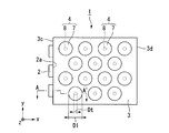
- FIG. 1 is a perspective view showing the surface light source device of this embodiment.
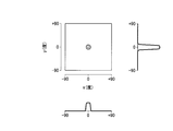
- FIG. 2 is a plan view showing the surface light source device of the present embodiment.
- FIG. 3 is a cross-sectional view taken along the line AA ′ of FIG.
- FIG. 4 is a diagram showing a manufacturing process of the surface light source device of this embodiment.
- the scale of the size may be varied depending on the component.
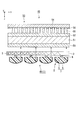
- the surface light source device 1 includes a plurality of LEDs 2 (light sources), a light guide 3 and a plurality of reflecting portions 4 as shown in FIG.
- Each reflecting portion 4 includes a mirror lens 7 and a light transmitting portion 8.
- the light guide 3 has a function of causing the light emitted from the LED 2 to enter and propagating the inside while totally reflecting between the first main surface 3a and the second main surface 3b.
- the reflection unit 4 reflects a part of light emitted from the second main surface 3b out of the light propagating through the light guide 3, changes the traveling direction of the light, and re-enters the light guide 3. And has a function of injecting from the first main surface 3a. In order to make the drawing easier to see, only 14 reflecting portions 4 are shown on the light guide 3 in the drawing, but actually, a larger number of reflecting portions 4 are provided.
- the light guide 3 is a plate made of a resin having optical transparency such as acrylic resin. 2 and 3, among the six surfaces of the light guide 3, the two main surfaces 3a and 3b facing each other are parallel, and the two end surfaces 3c and 3d facing each other are parallel.
- a plurality (three in this embodiment) of LEDs 2 are installed on one end surface 3 c of the light guide plate 3.
- the light emission surface 2 a of each LED 2 faces the end surface 3 c of the light guide plate 3. Therefore, of the two end faces 3c and 3d of the light guide plate 3, the end face 3c on the side where the LED 2 is provided becomes a light incident end face on which the light emitted from each LED 2 is incident.
- the end surface 3c on the side where the LED 2 is provided is referred to as a first end surface
- the end surface 3d on the side where the LED 2 is not provided is referred to as a second end surface.
- LED2 of this embodiment does not have directivity. Therefore, the LED 2 emits diffused light having a predetermined divergence angle.
- a plurality of reflecting portions 4 are provided on one main surface 3 b.
- the planar shape of the reflecting portion 4 viewed from the normal direction of the main surface 3b is a circle.
- the plurality of reflecting portions 4 are two-dimensionally arranged in two directions (x-axis direction and y-axis direction) orthogonal to each other in the plane of the main surface 3 b. If the distance between the centers of the adjacent reflecting portions 4 is 1 pitch, the plurality of reflecting portions 4 in adjacent rows are arranged at positions shifted by 1/2 pitch in the row direction.
- the other main surface 3a of the light guide plate 3 serves as a light emitting surface for emitting the light reflected by the plurality of reflecting portions 4, as shown in FIG.
- the main surface 3a on the side where the reflecting portion 4 is not provided is referred to as a first main surface
- the main surface 3b on the side where the reflecting portion 4 is provided is referred to as a second main surface.
- the light propagation direction in the first main surface 3a of the light guide 3 is the x-axis direction
- the direction orthogonal to the light propagation direction is the y-axis direction
- the first main surface 3a is orthogonal.
- the direction (thickness direction of the light guide 3) is defined as the z-axis direction. Therefore, “the propagation direction of light” in the present specification means the direction in which light (indicated by the dashed line arrow L) propagates while reflecting in the xz section of the light guide 3 shown in FIG. Instead, it means a direction (indicated by a solid arrow X) in which light propagates when viewed from the normal direction of the first main surface 3a of the light guide 3.
- Each reflection part 4 is comprised from the mirror lens 7 which consists of the convex lens 5 and the concave mirror 6, and the light transmissive part 8, as shown in FIG.
- the convex lens 5 is made of a light-transmitting resin such as an acrylic resin.
- the convex lens 5 is a so-called plano-convex lens in which one surface 5a is a flat surface (light emission surface) and the other surface 5b is a paraboloid (reflection surface).
- the concave mirror 6 is composed of a metal thin film with high reflectivity, such as aluminum, formed along the paraboloid 5b of the convex lens 5.
- the shape of the top part into which the light L injects is a paraboloid shape
- the shape of a side part is a cylindrical shape.
- the range in which the light L is incident through the light transmitting portion 8 may be at least parabolic, but the entire concave mirror 6 may be parabolic.
- the concave mirror 6 has a paraboloid at least in part, it has a focal point.
- the light transmitting portion 8 is a columnar member made of a resin having a light transmission property such as an acrylic resin. As will be described later, it is desirable that the light transmissive resin used for the light transmissive portion 8 has ultraviolet curability.
- the light transmissive resin used for the light transmissive portion 8 may be the same as or different from the light transmissive resin used for the convex lens 5. Therefore, the refractive index of the light transmitting resin used for the light transmitting portion 8 and the refractive index of the light transmitting resin used for the convex lens 5 may be the same or different.
- the light transmission unit 8 has a function of connecting the light guide 3 and the mirror lens 7 and guiding the light L propagating through the light guide 3 to the mirror lens 7.
- the mirror lens 7 is connected to the light guide 3 by the light transmitting portion 8 with the flat lens 5 side of the convex lens 5 facing the second main surface 3 b of the light guide 3.
- the diameter Dt of the light transmission part 8 is sufficiently smaller than the diameter of the mirror lens D1
- the light transmission part 8 has only the focal point S of the concave mirror 6 and its vicinity as shown in FIG. Is provided.
- the focal point S of the concave mirror 6 is preferably located at the interface between the light transmission part 8 and the mirror lens 7, but may be located inside the light transmission part 8, or may be guided to the light transmission part 8.
- the plane 5a of the convex lens 5 and the second main surface 3b of the light guide 3 are separated from each other, and air 9 is in the space sandwiched between the plane 5a of the convex lens 5 and the second main surface 3b of the light guide 3. Existing.
- the surface light source device 1 having the above configuration
- a method for manufacturing the surface light source device 1 having the above configuration For example, after producing the convex lens 5 made of a light-transmitting resin using a technique such as injection molding, a metal thin film such as aluminum is formed on the paraboloid 5b of the convex lens 5 using a sputtering method or the like, The mirror lens 7 is produced by forming the concave mirror 6.
- an ultraviolet curable resin (photo curable resin) is applied to one surface (plane 5a) of the mirror lens 7 to form an ultraviolet curable resin film 10 (photo curable resin film).
- the film thickness of the ultraviolet curable resin film 10 with respect to the shape of the paraboloid 5b is adjusted so that the focal point S of the concave mirror 6 is located on the upper surface, the lower surface, or the inside of the ultraviolet curable resin film 10.
- the ultraviolet ray UV is irradiated to the concave mirror 6 through the ultraviolet curable resin film 10 and the convex lens 5 with such a weak intensity that the curing of the ultraviolet curable resin film 10 does not start.
- the intensity of the ultraviolet ray UV is weak, the ultraviolet curable resin is not cured to the extent that the ultraviolet ray UV passes through the ultraviolet curable resin film 10 once.
- the reflected ultraviolet ray UV is condensed at the position of the focal point S.
- the intensity of the ultraviolet rays UV is increased at the focal point S and in the vicinity thereof, the ultraviolet curable resin film 10 is cured.
- the ultraviolet curable resin film 10 after being irradiated with the ultraviolet UV is developed.
- This remaining portion becomes a light transmission portion 8 that connects the mirror lens 7 and the light guide 3.
- the reflection part 4 is completed by the steps so far.
- the reflecting portion 4 is bonded and fixed to the light guide 3 via the light transmitting portion 8.
- the light L emitted from the LED 2 is diffused light having a certain extent.
- the light from the LED 2 travels from the first end surface 3c side to the second end surface 3d side while repeating total reflection between the first main surface 3a and the second main surface 3b of the light guide 3.
- the refractive index of the light-transmitting resin for example, acrylic resin
- the first main surface 3a and the second main surface 3b of the light guide 3 are refracted. It becomes an interface between a light-transmitting resin having a refractive index of 1.5 and air having a refractive index of 1.0.
- the critical angle at the first main surface 3a and the second main surface 3b of the light guide 3 is approximately 42 degrees. That is, light having an incident angle ⁇ of 42 degrees or more with respect to the first main surface 3a and the second main surface 3b of the light guide 3 is totally reflected on the first main surface 3a and the second main surface 3b of the light guide 3. .
- the refractive index of the light transmitting resin (for example, acrylic resin) constituting the light transmission portion 8 is 1.5. If so, the second main surface 3b of the light guide 3 is an interface between a light-transmitting resin having a refractive index of 1.5 and a light-transmitting resin having a refractive index of 1.5. In this case, total reflection does not occur on the second main surface 3 b of the light guide 3. Therefore, like the light L shown in FIG. 3, only the light L that has reached the position of the light transmitting portion 8 can pass through the light transmitting portion 8 and enter the mirror lens 7.
- the light transmitting resin for example, acrylic resin
- the light incident on the mirror lens 7 is reflected by the concave mirror 6.
- the light L reflected by the concave mirror 6 travels in a direction substantially perpendicular to the second main surface 3b of the light guide 3. To do. That is, since at least a part of the light L passes through the focal point S of the concave mirror 6, the light L reflected by the concave mirror 6 is in a direction substantially perpendicular to the second main surface 3 b of the light guide 3. proceed.
- the light L reflected by the concave mirror 6 passes through the convex lens 5 and is then emitted from the first main surface 3a of the light guide 3 only in a direction substantially perpendicular to the first main surface 3a.
- the surface light source device 1 of the present embodiment light with high directivity can be obtained in the normal direction of the first main surface 3a of the light guide 3.
- the light L passes through the focal point S of the concave mirror 6 when at least part of the light L passes through the focal point S of the concave mirror 6.
- “near the focus” means a range in which the distance from the focus is within 0 to 10% of the diameter of the mirror lens 7. That is, “near the focus” means a range surrounded by a circle having a diameter of 10% of the diameter of the mirror lens 7 with the focus at the center. For example, when the diameter of the mirror lens 7 is 100 ⁇ m, “near the focus” means a range surrounded by a circle having a diameter of 10 ⁇ m with the focus at the center.
- the surface light source device 1 of the present embodiment can obtain light with high directivity in any azimuth angle direction.
- FIG. 5 is a diagram showing the simulation result.
- the angle of the emitted light is parallel to the first main surface 3a with reference to the front direction as viewed from the first main surface 3a of the light guide 3, that is, the normal direction of the first main surface 3a is 0 degrees, and the normal direction is the reference.
- the major directions were +90 degrees and -90 degrees. 5 corresponds to the x axis (light propagation direction) in the plan view of FIG. 2, and the y axis of FIG.
- the diameter Dl of the mirror lens 7 was 100 ⁇ m
- the radius of curvature of the paraboloid of the mirror lens 7 was 50 ⁇ m
- the diameter Dt of the columnar body of the light transmitting portion 8 was 5 ⁇ m.
- the light emitted from the light guide 3 has high directivity within 20 degrees in both the x-axis direction and the y-axis direction. From this, it is estimated that the light emitted from the light guide 3 has high directivity in all azimuth angles, not limited to the x-axis direction and the y-axis direction.
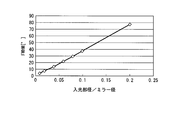
- the present inventors fixed the diameter Dl of the mirror lens 7 to 100 ⁇ m, the radius of curvature of the paraboloid of the mirror lens 7 to 50 ⁇ m, and the angle when the diameter Dt of the light transmission part 8 was changed. -The half width of the luminance profile was examined. The result is shown in FIG. 6 represents the ratio of the diameter Dt of the light transmission part 8 to the diameter Dl of the mirror lens 7, and the vertical axis of FIG. 6 represents the half-value width [degree].
- the ratio of the diameter Dt of the light transmitting portion 8 to the diameter Dl of the mirror lens 7 is preferably about 0.05.
- the ratio of the diameter Dt of the light transmission part 8 to the diameter Dl of the mirror lens 7 is preferably about 0.05.
- the diameter ratio the better.
- the diameter ratio is too small, the amount of light incident on the mirror lens 7 decreases, and the amount of light that can be extracted from the light guide 3 decreases.
- the UV light is irradiated with weak intensity through the UV curable resin film 10. Utilizing the fact that the irradiated ultraviolet ray UV is condensed at the focal point S when reflected by the concave mirror 6, the ultraviolet curable resin film 10 is left only at the focal point S and its vicinity, and this is used as the light transmitting portion 8. It is said. Therefore, the position of the light transmission part 8 with respect to the mirror lens 7 is determined in a self-aligning manner.
- the surface light source device 1 having high directivity can be manufactured with a high yield.
- a reflective film may be formed on the second end surface 3d of the light guide 3. In that case, the light reaching the second end surface 3d of the light guide 3 is reflected by the reflective film and returns toward the first end surface 3c. In the returning path, the light that has reached the light transmitting portion 8 can be taken out of the light guide 3. Further, a reflective film may be formed on the side surface of the light guide 3.
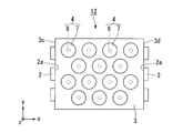
- FIG. 7 is a plan view of the surface light source device of the present embodiment, and corresponds to FIG. 2 of the first embodiment. In FIG. 7, the same components as those in FIG.
- the LED 2 is provided only on the first end surface 3 c of the light guide 3.
- a plurality of LEDs 2 are also provided on the second end surface 3 d of the light guide 3. Is provided.
- the number of the reflection parts 4 provided in the light guide 3 is the same as in the first embodiment.
- the surface light source device 12 of the present embodiment it is possible to obtain the same effect as that of the first embodiment that emitted light having high directivity can be obtained.
- the number of the reflection parts 4 is the same as that of the first embodiment, the light from the LED 2 provided on the first end surface 3c of the light guide 3 and the LED 2 provided on the second end surface 3d Since the light can be extracted by the same reflecting portion 4, an efficient surface light source device can be provided.
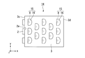
- FIG. 8 is a plan view of the surface light source device of this embodiment, and corresponds to FIG. 2 of the first embodiment. In FIG. 8, the same components as those in FIG.
- the circular reflecting portion 4 is provided when viewed from the normal direction of the second main surface 3b of the light guide 3.
- the surface light source device 14 of the present embodiment is provided with a substantially semicircular reflecting portion 15 when viewed from the normal direction of the second main surface 3b of the light guide 3, as shown in FIG. Yes.
- the light transmission part 8 is comprised with the cylindrical body similarly to 1st Embodiment. Therefore, the planar shape of the mirror lens 16 is substantially semicircular. Further, the mirror lens 16 is arranged so that the straight side of the semicircle that is the planar shape of the mirror lens 16 faces the first end surface 3 c of the light guide 3.
- the surface light source device 14 of the present embodiment it is possible to obtain the same effect as that of the first embodiment that emitted light having high directivity can be obtained. If only the light traveling from the LED 2 provided on the first end surface 3c of the light guide 3 to the second end surface 3d is used, the circular mirror lens 7 as in the first embodiment is used as in the present embodiment. Of these, half of the light guide 3 on the second end face 3d side is sufficient. According to the configuration of the present embodiment, since the area occupied by the mirror lens 16 is smaller than that of the first embodiment, the arrangement density of the mirror lenses 16 can be increased. As a result, the light extraction efficiency can be increased.
- FIG. 9 is a plan view of the surface light source device of this embodiment, and corresponds to FIG. 2 of the first embodiment. In FIG. 9, the same components as those in FIG.
- the circular reflection part 4 was provided seeing from the normal line direction of the 2nd main surface 3b of the light guide 3.
- the surface light source device 18 of the present embodiment is provided with a regular hexagonal reflection portion 19 on the second main surface 3 b of the light guide 3 when viewed from the normal direction.
- the light transmission part 8 is comprised with the cylindrical body similarly to 1st Embodiment. Therefore, the planar shape of the mirror lens 20 is a regular hexagon.
- the mirror lens 20 of the present embodiment is obtained by simply cutting the edge of a circular mirror lens similar to the first embodiment into a regular hexagon, and the top of the mirror lens 20 is the same as that of the first embodiment. Has a parabolic surface. Adjacent mirror lenses 20 are arranged in close contact so that regular hexagonal sides are in contact with each other.
- the plurality of mirror lenses 20 are formed of an integral light transmissive resin.
- the surface light source device 18 of the present embodiment it is possible to obtain the same effect as that of the first embodiment that emitted light having high directivity can be obtained.
- the arrangement density of the mirror lenses 20 can be increased.
- the light extraction efficiency can be increased.
- the plurality of mirror lenses 20 are formed of an integral light transmissive resin, handling becomes easy when the reflecting portion 19 is manufactured.
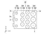
- FIG. 10 is a plan view of the surface light source device of this embodiment, and corresponds to FIG. 2 of the first embodiment. In FIG. 10, the same components as those in FIG.
- the dimensions of the plurality of reflecting portions 4 are equal, and the plurality of reflecting portions 4 are arranged uniformly over the entire light guide 3.
- the shapes of the reflecting portions 23a to 23d are all circular, but the dimensions of the plurality of reflecting portions 23a to 23d are different. Further, the arrangement of the plurality of reflecting portions 23a to 23d on the light guide 3 is uneven.
- the diameter of the mirror lens 24a located near the first end face 3c of the light guide 3 close to the LED 2 is small, and the diameter of the mirror lens 24d located near the second end face 3d of the light guide 3 far from the LED 2 Is set larger. Further, in all the reflecting portions 23a to 23d, the ratio of the diameter of the light transmitting portion 8 to the diameter of the mirror lenses 24a to 24d is equal. Therefore, the diameter of the light transmission part 8 located near the first end face 3c of the light guide 3 is set small, and the diameter of the light transmission part 8 located near the second end face 3d of the light guide 3 is set large.
- the arrangement density of the mirror lenses 24a located near the first end face 3c of the light guide 3 close to the LED 2 is small, and the arrangement density of the mirror lenses 24d located near the second end face 3d of the light guide 3 far from the LED 2 is low. It is set large.
- the surface light source device 22 of the present embodiment it is possible to obtain the same effect as that of the first embodiment that emitted light having high directivity can be obtained.
- the light emitted from the LED 2 travels from the first end surface 3c to the second end surface 3d of the light guide 3, when the plurality of reflecting portions are evenly arranged, the reflecting portion on the side closer to the LED 2 is first. In some cases, a large amount of light is extracted, and the amount of light extracted gradually decreases as the light advances. As a result, the luminance may be non-uniform in the plane.
- the luminance in the plane can be made uniform. it can.
- FIG. 11 is a cross-sectional view of the surface light source device of the present embodiment, and corresponds to FIG. 3 of the first embodiment. In FIG. 11, the same components as those in FIG.
- the convex lens 5 constituting the mirror lens 7 is connected to the light guide 3 via the light transmitting portion 8.
- the surface light source device 26 of the present embodiment has a hollow inside the concave mirror 6 and no convex lens.
- the light transmission part 27 of this embodiment does not transmit light linearly.
- the light transmitting portion 27 scatters the light L propagating through the light guide 3 and is composed of a scatterer that emits the light L toward the concave mirror 6.
- the light transmission part 27 is arranged so that the focal point S of the concave mirror 6 is located inside.
- the concave mirror 6 is supported by an arbitrary support means with a predetermined distance from the light guide 3.
- a plurality of concave mirrors 6 may be formed in close contact with each other, and the entirety thereof may be supported between the light guide 3 and a spacer or the like.
- the surface light source device 26 of the present embodiment only the light that has reached the light transmission part 27 out of the second main surface 3b of the light guide 3 is scattered inside the light transmission part 27 and the internal space of the concave mirror 6. To be taken out. Thereafter, the light L is reflected by the concave mirror 6, passes through the light guide 3, and is extracted in the front direction of the light guide 3. In this manner, similarly to the first to fifth embodiments, the surface light source device 26 of this embodiment can obtain emitted light with high directivity.
- FIG. 12 is a perspective view of the surface light source device of the present embodiment, and corresponds to FIG. 1 of the first embodiment.
- FIG. 13 is a plan view of the surface light source device of this embodiment, and corresponds to FIG. 2 of the first embodiment.
- the same reference numerals are given to the same components as those in FIG. 1 and FIG.
- the surface light source device 29 of the present embodiment includes a light source 30, a light guide 3, and a plurality of reflecting portions 31, as shown in FIG.
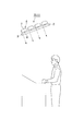
- the light source 30 includes an LED 32, a wedge-shaped prism 33, and a prism sheet 34.
- the reflection part 4 of the first embodiment has a circular planar shape when viewed from the normal direction of the light guide 3.
- the planar shape viewed from the normal direction of the light guide 3 extends in a band shape in a direction (y-axis direction) perpendicular to the light propagation direction.
- the LED 2 having no directivity is used.
- the LED 32 may not have directivity, but the light source 30 is parallel to the first main surface 3a of the light guide 3 as shown in FIG.
- the light L having directivity is emitted in a direction perpendicular to the propagation direction (y-axis direction).
- the LED 32 is disposed on an end surface 33 a of a wedge-shaped prism 33 having a right-angled triangle when viewed from the normal direction of the light guide 3, and emits light toward the inside of the wedge-shaped prism 33.
- the wedge-shaped prism 33 has dimensions in a direction (x-axis direction) parallel to the light propagation direction along a direction (y-axis direction) parallel to the first main surface 3a of the light guide 3 and perpendicular to the light propagation direction. Is a wedge-shaped light guide member that becomes gradually smaller.
- the light L emitted from the LED 32 travels from the end surface 33a of the wedge-shaped prism 33 toward an acute tip while repeating total reflection between the inclined surface 33b and the vertical surface 33c of the wedge-shaped prism 33. At this time, the incident angle of light with respect to the vertical surface 33c becomes smaller as the number of total reflections increases. Only light whose incident angle with respect to the vertical surface 33c is smaller than the critical angle is emitted from the vertical surface 33c of the wedge-shaped prism 33 to the outside. In this way, light having high directivity is emitted from the wedge prism 33.
- a prism sheet 34 having a plurality of prisms 35 is disposed so as to face the vertical surface 33 c of the wedge-shaped prism 33.
- the light L is refracted once when entering the vertical surface 34a, and refracted once when emitted from the inclined surface 35a of each prism 35.
- the traveling direction of the light L is perpendicular to the first end surface 3 c of the light guide 3 by appropriately designing the shape of the prism 35 according to the incident angle of the light L with respect to the vertical surface 34 a of the prism sheet 34. Can be directed in any direction.
- the light source 30 by using the light source 30 described above, light having high directivity is transmitted from the first end surface 3c of the light guide 3 in the direction perpendicular to the light propagation direction in the light guide 3 (y-axis direction). It can be made incident. Therefore, it is not necessary for the reflecting portion 31 to have a function of improving directivity in a direction (y-axis direction) perpendicular to the light propagation direction. Therefore, in this embodiment, a lenticular mirror lens 36 extending in a direction (y-axis direction) perpendicular to the light propagation direction may be used.
- the mirror lens 36 of the present embodiment has a curvature in the light propagation direction (x-axis direction), is parallel to the first main surface 3a of the light guide 3 and is perpendicular to the light propagation direction (y-axis direction). ) Has no curvature.
- the focal point of the concave mirror 37 constituting the mirror lens 36 is linear in a direction parallel to the first main surface 3a of the light guide 3 and perpendicular to the light propagation direction (y-axis direction).
- the light transmission portion 38 extends long in a direction (y-axis direction) parallel to the first main surface 3a of the light guide 3 and perpendicular to the light propagation direction.
- the linear focal point of the mirror lens 36 is located on the surface or inside of the light transmission part 38.
- the light transmission part 38 is provided only at the focal point and its vicinity, and only the light passing through the focal point and its vicinity is reflected by the concave mirror 37 of the mirror lens 36 as in the first embodiment. is there. Therefore, as described in the first embodiment, light having high directivity in the light propagation direction (x-axis direction) can be obtained by the action of the reflecting portion 31. In this manner, as in the first to sixth embodiments, the surface light source device 29 of the present embodiment can obtain emitted light having high directivity in any direction.
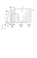
- FIG. 14 is a perspective view of the surface light source device of this embodiment, and corresponds to FIG. 1 of the first embodiment.
- FIG. 15 is a plan view of the surface light source device of the present embodiment, and corresponds to FIG. 2 of the first embodiment.
- the same reference numerals are given to the same components as those in FIG. 1 and FIG.
- the reflection part 31 of the present embodiment is the same as the reflection part 31 of the seventh embodiment.
- the surface light source device 40 of this embodiment is parallel to the first main surface 3a of the light guide 3 and perpendicular to the light propagation direction (y-axis direction), as in the seventh embodiment.
- the configuration of the light source 41 for emitting light having high directivity in the direction (y-axis direction) parallel to the first main surface 3a of the light guide 3 and perpendicular to the light propagation direction is the seventh. Different from the embodiment.
- the light source 41 has a configuration in which a plurality of light emitting units 42 are arranged in a line in a direction (y-axis direction) perpendicular to the light propagation direction.
- the light emitting unit 42 includes an LED 43, a cylindrical lens 44, and a mirror 45.
- the cylindrical lens 44 is a so-called plano-convex lens having one convex surface and the other flat surface. Since light is emitted from the flat surface 44a, the flat surface 44a is hereinafter referred to as a light emitting surface.
- the convex surface 44b has a curved surface that is gently curved and two flat surfaces that are continuous with both ends of the curved surface.
- the curved surface of the convex surface 44b has a curved shape having a focal point S as shown in FIG.
- the cross-sectional shape of the curved surface is a parabolic shape.
- the curved surface is a linear shape. That is, the curved surface of the cylindrical lens 44 is a paraboloid that is curved in the xy plane and not curved in the xy plane.
- a mirror 45 is provided along the curved surface of the cylindrical lens 44.
- the shape of the mirror 45 is a paraboloid reflecting the shape of the curved surface. Therefore, the position of the focal point S of the mirror 45 coincides with the position of the focal point S of the cylindrical lens 44.
- the focal point is indicated by point S in FIG.
- the light exit surface 44a of the cylindrical lens 44 is provided with a groove 46 having a depth sufficient to allow the LED 43 to be inserted therein.
- the cross-sectional shape of the bottom of the groove 46 when the cylindrical lens 44 is cut along the xy plane is rounded into an arc.
- a rod-shaped LED 43 is arranged inside the groove 46.
- the LED 43 is arranged with its light emitting surface facing the mirror 45.
- the LED 43, the mirror 45, and the cylindrical lens 44 are set such that their positional relationship, size, shape, and the like are set so that the focal point S of the mirror 45 and the cylindrical lens 44 is located on the light emitting surface of the LED 43.
- the LED 43 Since the light emitting surface of the LED 43 faces the mirror 45, almost all of the light emitted from the light emitting surface of the LED 43 is directed to the mirror 45, reflected by the mirror 45, and then emitted from the light emitting surface 44a of the cylindrical lens 44.
- the LED 43 is not particularly directional, and a general LED that emits light at a predetermined diffusion angle can be used.
- the light L emitted from the light emitting surface of the LED 43 is directed to the mirror 45 with a predetermined diffusion angle and reflected by the mirror 45. Since the position of the light emitting surface of the LED 43 coincides with the focal point S, the light L emitted from the LED 43 is incident on the mirror 45 at any angle. Travels in a direction parallel to the optical axis. Accordingly, the diffused light immediately after being emitted from the light emitting surface of the LED 43 is reflected by the mirror 45 to be converted into light that is parallelized in the y-axis direction, that is, light that has high directivity in the y-axis direction, and a cylindrical lens. The light exits from the light exit surface 44 a of 44 and enters the light guide 3.
- the light transmitting portion 38 is provided only at the focal point and the vicinity thereof, and only the light passing through the focal point and the vicinity thereof is reflected by the mirror lens 36 as in the first embodiment. Therefore, as described in the first embodiment, light having high directivity in the light propagation direction (x-axis direction) can be obtained by the action of the reflecting portion 31. In this manner, similarly to the first to sixth embodiments, the surface light source device of this embodiment can obtain emitted light with high directivity.
- the light source 41 of this embodiment is provided with the cylindrical lens 44 inside the mirror 45, the cylindrical lens 44 does not necessarily need to be provided and the inside of the mirror 45 may be hollow.
- the ninth embodiment of the present invention will be described below with reference to FIG.
- a display device including the surface light source device of the above embodiment is shown.
- the present embodiment is an example of a liquid crystal display device that includes the surface light source device of the first embodiment as a backlight.
- the liquid crystal display device 48 of this embodiment includes a backlight 49 (surface light source device), a first polarizing plate 50, a liquid crystal panel 51, a second polarizing plate 52, and a viewing angle widening film. 53.
- the liquid crystal panel 51 is schematically illustrated as a single plate. The observer views the display from the upper side of the liquid crystal display device 48 in FIG. 16 in which the viewing angle widening film 53 is arranged. Therefore, in the following description, the side on which the viewing angle widening film 53 is disposed is referred to as a viewing side, and the side on which the backlight 49 is disposed is referred to as a back side.
- the light emitted from the backlight 49 is modulated by the liquid crystal panel 51, and a predetermined image, character, or the like is displayed by the modulated light.
- the angle distribution of the emitted light becomes wider than before entering the viewing angle widening film 53, and the light is widened. Is injected from. Thereby, the observer can visually recognize the display with a wide viewing angle.
- the liquid crystal panel 51 for example, an active matrix transmissive liquid crystal panel can be used.
- the liquid crystal panel is not limited to an active matrix transmissive liquid crystal panel.
- each pixel does not include a switching thin film transistor (Thin Film Transistor, hereinafter abbreviated as TFT).
- TFT Thin Film Transistor
- a simple matrix type liquid crystal panel may be used. Since a well-known general liquid crystal panel can be used for the liquid crystal panel 51, detailed description of a structure is abbreviate
- a viewing angle widening film 53 is disposed on the viewing side of the liquid crystal display device 48.
- the viewing angle widening film 53 includes a base material 54, a plurality of light diffusion portions 55 formed on one surface of the base material 54 (a surface opposite to the viewing side), and a black layer 56 formed on one surface of the base material 54. (Light absorption layer).
- the viewing angle widening film 53 is disposed on the second polarizing plate 52 in a state where the side where the light diffusing portion 55 is provided faces the second polarizing plate 52 and the base 54 side faces the viewing side.
- the base material 54 a base material made of a transparent resin such as a triacetyl cellulose (TAC) film is preferably used.
- the light diffusing portion 55 is made of an organic material having light transmissivity and photosensitivity such as acrylic resin and epoxy resin.
- the light diffusing unit 55 has a circular horizontal cross section (xy cross section).
- the light diffusion part 55 has a small area on the surface on the base material 54 side serving as the light emission end face, and a large area on the surface opposite to the base material 54 serving as the light incident end face, and is opposite to the base material 54 from the base material 54 side.
- the area of the horizontal section gradually increases toward the side.
- the light diffusing portion 55 has a so-called reverse-tapered truncated cone shape when viewed from the base 54 side.
- the light diffusion portion 55 is a portion that contributes to light transmission in the viewing angle widening film 53. That is, the light incident on the light diffusing portion 55 is totally reflected on the tapered side surface of the light diffusing portion 55, guided in a state of being substantially confined inside the light diffusing portion 55, and diffused in all directions It is injected at.
- the black layer 56 is formed in a region other than the formation region of the plurality of light diffusion portions 55 in the surface of the base 54 on the side where the light diffusion portions 55 are formed.
- the black layer 56 is made of an organic material having light absorption and photosensitivity such as a black resist.
- the screen is not displayed in a liquid crystal display device using a conventional backlight having no directivity. Color misregistration occurs when viewed from the front direction and when viewed from the oblique direction.
- the backlight 49 including the surface light source device 1 of the first embodiment having high directivity in the front direction is used. Light is transmitted only through a small angle range. Thereafter, since the light is diffused in all directions by the viewing angle widening film 53, the observer can see a high-quality image with little color shift when viewed from any direction.
- the liquid crystal display device 58 of the present embodiment includes a backlight 49 (surface light source device), a liquid crystal element 59, and a light emitting element 60, as shown in FIG.
- a red subpixel 61R for displaying with red light a green subpixel 61G for displaying with green light, and a blue subpixel 61B for displaying with blue light are arranged adjacent to each other.
- These three sub-pixels 61R, 61G, and 61B constitute one pixel that is a minimum unit that constitutes a display.
- the backlight 49 emits excitation light L1 that excites the phosphor layers 62R, 62G, and 62B of the light emitting element 60.
- the backlight 49 emits ultraviolet light or blue light as the excitation light L1.
- the liquid crystal element 59 modulates the transmittance of the excitation light L1 emitted from the backlight 49 for each of the subpixels 61R, 61G, and 61B. Excitation light L1 modulated by the liquid crystal element 59 is incident on the light-emitting element 60, and the phosphor layers 62R, 62G, and 62B are excited and emitted light is emitted to the outside. Therefore, in the present embodiment, the upper side of the liquid crystal display device 58 shown in FIG.
- the liquid crystal element 59 has a configuration in which a liquid crystal layer 65 is sandwiched between a first transparent substrate 63 and a second transparent substrate 64.
- the second transparent substrate 64 positioned on the front side as viewed from the observer also serves as the substrate of the light emitting element 60.
- a first transparent electrode 66 is formed for each subpixel on the inner surface (the liquid crystal layer 65 side surface) of the first transparent substrate 63, and an alignment film (not shown) is formed so as to cover the first transparent electrode 66. Yes.
- a first polarizing plate 67 is provided on the outer surface of the first transparent substrate 63 (the surface opposite to the liquid crystal layer 65 side).
- the first transparent substrate 63 a substrate made of glass, quartz, plastic, or the like that can transmit excitation light can be used.
- a transparent conductive material such as indium tin oxide (Indium Tin Oxide, hereinafter abbreviated as ITO) is used.
- ITO Indium Tin Oxide
- the first polarizing plate 67 a conventional externally attached polarizing plate can be used.
- the phosphor layer 62 and the first light absorption layer 68 are laminated in this order from the substrate side on the inner surface (the surface on the liquid crystal layer 65 side) of the second transparent substrate 64.
- the phosphor material constituting the phosphor layer 62 has a different emission wavelength band for each subpixel.
- the red subpixel 61R is provided with a phosphor layer 62R made of a phosphor material that absorbs ultraviolet light and emits red light.
- the green subpixel 61G is provided with a phosphor layer 62G made of a phosphor material that absorbs ultraviolet light and emits green light.
- the blue subpixel 61B is provided with a phosphor layer 62B made of a phosphor material that absorbs ultraviolet light and emits blue light.
- the red sub-pixel 61R and the green sub-pixel 61G are made of phosphor materials that absorb blue light and emit red light and green light, respectively.
- the blue sub-pixel 61B is provided with a light diffusing layer that diffuses the blue light, which is the excitation light, without converting the wavelength and emits it to the outside instead of the phosphor layer. It is done.
- a second polarizing plate 69 is formed on the inner surface of the second transparent substrate 64 so as to cover the first light absorption layer 68, and a second transparent electrode 70 and an alignment film (not shown) are formed on the surface of the second polarizing plate 69. ) Are stacked.
- the second polarizing plate 69 is a so-called in-cell polarizing plate that is made using a coating technique or the like in the manufacturing process of the liquid crystal element 59.
- a transparent conductive material such as ITO is used for the second transparent electrode 70.
- a second light absorption layer 71 is formed on the outer surface side of the second transparent substrate 64.
- the first light absorption layer 68 provided on the inner surface of the second transparent substrate 64 is for suppressing a decrease in contrast due to leakage of the excitation light L ⁇ b> 1 from the backlight 49.
- the second light absorption layer 71 provided on the outer surface of the second transparent substrate 64 is for suppressing a decrease in contrast due to external light.
- an ordinary liquid crystal display device has a color shift when viewed from an oblique direction.
- the fluorescence excitation type liquid crystal display device 54 of the present embodiment uses an ultraviolet or blue light surface light source device having high directivity as the backlight 44, and uses the ultraviolet light or blue light as the phosphor layer 58. Color conversion. At this time, the light of each color is isotropically emitted from the phosphor layer 58, so that the observer can see a high-quality image with little color shift when viewed from any direction.
- FIG. 18 is a front view illustrating a schematic configuration of a liquid crystal display device which is a configuration example of the display device.
- the liquid crystal television 73 of this configuration example includes the liquid crystal display device 48 of the ninth embodiment or the liquid crystal display device 58 of the tenth embodiment as a display screen.
- a liquid crystal panel is disposed on the viewer side (front side in FIG. 18), and a backlight (surface light source device) is disposed on the side opposite to the viewer (back side in FIG. 18).
- the liquid crystal television 73 of this configuration example is a high-quality liquid crystal television by including the liquid crystal display devices 48 and 58 of the above embodiment.
- FIG. 19 is a diagram illustrating a schematic configuration of the illumination device. Since the basic configuration of the illuminating device is substantially the same as that of the surface light source device of the first embodiment, the same reference numerals are given to the same components in FIG. 19 as those in FIG. 3 of the first embodiment, and description thereof is omitted.
- the illumination device 75 of this configuration example includes an LED 2, a light guide 3, and a plurality of reflection units 4. That is, the illumination device 75 is the same as the surface light source device 1 of the first embodiment. If the illuminating device 75 is installed with the first main surface of the light guide 3 directed obliquely downward, the light L having high directivity can be emitted obliquely downward of the illuminating device 75.
- the lighting device 75 of the present configuration example is installed near the ceiling of a hall, for example, light with high directivity is emitted downward from the lighting device 75, so that it can be used as a spotlight.
- the shape of the concave mirror constituting the reflecting portion is a paraboloid.
- the shape of the concave mirror that can be used in the above embodiment is not necessarily limited to a paraboloid, and may be a conical curved surface as a concept including a paraboloid.
- a curve indicating the shape of a cross section passing through the apex of the conical curved surface is called a quadratic curve.
- a quadratic curve is a curve obtained from a cross section obtained by cutting a cone at an arbitrary plane.
- the quadratic curve can be expressed by the following equations (1) and (2).
- the shape of the quadratic curve changes depending on the value of the conic coefficient k in the equations (1) and (2).
- a concave mirror having a cross-sectional shape of these quadratic curves can be used.
- attains should just be a conical curved surface at least, the area
- the aspect of the present invention can be used for various display devices such as a liquid crystal display device, a surface light source device used for this type of display device, or various illumination devices.
Landscapes
- Physics & Mathematics (AREA)
- Nonlinear Science (AREA)
- General Physics & Mathematics (AREA)
- Optics & Photonics (AREA)
- Mathematical Physics (AREA)
- Chemical & Material Sciences (AREA)
- Crystallography & Structural Chemistry (AREA)
- Planar Illumination Modules (AREA)
- Liquid Crystal (AREA)
Abstract
L'invention porte sur un dispositif de source de lumière de surface, lequel dispositif comporte une source de lumière, un corps de guidage de lumière et une section réfléchissante. Le corps de guidage de lumière comporte une première surface principale et une seconde surface principale, permet à une lumière émise à partir de la source de lumière d'entrer dans le corps de guidage de lumière, et provoque la réflexion totale de la lumière entre la première surface principale et la seconde surface principale de façon à permettre à la lumière de se propager à l'intérieur du corps de guidage de lumière. La section réfléchissante réfléchit une partie de la lumière se propageant à l'intérieur du corps de guidage de lumière, la partie de la lumière étant émise à partir de la seconde surface principale, de façon à changer la direction de déplacement de la partie de la lumière, et provoque à nouveau l'entrée de la partie de la lumière dans le corps de guidage de lumière et sa sortie à partir de la première surface principale. La section réfléchissante comporte un miroir concave et une section perméable à la lumière. Le miroir concave comporte une surface réfléchissante faisant face à la seconde surface principale du corps de guidage de lumière, et est formé sous une forme ayant un point focal à l'intérieur d'un plan qui est parallèle à la direction de propagation de la lumière, et qui est perpendiculaire à la seconde surface principale. La section perméable à la lumière est en contact avec la seconde surface principale du corps de guidage de lumière, et est disposée en une position comprenant le point focal du miroir concave. La section perméable à la lumière permet à une partie de la lumière se propageant à l'intérieur du corps de guidage de lumière et atteignant la seconde surface principale et, à la partie de la lumière passant à travers le point focal ou au voisinage du point focal, de traverser la section perméable à la lumière et de sortir vers la surface réfléchissante du miroir concave.
Applications Claiming Priority (2)
| Application Number | Priority Date | Filing Date | Title |
|---|---|---|---|
| JP2011095978A JP2014135116A (ja) | 2011-04-22 | 2011-04-22 | 面光源装置およびその製造方法、表示装置、照明装置 |
| JP2011-095978 | 2011-04-22 |
Publications (1)
| Publication Number | Publication Date |
|---|---|
| WO2012144514A1 true WO2012144514A1 (fr) | 2012-10-26 |
Family
ID=47041620
Family Applications (1)
| Application Number | Title | Priority Date | Filing Date |
|---|---|---|---|
| PCT/JP2012/060429 Ceased WO2012144514A1 (fr) | 2011-04-22 | 2012-04-18 | Dispositif de source de lumière de surface, procédé pour sa fabrication, dispositif d'affichage le comportant, et dispositif d'éclairage le comportant |
Country Status (2)
| Country | Link |
|---|---|
| JP (1) | JP2014135116A (fr) |
| WO (1) | WO2012144514A1 (fr) |
Citations (11)
| Publication number | Priority date | Publication date | Assignee | Title |
|---|---|---|---|---|
| JPH0579537U (ja) * | 1992-03-25 | 1993-10-29 | 株式会社エンプラス | 面光源装置 |
| JP2004047278A (ja) * | 2002-07-12 | 2004-02-12 | Minolta Co Ltd | 照明装置 |
| JP2004119354A (ja) * | 2002-09-30 | 2004-04-15 | Casio Comput Co Ltd | 面光源装置 |
| JP2004171966A (ja) * | 2002-11-21 | 2004-06-17 | Matsushita Electric Ind Co Ltd | 面照明装置 |
| JP2005038822A (ja) * | 2003-06-26 | 2005-02-10 | Sharp Corp | フラットパネルディスプレイ用照明装置、および、発光ランプ |
| JP2006093104A (ja) * | 2004-08-25 | 2006-04-06 | Seiko Instruments Inc | 照明装置およびそれを用いた表示装置 |
| JP2006156368A (ja) * | 2004-11-02 | 2006-06-15 | Hisashi Kojima | 導光板及びバックライト装置 |
| JP2007234385A (ja) * | 2006-02-28 | 2007-09-13 | Yamaha Corp | バックライト装置 |
| JP2008027757A (ja) * | 2006-07-21 | 2008-02-07 | Trion:Kk | 光学用板体並びにこれを用いた導光板及び反射板 |
| WO2010077367A2 (fr) * | 2009-01-02 | 2010-07-08 | Brian Edward Richardson | Système optique pour un guide lumineux ayant une sortie commandée |
| JP2010177130A (ja) * | 2009-01-30 | 2010-08-12 | Keiwa Inc | 導光シート及びこれを用いたバックライトユニット |
-
2011
- 2011-04-22 JP JP2011095978A patent/JP2014135116A/ja not_active Withdrawn
-
2012
- 2012-04-18 WO PCT/JP2012/060429 patent/WO2012144514A1/fr not_active Ceased
Patent Citations (11)
| Publication number | Priority date | Publication date | Assignee | Title |
|---|---|---|---|---|
| JPH0579537U (ja) * | 1992-03-25 | 1993-10-29 | 株式会社エンプラス | 面光源装置 |
| JP2004047278A (ja) * | 2002-07-12 | 2004-02-12 | Minolta Co Ltd | 照明装置 |
| JP2004119354A (ja) * | 2002-09-30 | 2004-04-15 | Casio Comput Co Ltd | 面光源装置 |
| JP2004171966A (ja) * | 2002-11-21 | 2004-06-17 | Matsushita Electric Ind Co Ltd | 面照明装置 |
| JP2005038822A (ja) * | 2003-06-26 | 2005-02-10 | Sharp Corp | フラットパネルディスプレイ用照明装置、および、発光ランプ |
| JP2006093104A (ja) * | 2004-08-25 | 2006-04-06 | Seiko Instruments Inc | 照明装置およびそれを用いた表示装置 |
| JP2006156368A (ja) * | 2004-11-02 | 2006-06-15 | Hisashi Kojima | 導光板及びバックライト装置 |
| JP2007234385A (ja) * | 2006-02-28 | 2007-09-13 | Yamaha Corp | バックライト装置 |
| JP2008027757A (ja) * | 2006-07-21 | 2008-02-07 | Trion:Kk | 光学用板体並びにこれを用いた導光板及び反射板 |
| WO2010077367A2 (fr) * | 2009-01-02 | 2010-07-08 | Brian Edward Richardson | Système optique pour un guide lumineux ayant une sortie commandée |
| JP2010177130A (ja) * | 2009-01-30 | 2010-08-12 | Keiwa Inc | 導光シート及びこれを用いたバックライトユニット |
Also Published As
| Publication number | Publication date |
|---|---|
| JP2014135116A (ja) | 2014-07-24 |
Similar Documents
| Publication | Publication Date | Title |
|---|---|---|
| JP6715829B2 (ja) | 直視型ディスプレイ装置、および直視型ディスプレイ装置用の照明ユニット | |
| KR101699058B1 (ko) | 백라이트 어셈블리 및 이를 갖는 표시장치 | |
| TWI761599B (zh) | 光柵耦合光導件、顯示系統、以及使用光學聚光的方法 | |
| JP4856261B2 (ja) | 光をコリメートする導光体、導光体のコリメーション改善方法、バックライト、及び表示装置 | |
| CN101542365B (zh) | 显示装置 | |
| KR20150026044A (ko) | 광학 시트, 이를 포함하는 백라이트 유닛 및 표시장치 | |
| TW201231875A (en) | Surface light source device and liquid crystal display device | |
| JP2011014520A (ja) | 照明装置及び表示装置 | |
| KR20060057857A (ko) | 프리즘 시트 및 이를 채용한 백라이트 유니트 | |
| JP2014235896A (ja) | 面光源装置、表示装置および照明装置 | |
| JP7130921B2 (ja) | 光学構造体、表示装置 | |
| CN113495386B (zh) | 照明装置及显示装置 | |
| WO2014041828A1 (fr) | Dispositif de source de lumière plan et dispositif d'affichage qui utilise ce dernier | |
| US20150146132A1 (en) | Surface light source device, display device, and lighting device | |
| TWI439735B (zh) | 柱狀透鏡陣列之裝置及其背光模組 | |
| WO2012161212A1 (fr) | Dispositif de source de lumière plan et procédé de fabrication pour celui-ci, dispositif d'affichage et dispositif d'éclairage | |
| JP2014135120A (ja) | 面光源装置、表示装置および照明装置 | |
| JP2012523580A (ja) | 曲面スリット付き光ガイド曲がり | |
| CN110632786A (zh) | 显示面板及显示装置 | |
| WO2013081038A1 (fr) | Dispositif de source de lumière, dispositif de source de lumière de surface, dispositif d'affichage et dispositif d'éclairage | |
| CN104678650B (zh) | 背光模块 | |
| CN103235446A (zh) | 一种用于液晶显示器的背光模组 | |
| WO2013035660A1 (fr) | Dispositif de source de lumière de surface, dispositif d'affichage et dispositif d'éclairage | |
| CN101341438A (zh) | 显示装置和液晶显示装置 | |
| JP2014154332A (ja) | 面光源装置 |
Legal Events
| Date | Code | Title | Description |
|---|---|---|---|
| 121 | Ep: the epo has been informed by wipo that ep was designated in this application |
Ref document number: 12774183 Country of ref document: EP Kind code of ref document: A1 |
|
| NENP | Non-entry into the national phase |
Ref country code: DE |
|
| 122 | Ep: pct application non-entry in european phase |
Ref document number: 12774183 Country of ref document: EP Kind code of ref document: A1 |
|
| NENP | Non-entry into the national phase |
Ref country code: JP |