WO2012144581A1 - Système de commande du fonctionnement destiné à un dispositif de source de froid - Google Patents
Système de commande du fonctionnement destiné à un dispositif de source de froid Download PDFInfo
- Publication number
- WO2012144581A1 WO2012144581A1 PCT/JP2012/060665 JP2012060665W WO2012144581A1 WO 2012144581 A1 WO2012144581 A1 WO 2012144581A1 JP 2012060665 W JP2012060665 W JP 2012060665W WO 2012144581 A1 WO2012144581 A1 WO 2012144581A1
- Authority
- WO
- WIPO (PCT)
- Prior art keywords
- ratio
- cooling
- flow rate
- cooling tower
- refrigerator
- Prior art date
- Legal status (The legal status is an assumption and is not a legal conclusion. Google has not performed a legal analysis and makes no representation as to the accuracy of the status listed.)
- Ceased
Links
Images


Classifications
-
- F—MECHANICAL ENGINEERING; LIGHTING; HEATING; WEAPONS; BLASTING
- F24—HEATING; RANGES; VENTILATING
- F24F—AIR-CONDITIONING; AIR-HUMIDIFICATION; VENTILATION; USE OF AIR CURRENTS FOR SCREENING
- F24F5/00—Air-conditioning systems or apparatus not covered by F24F1/00 or F24F3/00, e.g. using solar heat or combined with household units such as an oven or water heater
- F24F5/0003—Exclusively-fluid systems
-
- F—MECHANICAL ENGINEERING; LIGHTING; HEATING; WEAPONS; BLASTING
- F28—HEAT EXCHANGE IN GENERAL
- F28C—HEAT-EXCHANGE APPARATUS, NOT PROVIDED FOR IN ANOTHER SUBCLASS, IN WHICH THE HEAT-EXCHANGE MEDIA COME INTO DIRECT CONTACT WITHOUT CHEMICAL INTERACTION
- F28C1/00—Direct-contact trickle coolers, e.g. cooling towers
- F28C2001/006—Systems comprising cooling towers, e.g. for recooling a cooling medium
Definitions
- the present invention relates to an operation control system for a cold heat source apparatus, and more particularly, to an operation control system for a cold heat source apparatus that can perform an energy saving operation of the cold heat source apparatus.
- the low temperature side refrigerator is set to the rated operation, and the high temperature side refrigerator is set to the partial cooling load operation in order to process the remaining cooling load.
- the energy-saving operation of the refrigerator according to the cooling load is not performed. Further, energy-saving operation of the cold water pump, the cooling water pump, and the cooling tower fan according to the state of the outside air (for example, the wet bulb temperature) is not performed.
- the present invention has been made in view of such circumstances, and provides an operation control system for a cold heat source apparatus that can save energy in the entire refrigerator-type cold heat source apparatus according to the cooling load and the state of the outside air. For the purpose.
- an operation control system for a cold heat source apparatus comprises a plurality of heat pump refrigerators arranged in series in a cold water pipe for supplying cold water to an external load device.
- a chilled water pump for cooling the chilled water recirculated from the external load device with the evaporator of the refrigerator and supplying the chilled water to the external load device again; and supplying the cooling water to the condenser of the refrigerator via a cooling water pipe
- the cooling water pump and the cooling tower fan are provided for each of the plurality of refrigerators.
- the operation control system has an actual refrigeration load with respect to a total value of the wet bulb temperature of outside air taken into the cooling tower by the cooling tower fan and the set refrigeration capacity of each of the plurality of refrigerators.
- the COP of the whole cold heat source apparatus is maximized with the flow rate ratio of the cooling water pump of each refrigerator, the air volume ratio of the cooling tower fan, and the load distribution ratio for distributing the refrigeration load ratio to each of the refrigerators as variables.
- the operation control system of the cold heat source apparatus according to claim 1 is a case where a cooling water pump and a cooling tower fan are provided for each of a plurality of refrigerators.
- control means controls the chilled water pump of each refrigerator based on the chilled water flow rate ratio, the flow rate ratio of the cooling water pump of each chiller, the flow rate ratio of the cooling tower fan, and the refrigeration load ratio to each chiller.
- the optimal flow rate ratio, the optimal air flow rate ratio, and the optimal load distribution ratio for maximizing the COP of the entire cold heat source device are simulated by a simulator using the load distribution ratio for distributing
- the cooling water temperature at the outlet of each refrigerator is controlled based on the ratio, and the cooling water pump and cooling tower fan of each cooling tower are controlled based on the optimum flow rate ratio and optimum air flow ratio.
- COP is an abbreviation for Coefficient Of Performance, and is also called a performance coefficient.
- the set refrigeration capacity of the refrigerator refers to the rated refrigeration capacity of the refrigerator or the refrigeration capacity arbitrarily set by the user.
- the acquisition unit causes the wet bulb temperature of the outside air taken into the cooling tower by the cooling tower fan, and the set refrigeration capacity of each of the plurality of refrigerators arranged in series.
- a refrigeration load ratio that represents an actual refrigeration load with respect to the total value of, and a chilled water flow ratio that represents an actual chilled water flow rate with respect to the rated chilled water flow rate of chilled water.
- the COP of the whole cold heat source apparatus is first determined by the simulator using the flow rate ratio of the cooling water pump of each refrigerator, the air volume ratio of the cooling tower fan, and the load distribution ratio for distributing the refrigeration load ratio to each refrigerator as variables. Simulate the optimal flow ratio, optimal airflow ratio, and optimal load distribution ratio to maximize. Accordingly, in order to maximize the COP of the entire cold heat source device at the outside air wet bulb temperature, the refrigeration load ratio, and the chilled water flow rate ratio acquired by the acquisition means, each chiller and the cooling water corresponding to each chiller It is possible to determine at what ratio the pump and cooling tower fan are shared.
- the control means controls the chilled water pump based on the chilled water flow rate ratio, controls the outlet chilled water temperature of each refrigerator based on the optimum load distribution ratio, and controls each cooling tower based on the optimum flow rate ratio and the optimum air volume ratio. Control the cooling water pump and cooling tower fan.
- the operation control system can perform operation control so that the power consumption of the entire refrigerator-type cold heat source apparatus is minimized according to the cooling load and the state of the outside air.
- the simulator includes an optimal load distribution ratio that maximizes the COP according to the refrigeration load ratio and the outside air wet bulb temperature, or the outlet chilled water temperature, the optimal flow rate ratio, and the optimal air flow ratio of each refrigerator.
- the simulator reads the optimal load distribution ratio and the optimal flow rate from the control table. It is preferable to select the ratio and the optimum air volume ratio.
- the simulator needs to repeat the calculation by changing the variable load distribution ratio, flow rate ratio, and air volume ratio until the COP becomes maximum.
- the optimal load distribution ratio, optimal flow ratio, and optimal air flow ratio the acquired outdoor wet bulb temperature, refrigeration load ratio, and chilled water flow ratio are assumed as preconditions. Must-have. As a result, the computation load for simulation increases, leading to an increase in power consumption of the entire operation control system.
- the optimum load distribution ratio, optimum flow rate ratio and optimum air volume ratio are determined from the control table according to the outside wet bulb temperature and the refrigeration load ratio acquired by the acquisition means. Since it only has to be selected, the simulation load can be significantly reduced.
- the operation control system varies the first inverter that varies the rotation speed of the chilled water pump, the second inverter that varies the rotation speed of the cooling water pump, and the rotation speed of the cooling tower fan.
- a third inverter, and the control means converts the chilled water flow rate ratio, the optimum flow rate ratio, and the air volume ratio into inverter frequencies and outputs the inverter frequency to the first to third inverters. It is preferable that inverters control the rotational speeds of the pump, the cooling water pump, and the cooling tower fan.
- the control means stops the operation of the refrigerator in which the allocation of the optimum load distribution ratio is 0% by the simulator among the plurality of refrigerators and corresponds to the stopped refrigerator It is preferable to stop the cooling water pump and the cooling tower fan. Thereby, further energy saving operation can be achieved.
- an operation control system for a cold heat source apparatus comprises a plurality of heat pump refrigerators arranged in series in a cold water pipe for supplying cold water to an external load device.
- a chilled water pump for cooling the chilled water recirculated from the external load device with the evaporator of the refrigerator and supplying the chilled water to the external load device again; and supplying the cooling water to the condenser of the refrigerator via a cooling water pipe
- the cooling system has at least one cooling tower for the plurality of refrigerators, The cooling water cooled by the cooling tower fan of the cooling tower is distributed to each of the plurality of refrigerators by each cooling water pump, and the operation control system is configured to supply outside air to be taken into the cooling tower by the cooling tower fan.
- the operation control system for a cold heat source apparatus has at least one cooling tower for a plurality of refrigerators, and each cooling water pump supplies cooling water cooled by a cooling tower fan of the cooling tower to the plurality of refrigerators. This is the case of distributing with.
- the simulation by the simulator in this case can be performed in the same manner as in claim 1 by substituting “cooling tower fan air volume ratio” in claim 1 with “cooling tower fan air volume”.
- an operation control system for a cold heat source apparatus comprises a plurality of heat pump refrigerators arranged in series in a cold water pipe for supplying cold water to an external load device.
- a chilled water pump for cooling the chilled water recirculated from the external load device with the evaporator of the refrigerator and supplying the chilled water to the external load device again; and supplying the cooling water to the condenser of the refrigerator via a cooling water pipe
- the cooling system has at least one cooling tower for the plurality of refrigerators, The cooling water cooled by the cooling tower fan of the cooling tower is sequentially supplied from the high temperature side refrigerator to the low temperature side refrigerator of the plurality of refrigerators with a single cooling water pump, and the operation control system includes:
- the cooling tower Refrigeration load ratio representing the actual refrigeration load with respect to the total value of the set refrigeration capacity of each
- the operation control system for a cold heat source apparatus has at least one cooling tower for a plurality of refrigerators, and the cooling water cooled by the cooling tower fan of the cooling tower is a high temperature side refrigerator of the plurality of refrigerators.
- the simulator simulation in this case replaces the “cooling tower fan air volume ratio” in claim 1 with “cooling tower fan air volume”, and the “cooling water pump flow ratio” in claim 1 changes to “cooling water pump air volume ratio”. By replacing with “flow rate”, the same operation as in claim 1 can be performed.
- the cooling tower is not limited to having a plurality of units as long as it has a capacity sufficient to cover the cooling capacity of the plurality of refrigerators. I just need it.
- the cold heat source device includes a bypass pipe that bypasses the refrigerator
- the operation control system includes an on-off valve that opens and closes the bypass pipe
- the control means performs the operation. It is preferable to open the on-off valve of the bypass pipe of the stopped refrigerator.
- the present invention it is possible to control the operation so that the power consumption of the entire refrigerator-type cold heat source apparatus is reduced according to the cooling load and the state of the outside air. It is possible to provide an operation control system for a cold heat source apparatus.
- control table which tabulated the optimal airflow ratio with respect to the refrigeration load ratio and wet-bulb temperature of the high temperature side cooling tower fan. It is an example of the control table which tabulated the optimal exit cold water temperature with respect to the refrigerating load ratio and wet-bulb temperature of a high temperature side refrigerator. It is another example of composition of the cold-heat source device of this embodiment, and its operation control system. It is the further another structural example of the cold-heat-source apparatus of this embodiment, and its operation control system.
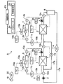
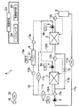
- FIG. 1 is a configuration diagram of a cold heat source apparatus A and its operation control system according to the present embodiment.
- a cold heat source device A is a device that supplies cold to an external load device B (for example, an air conditioner) that uses cold, and includes a high temperature side refrigerator 1 and a low temperature side refrigerator.
- an external load device B for example, an air conditioner
- 2 and 2 refrigerators are arranged in series. That is, while supplying cold water to the external load device B, the two refrigerators 1 and 2 are arranged in series in the cold water pipe 17a through which the cold water heated by the external load device B flows back.
- the high temperature side refrigerator 1 means a refrigerator through which cold water recirculated from the external load device B first passes, and the low temperature side refrigerator 2 is intended for cold water cooled halfway by the high temperature side refrigerator 1.
- the refrigerator which cools to temperature and supplies to the external load apparatus B is meant.
- the cold heat source apparatus A is described as including two refrigerators 1 and 2, but the number of refrigerators included in the cold heat source apparatus A may be two or more.
- the refrigerators 1 and 2 are heat pump type refrigerators, and the internal structure thereof is not particularly shown, but mainly has an evaporator and a condenser, and a refrigerant flows between them.
- the refrigerators 1 and 2 cool the cold water flowing in the cold water pipe 17a by evaporating the refrigerant liquid with the evaporator, cool the evaporated refrigerant gas with the condenser to condense and liquefy the refrigerant liquid again, It is supposed to circulate.
- a heat pump type refrigerator a turbo refrigerator, an absorption refrigerator, etc. can be used, for example.
- the cold water pipe 17 a includes a cold water pump 3, a cold water flow meter 11 a, a first thermometer 12 a for measuring the cold water temperature on the inlet side of the high temperature side refrigerator 1, and the high temperature side refrigerator 1.
- the 2nd thermometer 12b which measures the chilled water temperature of the exit side of this, and the 3rd thermometer 12c which measures the chilled water temperature of the exit side of the low temperature side refrigerator 2 are provided.
- the cold water temperature on the inlet side of the low temperature side refrigerator 2 is the same as the outlet temperature of the high temperature side refrigerator 1.
- the cold water whose temperature has been increased by the external load device B is conveyed through the cold water pipe 17 a by the cold water pump 3 and is cooled to a predetermined temperature through the high temperature side refrigerator 1. Thereafter, the chilled water cooled to a predetermined temperature passes through the low temperature side refrigerator 2 and is cooled to the target temperature and supplied to the external load device B.
- the cold water flow meter 11a and the first to third thermometers 12a to 12c are connected to the control means 23 described later by a cable, and the measured values are input to the control means 23.
- the description of various cables connected to the control means 23 is omitted so as not to make the diagram complicated, and the same applies to other FIGS. 2 to 4, 9, and 10 described later.
- an inverter 8 is connected to a drive motor (not shown) of the cold water pump 3, and the inverter 8 is connected to a control command unit 25 of the control means 23.
- the control command part 25 carries out inverter control of the rotational speed of the drive motor of the cold water pump 3 according to the cold water flow rate ratio L rate (%).
- the cold water flow rate ratio L rate (%) refers to the actual cold water flow rate with respect to the rated cold water flow rate of the cold heat source apparatus A.
- the high-temperature side refrigerator 1 is provided with a bypass pipe 17b that connects the inlet side and the outlet side, and an on-off valve 15 is provided in the bypass pipe 17b.
- the on-off valve 15 is connected to the control command unit 25 of the control means 23 by a cable.
- the control command part 25 can flow the cold water which flows through the cold water piping 17a to both the high temperature side refrigerator 1 and the low temperature side refrigerator 2 by closing the on-off valve 15.
- the control command unit 25 opens the on-off valve 15, the cold water flowing through the cold water pipe 17 a can bypass the high temperature side refrigerator 1 and flow only to the low temperature side refrigerator 2.
- the two refrigerators 1 and 2 on the high temperature side and the low temperature side are provided with cooling towers 6 and 7, respectively, and are provided between the condensers of the refrigerators 1 and 2 and the cooling towers 6 and 7, respectively.
- the cooling water circulates in the cooling water pipes 18a and 18b, which are circulation channels.
- the cooling water pipes 18a and 18b are indicated by a one-dot chain line so as to be easily distinguished from the cooling water pipe 17a.
- the configuration of the cooling towers 6 and 7 is not particularly illustrated, the cooling towers 6 and 7 mainly include cooling tower fans 21a and 21b, a water spray pipe (not shown), and a cooling water storage tank (not shown), and are cooled by the cooling tower fans 21a and 21b.
- the outside water taken into the towers 6 and 7 and the cooling water sprayed from the water spray pipes are brought into contact with each other in a counter current, whereby the cooling water is cooled.
- the cooling water cooled by the outside air in the cooling towers 6 and 7 is transported through the cooling water pipes 18a and 18b by the cooling water pumps 4 and 5 and supplied to the condensers of the refrigerators 1 and 2, and the evaporator Cools the refrigerant circulating between the air and the condenser.
- Inverter 10a, 10b is connected to the drive motor (not shown) of cooling tower fan 21a, 21b, and inverter 10a, 10b is connected to the control command part 25 of the control means 23 by the cable.
- the control command unit 25 performs inverter control on the rotational speed of the drive motors of the cooling tower fans 21 a and 21 b based on the optimum air flow ratio (described later) calculated by the simulator 24 of the control means 23.
- the high temperature side cooling water pipe 18a means that provided for the high temperature side refrigerator 1, and the low temperature side cooling water pipe 18b is provided for the low temperature side refrigerator 2. The same applies to the devices and members described below.
- the cold heat source apparatus A is provided with an outside air thermometer 19 and an outside air hygrometer 20 for measuring the temperature and humidity of the outside air taken into the cooling towers 6 and 7, and these measuring instruments are connected to the control means 23 by cables.
- the cooling water pipes 18a and 18b on the high temperature side and the low temperature side respectively include cooling water flow meters 11b and 11c, inlet thermometers 13a and 14a for measuring the cooling water temperature on the inlet side of the cooling towers 6 and 7, and a cooling tower. 6 and 7 are provided with outlet thermometers 13b and 14b for measuring the coolant temperature on the outlet side, and these measuring instruments are connected to the control means 23 by cables.
- inverters 9a and 9b are connected to the cooling water pumps 4 and 5, and the inverters 9a and 9b are connected to the control command unit 25 of the control means 23 by cables.
- the control command unit 25 performs inverter control on the rotational speed of the drive motor of the cooling water pumps 4 and 5 based on the optimum flow rate ratio (described later) calculated by the simulator 24 of the control means 23.
- the outlet thermometers 13b and 14b of the cooling towers 6 and 7 and the inverters 10a and 10b for controlling the cooling tower fans 21a and 21b are connected to the first temperature indicating controllers 16a and 16b with cables (not shown). Connected. Then, the first temperature indicating controllers 16a and 16b use the optimum flow rate ratio commanded from the control command unit 25 to the inverters 10a and 10b so that the coolant temperature of the outlet thermometers 13b and 14b becomes a predetermined temperature. The rotational speed of the drive motor for the cooling tower fans 21a and 21b is controlled.
- the inlet thermometers 13a and 14a of the cooling towers 6 and 7 and the inverters 9a and 9b that perform inverter control of the cooling water pumps 4 and 5 include a second temperature indicating controller 16c. , 16d are connected by cables (not shown). Then, the second temperature indicating controllers 16c and 16d use the optimum air volume ratio commanded from the control command unit 25 to the inverters 9a and 9b so that the cooling water temperature of the inlet thermometers 13a and 14a becomes a predetermined temperature.
- the rotational speed of the drive motor for the cooling water pumps 4 and 5 is controlled.
- PID control can be adopted, but it is not limited to PID control.
- FIG. 1 shows the most preferable mode as the configuration of the cold heat source apparatus A
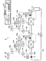
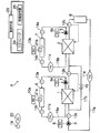
- a mode in which the bypass pipe 17b and the on-off valve 15 are not provided as shown in FIG. 2 may be used, and the temperature indicating controller 16a as shown in FIG. A mode in which ⁇ 16d is not provided is also possible.
- the bypass pipe 17b, the on-off valve 15, and the temperature indicating controllers 16a to 16d may not be provided.
- the chilled water flow meter 11a measures the chilled water flow rate L flowing through the chilled water pipe 17a
- the first to third thermometers 12a to 12c measure the inlet chilled water temperature T1 in of the high temperature side refrigerator 1 and the outlet chilled water of the high temperature side refrigerator 1.
- the temperature T1 out (the inlet cold water temperature T2 in of the low temperature side refrigerator 2) and the outlet cold water temperature T2 out of the low temperature side refrigerator 2 are measured.
- the flow rate of the cooling water flowing through the cooling water pipes 18a and 18b on the high temperature side and the low temperature side is measured by the cooling water flow meters 11b and 11c
- the cooling tower 6 is formed by the inlet thermometers 13a and 14a and the outlet thermometers 13b and 14b.
- the outside air temperature meter 19 measures the outside air temperature Ta
- the outside air hygrometer 20 measures the outside air humidity RH.
- the measurement values measured by these measuring instruments are input to the control means 23, and the refrigeration load ratio Q (%), the outdoor wet bulb temperature TWB (° C.), and the cold water flow rate ratio L rate (%) are calculated.
- the refrigeration load ratio Q (%) is the ratio (%) of the actual cooling load to the total value of the set refrigeration capacities RT cap1 and RT cap2 of the two refrigerators 1 and 2, and the following formula (1 ).
- the denominator “60 * 1000” is a coefficient for converting (L / min) to (m 3 / sec).
- the set refrigeration capacity is a value described in the specification by the refrigerator manufacturer and is stored in the control means 23 in advance.
- the chilled water flow rate ratio L rate (%) is obtained using the calculated refrigeration load ratio Q (%).
- the cold water flow rate ratio L rate (%) is as described above, and is calculated by the following equation (2).
- the outside air wet bulb temperature TWB is calculated from the outside air temperature Ta and the outside air humidity RH using a known formula.
- the control means 23 controls the chilled water pumps 3 of the refrigerators 1 and 2 based on the chilled water flow rate ratio L rate , the flow rate ratios of the cooling water pumps 4 and 5 of the chillers 1 and 2, and the cooling tower fan 21a. , 21b and the load distribution ratio that distributes the refrigeration load ratio Q to each of the refrigerators 1 and 2 as variables, the optimal flow rate for maximizing the COP (Coefficient Of Performance) of the entire cold heat source apparatus A
- the simulator 24 simulates the ratio, the optimum air flow ratio, and the optimum load distribution ratio, and controls the outlet chilled water temperatures T1 out and T2 out of the refrigerators 1 and 2 based on the optimum load distribution ratio obtained by the simulator 24.
- the cooling water pumps 4 and 5 and the cooling tower fans 21a and 21b of the cooling towers 6 and 7 are controlled based on the optimum flow rate ratio and the optimum air volume ratio.
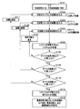
- FIG. 5 shows the simulation steps performed by the simulator 24.
- the refrigeration load ratio Q (%) calculated by the control means 23 and the outdoor wet bulb temperature TWB are input to the simulator 24 (step S101), the flow rate ratio of the cooling water pumps 4 and 5, and the cooling tower.
- the air volume ratio of the fans 21a and 21b is input as an arbitrary constant (giving an arbitrary fixed value) (steps S102 and S103).
- the flow rate ratio and the air volume ratio are not extreme ratios, but ratios that are considered appropriate from the operating ranges of the cooling water pumps 4 and 5 and the cooling tower fans 21a and 21b, for example, 50%: 50%. It is preferable to set to.
- the cold water flow rate ratio L rate (%) is a value that is uniquely determined by the refrigeration load ratio Q (%), as can be seen from the above equation (2), the operation control of the cold heat source apparatus A is performed with the refrigeration load ratio Q ( %) Is used as a representative factor, and the chilled water flow ratio L rate (%) is used to calculate the power consumption of the chilled water pump 3.
- the simulator 24 inputs an arbitrary load distribution ratio using the load distribution ratio for distributing the refrigeration load ratio Q (%) to the high temperature side refrigerator 1 and the low temperature side refrigerator 2 as a variable (step S104).
- the simulator 24 calculates the COP of the entire cold heat source apparatus A (step S105).
- the calculation of COP first calculates the power consumption of the refrigerators 1 and 2 on the high temperature side and the low temperature side, the cold water pump 3, the cooling water pumps 4 and 5, and the cooling tower fans 21a and 21b. That is, the power consumption W 1 and W 2 of the refrigerators 1 and 2 is calculated by the refrigerator manufacturer corresponding to the chilled water temperature data and the refrigerator cooling load data of the refrigerators 1 and 2 from the refrigerator manufacturer. The COP of the refrigerator is estimated based on these data, and the power consumption is calculated by the following equation (3).
- the cold water temperature data at the inlets of the refrigerators 1 and 2 are measured by the first to third thermometers 12a to 12c.
- the cooling load data of the refrigerator 1 and 2, the cold water flow meters 11a, the temperature difference between the first thermometer 12a and the third thermometer 12c, is calculated from the specific heat C p of water.
- the power consumption W of the chilled water pump 3, the cooling water pumps 4 and 5, and the cooling tower fans 21a and 21b is set to f as the rotational frequency of the driving motor that drives these devices.
- rated power consumption for example, power consumption when the commercial power supply frequency is 50 Hz or 60 Hz
- W 0 it can be calculated by the following equation (4).
- Equation (4) the motor efficiency was set to 0.9.
- the system power consumption Wsys which is the power consumption of the entire cooling heat source apparatus A
- the system COP which is the COP of the entire cooling heat source apparatus A
- Step S105 Power consumption of the cooling tower fan 21a on the high temperature side W fan2 ... power consumption (kW) of the cooling tower fan 21b on the low temperature side
- the load distribution ratio is changed until the COP reaches the maximum (see Step S106, No, Step S107), and the calculation in Step S105 is repeated.
- the flow rate ratio of the cooling water pumps 4 and 5 on the high temperature side and the low temperature side and the air flow ratio of the cooling tower fans 21a and 21b are fixed at a certain value, the optimum load distribution that maximizes the COP of the cold heat source apparatus A is achieved.
- the ratio is determined (see step S106 / Yes).
- the simulator 24 changes the air volume ratio (see Step S108, No, Step S109), and similarly determines the optimum load distribution ratio that maximizes the COP of the cold heat source apparatus A at the flow rate ratio and the air volume ratio. (See steps S104 to S108). Furthermore, the simulator 24 changes the flow rate ratio (see step S110 ⁇ No, step S111), and similarly, obtains the optimum load distribution ratio that maximizes the COP of the cold heat source apparatus A at the flow rate ratio and the air flow ratio (see FIG. (See steps S103 to S110).
- the simulator 24 calculates the COP for the combination of the flow rate ratio of the cooling water pumps 4 and 5, the air flow ratio of the cooling tower fans 21a and 21b, and the load distribution ratio of each of the refrigerators 1 and 2, and the COP is maximized.
- a combination of the flow rate ratio of the cooling water pumps 4 and 5, the air flow ratio of the cooling tower fans 21a and 21b, and the load distribution ratio of each of the refrigerators 1 and 2 is selected (step S112).
- the simulator 24 converts the flow rate ratio and the air flow ratio when the COP is maximum into the inverter frequency as the optimal flow ratio and the optimal air flow ratio, and at the high temperature side corresponding to the optimal load distribution ratio when the COP is maximum.
- the outlet cold water temperature T1 out of the refrigerator 1 is calculated (step S113).
- the optimal exit cold water temperature corresponding to an optimal load distribution ratio should just be the high temperature side refrigerator 1.
- FIG. when there are three or more refrigerators, the optimum outlet cold water temperature is calculated for the refrigerators other than the refrigerator at the most downstream position in the cold water flow direction.
- the simulator 24 sends the inverter frequency obtained by converting the optimum flow rate ratio and the optimum air volume ratio and the optimum outlet chilled water temperature to the control command unit 25.
- the control command unit 25 performs inverter control of the chilled water pump 3 based on the chilled water flow rate ratio, controls the high temperature side refrigerator 1 based on the optimum outlet chilled water temperature obtained by the simulator 24, and optimizes the flow rate ratio and the optimum air volume.
- the high temperature side and low temperature side cooling water pumps 4 and 5 and the cooling tower fans 21a and 21b are inverter controlled based on the inverter frequency in which the ratio is converted.
- the simulation of FIG. 5 by the simulator 24 is based on the calculated refrigeration load ratio Q (%), outdoor wet bulb temperature TWB, and cold water flow rate ratio L rate (%) as conditions.
- the air volume ratio is obtained. Therefore, if the preconditions of the refrigeration load ratio Q (%), the outdoor wet bulb temperature TWB, and the chilled water flow rate ratio L rate (%) fluctuate, a new simulation is performed and the optimum outlet chilled water temperature and optimal flow rate ratio are changed. It is necessary to find the optimum air flow ratio.
- the simulator 24 is equipped with a control table (control table) according to the refrigeration load ratio Q (%) and the outside air wet bulb temperature TWB when determining the optimum outlet chilled water temperature, optimum flow rate ratio, and optimum air volume ratio. This reduces the simulation load of the simulator 24 and further saves energy. Note that, as described above, the chilled water flow rate ratio L rate (%) is used when calculating the power consumption of the chilled water pump 3 and is not required in the control table.
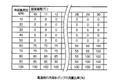
- FIG. 6 shows the optimum flow rate ratio of the cooling water pumps 4 and 5 in which the COP is maximized by performing the above simulation for an arbitrary refrigeration load ratio Q (%) and the outdoor wet bulb temperature TWB in advance.
- Q arbitrary refrigeration load ratio
- TWB outdoor wet bulb temperature
- the flow rate ratio of the high-temperature side cooling water pump 4 at which COP is maximized is 75%.
- the flow rate ratio of the high-temperature side cooling water pump 4 at which COP is maximized is 0% (zero). This indicates that the refrigeration load is small, the high-temperature side refrigerator 1 is stopped, and the cooling water pump 4 that supplies cooling water to the refrigerator 1 is stopped.
- FIG. 7 shows the optimum airflow ratio of the cooling tower fans 21a and 21b in which the COP is maximized by performing the above simulation for an arbitrary refrigeration load ratio Q (%) and the outside air wet bulb temperature TWB in advance.
- Q arbitrary refrigeration load ratio
- TWB outside air wet bulb temperature
- the air volume ratio of the high-temperature side cooling tower fan 21a at which COP is maximized is 75%.
- the air volume ratio of the high-temperature side cooling tower fan 21a at which COP is maximized is 0% (zero). This indicates that the refrigeration load is small, the high-temperature side refrigerator 1 is stopped, and the cooling tower fan 21a for producing the cooling water supplied to the refrigerator 1 is stopped.
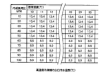
- FIG. 8 shows the optimum load distribution ratio at which the COP is maximized by performing the above simulation for an arbitrary refrigeration load ratio Q (%) and the outdoor wet bulb temperature TWB in advance, and the high temperature side refrigerator 1 is obtained from the optimum load distribution ratio.
- Table of optimum outlet cold water temperature According to the table of FIG. 8, for example, when the refrigeration load ratio Q (%) is 10% and the wet bulb temperature is 10 ° C., the optimum outlet cold water temperature at which COP is maximized is 13.4 ° C. Here, 13.4 ° C. is the temperature of the cold water recirculated from the external load device B. When the refrigeration load ratio Q (%) is 60% and the wet bulb temperature is 10 ° C., the optimum outlet cold water temperature at which COP is maximized is 8.9 ° C.
- the wet bulb temperature is shown from 10 ° C. to 30 ° C. in increments of 1 ° C., but is not limited to this temperature range.
- the region where the refrigeration load ratio Q (%) is 10 to 50% indicates that the operation control condition is such that the COP becomes maximum when the high temperature side refrigerator 1 is stopped. ing. That is, the control command unit 25 stops the cooling water pump 4 and the cooling tower fan 21a corresponding to the high temperature side refrigerator 1, and opens the on-off valve 15 of the bypass pipe 17b to be recirculated from the external load device B. The cold water is controlled to flow directly to the low temperature side refrigerator 2.
- the on-off valve 15 of the bypass pipe 17b is opened so that the cold water flows by bypassing the high-temperature side refrigerator 1 so that the cold water is stopped.
- Distribution resistance can be made smaller than flowing through the side refrigerator.
- control means 23 calculates the refrigeration load ratio Q (%), the outdoor wet bulb temperature TWB, and the cold water flow rate ratio L rate (%) from the measured values of each measuring device and inputs them to the simulator 24. However, these calculations may also be performed by the simulator 24.
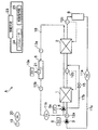
- FIG. 9 is another embodiment of FIG. 1.
- One cooling tower 6 is provided for a plurality of refrigerators, and the cooling water cooled by the cooling tower fan 21 of the cooling tower 6 is supplied to the plurality of refrigerators 1 and 2. This is the case of distributing by each cooling water pump. That is, the cooling water cooled by the cooling tower fan 21 of the cooling tower 6 flows through the cooling water outlet pipe 18.
- the cooling water that has flowed through the cooling water outlet pipe 18 is divided into a high temperature side pipe 18A that supplies cooling water to the high temperature side refrigerator 1 and a low temperature side pipe 18B that supplies cooling water to the low temperature side refrigerator 2. .
- cooling water heat-exchanged with the refrigerator 1 flows through a high temperature side piping
- the cooling water heat-exchanged with the refrigerator 2 flows through a low temperature side piping, merges with a cooling water inlet piping, and returns to a cooling tower.
- a cooling water pump is provided in each of the high temperature side pipe and the low temperature side pipe, and the flow rate ratio of the cooling water supplied to the refrigerator 1 and the refrigerator 2 is changed by controlling the rotation speed of each cooling water pump.
- the temperature indicating controller shown in FIG. 1 is not provided, but it may be provided.
- Other apparatus configurations are basically the same as those in FIG.
- FIG. 10 shows still another embodiment of FIG. 1.
- One cooling tower 6 is provided for a plurality of refrigerators 1, 2, and cooling water cooled by the cooling tower fan 21 of the cooling tower 6 is cooled by one unit.
- the water pump 4 sequentially supplies the low temperature side refrigerator 2 from the high temperature side refrigerator 1 of the plurality of refrigerators 1 and 2.
- a Cold heat source device B External load device 1, 2 Refrigerator 3 Cold water pump 4, 5 Cooling water pump 6, 7 Cooling tower 8, 9a, 9b, 10a, 10b Inverter 11a Cold water flow meter 11b, 11c Cooling water flow meter 12a 1 thermometer 12b 2nd thermometer 12c 3rd thermometer 13a, 14a Inlet thermometer 13b, 14b Outlet thermometer 15 On-off valve 16a, 16b, 16c, 16d Temperature indicating controller 17a Cold water piping 17b Bypass piping 18, 18a, 18b , 18A, 18B Cooling water piping 19 Outside air temperature meter 20 Outside air humidity meter 21a, 21b Cooling tower fan 23 Control means 24 Simulator 25 Control command section
Landscapes
- Engineering & Computer Science (AREA)
- Life Sciences & Earth Sciences (AREA)
- Sustainable Development (AREA)
- Chemical & Material Sciences (AREA)
- Combustion & Propulsion (AREA)
- Mechanical Engineering (AREA)
- General Engineering & Computer Science (AREA)
- Air Conditioning Control Device (AREA)
- Other Air-Conditioning Systems (AREA)
Abstract
La présente invention a trait à un système de commande du fonctionnement destiné à un dispositif de source de froid, lequel système est équipé : d'un moyen d'acquisition (23) permettant d'acquérir la température humide de l'air extérieur, le rapport de charge calorifique et le rapport de débit d'eau froide ; d'un simulateur (24) permettant de simuler le rapport de débit optimal, le rapport de volume d'air optimal et le rapport de distribution de charge optimal afin de maximiser le COP de l'ensemble du dispositif de source de froid (A) en utilisant le rapport de débit entre les pompes à eau de refroidissement (3, 4) des réfrigérateurs respectifs (1, 2), le rapport de volume d'air entre les ventilateurs de tour de refroidissement (6, 7) et le rapport de distribution de charge auquel le rapport de charge calorifique est distribué entre les réfrigérateurs (1, 2) en tant que variables dans les conditions de la température humide de l'air extérieur acquise, le rapport de charge calorifique et le rapport de débit d'eau froide ; et d'un moyen de commande (25) permettant de contrôler les pompes à eau froide (4, 5) des réfrigérateurs (1, 2) en fonction du rapport de débit d'eau froide, de contrôler les températures d'eau froide de sortie des réfrigérateurs (1, 2) en fonction du rapport de distribution de charge optimal obtenu par le simulateur (24) et de contrôler les pompes à eau de refroidissement (3, 4) et les ventilateurs de tour de refroidissement (21a, 21b) des tours de refroidissement respectives (6, 7) en fonction du rapport de débit optimal et du rapport de volume d'air optimal.
Priority Applications (1)
| Application Number | Priority Date | Filing Date | Title |
|---|---|---|---|
| SG2013078696A SG194589A1 (en) | 2011-04-22 | 2012-04-20 | Operation control system for cold generation apparatus |
Applications Claiming Priority (2)
| Application Number | Priority Date | Filing Date | Title |
|---|---|---|---|
| JP2011-096375 | 2011-04-22 | ||
| JP2011096375A JP5777929B2 (ja) | 2011-04-22 | 2011-04-22 | 冷熱源装置の運転制御システム |
Publications (1)
| Publication Number | Publication Date |
|---|---|
| WO2012144581A1 true WO2012144581A1 (fr) | 2012-10-26 |
Family
ID=47041685
Family Applications (1)
| Application Number | Title | Priority Date | Filing Date |
|---|---|---|---|
| PCT/JP2012/060665 Ceased WO2012144581A1 (fr) | 2011-04-22 | 2012-04-20 | Système de commande du fonctionnement destiné à un dispositif de source de froid |
Country Status (3)
| Country | Link |
|---|---|
| JP (1) | JP5777929B2 (fr) |
| SG (1) | SG194589A1 (fr) |
| WO (1) | WO2012144581A1 (fr) |
Cited By (6)
| Publication number | Priority date | Publication date | Assignee | Title |
|---|---|---|---|---|
| CN108061401A (zh) * | 2018-01-17 | 2018-05-22 | 重庆聚科空调设备有限公司 | 一种集成式双高效冷热水机组 |
| CN110036248A (zh) * | 2016-12-07 | 2019-07-19 | 三菱重工制冷空调系统株式会社 | 热源系统、控制装置、控制方法以及程序 |
| CN114719355A (zh) * | 2022-04-06 | 2022-07-08 | 中煤科工(天津)清洁能源研究院有限公司 | 温度调节系统及计算方法 |
| CN116007078A (zh) * | 2021-10-21 | 2023-04-25 | 中国移动通信集团设计院有限公司 | 一种制冷系统的运行参数获取方法、装置及设备 |
| CN116379588A (zh) * | 2023-04-08 | 2023-07-04 | 广州施杰节能科技有限公司 | 一种冷水主机负荷分配寻优调节方法及其系统 |
| EP4375589A1 (fr) * | 2022-11-22 | 2024-05-29 | Kovalik Electrotechnics s.r.o. | Connexion de pompes à chaleur et procédé de commande de pompes à chaleur de cette connexion |
Families Citing this family (12)
| Publication number | Priority date | Publication date | Assignee | Title |
|---|---|---|---|---|
| JP6592858B2 (ja) * | 2015-04-14 | 2019-10-23 | 三菱重工サーマルシステムズ株式会社 | 制御装置、制御方法及びプログラム |
| JP6505589B2 (ja) * | 2015-11-30 | 2019-04-24 | 三機工業株式会社 | 熱源制御システムおよび制御方法 |
| JP6750980B2 (ja) * | 2016-08-25 | 2020-09-02 | 高砂熱学工業株式会社 | 空調システムの制御装置、制御方法、制御プログラムおよび空調システム |
| JP6849345B2 (ja) * | 2016-08-25 | 2021-03-24 | 高砂熱学工業株式会社 | 空調システムの制御装置、制御方法および制御プログラム |
| CN106500204A (zh) * | 2016-12-28 | 2017-03-15 | 重庆通用贝园制冷空调设备有限责任公司 | 一种空调系统 |
| CN112857078B (zh) * | 2021-01-07 | 2022-09-06 | 西安木牛能源技术服务有限公司 | 一种动态的冷却塔群水系统水力平衡调节方法及系统 |
| JP7631020B2 (ja) | 2021-02-19 | 2025-02-18 | 三菱重工サーマルシステムズ株式会社 | 制御装置及び熱源システム、並びに制御方法、並びに制御プログラム |
| JP7136965B1 (ja) | 2021-05-06 | 2022-09-13 | 三菱重工サーマルシステムズ株式会社 | 計算装置、計算方法、プログラム、制御装置、制御方法、制御プログラム |
| JP2023139700A (ja) * | 2022-03-22 | 2023-10-04 | 三菱電機株式会社 | 冷凍システムおよび冷凍機制御装置 |
| KR102557884B1 (ko) * | 2022-08-10 | 2023-07-19 | 최성식 | 건물 공조 및 냉동을 위한 수냉식 냉동기 열교환기 제어 시스템 |
| CN116792833B (zh) * | 2023-06-21 | 2026-03-17 | 青岛海尔空调电子有限公司 | 复合能源耦合系统及其控制方法 |
| CN119326584B (zh) * | 2024-12-23 | 2025-03-14 | 成都科瑞普医疗器械有限公司 | 一种气压冷敷设备 |
Citations (5)
| Publication number | Priority date | Publication date | Assignee | Title |
|---|---|---|---|---|
| JPS61225528A (ja) * | 1985-03-30 | 1986-10-07 | Yamatake Honeywell Co Ltd | 直列運転冷凍機の能力制御装置 |
| JP2008134013A (ja) * | 2006-11-29 | 2008-06-12 | Toyo Netsu Kogyo Kk | 冷熱源機の運転制御方法及びこれを用いた冷熱源システム |
| JP2010236728A (ja) * | 2009-03-30 | 2010-10-21 | Mitsubishi Heavy Ind Ltd | 熱源システムおよびその制御方法 |
| JP2010270970A (ja) * | 2009-05-21 | 2010-12-02 | Mitsubishi Heavy Ind Ltd | 熱源システム及びその制御方法並びにプログラム |
| JP2011002111A (ja) * | 2009-06-16 | 2011-01-06 | Shimizu Corp | 熱源機システム運転ナビゲーションシステム |
-
2011
- 2011-04-22 JP JP2011096375A patent/JP5777929B2/ja not_active Expired - Fee Related
-
2012
- 2012-04-20 WO PCT/JP2012/060665 patent/WO2012144581A1/fr not_active Ceased
- 2012-04-20 SG SG2013078696A patent/SG194589A1/en unknown
Patent Citations (5)
| Publication number | Priority date | Publication date | Assignee | Title |
|---|---|---|---|---|
| JPS61225528A (ja) * | 1985-03-30 | 1986-10-07 | Yamatake Honeywell Co Ltd | 直列運転冷凍機の能力制御装置 |
| JP2008134013A (ja) * | 2006-11-29 | 2008-06-12 | Toyo Netsu Kogyo Kk | 冷熱源機の運転制御方法及びこれを用いた冷熱源システム |
| JP2010236728A (ja) * | 2009-03-30 | 2010-10-21 | Mitsubishi Heavy Ind Ltd | 熱源システムおよびその制御方法 |
| JP2010270970A (ja) * | 2009-05-21 | 2010-12-02 | Mitsubishi Heavy Ind Ltd | 熱源システム及びその制御方法並びにプログラム |
| JP2011002111A (ja) * | 2009-06-16 | 2011-01-06 | Shimizu Corp | 熱源機システム運転ナビゲーションシステム |
Cited By (8)
| Publication number | Priority date | Publication date | Assignee | Title |
|---|---|---|---|---|
| CN110036248A (zh) * | 2016-12-07 | 2019-07-19 | 三菱重工制冷空调系统株式会社 | 热源系统、控制装置、控制方法以及程序 |
| CN108061401A (zh) * | 2018-01-17 | 2018-05-22 | 重庆聚科空调设备有限公司 | 一种集成式双高效冷热水机组 |
| CN116007078A (zh) * | 2021-10-21 | 2023-04-25 | 中国移动通信集团设计院有限公司 | 一种制冷系统的运行参数获取方法、装置及设备 |
| CN114719355A (zh) * | 2022-04-06 | 2022-07-08 | 中煤科工(天津)清洁能源研究院有限公司 | 温度调节系统及计算方法 |
| CN114719355B (zh) * | 2022-04-06 | 2023-02-03 | 中煤科工(天津)清洁能源研究院有限公司 | 温度调节系统及计算方法 |
| EP4375589A1 (fr) * | 2022-11-22 | 2024-05-29 | Kovalik Electrotechnics s.r.o. | Connexion de pompes à chaleur et procédé de commande de pompes à chaleur de cette connexion |
| CN116379588A (zh) * | 2023-04-08 | 2023-07-04 | 广州施杰节能科技有限公司 | 一种冷水主机负荷分配寻优调节方法及其系统 |
| CN116379588B (zh) * | 2023-04-08 | 2023-09-12 | 广州施杰节能科技有限公司 | 一种冷水主机负荷分配寻优调节方法及其系统 |
Also Published As
| Publication number | Publication date |
|---|---|
| SG194589A1 (en) | 2013-12-30 |
| JP5777929B2 (ja) | 2015-09-09 |
| JP2012225629A (ja) | 2012-11-15 |
Similar Documents
| Publication | Publication Date | Title |
|---|---|---|
| JP5777929B2 (ja) | 冷熱源装置の運転制御システム | |
| JP6334230B2 (ja) | 冷凍機システム | |
| JP5615559B2 (ja) | 冷却システム | |
| JP4936961B2 (ja) | 空調システム制御装置 | |
| US11808483B2 (en) | Systems and methods for controlling free cooling and integrated free cooling | |
| JP4829147B2 (ja) | 空気調和設備 | |
| JP5514787B2 (ja) | 環境試験装置 | |
| JP5299680B2 (ja) | 冷却システムおよび冷却方法 | |
| US9175889B2 (en) | Heat source system and control method thereof | |
| TW201809560A (zh) | 用以控制冷凍系統之系統及方法 | |
| KR20130069805A (ko) | 열원 시스템 및 열원 시스템의 대수 제어 방법 | |
| JP5890697B2 (ja) | 冷却塔ファン制御装置および方法 | |
| JP2011012904A (ja) | フリークーリング用の冷熱源装置並びに冷却システム及び冷却方法 | |
| JP2013224794A (ja) | クリーンルームの空調制御方法とその装置 | |
| JP6449009B2 (ja) | 空調システム | |
| JP2011226680A (ja) | 冷却水製造設備 | |
| CN118163571A (zh) | 用于新能源汽车热管理系统的控制系统、方法及相关装置 | |
| JP5200497B2 (ja) | 冷水供給方法、冷水供給装置、及び冷水供給装置の制御方法 | |
| JP2007127321A (ja) | 冷凍機の冷水負荷率制御装置 | |
| JP2018031537A (ja) | 空調システムの制御装置、制御方法および制御プログラム | |
| JP2023151359A (ja) | 空調システムの運転方法および空調システム | |
| CN119737684A (zh) | 一种空调冷冻水系统冷量-流量一体控制方法、装置、设备及介质 | |
| CN118158976A (zh) | 变频空调和对变频空调进行控制的方法 | |
| JP2016048145A (ja) | 熱源システムに使用される制御装置、および該制御装置を備えた熱源システム | |
| JP6586182B2 (ja) | 熱源システムに使用される制御装置、および該制御装置を備えた熱源システム |
Legal Events
| Date | Code | Title | Description |
|---|---|---|---|
| 121 | Ep: the epo has been informed by wipo that ep was designated in this application |
Ref document number: 12774008 Country of ref document: EP Kind code of ref document: A1 |
|
| NENP | Non-entry into the national phase |
Ref country code: DE |
|
| 122 | Ep: pct application non-entry in european phase |
Ref document number: 12774008 Country of ref document: EP Kind code of ref document: A1 |