WO2012144832A2 - Apparatus and method for transmitting acknowledgement information in a tdd communication system - Google Patents

Apparatus and method for transmitting acknowledgement information in a tdd communication system Download PDF

Info

Publication number
WO2012144832A2
WO2012144832A2 PCT/KR2012/003020 KR2012003020W WO2012144832A2 WO 2012144832 A2 WO2012144832 A2 WO 2012144832A2 KR 2012003020 W KR2012003020 W KR 2012003020W WO 2012144832 A2 WO2012144832 A2 WO 2012144832A2
Authority
WO
WIPO (PCT)
Prior art keywords
ack
harq
data
acknowledgement information
tbs
Prior art date
Legal status (The legal status is an assumption and is not a legal conclusion. Google has not performed a legal analysis and makes no representation as to the accuracy of the status listed.)
Ceased
Application number
PCT/KR2012/003020
Other languages
French (fr)
Other versions
WO2012144832A3 (en
Inventor
Aris Papasakellariou
Joon-Young Cho
Current Assignee (The listed assignees may be inaccurate. Google has not performed a legal analysis and makes no representation or warranty as to the accuracy of the list.)
Samsung Electronics Co Ltd
Original Assignee
Samsung Electronics Co Ltd
Priority date (The priority date is an assumption and is not a legal conclusion. Google has not performed a legal analysis and makes no representation as to the accuracy of the date listed.)
Filing date
Publication date
Application filed by Samsung Electronics Co Ltd filed Critical Samsung Electronics Co Ltd
Priority to CN201280019201.5A priority Critical patent/CN103493418B/en
Priority to CA2833750A priority patent/CA2833750C/en
Priority to JP2014506329A priority patent/JP6022543B2/en
Priority to AU2012246830A priority patent/AU2012246830B2/en
Publication of WO2012144832A2 publication Critical patent/WO2012144832A2/en
Publication of WO2012144832A3 publication Critical patent/WO2012144832A3/en
Anticipated expiration legal-status Critical
Priority to AU2016235026A priority patent/AU2016235026B2/en
Ceased legal-status Critical Current

Links

Classifications

    • HELECTRICITY
    • H04ELECTRIC COMMUNICATION TECHNIQUE
    • H04LTRANSMISSION OF DIGITAL INFORMATION, e.g. TELEGRAPHIC COMMUNICATION
    • H04L1/00Arrangements for detecting or preventing errors in the information received
    • H04L1/12Arrangements for detecting or preventing errors in the information received by using return channel
    • H04L1/16Arrangements for detecting or preventing errors in the information received by using return channel in which the return channel carries supervisory signals, e.g. repetition request signals
    • H04L1/1607Details of the supervisory signal
    • H04L1/1614Details of the supervisory signal using bitmaps
    • HELECTRICITY
    • H04ELECTRIC COMMUNICATION TECHNIQUE
    • H04LTRANSMISSION OF DIGITAL INFORMATION, e.g. TELEGRAPHIC COMMUNICATION
    • H04L1/00Arrangements for detecting or preventing errors in the information received
    • H04L1/12Arrangements for detecting or preventing errors in the information received by using return channel
    • H04L1/16Arrangements for detecting or preventing errors in the information received by using return channel in which the return channel carries supervisory signals, e.g. repetition request signals
    • H04L1/1607Details of the supervisory signal
    • H04L1/1621Group acknowledgement, i.e. the acknowledgement message defining a range of identifiers, e.g. of sequence numbers
    • HELECTRICITY
    • H04ELECTRIC COMMUNICATION TECHNIQUE
    • H04LTRANSMISSION OF DIGITAL INFORMATION, e.g. TELEGRAPHIC COMMUNICATION
    • H04L1/00Arrangements for detecting or preventing errors in the information received
    • H04L1/12Arrangements for detecting or preventing errors in the information received by using return channel
    • H04L1/16Arrangements for detecting or preventing errors in the information received by using return channel in which the return channel carries supervisory signals, e.g. repetition request signals
    • H04L1/18Automatic repetition systems, e.g. Van Duuren systems
    • H04L1/1829Arrangements specially adapted for the receiver end
    • H04L1/1861Physical mapping arrangements
    • HELECTRICITY
    • H04ELECTRIC COMMUNICATION TECHNIQUE
    • H04LTRANSMISSION OF DIGITAL INFORMATION, e.g. TELEGRAPHIC COMMUNICATION
    • H04L5/00Arrangements affording multiple use of the transmission path
    • H04L5/14Two-way operation using the same type of signal, i.e. duplex

Definitions

  • the present invention generally relates to wireless communication systems, and more particularly, to the transmission of acknowledgement information in an uplink of a communication system.
  • a communication system includes a DownLink (DL) that conveys transmission signals from a Base Station (BS or NodeB) to User Equipments (UEs) and an UpLink (UL) that conveys transmission signals from UEs to the NodeB.
  • DL DownLink
  • UEs User Equipments
  • UL UpLink
  • a UL conveys transmissions of data signals carrying information content, transmissions of control signals providing control information associated with transmissions of data signals in a DL, and transmissions of Reference Signals (RSs), which are commonly referred to as pilot signals.
  • a DL also conveys transmissions of data signals, control signals, and RSs.
  • UL signals may be transmitted over clusters of contiguous REs using a Discrete Fourier Transform Spread Orthogonal Frequency Division Multiplexing (DFT-S-OFDM) method.
  • DL signals may be transmitted using an OFDM method.
  • UL data signals are conveyed through a Physical Uplink Shared CHannel (PUSCH) and DL data signals are conveyed through a Physical Downlink Shared CHannel (PDSCH).
  • PUSCH Physical Uplink Shared CHannel
  • PDSCH Physical Downlink Shared CHannel
  • a UE In the absence of a PUSCH transmission, a UE conveys UL Control Information (UCI) through a Physical Uplink Control CHannel (PUCCH). However, when a UE has a PUSCH transmission, it may convey UCI with data through the PUSCH.
  • UCI UL Control Information
  • PUCCH Physical Uplink Control CHannel
  • DL control signals may be broadcast or sent in a UE-specific nature. Accordingly, UE-specific control channels can be used, among other purposes, to provide UEs with Scheduling Assignments (SAs) for PDSCH reception (DL SAs) or PUSCH transmission (UL SAs).
  • SAs Scheduling Assignments
  • DL SAs PDSCH reception
  • UL SAs PUSCH transmission
  • the SAs are transmitted from the NodeB to respective UEs using DL Control Information (DCI) formats through respective Physical DL Control CHannels (PDCCHs).
  • DCI DL Control Information
  • the NodeB may configure a UE through higher layer signaling, such as Radio Resource Control (RRC) signaling, a PDSCH, and a PUSCH Transmission Mode (TM).
  • RRC Radio Resource Control
  • TM PUSCH Transmission Mode
  • the PDSCH TM or PUSCH TM is respectively associated with a DL SA or a UL SA, and defines whether the respective PDSCH or PUSCH conveys one data Transport Block (TB) or two data TBs.
  • RRC Radio Resource Control
  • TM PUSCH Transmission Mode
  • PDSCH or PUSCH transmissions are either scheduled to a UE by a NodeB through higher layer signaling or through physical layer signaling (e.g., a PDCCH) using a respective DL SA or UL SA, or correspond to non-adaptive retransmissions for a given Hybrid Automatic Repeat reQuest (HARQ) process.
  • Scheduling by higher layer signaling is referred to as Semi-Persistent Scheduling (SPS), and scheduling by a PDCCH is referred to as dynamic.
  • SPS Semi-Persistent Scheduling
  • a PDCCH may also be used to release an SPS PDSCH. If a UE fails to detect a PDCCH, this event is referred to as Discontinuous Transmission (DTX).
  • DTX Discontinuous Transmission
  • the UCI includes ACKnowledgment (ACK) information associated with a HARQ process (HARQ-ACK).
  • HARQ-ACK ACKnowledgment
  • the HARQ-ACK information may include multiple bits indicating the correct or incorrect detection of multiple data TBs.
  • a correct detection of a data TB is indicated by a positive acknowledgment (i.e., an ACK) while an incorrect detection is indicated by a Negative ACK (NACK).
  • NACK Negative ACK
  • a UE misses (e.g., fails to detect) a PDCCH it may explicitly or implicitly (absence of a signal transmission) indicate DTX (tri-state HARQ-ACK information) or both a DTX and an incorrect reception of a TB can be represented by a NACK (in a combined NACK/DTX state).
  • TTIs Transmission Time Intervals
  • a PDSCH conveys one data TB
  • respective HARQ-ACK information typically consists of one bit that is encoded as a binary ⁇ ', if the TB is correctly received (i.e., an ACK value), and as a binary ⁇ ', if the TB is incorrectly received (i.e., a NACK value).
  • respective HARQ-ACK information typically consists of two bits [OQ CK o CK ] with o K for a first TB and o K for a second TB.
  • FIG. 1 illustrates a conventional TTI for a PUSCH or a PUCCH.
  • a TTI consists of one subframe including two slots for PUSCH 11 OA or PUCCH HOB transmission.
  • Each slot 120A and 120B includes N ⁇ ; b symbols 13 OA used for signaling data or HARQ-ACK information in a
  • N ⁇ b symbols 130B used for HARQ-ACK information in a PUCCH
  • the transmission BandWidth (BW) consists of frequency resource units that are referred to as Physical Resource Blocks (PRBs). Each PRB consists of N s f sub-carriers, or
  • FIG. 2 illustrates a conventional HARQ-ACK transmission structure in a PUCCH subframe slot.
  • CAZAC Constant Amplitude Zero Auto-Correlation
  • FIG. 3 is a block diagram illustrating of a conventional transmitter for a PUCCH.
  • a CAZAC sequence 310 can be used without modulation for an RS or with modulation for HARQ-ACK information.
  • the transmitter in the FIG.3 includes a selector 320, a sub-carrier mapper 330, an IFFT unit 340, a Cyclic Shifter 350, a Cyclic Prefix (CP) inserter 360, and a filter 370 for time windowing.
  • the selector 320 selects a first PRB and a second PRB for transmission of the CAZAC sequence in a first slot and a second slot, respectively.
  • the IFFT unit 340 performs IFFT, and the Cyclic Shifter.350 applies a Cyclic Shift (CS) to the output of the IFFT unit 340.
  • a CP and filtering are applied by the CP inserter 360 and the filter 370.
  • the signal 380 is transmitted. Additional transmitter circuitry such as a Digital-to- Analog Converter (DAC), analog filters, amplifiers, transmitter antennas, etc., are not shown for brevity.
  • DAC Digital-to- Analog Converter
  • FIG. 4 is a block diagram illustrating a conventional receiver diagram for a PUCCH.
  • the receiver in the FIG.3 includes a filter 420 for time windowing, a CP remover 430, a CS restorer 440, a Fast Fourier Transform (FFT) unit 450, a sub-carrier de-mapper 460, a selector 465, and a multiplier 470.
  • An antenna (not shown) receives an analog signal and after further processing units (such as filters, amplifiers, frequency down-converters, and Analog-to-Digital Converters (ADCs) that are not shown for brevity), a digital received signal 410 passes through the filter 420 and the CP remover 430.
  • a CS is restored by the CS restorer 440
  • the FFT 450 unit applies FFT, for sub-carrier demapping in the sub-carrier demapper 460
  • a selector 465 selects REs in a first PRB and a second PRB in a first slot and in a second slot, respectively
  • a multiplier correlates 470 the REs with a replica of a CAZAC sequence 480.
  • the output 490 may then be passed to a channel estimation unit, such as a time-frequency interpolator, when a subframe symbol conveys a RS, or to a detection unit, when a subframe symbol conveys a HARQ-ACK signal.
  • Different CSs of a same CAZAC sequence provide orthogonal CAZAC sequences and can be allocated to different UEs to achieve orthogonal multiplexing of HARQ-ACK signal transmissions in the same PRB. If T S is a symbol duration, the number of such CSs is approximately , where D is a channel propagation delay spread and
  • orthogonal multiplexing may also be in the time domain using Orthogonal Covering Codes (OCC).
  • OCC Orthogonal Covering Codes
  • a HARQ-ACK signal can be modulated by a length-4 OCC, such as a Walsh-Hadamard (WH) OCC
  • WH Walsh-Hadamard
  • an RS can be modulated by a length-3 OCC, such as a DFT OCC (not shown).
  • the multiplexing capacity per PRB increases by a factor of 3 (determined by the OCC with the smaller length).
  • the sets of WH OCCs ⁇ w a , w w 2 , w ⁇ ], and DFT OCCs ⁇ D 0 , D, , D ), are respectively
  • Table 1 presents a mapping for a PUCCH resource « PUCCH used for a HARQ- ACK signal and an RS transmission to an OCC ft oc and a CS a , assuming 6 CS per symbol and a length-3 OCC (with 3 CS used for each OCC). If all resources within a PUCCH PRB are used, resources in an immediately next PRB can be used.
  • Table 1 PUCCH Resource Mapping to OCC and CS.
  • a PDCCH is transmitted in elementary units that are referred to as Control Channel Elements (CCEs).
  • CCEs may consist of 36 REs.
  • UEs are informed of a total number of CCEs, N CCE , through a transmission of a Physical Control Format
  • PCFICH Indicator CHannel
  • the PCFICH indicates a number of OFDM symbols used for PDCCH transmissions in a respective DL subframe.
  • a one-to-one mapping can exist between PUCCH resources (PRB, CS, OCC) for HARQ-ACK signal transmission and PDCCH CCEs. For example, if a single PUCCH resource is used for HARQ-ACK signal transmission, it may be derived from the CCE with the lowest index in a PDCCH conveying a respective DL SA.
  • M ⁇ 1 DL subframes may be associated with a single UL subframe.
  • the association is in the sense that HARQ-ACK information generated in response to reception of data TBs in M ⁇ 1 DL subframes is transmitted in a single UL subframe.
  • PUCCH resource indexing for HARQ-ACK signal transmission can be as described below.
  • N p max ⁇ o,[j j ⁇ 3 ⁇ 4 x (NTM * ⁇ - 4)]/ 3 ⁇ ,
  • N PUCCH is an offset informed to a UE by higher layer signaling
  • sc is a number of sub-carriers
  • ⁇ 3 ⁇ 4 is a number of PRBs in the DL operating BW.
  • HARQ-ACK information in a PUCCH may be conveyed with several methods including HARQ-ACK time-domain bundling and HARQ-ACK multiplexing using channel selection (referring to a selection of a PUCCH resource from a set of available PUCCH resources).
  • HARQ-ACK spatial- domain bundling applies where a UE generates an ACK, only if it receives all data TBs in a PDSCH correctly, and generates a NACK otherwise.
  • HARQ-ACK time-domain bundling With HARQ-ACK time-domain bundling, a UE generates an ACK, only if it receives all TBs in a bundling window correctly, and generates a NACK otherwise. Therefore, HARQ-ACK time-domain bundling results in unnecessary retransmissions as a NACK is sent even when the UE correctly receives some of the TBs in a bundling window.
  • a UE conveys HARQ-ACK information for each DL subframe in a bundling window by selecting a PUCCH resource from a set of possible resources and by modulating the HARQ- ACK signal using QPSK modulation.
  • a UE modulates a HARQ-ACK signal using the QPSK constellation point and selects one of PUCCH resources « PUCCH (0) , " PUCCH ) * OR « PUCCH ( 2 ) > which are respectively determined by a first CCE of a respective PDCCH conveying a DL SA in a respective first, second, or third DL subframe (if any).
  • Explicit DTX indication is possible by including a Downlink Assignment Index (DAI) Information Element (IE), which indicates an accumulative number of PDSCH transmission(s) to a UE (the DAI IE is a counter within a bundling window), in DCI formats conveying DL SAs.
  • DAI Downlink Assignment Index
  • each HARQ-ACK bit conveys an outcome of each PDSCH reception and is encoded as a binary ' , if the respective TB(s) are correctly received (i.e., an ACK), and is encoded as a binary ⁇ ', if the respective TB(s) are incorrectly received (i.e., a NACK). Therefore, an individual HARQ-ACK bit is conveyed for each PDSCH reception.
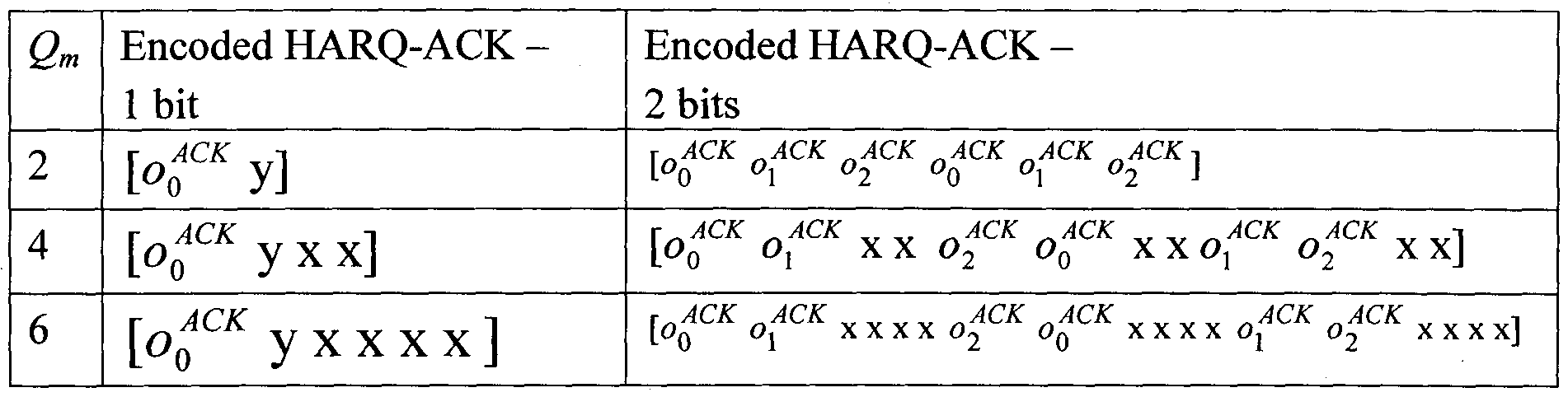
  • O 2 bits [e> 0 o, ] , it is encoded using a (3, 2) simplex code, as described in Table 3 for Q m data modulation bits, where
  • Table 3 Encoding for 1 and 2 HARQ-ACK Information Bits.
  • the coding may be by a (32, 0 ACK ) Reed-Mueller
  • QQ ACK - ⁇ is obtained by a circular repetition of the bit sequence o i > ⁇ » ⁇ 31 , such that the bit sequence length is equal to Q ACK , which is the total number of coded HARQ-ACK symbols in a PUSCH.
  • FIG. 5 is a block diagram illustrating a conventional transmitter for data and HARQ-ACK in a PUSCH.
  • the transmitter includes a data encoder 515, an RM encoder 520, a puncturer/inserter 530, a DFT unit 540, a sub-carrier mapper 550, a selector 555, an IFFT unit 560, a CP inserter 570, and a filter 580 for time windowing.
  • Data information bits 505 and HARQ-ACK information bits 510 are respectively provided to the data encoder 515 and the RM encoder 520.
  • a simplex encoder is used instead of the RM encoder 520. Encoded data bits are subsequently punctured and replaced by encoded HARQ- ACK bits by the puncturer/inserter 530.
  • a selector 555 selects REs corresponding to the PUSCH transmission BW for subcarrier mapping in the sub-carrier mapper 550, which are then input to the IFFT unit 560.
  • a CP is inserted by the CP inserter 570, and the CP inserted signal then passes through the filter 580 before being transmitted 590.
  • additional transmitter circuitry is not illustrated for conciseness. Also, the modulation process for the transmitted bits is omitted for brevity.
  • FIG. 6 is a conventional block diagram illustrating a receiver block for data and HARQ-ACK in a PUSCH.
  • the receiver includes a filter 620 for time windowing, a CP remover630, an FFT unit 640, a sub-carrier de-mapper 650, a selector 655, an Inverse DFT (IDFT) unit 660, a de-multiplexer 670, a data decoder 680, and an RM decoder 685.
  • a filter 620 for time windowing receives a Radio-Frequency (RF) analog signal and further processing units (not shown) convert the analog signal to a digital signal 610
  • RF Radio-Frequency
  • the output of the CP removal unit 630 is provided to the FFT unit 640, and a selector 655 controls the sub-carrier de-mapper 650 to select the REs used by the transmitter.
  • the obtained values are provided to the IDFT unit 660 and the demultiplexer 670, which outputs coded data bits, that the coded data bits are then provided to the data decoder 680 and the coded HARQ-ACK bits are then provided to the RM decoder 685 to respectively output data information bits 690 and HARQ- ACK information bits 695.
  • a simplex decoder is used instead of the RM decoder 685. Similar to the transmitter illustrated in FIG. 5, receiver functionalities such as channel estimation, demodulation, and decoding are not illustrated in FIG. 6 for brevity.
  • a NodeB can configure multiple cells to a UE in both a DL and a UL to effectively provide higher operating BWs.
  • two 20 MHz cells can be configured to a UE.
  • a UE is always configured a DL cell and a UL cell to maintain communication and each such cell is referred to as Primary cell (Pcell). Additional cells a UE may be configured are referred to as Secondary cells (Scells).
  • Pcell Primary cell
  • Scells Secondary cells
  • a transmission of HARQ-ACK information can be in a PUCCH of the UL Pcell.
  • a separate PUCCH resource is assigned in a UL Pcell for HARQ-ACK signal transmission in response to a PDSCH reception in each subframe of a bundling window and each DL cell.
  • a UE performs channel selection according to Table 4 for
  • the value 'any' can be either 'ACK' or 'NACK/DTX'.
  • NACK/DTX any, any ACK, ACK, NACK/DTX W PUCCH, 3 0, 0
  • the present invention has been designed to solve at least the aforementioned limitations and problems in the prior art and to proved at least the advantages described below.
  • An aspect of the present invention is to provide a method for transmitting acknowledgement information efficiently in response to data Transport Blocks (TBs) received in one or more downlink data channels in a Time Division Duplex (TDD) communication system.
  • TBs data Transport Blocks
  • TDD Time Division Duplex
  • Another aspect of the present invention is to provide a method for a UE configured with two or more cells in a TDD system to transmit HARQ-ACK information in a PUSCH, when it transmits HARQ-ACK information using multiplexing with channel selection in a PUCCH.
  • Another aspect of the present invention is to provide a mapping between HARQ-ACK bits transmitted in a PUSCH and the information that these bits represent.
  • Another aspect of the present invention is to provide a same understanding between a NodeB and a UE of the information represented by HARQ-ACK bits a UE transmits in a PUSCH.
  • a method for transmitting acknowledgement information in response to data Transport Blocks (TBs) received in one or more downlink data channels in a Time Division Duplex (TDD) communication system includes generating acknowledgement information respectively representing a reception result for each data TB by a corresponding acknowledgement bit, if a first condition applies, generating acknowledgement information jointly representing state of reception results for a plurality of data TBs, if a second condition applies, and transmitting the generated acknowledgement information in an uplink data channel.
  • TDD Time Division Duplex
  • an apparatus for transmitting acknowledgement information in response to data Transport Blocks (TBs) received in one or more downlink data channels in a Time Division Duplex (TDD) communication system includes a controller for generating acknowledgement information respectively representing a reception result for each data TB by a corresponding acknowledgement bit, if a first condition applies, and generating acknowledgement information jointly representing state of reception results for a plurality of data TBs, if a second condition applies, and a transmitter for transmitting the generated acknowledgement information in an uplink data channel.
  • TDD Time Division Duplex
  • a method for a User Equipment (UE) to transmit acknowledgement information bits in a Physical Uplink Data CHannel (PUSCH) in response to a correct or incorrect detection of data Transport Blocks (TBs) received in one or more Physical Downlink Data CHannels (PDSCHs) or in response to a detection of a control channel releasing a PDSCH transmission over Transmission Time Intervals (TTIs) in a Time Division Duplex (TDD) communication system.
  • PUSCH Physical Uplink Data CHannel
  • PDSCHs Physical Downlink Data CHannels
  • TTIs Transmission Time Intervals
  • the method includes representing, by each acknowledgement information bit, an outcome for the detection of the data TBs or of a control channel releasing a PDSCH transmission in each of the TTIs, if a first condition applies; jointly representing, by all acknowledgement information bits, a set of outcomes for the detection of the data TBs or of the control channel releasing the PDSCH transmission in each of the TTIs, if a second condition applies; and transmitting the acknowledgement information bits in the PUSCH.
  • a method for a User Equipment (UE) configured for receiving Physical Downlink Data CHannels (PDSCHs) over two cells to transmit acknowledgement information in a Physical Uplink Data CHannel (PUSCH) or in a Physical Uplink Control CHannel (PUCCH) in response to a correct or incorrect detection of data Transport Blocks (TBs) received in one or more PDSCHs or in response to a detection of a control channel releasing a PDSCH transmission over Transmission Time Intervals (TTIs) in a Time Division Duplex (TDD) communication system.
  • PUSCH Physical Uplink Data CHannel
  • PUCCH Physical Uplink Control CHannel
  • the method includes jointly representing a first set of outcomes for a detection of the data TBs or of the control channel releasing the PDSCH transmission in the first of the two configured cells and a second set of outcomes for a detection of the data TBs or of the control channel releasing the PDSCH transmission in the second of the two configured cells, wherein each element in the first set and in the second set of outcomes uniquely corresponds to one of the TTIs; selecting one PUCCH resource from four PUCCH resources and one constellation point from four constellation points for transmitting a signal modulated using quaternary phase shift keying to convey the first set and the second set, if the transmission is in the PUCCH; selecting a combination of values of four acknowledgement information bits to represent the first set and the second set, if the transmission is in the PUSCH; and transmitting the acknowledgement information in the PUCCH or in the PUSCH.
  • a method for a User Equipment (UE) configured for receiving Physical Downlink Data CHannels (PDSCHs) over two cells to transmit acknowledgement information in a Physical Uplink Data CHannel (PUSCH) or in a Physical Uplink Control CHannel (PUCCH) in response to a correct or incorrect detection of data Transport Blocks (TBs) received in one or more PDSCHs or in response to a detection of a control channel releasing a PDSCH transmission over Transmission Time Intervals (TTIs) in a Time Division Duplex (TDD) communication system.
  • PUSCH Physical Uplink Data CHannel
  • PUCCH Physical Uplink Control CHannel
  • the method includes jointly representing a first set of outcomes for the detection of the data TBs or of the control channel releasing the PDSCH transmission in a first of the two configured cells and a second set of outcomes for the detection of the data TBs or of the control channel releasing the PDSCH transmission in a second of the two configured cells, wherein each element in the first set and in the second set of outcomes uniquely corresponds to one of the TTIs; determining that the first set of outcomes is included in a first predetermined set of sets and the second set of outcomes is included in a second predetermined set of sets; selecting a combination of values of four acknowledgement information bits to represent the first set and the second set, if a transmission of the acknowledgement information is in the PUSCH; and transmitting the acknowledgement information, if the transmission is in the PUSCH or suspending the transmission of the acknowledgement information, if the transmission is in the PUCCH.
  • a User Equipment (UE) apparatus for transmitting acknowledgement information bits in a Physical Uplink Data CHannel (PUSCH) in response to a correct or incorrect detection of data Transport Blocks (TBs) received in one or more Physical Downlink Data CHannels (PDSCHs) or in response to a detection of a control channel releasing a PDSCH transmission over Transmission Time Intervals (TTIs) in a Time Division Duplex (TDD) communication system.
  • PUSCH Physical Uplink Data CHannel
  • PDSCHs Physical Downlink Data CHannels
  • TTIs Transmission Time Intervals
  • TDD Time Division Duplex
  • the UE apparatus includes a mapper for mapping, to each acknowledgement information bit, an outcome for the detection of the data TBs or of the control channel releasing the PDSCH transmission in each of the TTIs, if a first condition applies; a mapper for jointly mapping, to all acknowledgement information bits, a set of outcomes for the detection of the data TBs or of the control channel releasing the PDSCH transmission in each of the TTIs, if a second condition applies; an encoder for encoding the acknowledgement information bits; a multiplexer for multiplexing the encoded acknowledgement information bits in the PUSCH; and a transmitter for transmitting the PUSCH.
  • a User Equipment (UE) apparatus for transmitting acknowledgement information in a Physical Uplink Data CHannel (PUSCH) or in a Physical Uplink Control CHannel (PUCCH) in response to a correct or incorrect detection of data Transport Blocks (TBs) received in one or more Physical Downlink Data CHannels (PDSCHs) or in response to a detection of a control channel releasing a PDSCH transmission over Transmission Time Intervals (TTIs) in a Time Division Duplex (TDD) communication system.
  • PUSCH Physical Uplink Data CHannel
  • PUCCH Physical Uplink Control CHannel
  • TTIs Transmission Time Intervals
  • the apparatus includes a mapper for jointly mapping a first set of outcomes for the detection of the data TBs or of the control channel releasing the PDSCH transmission in a first of the two configured cells, and a second set of outcomes for the detection of the data TBs or of the control channel releasing the PDSCH transmission in the second of the two configured cells, wherein each element in the first set and in the second set of outcomes uniquely corresponds to one of the TTIs; a selector for selecting one PUCCH resource from four PUCCH resources and one constellation point from four constellation points for transmitting a signal modulated using quaternary phase shift keying to convey the first set and the second.
  • a selector for selecting a combination of values of four acknowledgement information bits to represent the first set and the second set, if the transmission is in the PUSCH; and a transmitter for transmitting the acknowledgement information in the PUCCH or in the PUSCH.
  • a User Equipment (UE) apparatus for transmitting acknowledgement information in a Physical Uplink Data CHannel (PUSCH) or in a Physical Uplink Control CHannel (PUCCH) in response to a correct or incorrect detection of data Transport Blocks (TBs) received in one or more Physical Downlink Data CHannels (PDSCHs) or in response to a detection of a control channel releasing a PDSCH transmission over Transmission Time Intervals (TTIs) in a Time Division Duplex (TDD) communication system.
  • PUSCH Physical Uplink Data CHannel
  • PUCCH Physical Uplink Control CHannel
  • TTIs Transmission Time Intervals
  • the apparatus includes a mapper for jointly mapping a first set of outcomes for the detection of the data TBs or of the control channel releasing the PDSCH transmission in a first of the two configured cells and a second set of outcomes for the detection of the data TBs or of the control channel releasing the PDSCH transmission in a second of the two configured cells, wherein each element in the first set and in the second set of outcomes uniquely corresponds to one of the TTIs; a comparator for determining that the first set of outcomes is included in a first predetermined set of sets and the second set of outcomes is included in a second predetermined set of sets; a selector for selecting a combination of values of four acknowledgement information bits to represent the first set and the second set, if a transmission of the acknowledgement information is in the PUSCH; and a transmitter for transmitting the acknowledgement information, if the transmission is in the PUSCH, or suspending the transmission of the acknowledgement information, if it is in the PUCCH.
  • a mapper for jointly mapping a first set of
  • FIG. 1 is a diagram illustrating a conventional TTI for a PUSCH or for a PUCCH
  • FIG. 2 is a diagram illustrating a conventional HARQ-ACK transmission structure in a PUCCH subframe slot
  • FIG. 3 is a block diagram illustrating a conventional transmitter for a PUCCH
  • FIG. 4 is a block diagram illustrating a conventional receiver for a PUCCH
  • FIG. 5 is a block diagram illustrating a conventional transmitter for data and HARQ-ACK in a PUSCH
  • FIG. 6 is a block diagram illustrating a conventional receiver for data and HARQ-ACK in a PUSCH
  • FIG. 7 is a flowchart illustrating a method of identifying HARQ-ACK bit representation depending on a number of configured cells and on a value of a bundling window, according to an embodiment of the present invention
  • FIG. 8 is a flowchart illustrating an encoding and decoding process of HARQ- ACK information for a UE configured with two cells, depending on a value of a bundling window, according to an embodiment of the present invention
  • FIG. 10 is a block diagram illustrating a transmitter for transmitting data and HARQ-ACK information in a PUSCH, according to an embodiment of the present invention.
  • FIG. 11 is a block diagram illustrating a receiver for receiving data and HARQ-ACK information in a PUSCH, according to an embodiment of the present invention.
  • the value of M i.e., a number of PDSCHs for which a UE provides HARQ-ACK information or a size of bundling window or a number of TTIs
  • M can either be fixed, as defined by a bundling window size for a particular configuration of a TDD system, or be variable, as defined by a value of a DAI IE in a UL SA conveyed by a PDCCH scheduling a PUSCH transmission, if such a UL SA exists.
  • HARQ-ACK information may also be generated in response to a PDCCH that does not schedule a PDSCH reception, but instead indicates a release of a Semi-Persistently Scheduled (SPS) PDSCH.
  • SPS Semi-Persistently Scheduled
  • This mapping is performed under the constraint that the number of HARQ-ACK information bits input to an RM code is limited to four, as HARQ-ACK multiplexing with channel selection in a PUCCH is assumed to be supported for only up to four HARQ-ACK information bits conveying different HARQ-ACK states. That is, two bits are conveyed through the selection of a PUCCH resource among four available resources, and another two bits are conveyed through a QPSK modulated signal by the respective constellation points.
  • the mapping of HARQ-ACK information to four input bits of an RM encoder for the above operating scenario includes HARQ-ACK states (a HARQ-ACK state is a set of correct or incorrect detection outcomes for data TBs) conveying combinations for values of HARQ-ACK bits as shown in Tables 4 and 5. Therefore, all four HARQ- ACK information bits are jointly considered and an individual HARQ-ACK bit does not have a respective individual interpretation (as it does not indicate an individual correct or incorrect detection outcome for data TBs).
  • FIG. 7 is a flowchart illustrating a method of identifying HARQ-ACK bit representation depending on a number of configured cells and on a value of a bundling window, according to an embodiment of the present invention.
  • the meaning of HARQ-ACK information bits in a PUSCH depends on whether a UE is configured one or two cells in step 710. If a UE is configured one cell, in step 720, the PUSCH transmitter or receiver determines that each HARQ-ACK information bit represents an outcome (e.g., ACK for binary T or NACK/DTX for binary ⁇ ') for a reception of TB(s) in a corresponding PDSCH, regardless of the value of M .
  • an outcome e.g., ACK for binary T or NACK/DTX for binary ⁇ '
  • HARQ-ACK spatial-domain bundling applies if a PDSCH conveys multiple TBs, that a DTX state and a NACK state are jointly represented, and the explicit DTX feedback is not supported in a PUSCH; however, the reverse may also apply.
  • M the representation of HARQ-ACK information bits depends on the value of M in step 730. If M is smaller than or equal to 2, in step 740, the PUSCH transmitter or receiver determines that each HARQ-ACK information bit again represents an outcome (ACK for binary T or NACK/DTX for binary ⁇ ') for a reception of TB(s) in a corresponding PDSCH.
  • step 750 the PUSCH transmitter or receiver determines that each HARQ-ACK information bit does not provide any information on its own and all HARQ-ACK information bits are jointly considered to indicate a HARQ-ACK state (set of outcomes for correct or incorrect detection of data TB(s) in respective PDSCH(s)) corresponding to both cells and all PDSCHs for which HARQ-ACK information is provided by a UE.
  • HARQ- ACK states as represented in Tables 4 and H using channel selection, by the four input bits an RM encoder for transmission in a PUSCH.
  • This representation is obtained by one-to-one mapping of a PUCCH resource and a constellation point of a QPSK modulation of a
  • RM input bits for four PUCCH resources and of the other two RM input bits for the QPSK constellation points in a PUCCH may be used.
  • FIG. 8 illustrates encoding and decoding of HARQ-ACK information for a UE configured with two cells depending on a value of a bundling window, according to an embodiment of the present invention.
  • each HARQ-ACK information bit represents an outcome (e.g., ACK or NACK/DTX) of a respective PDSCH reception.
  • a same understanding is established between a UE and a serving NodeB for the inclusion of HARQ-ACK information in a PUSCH. Consequently, a serving NodeB is not required to detect whether a particular set of PUSCH REs conveys data information or HARQ-ACK information, because such detection may not be reliable.
  • HARQ-ACK signal transmission in a PUCCH such detection is relatively simple as a NodeB can decide whether a signal is transmitted or not by merely computing the received energy in candidate PUCCH resources.
  • the respective DCI format is assumed to include a DAI IE informing a UE whether or not a NodeB expects it to transmit HARQ-ACK information in a PUSCH.
  • This DAI IE may also provide additional information, e.g., the maximum number of PDSCH transmitted to a UE either in the Pcell or in the Scell, and the value of M can be set equal to this number. If a PUSCH transmission is SPS and not scheduled by a UL SA, then a UE may include HARQ-ACK information in a PUSCH for all DL subframes in a bundling window.
  • M is then equal to the bundling window size.
  • the last state in Table 4 is overlapped with the second to last state in Table 6 and both are represented by ⁇ 0, 0, 0, 0 ⁇ input bits to an RM encoder.
  • the last two states in Table 5 are overlapped with the ⁇ NACK, any, any, any ⁇ and the ⁇ NACK/DTX, any, any, any ⁇ states in Table 7 for the Pcell and the Scell, respectively, and are represented by ⁇ 0, 0, 0, 0 ⁇ input bits to an RM encoder.
  • HARQ-ACK information When HARQ-ACK information is to be transmitted in a PUCCH, there is no HARQ-ACK signal transmission for these HARQ-ACK states in step 940.
  • HARQ-ACK information When HARQ-ACK information is to be transmitted in a PUSCH, ⁇ 0, 0, 0, 0 ⁇ bits are used to represent these HARQ-ACK states in step 950.
  • FIG. 10 illustrates block diagram of a transmitter for data and HARQ-ACK in a PUSCH, according to an embodiment of the present invention.
  • a representation of HARQ-ACK information bits depends on the number of cells a UE is configured and on whether each HARQ-ACK information bit informs of an outcome for a respective PDSCH reception in a respective cell or whether all HARQ-ACK information bits jointly inform of HARQ-ACK states corresponding to M PDSCH receptions in both cells.
  • each HARQ-ACK information bit corresponds to an outcome (ACK or NACK/DTX) of a respective PDSCH reception as described with reference to FIG. 5.
  • a UE transmitter as illustrated in FIG. 10 operates similarly to the transmitter of FIG.
  • FIG. 1 1 illustrates a block diagram of a receiver for data and HARQ-ACK in a PUSCH, according to an embodiment of the present invention.
  • a representation of HARQ-ACK information bits depends on the number of cells a UE is configured and on whether each HARQ-ACK information bit informs of an outcome for a respective PDSCH reception in a respective cell or whether all HARQ-ACK information bits jointly inform of HARQ-ACK states corresponding to M PDSCH receptions in both cells.
  • each HARQ-ACK information bit corresponds to an outcome (ACK or NACK/DTX) of a respective PDSCH reception, as described with reference to FIG. 6.
  • a NodeB receiver as illustrated in FIG. 11 operates similarly to the receiver illustrated in FIG.
  • One or more blocks in a transmitter and a receiver described in embodiments of the present invention can be implemented into a controller and the controller generates or receives acknowledgement bits (i.e. acknowledgement information) according to the present invention.
  • acknowledgement bits i.e. acknowledgement information

Landscapes

  • Engineering & Computer Science (AREA)
  • Signal Processing (AREA)
  • Computer Networks & Wireless Communication (AREA)
  • Mobile Radio Communication Systems (AREA)
  • Detection And Prevention Of Errors In Transmission (AREA)
  • Digital Transmission Methods That Use Modulated Carrier Waves (AREA)

Abstract

ABSTRACT Methods and apparatus are described for a User Equipment (UE) configured with multiple cells in the downlink of a time division duplex communication system to transmit HARQ-ACK information in a Physical Uplink Shared Channel (PUSCH), to map HARQ-ACK bits transmitted in a PUSCH to information regarding correct or incorrect detections of data transport blocks in different cells and different transmission time intervals, and to provide a same understanding with an intended reception point of the information represented by HARQ-ACK bits the UE transmits in a PUSCH.

Description

APPARATUS AND METHOD FOR TRANSMITTING
ACKNOWLEDGEMENT INFORMATION IN A TDD COMMUNICATION
SYSTEM
BACKGROUND OF THE INVENTION
1. Field of the Invention
The present invention generally relates to wireless communication systems, and more particularly, to the transmission of acknowledgement information in an uplink of a communication system.
2. Description of the Art
A communication system includes a DownLink (DL) that conveys transmission signals from a Base Station (BS or NodeB) to User Equipments (UEs) and an UpLink (UL) that conveys transmission signals from UEs to the NodeB.
More specifically, a UL conveys transmissions of data signals carrying information content, transmissions of control signals providing control information associated with transmissions of data signals in a DL, and transmissions of Reference Signals (RSs), which are commonly referred to as pilot signals. A DL also conveys transmissions of data signals, control signals, and RSs. UL signals may be transmitted over clusters of contiguous REs using a Discrete Fourier Transform Spread Orthogonal Frequency Division Multiplexing (DFT-S-OFDM) method. DL signals may be transmitted using an OFDM method.
UL data signals are conveyed through a Physical Uplink Shared CHannel (PUSCH) and DL data signals are conveyed through a Physical Downlink Shared CHannel (PDSCH).
In the absence of a PUSCH transmission, a UE conveys UL Control Information (UCI) through a Physical Uplink Control CHannel (PUCCH). However, when a UE has a PUSCH transmission, it may convey UCI with data through the PUSCH.
DL control signals may be broadcast or sent in a UE-specific nature. Accordingly, UE-specific control channels can be used, among other purposes, to provide UEs with Scheduling Assignments (SAs) for PDSCH reception (DL SAs) or PUSCH transmission (UL SAs). The SAs are transmitted from the NodeB to respective UEs using DL Control Information (DCI) formats through respective Physical DL Control CHannels (PDCCHs).
The NodeB may configure a UE through higher layer signaling, such as Radio Resource Control (RRC) signaling, a PDSCH, and a PUSCH Transmission Mode (TM). The PDSCH TM or PUSCH TM is respectively associated with a DL SA or a UL SA, and defines whether the respective PDSCH or PUSCH conveys one data Transport Block (TB) or two data TBs.
PDSCH or PUSCH transmissions are either scheduled to a UE by a NodeB through higher layer signaling or through physical layer signaling (e.g., a PDCCH) using a respective DL SA or UL SA, or correspond to non-adaptive retransmissions for a given Hybrid Automatic Repeat reQuest (HARQ) process. Scheduling by higher layer signaling is referred to as Semi-Persistent Scheduling (SPS), and scheduling by a PDCCH is referred to as dynamic. A PDCCH may also be used to release an SPS PDSCH. If a UE fails to detect a PDCCH, this event is referred to as Discontinuous Transmission (DTX).
The UCI includes ACKnowledgment (ACK) information associated with a HARQ process (HARQ-ACK). The HARQ-ACK information may include multiple bits indicating the correct or incorrect detection of multiple data TBs. Typically, a correct detection of a data TB is indicated by a positive acknowledgment (i.e., an ACK) while an incorrect detection is indicated by a Negative ACK (NACK). If a UE misses (e.g., fails to detect) a PDCCH, it may explicitly or implicitly (absence of a signal transmission) indicate DTX (tri-state HARQ-ACK information) or both a DTX and an incorrect reception of a TB can be represented by a NACK (in a combined NACK/DTX state).
In Time Division Duplex (TDD) systems, DL and UL transmissions occur in different Transmission Time Intervals (TTIs), which are referred to as subframes. For example, in a frame including 10 subframes, some the subframes may be used for DL transmissions and some may be used for UL transmissions. If a PDSCH conveys one data TB, respective HARQ-ACK information typically consists of one bit that is encoded as a binary Ί', if the TB is correctly received (i.e., an ACK value), and as a binary Ό', if the TB is incorrectly received (i.e., a NACK value). If a PDSCH conveys two data TBs, in accordance with a Single-User Multiple Input Multiple Output (SU-MIMO) transmission method, respective HARQ-ACK information typically consists of two bits [OQ CK o CK ] with o K for a first TB and o K for a second TB.
FIG. 1 illustrates a conventional TTI for a PUSCH or a PUCCH.
Referring to FIG. 1, a TTI consists of one subframe including two slots for PUSCH 11 OA or PUCCH HOB transmission. Each slot 120A and 120B includes N^;b symbols 13 OA used for signaling data or HARQ-ACK information in a
PUSCH, or N^b symbols 130B used for HARQ-ACK information in a PUCCH, and
Reference Signals (RS) 140A or 140B, which are used for channel estimation and coherent demodulation of received data or HARQ-ACK information. The transmission BandWidth (BW) consists of frequency resource units that are referred to as Physical Resource Blocks (PRBs). Each PRB consists of Nsf sub-carriers, or
Resource Elements (REs). For PUSCH transmission, a UE is allocated MmsCH PRBs for a total of S P C USCH = PUSCH · N™ REs 150A. For PUCCH transmission, a UE is allocated 1 PRB 150B, which may be in two different BW locations in each of the two subframe slots.
FIG. 2 illustrates a conventional HARQ-ACK transmission structure in a PUCCH subframe slot.
Referring to FIG. 2, HARQ-ACK bits b 210 modulate 220 a Constant Amplitude Zero Auto-Correlation (CAZAC) sequence 230, for example, using Binary Phase Shift Keying (BPSK) with b = b0 or Quaternary Phase Shift Keying
(QPSK) with b = (b0, bl). The modulated CAZAC sequence is then transmitted after performing an Inverse Fast Frequency Transform (IFFT) 240. The RS is transmitted through a non-modulated CAZAC sequence after performing an IFFT 250. FIG. 3 is a block diagram illustrating of a conventional transmitter for a PUCCH.
Referring to FIG. 3, a CAZAC sequence 310 can be used without modulation for an RS or with modulation for HARQ-ACK information. The transmitter in the FIG.3 includes a selector 320, a sub-carrier mapper 330, an IFFT unit 340, a Cyclic Shifter 350, a Cyclic Prefix (CP) inserter 360, and a filter 370 for time windowing.. For sub-carrier mapping in the sub-carrier mapper 330, The selector 320 selects a first PRB and a second PRB for transmission of the CAZAC sequence in a first slot and a second slot, respectively. Subsequently, the IFFT unit 340 performs IFFT, and the Cyclic Shifter.350 applies a Cyclic Shift (CS) to the output of the IFFT unit 340. A CP and filtering are applied by the CP inserter 360 and the filter 370. Thereafter, the signal 380 is transmitted. Additional transmitter circuitry such as a Digital-to- Analog Converter (DAC), analog filters, amplifiers, transmitter antennas, etc., are not shown for brevity.
FIG. 4 is a block diagram illustrating a conventional receiver diagram for a PUCCH.
Referring to FIG. 4, The receiver in the FIG.3 includes a filter 420 for time windowing, a CP remover 430, a CS restorer 440, a Fast Fourier Transform (FFT) unit 450, a sub-carrier de-mapper 460, a selector 465, and a multiplier 470. An antenna (not shown) receives an analog signal and after further processing units (such as filters, amplifiers, frequency down-converters, and Analog-to-Digital Converters (ADCs) that are not shown for brevity), a digital received signal 410 passes through the filter 420 and the CP remover 430. Subsequently, a CS is restored by the CS restorer 440, the FFT 450 unit applies FFT, for sub-carrier demapping in the sub-carrier demapper 460, a selector 465 selects REs in a first PRB and a second PRB in a first slot and in a second slot, respectively, and a multiplier correlates 470 the REs with a replica of a CAZAC sequence 480. The output 490 may then be passed to a channel estimation unit, such as a time-frequency interpolator, when a subframe symbol conveys a RS, or to a detection unit, when a subframe symbol conveys a HARQ-ACK signal. Different CSs of a same CAZAC sequence provide orthogonal CAZAC sequences and can be allocated to different UEs to achieve orthogonal multiplexing of HARQ-ACK signal transmissions in the same PRB. If TS is a symbol duration, the number of such CSs is approximately
Figure imgf000006_0001
, where D is a channel propagation delay spread and |_ J is a floor function that rounds a number to its immediately lower integer.
In addition to orthogonal multiplexing of HARQ-ACK signals and an RS in a same PRB using different CS of a CAZAC sequence, orthogonal multiplexing may also be in the time domain using Orthogonal Covering Codes (OCC). For example, in FIG. 2, a HARQ-ACK signal can be modulated by a length-4 OCC, such as a Walsh-Hadamard (WH) OCC, while an RS can be modulated by a length-3 OCC, such as a DFT OCC (not shown). When using an OCC, the multiplexing capacity per PRB increases by a factor of 3 (determined by the OCC with the smaller length). The sets of WH OCCs {wa, w w2, w^], and DFT OCCs {D0, D, , D ), are respectively
Figure imgf000006_0002
Figure imgf000006_0003
Table 1 presents a mapping for a PUCCH resource «PUCCH used for a HARQ- ACK signal and an RS transmission to an OCC ftoc and a CS a , assuming 6 CS per symbol and a length-3 OCC (with 3 CS used for each OCC). If all resources within a PUCCH PRB are used, resources in an immediately next PRB can be used.
Table 1 : PUCCH Resource Mapping to OCC and CS. OCC noc for a HARQ-ACK and for an RS
CS W0, D0 WX, D,
0 ^PUCCH ~ ^ ^PUCCH _ ^
1 WPUCCH ^
2 WPUCCH ~ 1 nPUCCH ~ ^
3 "PUCCH _ 4
4 "PUCCH ~~ 2 WPUCCH ~~ ^
5 WPUCCH ~ ^
A PDCCH is transmitted in elementary units that are referred to as Control Channel Elements (CCEs). Each CCE may consist of 36 REs. UEs are informed of a total number of CCEs, NCCE , through a transmission of a Physical Control Format
Indicator CHannel (PCFICH) by a serving NodeB. The PCFICH indicates a number of OFDM symbols used for PDCCH transmissions in a respective DL subframe. A one-to-one mapping can exist between PUCCH resources (PRB, CS, OCC) for HARQ-ACK signal transmission and PDCCH CCEs. For example, if a single PUCCH resource is used for HARQ-ACK signal transmission, it may be derived from the CCE with the lowest index in a PDCCH conveying a respective DL SA.
In TDD systems, DL and UL transmissions occur in different subframes and M≥ 1 DL subframes may be associated with a single UL subframe. The association is in the sense that HARQ-ACK information generated in response to reception of data TBs in M≥ 1 DL subframes is transmitted in a single UL subframe. This set of M≥ 1 DL subframes is commonly referred to as a bundling window. Denoting a DL subframe index by m = 0,1,···, - 1 , a number of CCEs for a PCFICH value of p ( N0 = 0) by N , and a first PDCCH CCE of a DL SA in subframe m by nCCE{m) , a
PUCCH resource indexing for HARQ-ACK signal transmission can be as described below.
A UE first selects a value p e {0, 1, 2, 3} providing N p — ^CCE (^) ^ N p+i and then considers w puccH, m = (M - m - l) x N p + m x Np+l + nCCE (m) + Npvccu to a
PUCCH resource available for HARQ-ACK signal transmission in response to a DL SA in DL subframe m , where Np = max{o,[jj\¾ x (N™ * ρ - 4)]/ 3β} ,
NPUCCH is an offset informed to a UE by higher layer signaling, sc is a number of sub-carriers and Λ¾ is a number of PRBs in the DL operating BW.
HARQ-ACK information in a PUCCH may be conveyed with several methods including HARQ-ACK time-domain bundling and HARQ-ACK multiplexing using channel selection (referring to a selection of a PUCCH resource from a set of available PUCCH resources). In both cases, HARQ-ACK spatial- domain bundling applies where a UE generates an ACK, only if it receives all data TBs in a PDSCH correctly, and generates a NACK otherwise.
With HARQ-ACK time-domain bundling, a UE generates an ACK, only if it receives all TBs in a bundling window correctly, and generates a NACK otherwise. Therefore, HARQ-ACK time-domain bundling results in unnecessary retransmissions as a NACK is sent even when the UE correctly receives some of the TBs in a bundling window.
With HARQ-ACK multiplexing using channel selection, a UE conveys HARQ-ACK information for each DL subframe in a bundling window by selecting a PUCCH resource from a set of possible resources and by modulating the HARQ- ACK signal using QPSK modulation.
Table 2 describes HARQ-ACK multiplexing using channel selection for M = 3 in a TDD system with a single DL cell and a single UL cell. Specifically, a UE modulates a HARQ-ACK signal using the QPSK constellation point and selects one of PUCCH resources «PUCCH(0) , "PUCCH ) * OR «PUCCH(2) > which are respectively determined by a first CCE of a respective PDCCH conveying a DL SA in a respective first, second, or third DL subframe (if any).
Explicit DTX indication is possible by including a Downlink Assignment Index (DAI) Information Element (IE), which indicates an accumulative number of PDSCH transmission(s) to a UE (the DAI IE is a counter within a bundling window), in DCI formats conveying DL SAs. Table 2: HARQ-ACK Multiplexing with Channel Selection for M = 3 DL Subframes
Figure imgf000009_0002
When HARQ-ACK information is transmitted in a PUSCH, it is encoded depending on a number of HARQ-ACK bits being conveyed. Assuming HARQ- ACK spatial-domain bundling, each HARQ-ACK bit conveys an outcome of each PDSCH reception and is encoded as a binary ' , if the respective TB(s) are correctly received (i.e., an ACK), and is encoded as a binary Ό', if the respective TB(s) are incorrectly received (i.e., a NACK). Therefore, an individual HARQ-ACK bit is conveyed for each PDSCH reception. When HARQ-ACK information consists of 0 = 1 bit OQ CK , it is encoded using repetition coding. When HARQ-ACK
A CK A CK
information consists of O = 2 bits [e>0 o, ] , it is encoded using a (3, 2) simplex code, as described in Table 3 for Qm data modulation bits, where
°
Figure imgf000009_0001
. Table 3: Encoding for 1 and 2 HARQ-ACK Information Bits.
Figure imgf000010_0002
When HARQ-ACK information corresponds to a possible reception of more than 2 PDSCHs (assuming HARQ-ACK spatial-domain bundling) and consists of respective 3 < OACK < 1 1 bits, the coding may be by a (32, 0ACK ) Reed-Mueller
(RM) block code. Denoting the HARQ-ACK information bits by
ACK „ACK ACK
0 o 1 ' * " * ' OA CK -1 and the encoded HARQ-ACK bits by -Mi n)mod2 , where are basis
Figure imgf000010_0001
sequences of an RM code and = 0, 1, 31. The output bit sequence
„ACK „ACK „ACK ACK
QQACK -\ is obtained by a circular repetition of the bit sequence o i >···» ^31 , such that the bit sequence length is equal to QACK , which is the total number of coded HARQ-ACK symbols in a PUSCH.
FIG. 5 is a block diagram illustrating a conventional transmitter for data and HARQ-ACK in a PUSCH.
Referring to FIG. 5, the transmitter includes a data encoder 515, an RM encoder 520, a puncturer/inserter 530, a DFT unit 540, a sub-carrier mapper 550, a selector 555, an IFFT unit 560, a CP inserter 570, and a filter 580 for time windowing. Data information bits 505 and HARQ-ACK information bits 510 are respectively provided to the data encoder 515 and the RM encoder 520. For two HARQ-ACK information bits, a simplex encoder is used instead of the RM encoder 520. Encoded data bits are subsequently punctured and replaced by encoded HARQ- ACK bits by the puncturer/inserter 530. The result is then input to a DFT unit 540. A selector 555 selects REs corresponding to the PUSCH transmission BW for subcarrier mapping in the sub-carrier mapper 550, which are then input to the IFFT unit 560. A CP is inserted by the CP inserter 570, and the CP inserted signal then passes through the filter 580 before being transmitted 590. Again, additional transmitter circuitry is not illustrated for conciseness. Also, the modulation process for the transmitted bits is omitted for brevity.
FIG. 6 is a conventional block diagram illustrating a receiver block for data and HARQ-ACK in a PUSCH.
Referring to FIG. 6, the receiver includes a filter 620 for time windowing, a CP remover630, an FFT unit 640, a sub-carrier de-mapper 650, a selector 655, an Inverse DFT (IDFT) unit 660, a de-multiplexer 670, a data decoder 680, and an RM decoder 685. After an antenna (not shown) receives a Radio-Frequency (RF) analog signal and further processing units (not shown) convert the analog signal to a digital signal 610, the digital signal 610 passes through the filter 620 and the CP removal unit 630. The output of the CP removal unit 630 is provided to the FFT unit 640, and a selector 655 controls the sub-carrier de-mapper 650 to select the REs used by the transmitter. The obtained values are provided to the IDFT unit 660 and the demultiplexer 670, which outputs coded data bits, that the coded data bits are then provided to the data decoder 680 and the coded HARQ-ACK bits are then provided to the RM decoder 685 to respectively output data information bits 690 and HARQ- ACK information bits 695. For two HARQ-ACK information bits, a simplex decoder is used instead of the RM decoder 685. Similar to the transmitter illustrated in FIG. 5, receiver functionalities such as channel estimation, demodulation, and decoding are not illustrated in FIG. 6 for brevity.
In order to increase the supportable data rates to a UE, a NodeB can configure multiple cells to a UE in both a DL and a UL to effectively provide higher operating BWs. For example, to support communication over 40 MHz, two 20 MHz cells can be configured to a UE. A UE is always configured a DL cell and a UL cell to maintain communication and each such cell is referred to as Primary cell (Pcell). Additional cells a UE may be configured are referred to as Secondary cells (Scells). A transmission of HARQ-ACK information can be in a PUCCH of the UL Pcell. For HARQ-ACK multiplexing using channel selection, a separate PUCCH resource is assigned in a UL Pcell for HARQ-ACK signal transmission in response to a PDSCH reception in each subframe of a bundling window and each DL cell.
For two configured cells and a bundling window size of M > 1 DL subframes, denoting PUCCH resources associated with reception of PDSCH(s) on the DL Pcell by »PUCCH 0 and «PUCCH 1 and PUCCH resources associated with reception of PDSCH(s) on the Scell and by HARQ-ACK(j), o≤j≤M - l , by «PUCCH 2 and «PUCCH 3 , the
ACK/NACK/DTX response for a PDSCH with corresponding DAI value in a PDCCH equal to ' j + , a UE performs channel selection according to Table 4 for
M = 3 and Table 5 for M = 4 and transmits a HARQ-ACK signal using QPSK modulation { b(0),b{\) ) on PUCCH resource «PUCCH . For the last state in Table 4 and the last two states in Table 5, there is no transmission in a PUCCH, as a UE cannot determine a valid PUCCH resource. The value 'any' can be either 'ACK' or 'NACK/DTX'.
Table 4: HARQ-ACK Multiplexing with Channel Selection for M = 3 DL Subframes and 2 Configured Cells.
Primary Cell Secondary Cell Resource Constellation
HARQ-ACK(O), HARQ- HARQ-ACK(O), HARQ- WPUCCH
b(0), b(l) ACK(1), HARQ-ACK(2) ACK(l), HARQ-ACK(2)
ACK, ACK, ACK ACK, ACK, ACK WPUCCH, 1 1, 1
ACK, ACK, NACK/DTX ACK, ACK, ACK ^PUCCH, 1 0, 0
ACK, NACK/DTX, any ACK, ACK, ACK rtPUCCH, 3 1, 1
NACK/DTX, any, any ACK, ACK, ACK WPUCCH, 3 0, 1
ACK, ACK, ACK ACK, ACK, NACK/DTX ^PUCCH, 0 1, 0
ACK, ACK, NACK/DTX ACK, ACK, NACK/DTX ^PUCCH^ 1, 0
ACK, NACK/DTX, any ACK, ACK, NACK/DTX WPUCCH, 0 0, 1
NACK/DTX, any, any ACK, ACK, NACK/DTX WPUCCH, 3 0, 0
ACK, ACK, ACK ACK, NACK/DTX, any 1, 1
ACK, ACK, NACK/DTX ACK, NACK/DTX, any "PUCCH, 2 0, 1
ACK, NACK/DTX, any ACK, NACK/DTX, any "PUCCH, 2 1, 0 NACK/DTX,' any, any ACK, NACK/DTX, any WPUCCH,2 0,0
ACK, ACK, ACK NACK/DTX, any, any rtPUCCH,l 1,0
ACK, ACK, NACK/DTX NACK/DTX, any, any "PUCCH.I 0,1
ACK, NACKDTX, any NACK/DTX, any, any WPUCCH,0 1,1
NACK, any, any NACK/DTX, any, any ^PUCCH.O 0,0
DTX, any, any NACK/DTX, any, any No Transmission
Table 5: HARQ-ACK Multiplexing with Channel Selection for = 4 DL Subframes and 2 Configured Cells.
Figure imgf000013_0001
Figure imgf000014_0001
Figure imgf000015_0001
For a single-cell operation, HARQ-ACK multiplexing with channel selection conveys a number of HARQ-ACK states in a PUCCH, as described in the example of Table 3 for M = 3 , while HARQ-ACK transmission in a PUSCH conveys an individual information bit for each DL subframe in a bundling window (or for a number of DL subframes specified by a DAI IE in a UL SA scheduling a PUSCH transmission, if any). Therefore, a maximum of M HARQ-ACK information bits are conveyed. However, if a same approach for HARQ-ACK transmission in a PUSCH were to be followed for multi-cell (DL CA : Down Link Carrier Aggregation) operation, the maximum number of HARQ-ACK information bits would linearly scale with the number of configured cells to a UE. However, increasing the number of HARQ-ACK information bits in a PUSCH for UEs configured HARQ-ACK multiplexing with channel selection in a PUCCH may result in a failure to provide the required HARQ-ACK reception reliability and will often lead to different operations depending on the channel, PUCCH, or PUSCH, used to transmit the HARQ-ACK information.
SUMMARY OF THE INVENTION
Accordingly, the present invention has been designed to solve at least the aforementioned limitations and problems in the prior art and to proved at least the advantages described below.
An aspect of the present invention is to provide a method for transmitting acknowledgement information efficiently in response to data Transport Blocks (TBs) received in one or more downlink data channels in a Time Division Duplex (TDD) communication system.
Another aspect of the present invention is to provide a method for a UE configured with two or more cells in a TDD system to transmit HARQ-ACK information in a PUSCH, when it transmits HARQ-ACK information using multiplexing with channel selection in a PUCCH.
Another aspect of the present invention is to provide a mapping between HARQ-ACK bits transmitted in a PUSCH and the information that these bits represent.
Another aspect of the present invention is to provide a same understanding between a NodeB and a UE of the information represented by HARQ-ACK bits a UE transmits in a PUSCH.
In accordance with an aspect of the present invention, a method for transmitting acknowledgement information in response to data Transport Blocks (TBs) received in one or more downlink data channels in a Time Division Duplex (TDD) communication system is provided. The method includes generating acknowledgement information respectively representing a reception result for each data TB by a corresponding acknowledgement bit, if a first condition applies, generating acknowledgement information jointly representing state of reception results for a plurality of data TBs, if a second condition applies, and transmitting the generated acknowledgement information in an uplink data channel.
In accordance with another aspect of the present invention, an apparatus for transmitting acknowledgement information in response to data Transport Blocks (TBs) received in one or more downlink data channels in a Time Division Duplex (TDD) communication system is provided. The apparatus includes a controller for generating acknowledgement information respectively representing a reception result for each data TB by a corresponding acknowledgement bit, if a first condition applies, and generating acknowledgement information jointly representing state of reception results for a plurality of data TBs, if a second condition applies, and a transmitter for transmitting the generated acknowledgement information in an uplink data channel.
In accordance with another aspect of the present invention, a method is provided for a User Equipment (UE) to transmit acknowledgement information bits in a Physical Uplink Data CHannel (PUSCH) in response to a correct or incorrect detection of data Transport Blocks (TBs) received in one or more Physical Downlink Data CHannels (PDSCHs) or in response to a detection of a control channel releasing a PDSCH transmission over Transmission Time Intervals (TTIs) in a Time Division Duplex (TDD) communication system. The method includes representing, by each acknowledgement information bit, an outcome for the detection of the data TBs or of a control channel releasing a PDSCH transmission in each of the TTIs, if a first condition applies; jointly representing, by all acknowledgement information bits, a set of outcomes for the detection of the data TBs or of the control channel releasing the PDSCH transmission in each of the TTIs, if a second condition applies; and transmitting the acknowledgement information bits in the PUSCH.
In accordance with another aspect of the present invention, a method is provided for a User Equipment (UE) configured for receiving Physical Downlink Data CHannels (PDSCHs) over two cells to transmit acknowledgement information in a Physical Uplink Data CHannel (PUSCH) or in a Physical Uplink Control CHannel (PUCCH) in response to a correct or incorrect detection of data Transport Blocks (TBs) received in one or more PDSCHs or in response to a detection of a control channel releasing a PDSCH transmission over Transmission Time Intervals (TTIs) in a Time Division Duplex (TDD) communication system. The method includes jointly representing a first set of outcomes for a detection of the data TBs or of the control channel releasing the PDSCH transmission in the first of the two configured cells and a second set of outcomes for a detection of the data TBs or of the control channel releasing the PDSCH transmission in the second of the two configured cells, wherein each element in the first set and in the second set of outcomes uniquely corresponds to one of the TTIs; selecting one PUCCH resource from four PUCCH resources and one constellation point from four constellation points for transmitting a signal modulated using quaternary phase shift keying to convey the first set and the second set, if the transmission is in the PUCCH; selecting a combination of values of four acknowledgement information bits to represent the first set and the second set, if the transmission is in the PUSCH; and transmitting the acknowledgement information in the PUCCH or in the PUSCH.
In accordance with another aspect of the present invention, a method is provided for a User Equipment (UE) configured for receiving Physical Downlink Data CHannels (PDSCHs) over two cells to transmit acknowledgement information in a Physical Uplink Data CHannel (PUSCH) or in a Physical Uplink Control CHannel (PUCCH) in response to a correct or incorrect detection of data Transport Blocks (TBs) received in one or more PDSCHs or in response to a detection of a control channel releasing a PDSCH transmission over Transmission Time Intervals (TTIs) in a Time Division Duplex (TDD) communication system. The method includes jointly representing a first set of outcomes for the detection of the data TBs or of the control channel releasing the PDSCH transmission in a first of the two configured cells and a second set of outcomes for the detection of the data TBs or of the control channel releasing the PDSCH transmission in a second of the two configured cells, wherein each element in the first set and in the second set of outcomes uniquely corresponds to one of the TTIs; determining that the first set of outcomes is included in a first predetermined set of sets and the second set of outcomes is included in a second predetermined set of sets; selecting a combination of values of four acknowledgement information bits to represent the first set and the second set, if a transmission of the acknowledgement information is in the PUSCH; and transmitting the acknowledgement information, if the transmission is in the PUSCH or suspending the transmission of the acknowledgement information, if the transmission is in the PUCCH.
In accordance with another aspect of the present invention, a User Equipment (UE) apparatus is provided for transmitting acknowledgement information bits in a Physical Uplink Data CHannel (PUSCH) in response to a correct or incorrect detection of data Transport Blocks (TBs) received in one or more Physical Downlink Data CHannels (PDSCHs) or in response to a detection of a control channel releasing a PDSCH transmission over Transmission Time Intervals (TTIs) in a Time Division Duplex (TDD) communication system. The UE apparatus includes a mapper for mapping, to each acknowledgement information bit, an outcome for the detection of the data TBs or of the control channel releasing the PDSCH transmission in each of the TTIs, if a first condition applies; a mapper for jointly mapping, to all acknowledgement information bits, a set of outcomes for the detection of the data TBs or of the control channel releasing the PDSCH transmission in each of the TTIs, if a second condition applies; an encoder for encoding the acknowledgement information bits; a multiplexer for multiplexing the encoded acknowledgement information bits in the PUSCH; and a transmitter for transmitting the PUSCH.
In accordance with another aspect of the present invention, a User Equipment (UE) apparatus is provided for transmitting acknowledgement information in a Physical Uplink Data CHannel (PUSCH) or in a Physical Uplink Control CHannel (PUCCH) in response to a correct or incorrect detection of data Transport Blocks (TBs) received in one or more Physical Downlink Data CHannels (PDSCHs) or in response to a detection of a control channel releasing a PDSCH transmission over Transmission Time Intervals (TTIs) in a Time Division Duplex (TDD) communication system. The apparatus includes a mapper for jointly mapping a first set of outcomes for the detection of the data TBs or of the control channel releasing the PDSCH transmission in a first of the two configured cells, and a second set of outcomes for the detection of the data TBs or of the control channel releasing the PDSCH transmission in the second of the two configured cells, wherein each element in the first set and in the second set of outcomes uniquely corresponds to one of the TTIs; a selector for selecting one PUCCH resource from four PUCCH resources and one constellation point from four constellation points for transmitting a signal modulated using quaternary phase shift keying to convey the first set and the second. set, if the transmission is in the PUCCH; a selector for selecting a combination of values of four acknowledgement information bits to represent the first set and the second set, if the transmission is in the PUSCH; and a transmitter for transmitting the acknowledgement information in the PUCCH or in the PUSCH.
In accordance with another aspect of the present invention, a User Equipment (UE) apparatus is provided for transmitting acknowledgement information in a Physical Uplink Data CHannel (PUSCH) or in a Physical Uplink Control CHannel (PUCCH) in response to a correct or incorrect detection of data Transport Blocks (TBs) received in one or more Physical Downlink Data CHannels (PDSCHs) or in response to a detection of a control channel releasing a PDSCH transmission over Transmission Time Intervals (TTIs) in a Time Division Duplex (TDD) communication system. The apparatus includes a mapper for jointly mapping a first set of outcomes for the detection of the data TBs or of the control channel releasing the PDSCH transmission in a first of the two configured cells and a second set of outcomes for the detection of the data TBs or of the control channel releasing the PDSCH transmission in a second of the two configured cells, wherein each element in the first set and in the second set of outcomes uniquely corresponds to one of the TTIs; a comparator for determining that the first set of outcomes is included in a first predetermined set of sets and the second set of outcomes is included in a second predetermined set of sets; a selector for selecting a combination of values of four acknowledgement information bits to represent the first set and the second set, if a transmission of the acknowledgement information is in the PUSCH; and a transmitter for transmitting the acknowledgement information, if the transmission is in the PUSCH, or suspending the transmission of the acknowledgement information, if it is in the PUCCH.
BRIEF DESCRIPTION OF THE DRAWINGS
The above and other aspects, features, and advantages of the present invention will be more apparent from the following detailed description taken in conjunction with the accompanying drawings, in which:
FIG. 1 is a diagram illustrating a conventional TTI for a PUSCH or for a PUCCH; FIG. 2 is a diagram illustrating a conventional HARQ-ACK transmission structure in a PUCCH subframe slot;
FIG. 3 is a block diagram illustrating a conventional transmitter for a PUCCH;
FIG. 4 is a block diagram illustrating a conventional receiver for a PUCCH;
FIG. 5 is a block diagram illustrating a conventional transmitter for data and HARQ-ACK in a PUSCH;
FIG. 6 is a block diagram illustrating a conventional receiver for data and HARQ-ACK in a PUSCH;
FIG. 7 is a flowchart illustrating a method of identifying HARQ-ACK bit representation depending on a number of configured cells and on a value of a bundling window, according to an embodiment of the present invention;
FIG. 8 is a flowchart illustrating an encoding and decoding process of HARQ- ACK information for a UE configured with two cells, depending on a value of a bundling window, according to an embodiment of the present invention;
FIG. 9 is a flowchart illustrating an encoding and decoding process of HARQ- ACK states, depending on whether a transmission is in a PUCCH or in a PUSCH, for M = 3 or M = 4 subframes, according to an embodiment of the present invention;
FIG. 10 is a block diagram illustrating a transmitter for transmitting data and HARQ-ACK information in a PUSCH, according to an embodiment of the present invention; and
FIG. 11 is a block diagram illustrating a receiver for receiving data and HARQ-ACK information in a PUSCH, according to an embodiment of the present invention.
DETAILED DESCRIPTION OF EMBODIMENTS OF THE INVENTION
Various embodiments of the present invention will now be described more fully hereinafter with reference to the accompanying drawings. This present invention may, however, be embodied in many different forms and should not be construed as limited to the embodiments set forth herein. Rather, these embodiments are provided so that this disclosure will be thorough and complete and will fully convey the scope of the present invention to those skilled in the art. Additionally, although embodiments of the present invention will be described below with reference to DFT-spread OFDM transmission, the present invention is also applicable to Frequency Division Multiplexing (FDM) transmissions, such as Single-Carrier Frequency Division Multiple Access (SC- FDMA) and OFDM.
In the following descriptions for HARQ-ACK transmission in a PUSCH, the value of M (i.e., a number of PDSCHs for which a UE provides HARQ-ACK information or a size of bundling window or a number of TTIs) can either be fixed, as defined by a bundling window size for a particular configuration of a TDD system, or be variable, as defined by a value of a DAI IE in a UL SA conveyed by a PDCCH scheduling a PUSCH transmission, if such a UL SA exists. Further, although for simplicity is the descriptions assume that HARQ-ACK information is generated in response to a PDSCH reception, the HARQ-ACK information may also be generated in response to a PDCCH that does not schedule a PDSCH reception, but instead indicates a release of a Semi-Persistently Scheduled (SPS) PDSCH.
In accordance with an embodiment of the present invention, a UE is configured with two DL cells (the Pcell and a Scell) in a TDD system and mapping of HARQ-ACK states is performed as shown in Tables 4 and 5 (for M = 3 and M = 4 , respectively) to input bits of an RM code used for encoding HARQ-ACK information in a PUSCH. This mapping is performed under the constraint that the number of HARQ-ACK information bits input to an RM code is limited to four, as HARQ-ACK multiplexing with channel selection in a PUCCH is assumed to be supported for only up to four HARQ-ACK information bits conveying different HARQ-ACK states. That is, two bits are conveyed through the selection of a PUCCH resource among four available resources, and another two bits are conveyed through a QPSK modulated signal by the respective constellation points.
Unlike conventional HARQ-ACK transmission in a PUSCH, where each HARQ-ACK information bit represents the outcome of respective data TB reception(s) in a PDSCH, in accordance with an embodiment of the present invention, the mapping of HARQ-ACK information to four input bits of an RM encoder for the above operating scenario includes HARQ-ACK states (a HARQ-ACK state is a set of correct or incorrect detection outcomes for data TBs) conveying combinations for values of HARQ-ACK bits as shown in Tables 4 and 5. Therefore, all four HARQ- ACK information bits are jointly considered and an individual HARQ-ACK bit does not have a respective individual interpretation (as it does not indicate an individual correct or incorrect detection outcome for data TBs). This alternative representation is used because the four input bits to an RM code do not suffice to represent all possible combinations for the individual outcomes of data TB reception(s) in each PDSCH in two cells for M = 3 or M = 4 (i.e., 6 or 8 bits, respectively, would be needed).
Conversely, for M = 2 , four input bits to an RM encoder can provide individual HARQ-ACK information about the outcome of data TB reception(s) in a PDSCH for each respective subframe of a bundling window and for each of the two cells (Pcell and Scell). For example, two of the four bits can be used to represent HARQ-ACK information for the Pcell and the other two can be used to represent HARQ-ACK information for the Scell with the first of the two bits corresponding to the first of the M = 2 subframes and the second of the two bits corresponding to the second of the M = 2 subframes. For M = 1 , two input bits to an RM encoder can provide individual HARQ-ACK information about the outcome a PDSCH reception in the Pcell and the Scell, respectively.
FIG. 7 is a flowchart illustrating a method of identifying HARQ-ACK bit representation depending on a number of configured cells and on a value of a bundling window, according to an embodiment of the present invention.
Referring to FIG. 7, for a PUSCH transmitter and a PUSCH receiver, the meaning of HARQ-ACK information bits in a PUSCH depends on whether a UE is configured one or two cells in step 710. If a UE is configured one cell, in step 720, the PUSCH transmitter or receiver determines that each HARQ-ACK information bit represents an outcome (e.g., ACK for binary T or NACK/DTX for binary Ό') for a reception of TB(s) in a corresponding PDSCH, regardless of the value of M . This assumes that HARQ-ACK spatial-domain bundling applies if a PDSCH conveys multiple TBs, that a DTX state and a NACK state are jointly represented, and the explicit DTX feedback is not supported in a PUSCH; however, the reverse may also apply. If a UE is configured two cells, the representation of HARQ-ACK information bits depends on the value of M in step 730. If M is smaller than or equal to 2, in step 740, the PUSCH transmitter or receiver determines that each HARQ-ACK information bit again represents an outcome (ACK for binary T or NACK/DTX for binary Ό') for a reception of TB(s) in a corresponding PDSCH. However, if M is larger than 2, in step 750, the PUSCH transmitter or receiver determines that each HARQ-ACK information bit does not provide any information on its own and all HARQ-ACK information bits are jointly considered to indicate a HARQ-ACK state (set of outcomes for correct or incorrect detection of data TB(s) in respective PDSCH(s)) corresponding to both cells and all PDSCHs for which HARQ-ACK information is provided by a UE.
In accordance with another embodiment of the present invention, HARQ- ACK states, as represented in Tables 4 and H using channel selection, by the four input bits
Figure imgf000024_0001
an RM encoder for transmission in a PUSCH. This representation is obtained by one-to-one mapping of a PUCCH resource and a constellation point of a QPSK modulation of a
ACK „ACK „ACK „ACK
HARQ-ACK signal in a PUCCH to four input bits {OJT" ° " ° " ° " } of an RM code in a PUSCH, e.g., as shown in Table 6 for M = 3 and in Table 7 for M = 4. ources
Figure imgf000024_0002
o CK } and the four QPSK constellation points {(0, 0), (0,1), (1,0), (1,1)} in a PUCCH may be represented by RM input bits ^>iCKCK }. In general, any representation of any two
RM input bits for four PUCCH resources and of the other two RM input bits for the QPSK constellation points in a PUCCH may be used.
Table 6: Mapping of HARQ-ACK States to Input Bits of the RM Code for M = 3 .
Primary Cell Secondary Cell Resource Constellation RM Code Input Bits
HARQ- HARQ- WPUCCH
ACK(0), ACK(0), b(o),b(i)
Figure imgf000024_0003
HARQ- HARQ-
Figure imgf000025_0001
Figure imgf000026_0001
any, any
Table 7: Mapping of HARQ-ACK States to Input Bits of the RM Code for M = 4.
Figure imgf000026_0002
Figure imgf000027_0001
Figure imgf000028_0001
Figure imgf000029_0001
Figure imgf000030_0001
Conversely, the representation of HARQ-ACK states to four input bits o K o K o K } of an RM encoder for M = 2 is obtained as shown in Table 8 below. Each individual HARQ-ACK bit now provides individual information with a binary T representing an 'ACK' and a binary '0' representing a 'NACK/DTX' for a corresponding PDSCH reception. There is no link between the four input bits ^ ACK 0 ACK O ACK 0ACK } OF ^ RM code for HARQ-ACK transmission in a PUSCH and the PUCCH resources or the constellation point of a QPSK modulated signal for HARQ-ACK in a PUCCH. Similar observations apply for the representation of HARQ-ACK states to the two input bits
Figure imgf000031_0001
o CK } of a simplex (3, 2) code for M = 1 , which is obtained as shown in Table 9.
Table 8: Mapping of HARQ-ACK States to Input Bits of the RM Code for M = 2 .
Figure imgf000031_0003
Table 9: Mapping of HARQ-ACK States to Input Bits of the Simplex Code for M - \ .
Figure imgf000031_0002
FIG. 8 illustrates encoding and decoding of HARQ-ACK information for a UE configured with two cells depending on a value of a bundling window, according to an embodiment of the present invention.
Referring to FIG. 8, the encoding and decoding for a UE configured with two cells and for a PUSCH transmitter and a PUSCH receiver, respectively, depends on a value of M in step 810. If M is less than two, in step 820, each HARQ-ACK information bit represents an outcome (e.g., ACK or NACK/DTX) of a respective PDSCH reception. However, if M is greater than two, in step 830, each HARQ- ACK information bit does not provide individual information; instead, all four HARQ-ACK information bits are jointly considered to represent a HARQ-ACK state (set of outcomes for correct or incorrect detection of data TB(s) in respective PDSCH(s)) for the Pcell and a HARQ-ACK state for the Scell using a mapping as shown in Table 6 for M = 3 or a mapping as shown in Table 7 for M = 4.
In accordance with another embodiment of the present invention, a same understanding is established between a UE and a serving NodeB for the inclusion of HARQ-ACK information in a PUSCH. Consequently, a serving NodeB is not required to detect whether a particular set of PUSCH REs conveys data information or HARQ-ACK information, because such detection may not be reliable. For HARQ-ACK signal transmission in a PUCCH, such detection is relatively simple as a NodeB can decide whether a signal is transmitted or not by merely computing the received energy in candidate PUCCH resources.
If a PUSCH transmission is scheduled by a UL SA through the transmission of a corresponding PDCCH, the respective DCI format is assumed to include a DAI IE informing a UE whether or not a NodeB expects it to transmit HARQ-ACK information in a PUSCH. This DAI IE may also provide additional information, e.g., the maximum number of PDSCH transmitted to a UE either in the Pcell or in the Scell, and the value of M can be set equal to this number. If a PUSCH transmission is SPS and not scheduled by a UL SA, then a UE may include HARQ-ACK information in a PUSCH for all DL subframes in a bundling window. M is then equal to the bundling window size. In order to include HARQ-ACK information in a PUSCH (when a NodeB expects a UE to transmit HARQ-ACK information in a PUSCH), the HARQ-ACK states as shown in Tables 4 or 5, for which a UE does not transmit a HARQ-ACK signal in a PUCCH, should be mapped to actual HARQ-ACK information bits in a PUSCH, when M = 3 and M = 4.
For M = 3 , the last state in Table 4 is overlapped with the second to last state in Table 6 and both are represented by {0, 0, 0, 0} input bits to an RM encoder. Similarly, for M = 4 , the last two states in Table 5 are overlapped with the {NACK, any, any, any} and the {NACK/DTX, any, any, any} states in Table 7 for the Pcell and the Scell, respectively, and are represented by {0, 0, 0, 0} input bits to an RM encoder.
FIG. 9 illustrates an encoding and decoding process of HARQ-ACK states depending on whether a transmission is in a PUCCH or in a PUSCH for M = 3 or M = 4 subframes, according to an embodiment of the present invention.
Referring to FIG. 9, the encoding and decoding of the {DTX, any, any} state in the Pcell and of the {NACK/DTX, any, any} state in the Scell for = 3 in step 910, and the encoding and decoding of the {DTX, any, any, any} state in the Pcell and of the {NACK/DTX, any, any, any} or the {ACK, NACK/DTX, any, any} state (except for {ACK, DTX, DTX, DTX} state) in the Scell for M = 4 in step 920 depends on whether HARQ-ACK information is to be transmitted in a PUCCH or in a PUSCH in step 930. When HARQ-ACK information is to be transmitted in a PUCCH, there is no HARQ-ACK signal transmission for these HARQ-ACK states in step 940. When HARQ-ACK information is to be transmitted in a PUSCH, {0, 0, 0, 0} bits are used to represent these HARQ-ACK states in step 950.
FIG. 10 illustrates block diagram of a transmitter for data and HARQ-ACK in a PUSCH, according to an embodiment of the present invention. Specifically, in FIG. 10, a representation of HARQ-ACK information bits depends on the number of cells a UE is configured and on whether each HARQ-ACK information bit informs of an outcome for a respective PDSCH reception in a respective cell or whether all HARQ-ACK information bits jointly inform of HARQ-ACK states corresponding to M PDSCH receptions in both cells. Referring to FIG. 10, if a UE is configured with one cell or if a UE is configured with two cells and it is M≤ 2 , each HARQ-ACK information bit corresponds to an outcome (ACK or NACK/DTX) of a respective PDSCH reception as described with reference to FIG. 5. However, if a UE is configured with two cells and M > 2 , a UE transmitter as illustrated in FIG. 10 operates similarly to the transmitter of FIG. 5, except that the outcomes for M PDSCH receptions (combinations of ACK and NACK/DTX) for each of the two cells 1010 form two respective HARQ-ACK states, which are provided to a mapper 1020, as described for example in Table 6 for M - 3 and Table 7 for M = 4 , which then generates the HARQ-ACK information bits 1030, which are provided to an RM encoder.
FIG. 1 1 illustrates a block diagram of a receiver for data and HARQ-ACK in a PUSCH, according to an embodiment of the present invention. Specifically, in FIG. 1 1 , a representation of HARQ-ACK information bits depends on the number of cells a UE is configured and on whether each HARQ-ACK information bit informs of an outcome for a respective PDSCH reception in a respective cell or whether all HARQ-ACK information bits jointly inform of HARQ-ACK states corresponding to M PDSCH receptions in both cells.
Referring to FIG. 1 1 , if a UE is configured with one cell or if a UE is configured with two cells and it is M < 2 , each HARQ-ACK information bit corresponds to an outcome (ACK or NACK/DTX) of a respective PDSCH reception, as described with reference to FIG. 6. However, if a UE is configured with two cells and M > 2 , a NodeB receiver as illustrated in FIG. 11 operates similarly to the receiver illustrated in FIG. 6, except that a decoder output for HARQ-ACK information bits 1 1 10 is provided to a mapper 1 120, e.g., as described in Table 6 for M = 3 or Table 7 for M - 4 , which then generates two HARQ-ACK states representing outcomes 1 130 for M PDSCH receptions (combinations of ACK and NACK/DTX) for each of the two cells.
One or more blocks in a transmitter and a receiver described in embodiments of the present invention can be implemented into a controller and the controller generates or receives acknowledgement bits (i.e. acknowledgement information) according to the present invention. While the present invention has been shown and described with reference to certain embodiments thereof, it will be understood by those skilled in the art that various changes in form and details may be made therein without departing from the spirit and scope of the present invention as defined by the appended claims and their equivalents.

Claims

WHAT IS CLAIMED IS:
1. A method for transmitting acknowledgement information in response to data Transport Blocks (TBs) received in one or more downlink data channels by an User Equipment (UE) in a Time Division Duplex (TDD) communication system, the method comprising the steps of:
generating acknowledgement information respectively representing a reception result for each data TB by a corresponding acknowledgement bit, if a first condition applies;
generating acknowledgement information jointly representing state of reception results for a plurality of data TBs, if a second condition applies; and
transmitting the generated acknowledgement information in an uplink data channel.
2. The method of claim 1, wherein a single outcome is generated by the UE, when the UE receives more than one data TB in the downlink data channel, and
wherein the single outcome indicates correct detection, if all of the data TBs were correctly detected, and indicates incorrect detection, if at least one of the data TBs was incorrectly detected by the UE.
3. The method of claim 1, wherein when the UE does not detect a data TB or a control channel releasing transmission of the downlink data channel in a TTI, the UE generates a single outcome indicating the incorrect detection.
4. The method of claim 1, wherein when the acknowledgement information is transmitted in an uplink control channel, the acknowledgement information is generated by using bits indicating resources of the uplink control channel and bits indicating a constellation point of the uplink control channel.
5. An User Equipment (UE) for transmitting acknowledgement information in response to data Transport Blocks (TBs) received in one or more downlink data channels in a Time Division Duplex (TDD) communication system, the apparatus comprising:
a controller for generating acknowledgement information respectively representing a reception result for each data TB by a corresponding acknowledgement bit, if a first condition applies, and generating acknowledgement information jointly representing state of reception results for a plurality of data TBs, if a second condition applies; and
a transmitter for transmitting the generated acknowledgement information in an uplink data channel.
6. The method of claim 1 or the UE of claim 5, wherein the first condition includes a condition that a size of bundling window is one or two and the bundling window denotes a number of downlink sub-frames in which the plurality of data TBs are transmitted.
7. The method of claim 1 or the UE of claim 5, wherein the first condition includes a condition that a size of bundling window is three or four and the bundling window denotes a number of downlink sub-frames in which the plurality of data TBs are transmitted.
8. The method of claim 1 or the UE of claim 5, wherein the first condition is applied when the UE is configured for reception of the downlink data channels from a single cell, and the second condition is applied when the UE is configured for reception of the downlink data channels from a plurality of cells.
9. The method of claim 1 or the UE of claim 5, wherein the acknowledgement information is generated at each TTI(Transmission Time Interval).
10. The method of claim 1 or the UE of claim 5, wherein the first condition includes the UE being configured for reception of the downlink data channels from a single cell, or the UE being configured for reception of the downlink data channels from two cells and a number of the TTIs being one or two.
11. The method of claim 1 or the UE of claim 5, wherein the second condition includes the UE being configured for reception of the downlink data channels from two cells and a number of the TTIs being three or four.
12. The UE of claim 5, wherein the controller generates a single outcome, when the UE receives more than one data TB in the downlink data channel, and wherein the controller represents the single outcome to indicate correct detection, if all of the data TBs were correctly detected, and to indicate incorrect detection, if at least one of the data TBs was incorrectly detected.
13. The UE of claim 5, wherein when the controller does not detect a data TB or a control channel releasing transmission of the downlink data channel in a TTI, the controller generates a single outcome indicating incorrect detection as the acknowledgement information.
14. The UE of claim 5, wherein when the acknowledgement information is transmitted in an uplink control channel, the controller generates the acknowledgement information by using bits indicating resources of the uplink control channel and bits indicating a constellation point of the uplink control channel.
PCT/KR2012/003020 2011-04-19 2012-04-19 Apparatus and method for transmitting acknowledgement information in a tdd communication system Ceased WO2012144832A2 (en)

Priority Applications (5)

Application Number Priority Date Filing Date Title
CN201280019201.5A CN103493418B (en) 2011-04-19 2012-04-19 Apparatus and method for transmitting response information in a time division duplex communication system
CA2833750A CA2833750C (en) 2011-04-19 2012-04-19 Apparatus and method for transmitting acknowledgement information in a tdd communication system
JP2014506329A JP6022543B2 (en) 2011-04-19 2012-04-19 Apparatus and method for transmitting acknowledgment information in a TDD communication system
AU2012246830A AU2012246830B2 (en) 2011-04-19 2012-04-19 Apparatus and method for transmitting acknowledgement information in a TDD communication system
AU2016235026A AU2016235026B2 (en) 2011-04-19 2016-09-30 Apparatus and method for transmitting acknowledgement information in a TDD communication system

Applications Claiming Priority (2)

Application Number Priority Date Filing Date Title
US201161476975P 2011-04-19 2011-04-19
US61/476,975 2011-04-19

Publications (2)

Publication Number Publication Date
WO2012144832A2 true WO2012144832A2 (en) 2012-10-26
WO2012144832A3 WO2012144832A3 (en) 2013-01-10

Family

ID=45926439

Family Applications (1)

Application Number Title Priority Date Filing Date
PCT/KR2012/003020 Ceased WO2012144832A2 (en) 2011-04-19 2012-04-19 Apparatus and method for transmitting acknowledgement information in a tdd communication system

Country Status (9)

Country Link
US (4) US9450709B2 (en)
EP (1) EP2515463B1 (en)
JP (2) JP6022543B2 (en)
KR (1) KR102017787B1 (en)
CN (2) CN106059716B (en)
AU (2) AU2012246830B2 (en)
CA (1) CA2833750C (en)
ES (1) ES2802001T3 (en)
WO (1) WO2012144832A2 (en)

Cited By (2)

* Cited by examiner, † Cited by third party
Publication number Priority date Publication date Assignee Title
WO2019157972A1 (en) * 2018-02-13 2019-08-22 Mediatek Singapore Pte. Ltd. Method and apparatus for reducing uplink overhead in mobile communications
EP4272362A4 (en) * 2020-12-31 2024-06-26 Istanbul Medipol Universitesi METHOD FOR BLIND DETECTION OF A NUMEROLOGY TYPE AND BAND IN CELLULAR COMMUNICATION SYSTEMS AND SIGNAL RECEIVING UNIT OPERATING ACCORDING TO SAID METHOD

Families Citing this family (36)

* Cited by examiner, † Cited by third party
Publication number Priority date Publication date Assignee Title
CN103929288B (en) * 2010-06-16 2017-06-06 Lg电子株式会社 Send the method and its equipment of control information
JP5932809B2 (en) 2010-10-11 2016-06-08 エルジー エレクトロニクス インコーポレイティド Method for transmitting control information and apparatus therefor
EP3094024B1 (en) 2011-05-17 2018-12-12 Lg Electronics Inc. Method for trasmitting control information and device for same
CN103650392B (en) 2011-09-23 2016-11-16 Lg电子株式会社 Method for sending control information and device used for the method
US8897187B2 (en) * 2011-09-23 2014-11-25 Lg Electronics Inc. Method for transmitting control information and apparatus for same
CN103188061B (en) * 2011-12-31 2017-11-03 中兴通讯股份有限公司 The sending method and device of hybrid automatic repeat-request response message
KR20130125695A (en) 2012-05-09 2013-11-19 주식회사 팬택 Method and apparatus for controlling harq-ack index mapping and uplink resource allocation for channel selection transmission in inter-band time division duplex mode
US9185564B2 (en) * 2012-05-11 2015-11-10 Sharp Kabushiki Kaisha Devices for sending and receiving feedback information
US8953635B2 (en) * 2012-05-17 2015-02-10 Sharp Kabushiki Kaisha Devices for sending and receiving feedback information
US8958331B2 (en) * 2012-07-02 2015-02-17 Intel Corporation HARQ-ACK handling for unintended downlink sub-frames
CN104885376B (en) 2012-08-03 2019-03-29 Hmd全球公司 Method and apparatus for use in carrier aggregation
JP2014090396A (en) * 2012-10-04 2014-05-15 Ntt Docomo Inc Mobile station and wireless base station
US8811332B2 (en) * 2012-10-31 2014-08-19 Sharp Laboratories Of America, Inc. Systems and methods for carrier aggregation
CN104813726A (en) * 2012-11-23 2015-07-29 Lg电子株式会社 Method and device for sending and receiving control signals
EP3399685B1 (en) 2013-01-14 2019-12-25 LG Electronics Inc. Method and user equipment for receiving downlink signal and method and base station for transmitting downlink signal
US9485763B2 (en) * 2013-01-14 2016-11-01 Lg Electronics Inc. Method and user equipment for receiving downlink signal and method and base station for transmitting downlink signal
CN105122835B (en) * 2013-05-03 2019-04-05 华为技术有限公司 Burst Marker Schemes in Communication Systems
US9887810B2 (en) * 2013-08-05 2018-02-06 Sharp Kabushiki Kaisha Terminal, base station, and communication method
CN103947148B (en) * 2014-03-28 2017-02-08 华为技术有限公司 Discrete transmission detecting device and method
CN108141413B (en) * 2015-10-30 2022-03-15 英特尔公司 Delay reduction for wireless data transmission
US10123347B2 (en) 2015-12-04 2018-11-06 Qualcomm Incorporated Method and apparatus for decoupling uplink latency using common uplink burst in TDD subframe structure
CN109156022B (en) 2016-06-22 2022-08-09 英特尔公司 Communication device and method for full duplex scheduling
CN108282881B (en) * 2017-01-06 2020-12-15 华为技术有限公司 A resource allocation method and device
CN109391382B (en) * 2017-08-03 2021-10-15 华硕电脑股份有限公司 Method and device for hybrid automatic repeat request feedback processing in wireless communication system
EP4586541A3 (en) 2017-08-10 2025-08-20 Panasonic Intellectual Property Corporation of America User equipment, base station and wireless communication method
EP3507929B1 (en) * 2017-08-11 2020-02-19 Telefonaktiebolaget LM Ericsson (publ) Downlink assignment with different processing times
ES3036804T3 (en) 2018-02-17 2025-09-24 Wilus Inst Standards & Tech Inc Method for transmitting uplink control information in wireless communication system, and apparatus using same
EP3720022B1 (en) * 2018-04-04 2022-05-25 Guangdong Oppo Mobile Telecommunications Corp., Ltd. Method for transmitting uplink control information, and related product
US11303419B2 (en) * 2018-04-06 2022-04-12 Qualcomm Incorporated Semi-static HARQ-ACK codebook with multiple PDSCH transmissions per slot
JP7338880B2 (en) 2018-05-11 2023-09-05 ウィルス インスティテュート オブ スタンダーズ アンド テクノロジー インコーポレイティド Uplink control information multiplexing method for wireless communication system and apparatus using the same
CN112715015B (en) * 2018-08-09 2023-11-14 Lg 电子株式会社 Method and device for transmitting or receiving wireless signals in a wireless communication system
WO2020060372A1 (en) * 2018-09-21 2020-03-26 엘지전자 주식회사 Method and apparatus for transmitting and receiving wireless signals in wireless communication system
CN111130707B (en) 2018-11-01 2021-07-06 大唐移动通信设备有限公司 Transmission method, device, network equipment and terminal for hybrid automatic repeat request
CN111147208B (en) * 2018-11-02 2023-09-26 中兴通讯股份有限公司 Information transmission method and device
CN109962757A (en) * 2019-02-22 2019-07-02 视联动力信息技术股份有限公司 Data transmission method and device based on view networking
CN114126094B (en) * 2021-11-02 2024-07-19 锐捷网络股份有限公司 A DTX judgment method and device

Family Cites Families (7)

* Cited by examiner, † Cited by third party
Publication number Priority date Publication date Assignee Title
EP2258066A2 (en) * 2008-03-25 2010-12-08 Nokia Corporation Ack/nack transmission on pucch in lte-atdd with nxpdcch structure
US8667357B2 (en) * 2008-04-02 2014-03-04 Lg Electronics Inc. Method for conducting HARQ with a wireless communications system
US8675573B2 (en) * 2008-05-05 2014-03-18 Qualcomm Incorporated Uplink resource management in a wireless communication system
US8379547B2 (en) 2009-05-15 2013-02-19 Telefonaktiebolaget L M Ericsson (Publ) Resource selection for transmission of multiple ACK/NACK on PUCCH channel
WO2011041623A1 (en) * 2009-10-01 2011-04-07 Interdigital Patent Holdings, Inc. Uplink control data transmission
US8923223B2 (en) * 2010-08-16 2014-12-30 Qualcomm Incorporated Physical uplink control channel resource allocation for multiple component carriers
US8588090B2 (en) * 2010-08-17 2013-11-19 Telefonaktiebolaget L M Ericsson (Publ) Method and apparatus for scheduling users in a frequency division duplex wireless system with duty cycle limitation

Cited By (3)

* Cited by examiner, † Cited by third party
Publication number Priority date Publication date Assignee Title
WO2019157972A1 (en) * 2018-02-13 2019-08-22 Mediatek Singapore Pte. Ltd. Method and apparatus for reducing uplink overhead in mobile communications
US10855403B2 (en) 2018-02-13 2020-12-01 Mediatek Singapore Pte. Ltd. Method and apparatus for reducing uplink overhead in mobile communications
EP4272362A4 (en) * 2020-12-31 2024-06-26 Istanbul Medipol Universitesi METHOD FOR BLIND DETECTION OF A NUMEROLOGY TYPE AND BAND IN CELLULAR COMMUNICATION SYSTEMS AND SIGNAL RECEIVING UNIT OPERATING ACCORDING TO SAID METHOD

Also Published As

Publication number Publication date
US20170012743A1 (en) 2017-01-12
CN106059716A (en) 2016-10-26
JP2017063426A (en) 2017-03-30
AU2012246830A1 (en) 2013-11-28
EP2515463A1 (en) 2012-10-24
KR20120123623A (en) 2012-11-08
ES2802001T3 (en) 2021-01-15
US10177879B2 (en) 2019-01-08
JP6386003B2 (en) 2018-09-05
JP2014517565A (en) 2014-07-17
CA2833750A1 (en) 2012-10-26
EP2515463B1 (en) 2020-04-29
CN103493418A (en) 2014-01-01
US10979179B2 (en) 2021-04-13
KR102017787B1 (en) 2019-09-03
US20200076540A1 (en) 2020-03-05
US20190140780A1 (en) 2019-05-09
US10615917B2 (en) 2020-04-07
AU2016235026A1 (en) 2016-10-27
JP6022543B2 (en) 2016-11-09
US20120269103A1 (en) 2012-10-25
CA2833750C (en) 2020-06-16
AU2012246830B2 (en) 2016-06-30
CN103493418B (en) 2016-08-17
WO2012144832A3 (en) 2013-01-10
AU2016235026B2 (en) 2018-03-29
US9450709B2 (en) 2016-09-20
AU2016235026A2 (en) 2017-01-19
CN106059716B (en) 2019-09-13
AU2012246830A2 (en) 2014-01-23

Similar Documents

Publication Publication Date Title
US10979179B2 (en) Apparatus and method for transmitting acknowledgement information in a TDD communication system
EP2451111B1 (en) Method and apparatus for coding of harq-ack transmission in tdd systems with downlink carrier aggregation
US9655096B2 (en) Resource indexing for acknowledgement signals in response to receptions of multiple assignments
KR101334536B1 (en) Method and apparatus for transmitting reception acknowledgement information in wireless communication system
US20190335453A1 (en) Multiplexing control and data information from a user equipment in a physical data channel
EP2451223A1 (en) Generation of HARQ-ACK information and power control of HARQ-ACK signals in TDD systems with downlink of carrier aggregation
KR20120089292A (en) Transmission diversity and multiplexing for harq-ack signals in communication systems

Legal Events

Date Code Title Description
121 Ep: the epo has been informed by wipo that ep was designated in this application

Ref document number: 12774568

Country of ref document: EP

Kind code of ref document: A2

ENP Entry into the national phase

Ref document number: 2833750

Country of ref document: CA

ENP Entry into the national phase

Ref document number: 2014506329

Country of ref document: JP

Kind code of ref document: A

NENP Non-entry into the national phase

Ref country code: DE

ENP Entry into the national phase

Ref document number: 2012246830

Country of ref document: AU

Date of ref document: 20120419

Kind code of ref document: A

122 Ep: pct application non-entry in european phase

Ref document number: 12774568

Country of ref document: EP

Kind code of ref document: A2