WO2012147165A1 - Système de commande de comportement de véhicule - Google Patents
Système de commande de comportement de véhicule Download PDFInfo
- Publication number
- WO2012147165A1 WO2012147165A1 PCT/JP2011/060175 JP2011060175W WO2012147165A1 WO 2012147165 A1 WO2012147165 A1 WO 2012147165A1 JP 2011060175 W JP2011060175 W JP 2011060175W WO 2012147165 A1 WO2012147165 A1 WO 2012147165A1
- Authority
- WO
- WIPO (PCT)
- Prior art keywords
- control
- wheel
- pressure
- vehicle
- braking
- Prior art date
- Legal status (The legal status is an assumption and is not a legal conclusion. Google has not performed a legal analysis and makes no representation as to the accuracy of the status listed.)
- Ceased
Links
Images


Classifications
-
- B—PERFORMING OPERATIONS; TRANSPORTING
- B60—VEHICLES IN GENERAL
- B60T—VEHICLE BRAKE CONTROL SYSTEMS OR PARTS THEREOF; BRAKE CONTROL SYSTEMS OR PARTS THEREOF, IN GENERAL; ARRANGEMENT OF BRAKING ELEMENTS ON VEHICLES IN GENERAL; PORTABLE DEVICES FOR PREVENTING UNWANTED MOVEMENT OF VEHICLES; VEHICLE MODIFICATIONS TO FACILITATE COOLING OF BRAKES
- B60T8/00—Arrangements for adjusting wheel-braking force to meet varying vehicular or ground-surface conditions, e.g. limiting or varying distribution of braking force
- B60T8/17—Using electrical or electronic regulation means to control braking
- B60T8/1755—Brake regulation specially adapted to control the stability of the vehicle, e.g. taking into account yaw rate or transverse acceleration in a curve
Definitions
- the present invention relates to a vehicle behavior control system.
- Patent Document 1 discloses a behavior of a vehicle that restricts an increasing gradient of wheel cylinder pressure supplied to a wheel cylinder when performing ABS control while performing turning control such as so-called VSC control.
- a control device is disclosed.
- This vehicle behavior control device includes a high-pressure accumulator mechanism such as an accumulator, and is a so-called hydro booster type using a hydraulic booster that amplifies pedal depression force input to a brake pedal from a driver using hydraulic pressure.
- the actuator is provided.
- This actuator has a common switching valve that switches the hydraulic pressure supplied to the wheel cylinders of a plurality of wheels to a regulator pressure corresponding to the master cylinder pressure and an accumulator pressure.
- the vehicle behavior control device supplies the accumulator pressure to the wheel cylinder and the ABS when the spin suppression control for controlling the turning state of the vehicle and the ABS control for controlling the slip state of the wheel are executed simultaneously. Control is performed to limit the pressure increase gradient of the braking pressure (wheel cylinder pressure) of the wheel for which control is executed to a small value.
- the vehicle behavior control apparatus described in Patent Document 1 as described above has room for further improvement in terms of stabilizing the behavior of the vehicle, for example.
- the present invention has been made in view of the above circumstances, and an object thereof is to provide a vehicle behavior control system capable of stabilizing the behavior of a vehicle.
- a vehicle behavior control system controls a braking device capable of individually adjusting a braking force generated on each wheel of a vehicle, and controls the braking device to control a slip state of the wheel.
- a control device capable of executing a turn control for controlling a turning state of the vehicle, and the control device is configured to control a lateral acceleration acting on the vehicle during the operation of the ABS control and the turn control.
- the increase gradient of the braking force is limited when the absolute value is less than or equal to a predetermined value set in advance, while the increase gradient of the braking force is not limited when the absolute value of the lateral acceleration is larger than the predetermined value. It is characterized by.
- the control device is controlling the behavior of the vehicle in a state where the absolute value of the lateral acceleration is greater than the predetermined value and does not limit the increase gradient of the braking force. Even when the absolute value of the lateral acceleration becomes equal to or less than the predetermined value, the state in which the increasing gradient of the braking force is not limited can be continued.
- the braking device is configured to increase the operating force input to the braking operation member using a negative pressure, and the operating force increased by the booster.
- a master cylinder that applies an operating pressure to the working fluid
- a wheel cylinder that is provided on each wheel and that generates a braking force by applying a braking pressure based on the operating pressure, and is supplied to the wheel cylinder. It is possible to have an actuator capable of individually adjusting the braking force generated in each wheel by individually adjusting the braking pressure.
- the vehicle behavior control system according to the present invention has an effect that the behavior of the vehicle can be stabilized.
- FIG. 1 is a schematic configuration diagram of a vehicle according to an embodiment.
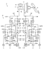
- FIG. 2 is a schematic configuration diagram illustrating an example of a braking device according to the embodiment.
- FIG. 3 is a schematic cross-sectional view illustrating an example of a control valve of the VSC actuator according to the embodiment.
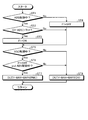
- FIG. 4 is a flowchart illustrating an example of control by the ECU according to the embodiment.
- FIG. 5 is a diagram illustrating an example of a limited control map according to the embodiment.
- FIG. 6 is a diagram illustrating an example of an unrestricted control map according to the embodiment.
- FIG. 7 is a time chart for explaining an example of control by the ECU according to the embodiment.
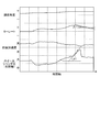
- FIG. 8 is a time chart for explaining behavior in the vehicle behavior control system according to the embodiment.
- FIG. 9 is a time chart for explaining the behavior in the vehicle behavior control system according to the comparative example.
- FIG. 1 is a schematic configuration diagram of a vehicle according to the embodiment
- FIG. 2 is a schematic configuration diagram illustrating an example of a braking device according to the embodiment
- FIG. 3 is a schematic diagram illustrating an example of a control valve of a VSC actuator according to the embodiment.
- FIG. 4 is a flowchart for explaining an example of control by the ECU according to the embodiment
- FIG. 5 is a diagram showing an example of a limited control map according to the embodiment
- FIG. 6 is no restriction according to the embodiment.
- FIG. 7 is a time chart for explaining an example of control by the ECU according to the embodiment
- FIG. 8 is a time chart for explaining behavior in the vehicle behavior control system according to the embodiment
- FIG. These are time charts explaining the behavior in the vehicle behavior control system according to the comparative example.
- the present embodiment is typically applied to a vehicle and has the following components.
- VSC actuator one that can control the wheel cylinder hydraulic pressure independently of the four wheels and has no high pressure accumulator such as an accumulator).
- An ECU that integrates and controls the above.
- Those connecting the above CAN, wire harness, etc.).
- VSC Vehicle Stability Control
- ABS Antilock Brake System
- the effect of stabilizing the behavior by the VSC control can be appropriately obtained by not limiting the pressure increase gradient of the braking hydraulic pressure.
- the mode in which the pressure increase gradient is limited even when the lateral acceleration becomes a predetermined value or less is entered when the mode in which the pressure increase gradient is not limited in the VSC control is entered. Do not return to.
- a vehicle behavior control system 1 is mounted on a vehicle 2 as shown in FIG. 1, and is a system for controlling the vehicle 2. Typically, a braking force generated on a wheel 3 of the vehicle 2 is applied. It is a system that controls the slip state of each wheel 3 and the turning state of the vehicle 2 by controlling to stabilize the behavior of the vehicle 2.
- the vehicle 2 includes a left front wheel 3FL, a right front wheel 3FR, a left rear wheel 3RL, and a right rear wheel 3RR as the wheels 3, but these are simply referred to as wheels 3 when it is not necessary to separate them.
- the vehicle behavior control system 1 includes an accelerator pedal 4, a drive source 5, a brake pedal 6, a braking device 7, an ECU 8 as a control device (vehicle control device), and the like.
- the drive source 5 generates power (torque) according to the operation of the accelerator pedal 4 by the driver, and this power is transmitted to the wheels 3 via a power transmission device (not shown). Generate driving force.
- the vehicle 2 generates a braking force on the wheel 3 by operating the braking device 7 according to the operation of the brake pedal 6 by the driver.
- the drive source 5 is a driving power source such as an internal combustion engine.
- the braking device 7 can individually adjust the braking force generated on each wheel 3 of the vehicle 2.
- the brake device 7 is a variety of hydraulic brake devices in which brake oil as working fluid is filled in a hydraulic path connected from the master cylinder 9 to the wheel cylinder 11 via the VSC actuator 10.
- the hydraulic braking unit 12 operates according to the braking pressure supplied to the wheel cylinder 11 to generate a pressure braking force on the wheel 3.
- the braking device 7 will be described in detail later.
- the ECU 8 controls driving of each part of the vehicle 2 and includes an electronic circuit mainly composed of a known microcomputer including a CPU, a ROM, a RAM, and an interface.
- the ECU 8 is generated in, for example, each wheel speed sensor 13 that detects the rotational speed of each wheel 3, a steering angle sensor 14 that detects the steering angle of the vehicle 2, a yaw rate sensor 15 that detects the yaw rate of the vehicle 2, and the vehicle body of the vehicle 2.
- Various sensors and detection devices attached to various parts of the vehicle 2 such as a lateral acceleration sensor 16 for detecting acceleration in the lateral direction (direction intersecting (orthogonal to) the traveling direction) are electrically connected, and electricity corresponding to the detection result A signal is input.
- the ECU 8 drives each part of the vehicle 2 such as the drive source 5 and the VSC actuator 10 of the braking device 7 by executing a stored control program based on various input signals and various maps input from various sensors. A signal is output to control these driving operations.
- the ECU 8 of this embodiment controls the VSC actuator 10 according to the traveling state of the vehicle 2 and individually increases or decreases the wheel cylinder pressures of the wheel cylinders 11 provided on the wheels 3, respectively.
- the ECU 8 controls, for example, ABS control for controlling the braking device 7 to control the slip state of the wheels 3, and turning for controlling the turning state of the vehicle 2 by controlling the braking device 7.
- VSC control or the like as control can be executed.
- the VSC actuator 10 provided in the braking device 7 of the present embodiment includes an accumulator or the like, and uses a hydraulic booster that uses a hydraulic pressure to amplify the pedal depression force input from the driver to the brake pedal 6. It is not a booster type hydraulic actuator, but a so-called vacuum booster type hydraulic actuator.
- This vacuum booster type VSC actuator 10 is capable of individually increasing, reducing and maintaining the wheel cylinder hydraulic pressure independently of the four wheels, and does not include a high pressure accumulating mechanism such as an accumulator.
- a vacuum booster (negative pressure assisting device) that amplifies the pedal depression force input from the driver to the brake pedal 6 using the negative pressure supplied from the internal combustion engine or the like is used.
- the braking device 7 is increased by a vacuum booster 17 as a negative pressure booster that increases the pedal depression force (operation force) input to the brake pedal 6 as a braking operation member by using negative pressure, and a vacuum booster 17.
- a master cylinder 9 that applies a master cylinder pressure (operating pressure) to brake oil (working fluid) according to the pedal depression force, and a wheel cylinder pressure (braking pressure) based on the master cylinder pressure provided on each wheel 3 acts.
- the wheel cylinder 11 that generates the braking force on each wheel 3 and the actuator that can individually adjust the braking force generated on each wheel 3 by individually adjusting the wheel cylinder pressure supplied to the wheel cylinder 11 VSC actuator 10 and calipers, brake pads, disc rotors, etc.
- a hydraulic brake unit 12 constituted in, having a reservoir 18 for storing excess brake fluid.
- the braking device 7 basically applies a master cylinder pressure to the brake oil by the master cylinder 9 according to the pedal depression force acting on the brake pedal 6 when the driver operates the brake pedal 6.
- the master cylinder pressure acts as the wheel cylinder pressure in each wheel cylinder 11, so that the hydraulic braking unit 12 is activated and generates a pressure braking force on the wheel 3.
- the brake pedal 6 is operated by the driver in response to a braking request when the driver generates a braking force on the vehicle 2.
- the master cylinder 9 pressurizes the brake oil by a piston interlocked with the brake pedal 6 when a pedal depression force is input from the driver to the brake pedal 6, and applies a master cylinder pressure corresponding to the pedal depression force. That is, the master cylinder 9 converts the pedal depression force input via the brake pedal 6 into a master cylinder pressure corresponding to the pedal depression force.
- the reservoir 18 is connected to the master cylinder 9 and stores brake oil therein. The reservoir 18 and the master cylinder 9 communicate with each other when the brake pedal 6 is not depressed. When the brake pedal 6 is depressed, the communication is cut off, and the brake oil is pressurized in the master cylinder 9.
- the vacuum booster 17 is integrally attached to the master cylinder 9 and is connected to an intake path (intake passage) of an internal combustion engine (engine) that forms the drive source 5 via a negative pressure pipe or the like, and generates negative pressure generated in the internal combustion engine. Is supplied.
- the vacuum booster 17 amplifies the pedal depression force by a force acting on a diaphragm (not shown) according to a differential pressure between a supplied negative pressure and a pressure due to outside air.
- the vacuum booster 17 increases the pedal depression force when the brake pedal 6 is braked by negative pressure, and increases the pedal depression force input to the master cylinder 9 with respect to the pedal depression force input to the brake pedal 6.
- the pedal depression force applied to the brake pedal 6 can be reduced.
- the master cylinder 9 pressurizes the brake oil according to the pedal depression force amplified by the vacuum booster 17 and applies the master cylinder pressure to the brake oil.
- the VSC actuator 10 is provided on the hydraulic path of brake oil that connects the master cylinder 9 and the wheel cylinder 11, and increases or decreases the hydraulic pressure in each wheel cylinder 11 by control by the ECU 8 separately from the brake operation of the brake pedal 6. The braking force applied to each wheel 3 is controlled.
- the VSC actuator 10 controls the wheel cylinder pressure acting on each wheel cylinder 11 according to the master cylinder pressure applied to the brake oil by the master cylinder 9, or the master cylinder pressure is applied to the brake oil by the master cylinder 9. A wheel cylinder pressure is applied to each wheel cylinder 11 regardless of whether or not it exists.
- the VSC actuator 10 is constituted by various hydraulic control devices (hydraulic control circuits) controlled by the ECU 8, for example.
- the VSC actuator 10 includes a plurality of pipes, an oil pump, a plurality of hydraulic pipes connected to each wheel cylinder 11 provided in each wheel 3, and a plurality of pressures for increasing, reducing, and holding the hydraulic pressure of each hydraulic pipe. It includes a solenoid valve.
- the VSC actuator 10 functions as a working fluid pressure adjusting unit that transmits the hydraulic pressure (master cylinder pressure) in the hydraulic piping as it is, or pressurizes and depressurizes it to each wheel cylinder 11 described later in accordance with a control command of the ECU 8.
- the VSC actuator 10 is driven by, for example, an oil pump or a predetermined electromagnetic valve in accordance with a control command from the ECU 8, so that the wheel cylinder 11 is in accordance with the operation amount (depression amount) of the brake pedal 6 by the driver. It is possible to regulate the wheel cylinder pressure acting on the cylinder.
- the VSC actuator 10 is configured to increase the wheel cylinder pressure acting on the wheel cylinder 11 by driving an oil pump or a predetermined electromagnetic valve according to a control command of the ECU 8, for example, during vehicle control to be described later. It can be operated in a holding mode in which the pressure is held almost constant, a pressure reduction mode in which pressure is reduced, and the like.
- the VSC actuator 10 can set the mode individually for each wheel cylinder 11 provided in each wheel 3 according to the traveling state of the vehicle 2 under the control of the ECU 8.
- the master cylinder 9 of the braking device 7 illustrated here includes a first master cylinder chamber 9A and a second master cylinder chamber defined by free pistons 9a urged to predetermined positions by compression coil springs on both sides thereof. 9B.
- the VSC actuator 10 includes a first hydraulic control circuit 10F for the front wheels (left front wheel 3FL, right front wheel 3FR) and a rear wheel (left rear wheel) as a circuit for transmitting the hydraulic pressure from the master cylinder 9 to each wheel cylinder 11. 3RL, right rear wheel 3RR) and a second hydraulic pressure control circuit 10R.
- the brake hydraulic control conduit 101F is connected to the first master cylinder chamber 9A
- the brake hydraulic control conduit 101R is connected to the second master cylinder chamber 9B. Connect to.
- the brake hydraulic control conduit 101F has one end connected to the first master cylinder chamber 9A, and the other end connected to one end of the brake hydraulic control conduit 102FL for the left front wheel 3FL and one end of the brake hydraulic control conduit 102FR for the right front wheel 3FR. Yes.
- the first hydraulic control circuit 10F is provided with a front-wheel control valve 103F, which is a normally-open electromagnetic on-off valve, in the middle of the brake hydraulic control conduit 101F.
- the first hydraulic control circuit 10F is a check bypass that allows only the flow of oil from the first master cylinder chamber 9A toward the brake hydraulic control conduit 102FL or the brake hydraulic control conduit 102FR to the brake hydraulic control conduit 101F on both sides of the control valve 103F.
- a conduit 104F is connected.
- the control valve 103F has a housing 103b that partitions the valve chamber 103a therein, and a valve element 103c is disposed in the valve chamber 103a so as to be capable of reciprocating.
- a portion 101FA of the brake hydraulic pressure control conduit 101F on the master cylinder 9 side is always connected to the valve chamber 103a via an internal passage 103d, and the brake hydraulic pressure control conduit 101F on the side opposite to the master cylinder 9 is connected.
- the portion 101FB is connected in communication via the internal passage 103e and the port 103f.
- the control valve 103F is provided with a solenoid 103g around the valve element 103c, and the valve element 103c is urged to a valve opening position shown in FIG. 3 by a compression coil spring 103h.
- a drive voltage is applied to the solenoid 103g, the valve element 103c is urged against the port 103f against the spring force of the compression coil spring 103h, thereby closing the port 103f.
- the solenoid 103g In the state where the control valve 103F is in the closed position, the sum of the force caused by the pressure in the portion 101FB on the opposite side of the master cylinder 9 of the brake hydraulic control conduit 101F and the spring force of the compression coil spring 103h is the solenoid 103g.
- the valve element 103c opens away from the port 103f and opens the port 103f, and the oil in the portion 101FB passes through the internal passage 103e, the port 103f, the valve chamber 103a, and the internal passage 103d, and the brake hydraulic control conduit 101F. To the portion 101FA.
- control valve 103F When the oil pressure in the portion 101FB decreases due to this oil flow, the control valve 103F has a sum of the force due to the pressure and the spring force of the compression coil spring 103h lower than the electromagnetic force due to the solenoid 103g. Element 103c closes port 103f again.
- the control valve 103F controls the pressure in the portion 101FB of the brake hydraulic pressure control conduit 101F in accordance with the voltage applied to the solenoid 103g. Therefore, the control valve 103F controls the pressure in the portion 101FB by controlling the driving voltage for the solenoid 103g. The pressure can be controlled to a desired pressure.
- the check bypass conduit 104F shown in FIG. 2 is built in the control valve 103F, and is provided in the middle of the internal passage 103i and the internal passage 103i from the valve chamber 103a to the portion 101FB. And a non-return valve 103j that allows only the flow of oil.
- the first hydraulic control circuit 10F controls the left front wheel 3FL and the right front wheel 3FR at the other ends of the brake hydraulic control conduit 102FL for the left front wheel 3FL and the brake hydraulic control conduit 102FR for the right front wheel 3FR, respectively.
- a wheel cylinder 11 for controlling power is connected.
- normally-open electromagnetic on-off valves 105FL and 105FR are provided in the middle of the brake hydraulic control conduit 102FL for the left front wheel 3FL and the brake hydraulic control conduit 102FR for the right front wheel 3FR, respectively.
- the first hydraulic control circuit 10F includes check bypass conduits 106FL that allow only the flow of oil from the wheel cylinder 11 toward the brake hydraulic control conduit 101F to the brake hydraulic control conduits 102FL and 102FR on both sides of the electromagnetic on-off valves 105FL and 105FR, respectively. 106FR is connected.
- the first hydraulic control circuit 10F is configured such that one end of an oil discharge conduit 107FL is connected to a brake hydraulic control conduit 102FL between the electromagnetic on-off valve 105FL and the corresponding wheel cylinder 11, and the wheel cylinder 11 corresponding to the electromagnetic on-off valve 105FR One end of an oil discharge conduit 107FR is connected to the brake hydraulic pressure control conduit 102FR.
- the first hydraulic control circuit 10F is provided with normally closed electromagnetic on-off valves 108FL and 108FR in the middle of oil discharge conduits 107FL and 107FR, respectively, and the other ends of the oil discharge conduits 107FL and 107FR are connected to the front wheels by a connection conduit 109F. Is connected to the buffer reservoir 110F.
- the electromagnetic on-off valves 105FL and 105FR are pressure-increasing valves for increasing or maintaining the pressure in the wheel cylinder 11, respectively.
- the electromagnetic on-off valves 108FL and 108FR are pressure-reducing valves for reducing the pressure in the wheel cylinder 11, respectively. It is. Therefore, the electromagnetic on-off valves 105FL and 108FL cooperate with each other to form an increase / decrease valve for increasing and decreasing the pressure in the wheel cylinder 11 of the left front wheel 3FL, and the electromagnetic on-off valves 105FR and 108FR are in common with each other.
- the pressure increasing / reducing valve is configured to increase and decrease the pressure in the wheel cylinder 11 of the right front wheel 3FR.
- the connecting conduit 109F is connected to the suction side of the pump 112F by a connecting conduit 111F.
- the first hydraulic control circuit 10F is provided with two check valves 113F and 114F that allow only the flow of oil from the connection conduit 109F toward the pump 112F in the middle of the connection conduit 111F.
- the discharge side of the pump 112F is connected to the brake hydraulic pressure control conduit 101F by a connection conduit 116F having a damper 115F on the way.
- a check valve 117F that allows only the flow of oil from the pump 112F to the damper 115F is provided in a connection conduit 116F between the pump 112F and the damper 115F.
- connection conduit 118F In the first hydraulic control circuit 10F, one end of a connection conduit 118F is connected to a connection conduit 111F between two check valves 113F and 114F, and the other end of the connection conduit 118F is connected to the first master cylinder chamber 9A. It is connected to a brake hydraulic pressure control conduit 101F with the control valve 103F.
- the first hydraulic control circuit 10F is provided with a normally closed electromagnetic on-off valve 119F in the middle of the connecting conduit 118F.
- the electromagnetic on-off valve 119F functions as a pump intake valve that controls communication between the brake hydraulic pressure control conduit 101F between the master cylinder 9 and the control valve 103F and the intake side of the pump 112F.
- the control valve 103F cooperates with the electromagnetic on-off valve 119F and the like, and is a wheel cylinder that is indirectly the pressure in each wheel cylinder 11 of the left and right front wheels 3FL, 3FR.
- the first braking force control means common to the left and right front wheels is configured to control the braking force of the left and right front wheels 3FL and 3FR by increasing or decreasing the pressure.
- the increase / decrease control valves such as the electromagnetic on-off valves 105FL, 105FR, 108FL, 108FR control the left and right front wheels 3FL, 3FR by increasing / decreasing the wheel cylinder pressure, which is the pressure in the wheel cylinders 11 of the left / right front wheels 3FL, 3FR, respectively.
- Second braking force control means for the left front wheel 3FL and the right front wheel 3FR for individually controlling power is configured.
- the response of the braking pressure control by the second braking force control means is higher than the response of the braking pressure control by the first braking force control means.
- the brake hydraulic control conduit 101R of the second hydraulic control circuit 10R has one end connected to the first master cylinder chamber 9B, and the other end connected to the brake hydraulic control conduit 102RL for the left rear wheel 3RL and the right hydraulic rear wheel 3RR.
- One end of the brake hydraulic pressure control conduit 102RR is connected.
- the second hydraulic control circuit 10R is provided with a rear-wheel control valve 103R that is a normally-open electromagnetic on-off valve in the middle of the brake hydraulic control conduit 101R.
- the control valve 103R has substantially the same structure as the control valve 103F for the front wheels, and controls the driving voltage for the solenoid to control the pressure (upstream pressure) in the brake hydraulic control conduit 101R downstream from the control valve 103R. ) Can be controlled to a desired pressure. Further, the second hydraulic control circuit 10R reversely allows only the oil flow from the second master cylinder chamber 9B to the brake hydraulic control conduit 102RL or the brake hydraulic control conduit 102RR to the brake hydraulic control conduit 101R on both sides of the control valve 103R. A stop bypass conduit 104R is connected.
- the second hydraulic control circuit 10R applies the braking force of the left rear wheel 3RL and the right rear wheel 3RR to the other ends of the brake hydraulic control conduit 102RL for the left rear wheel 3RL and the brake hydraulic control conduit 102RR for the right rear wheel 3RR, respectively.
- a wheel cylinder 11 to be controlled is connected.
- normally open electromagnetic on-off valves 105RL and 105RR are provided in the middle of the brake hydraulic control conduit 102RL for the left rear wheel 3RL and the brake hydraulic control conduit 102RR for the right rear wheel 3RR, respectively. Yes.
- the second hydraulic control circuit 10R includes a check bypass conduit 106RL that allows only the flow of oil from the wheel cylinder 11 toward the brake hydraulic control conduit 101R to the brake hydraulic control conduits 102RL and 102RR on both sides of the electromagnetic on-off valves 105RL and 105RR, respectively. 106RR is connected.
- An oil discharge conduit 107RL is connected to the brake hydraulic control conduit 102RL between the electromagnetic on-off valve 105RL and the corresponding wheel cylinder 11, and the second hydraulic control circuit 10R is connected to the wheel cylinder 11 corresponding to the electromagnetic on-off valve 105RR.
- One end of an oil discharge conduit 107RR is connected to the brake hydraulic pressure control conduit 102RR.
- the second hydraulic control circuit 10R is provided with normally closed solenoid valves 108RL and 108RR in the middle of the oil discharge conduits 107RL and 107RR, respectively, and the other ends of the oil discharge conduits 107RL and 107RR are connected to the rear of the connection conduit 109R. It is connected to a buffer reservoir 110R for the wheel.
- the electromagnetic on-off valves 105RL and 105RR are pressure increasing valves for increasing or maintaining the pressure in the wheel cylinder 11, respectively.
- the electromagnetic on-off valves 108RL and 108RR are pressure reducing valves for reducing the pressure in the wheel cylinder 11, respectively. It is. Therefore, the electromagnetic on-off valves 105RL and 108RL constitute a pressure increasing / reducing valve for increasing and decreasing the pressure in the wheel cylinder 11 of the left rear wheel 3RL in cooperation with each other.
- the electromagnetic on-off valves 105RR and 108RR are mutually connected.
- the pressure increasing / reducing valve is configured to increase and decrease the pressure in the wheel cylinder 11 of the right rear wheel 3RR in cooperation.
- the connecting conduit 109R is connected to the suction side of the pump 112R by the connecting conduit 111R.
- the second hydraulic control circuit 10R is provided with two check valves 113R and 114R that allow only the flow of oil from the connection conduit 109R toward the pump 112R in the middle of the connection conduit 111R.
- the discharge side of the pump 112R is connected to the brake hydraulic control conduit 101R by a connecting conduit 116R having a damper 115R on the way.
- a check valve 117R that allows only the flow of oil from the pump 112R to the damper 115R is provided in a connection conduit 116R between the pump 112R and the damper 115R.
- the pumps 112F and 112R are driven by a common electric motor not shown in FIG.
- connection conduit 118R In the second hydraulic control circuit 10R, one end of a connection conduit 118R is connected to a connection conduit 111R between two check valves 113R and 114R, and the other end of the connection conduit 118R is connected to the second master cylinder chamber 9B. It is connected to a brake hydraulic pressure control conduit 101R between the control valve 103R.
- a normally closed electromagnetic on-off valve 119R is provided in the middle of the connecting conduit 118R.
- the electromagnetic on-off valve 119R functions as a pump intake valve that controls communication between the brake hydraulic pressure control conduit 101R between the master cylinder 9 and the control valve 103R and the intake side of the pump 112R.
- the control valve 103R cooperates with the electromagnetic on-off valve 119R and the like to indirectly rotate the pressure in the wheel cylinders 11 of the left and right rear wheels 3RL and 3RR.
- a first braking force control means common to the left and right front wheels is configured to control the braking force of the left and right rear wheels 3RL and 3RR by increasing and decreasing the cylinder pressure.
- the increase / decrease control valves such as the electromagnetic on-off valves 105RL, 105RR, 108RL, 108RR, etc., respectively increase / decrease the wheel cylinder pressure, which is the pressure in the wheel cylinders 11 of the left / right rear wheels 3RL, 3RR, respectively.
- Second braking force control means for the left rear wheel 3RL and the right rear wheel 3RR for individually controlling the braking force of 3RR is configured.
- the response of the braking pressure control by the second braking force control means is higher than the response of the braking pressure control by the first braking force control means.
- the VSC actuator 10 configured as described above includes control valves 103F and 103R, electromagnetic on-off valves 105FL, 105FR, 105RL, and 105RR, electromagnetic on-off valves 108FL, 108FR, 108RL, and 108RR, and electromagnetic on-off valves 119F and 119R under the control of the ECU 8.
- the wheel cylinder pressure acting on each wheel cylinder 11 by driving the pumps 112F, 112R and the like can be adjusted independently, that is, separately.
- the control valves 103F and 103R, the electromagnetic on-off valves 105FL, 105FR, 105RL, and 105RR, the electromagnetic on-off valves 108FL, 108FR, 108RL, and 108RR, and the electromagnetic on-off valves 119F and 119R are shown in FIG. Is set to the non-control position shown in FIG.
- the VSC actuator 10 is supplied with the master cylinder pressure in the first master cylinder chamber 9A to the wheel cylinders 11 of the front wheels 3FL and 3FR, and the second master cylinder chamber 9B to the wheel cylinders 11 of the rear wheels 3RL and 3RR.
- the master cylinder pressure is supplied.
- the wheel cylinder pressure in the wheel cylinder 11 of each wheel 3 is normally increased or decreased according to the pedal depression force applied to the brake pedal 6.
- the control valves 103F and 103R are switched to the closed position, the electromagnetic on / off valves 119F and 119R are opened, and the electromagnetic on / off valves 105FL, 105FR, 105RL, and 105RR of each wheel 3 are opened and closed.
- the pumps 112F and 112R are driven while the valves 108FL, 108FR, 108RL, and 108RR are in the positions shown in FIG. 2, they are pumped up by the pumps 112F and 112R in the master cylinder 9, Are supplied with the wheel cylinder pressure pumped up by the pump 112F or the pump 112R, respectively.
- the braking device 7 controls the control valves 103F, 103R and the electromagnetic on-off valves 105FL, 105FR, 105RL of each wheel 3 regardless of the pedal pressure applied to the brake pedal 6 by the wheel cylinder pressure in the wheel cylinder 11 of each wheel 3.
- 105RR is increased or decreased by opening / closing the electromagnetic opening / closing valves 108FL, 108FR, 108RL, and 108RR.
- the wheel cylinder pressure in each wheel cylinder 11 is increased when the electromagnetic on-off valves 105FL, 105FR, 105RL, 105RR and the electromagnetic on-off valves 108FL, 108FR, 108RL, 108RR are in the non-control positions shown in FIG. (Pressure increase mode), and is held when the electromagnetic on-off valves 105FL, 105FR, 105RL, 105RR are switched to the closed position and the electromagnetic on-off valves 108FL, 108FR, 108RL, 108RR are in the non-control position shown in FIG.
- the electromagnetic on-off valves 105FL, 105FR, 105RL, and 105RR, and the electromagnetic on-off valves 108FL, 108FR, 108RL, and 108RR are depressurized (depressurization mode).
- the wheel cylinder 11 forms a hydraulic braking unit 12 together with a caliper, a brake pad, a disc rotor, and the like.
- Each hydraulic braking unit 12 has a predetermined rotational resistance force corresponding to the wheel cylinder pressure supplied to the wheel cylinder 11 against the disk rotor rotating together with the wheel 3 by pressing the brake pad against the disk rotor. Acting, it is possible to apply a braking force to the disk rotor and the wheel 3 rotating integrally therewith.
- the pedal depression force is increased by a predetermined multiple according to the negative pressure by the vacuum booster 17.
- the power ratio is doubled and transmitted to the master cylinder 9.
- the pedal depression force increased by the vacuum booster 17 and transmitted to the master cylinder 9 is converted into the master cylinder pressure in the master cylinder 9 and transmitted to the wheel cylinder 11 via the VSC actuator 10.
- the wheel cylinder pressure supplied to the wheel cylinder 11 is adjusted to a predetermined hydraulic pressure by the VSC actuator 10 and transmitted to the wheel cylinder 11.
- Each hydraulic braking unit 12 rotates the wheel 3 by applying a pressure braking torque by a frictional force by applying a predetermined wheel cylinder pressure to each wheel cylinder 11 and pressing a brake pad of the caliper against the disc rotor. You can slow down.
- the ECU 8 adjusts the braking force of the wheel 3 in the slip state when the wheel 3 slips in accordance with the depression operation (braking operation) of the brake pedal 6 by the driver as the ABS control.
- the optimum braking force according to the traveling state is applied to the wheel 3.
- the ECU 8 controls the braking force generated on the wheel 3 by adjusting the output of the driving source 5 and the wheel cylinder pressure as the braking pressure of the braking device 7, thereby controlling the slip state of the wheel 3, for example, the wheel 3. Control the slip rate.
- the slip rate of each wheel 3 is an index representing slip (slip) between the tire of the wheel 3 and the road surface, and is based on the rotational speed (wheel speed) of each wheel 3 detected by each wheel speed sensor 13 or the like. Thus, it can be calculated using various methods.
- the ECU 8 basically controls the braking force generated on the wheel 3 so that the actual slip ratio becomes the target slip ratio.
- the target slip ratio is, for example, a slip ratio in the vicinity of the peak ⁇ slip ratio at which the friction coefficient of the tire of the wheel 3 is maximum.
- the target slip ratio may have a predetermined range.
- the ECU 8 executes ABS control in order to suppress slip that may occur between the wheels 3 and the road surface when the braking device 7 is activated in response to the driver's depressing operation of the brake pedal 6 while the vehicle 2 is traveling.
- the ECU 8 starts the ABS control when the slip ratio of the wheel 3 exceeds a preset threshold value.
- the ECU 8 controls the braking force generated on the wheel 3 by adjusting the wheel cylinder pressure of the braking device 7 so that the actual slip ratio becomes the target slip ratio.
- the ECU 8 reduces the wheel cylinder pressure to reduce the braking force when the actual slip ratio becomes larger than the target slip ratio, while reducing the wheel cylinder pressure when the actual slip ratio becomes smaller than the target slip ratio. Increase the braking force by increasing the pressure.
- the ECU 8 can repeat this periodically to shorten the braking distance of the vehicle 2 while preventing brake lock and improve the behavior stability and steering performance of the vehicle.
- the ECU 8 performs VSC control (turning control) as the steering angle of the vehicle 2 detected by the steering angle sensor 14, the yaw rate of the vehicle 2 detected by the yaw rate sensor 15, and the lateral acceleration of the vehicle 2 detected by the lateral acceleration sensor 16. Based on the above, the behavior of the vehicle 2 when turning is determined. If the ECU 8 detects that an excessive yaw moment acts on the vehicle body as a result of the determination, the ECU 8 controls the excessive yaw moment to suppress the excessive yaw moment so as to perform a stable turning operation.
- VSC control turning control
- the ECU 8 controls the VSC actuator 10 of the braking device 7 to generate, for example, a required braking force for generating a yaw moment in the opposite direction to the excessive yaw moment in the vehicle body of the vehicle 2 on the front turning outer wheel.
- the wheel cylinder pressure is individually increased to increase the braking force.
- the ECU 8 of the present embodiment controls the VSC actuator 10 when the absolute value of the lateral acceleration acting on the vehicle 2 is equal to or less than a predetermined value during the operation of the ABS control and the VSC control. While restricting the increase gradient of the braking force of the wheel 3 to be controlled, the behavior of the vehicle 2 is stabilized by not restricting the increase gradient of the braking force when the absolute value of the lateral acceleration is larger than a predetermined value. I am letting.
- the increase gradient of the braking force of the wheel 3 corresponds to an increase amount (change amount) of the braking force per unit time.
- the predetermined value is arbitrarily set in advance according to the behavior stabilization effect, the control feeling of control, and the like based on the actual vehicle evaluation, and is stored in the storage unit of the ECU 8.
- the ECU 8 limits the maximum gradient of the duty value supplied to the electromagnetic on-off valves 105FL, 105FR, 105RL, and 105RR that are the pressure increasing valves of the VSC actuator 10 when limiting the increasing gradient of the braking force of the wheel 3 to be controlled such as VSC control.
- the value (DUTY-MAX) is limited to limit the increasing gradient of the wheel cylinder pressure supplied to the wheel cylinder 11 of the wheel 3 to be controlled, thereby limiting the increasing gradient of the braking force.
- the ECU 8 does not limit the increase gradient of the braking force of the wheel 3 to be controlled such as VSC control
- the maximum duty value supplied to the electromagnetic on-off valves 105FL, 105FR, 105RL, and 105RR (the pressure increase valve)
- the increasing gradient of the wheel cylinder pressure supplied to the wheel cylinder 11 of the wheel 3 to be controlled is not limited, and thus the increasing gradient of the braking force is not limited.
- the ECU 8 does not limit the increasing gradient of the braking force of the wheel 3 to be controlled unless at least one of the ABS control and the VSC control is in operation.
- the ECU 8 controls the behavior of the vehicle 2 in a state where the absolute value of the lateral acceleration is larger than a predetermined value and does not limit the increasing gradient of the braking force of the wheel 3 to be controlled, that is, ABS control or VSC.
- ABS control or VSC.
- the state where the braking force increase gradient is not limited and the state where the braking force increase gradient is not limited is continued.
- the ECU 8 then performs the lateral direction during the current ABS control. Even if the acceleration decreases, the control that does not limit the increase gradient of the braking force is continued, and the control is not shifted to the control that limits the increase gradient of the braking force of the wheel 3.
- the vehicle behavior control system 1 determines the braking force of the wheel 3 to be controlled if the absolute value of the lateral acceleration is larger than the predetermined value. Since the increase gradient is not limited, even if the ABS control is operating, the side slip can be sufficiently suppressed by the VSC control, and the behavior stabilizing effect can be sufficiently obtained. As a result, the vehicle behavior control system 1 can suppress interference between the ABS control and the VSC control, and can achieve both the behavior stabilization effect by the ABS control and the behavior stability effect by the VSC control.
- this vehicle behavior control system 1 is a vacuum booster type actuator that does not include a high pressure accumulating mechanism such as an accumulator, rather than a hydro booster type actuator provided with an accumulator or the like.
- a high pressure accumulating mechanism such as an accumulator
- hydro booster type actuator provided with an accumulator or the like.
- the vehicle behavior control system 1 is configured to control the wheel 3 to be controlled when the absolute value of the lateral acceleration is equal to or less than a predetermined value. Since the increase gradient of the braking force is limited, the operational feeling of the control can be improved. In this case, the vehicle behavior control system 1 limits the increase amount (change amount) per unit time of the wheel cylinder pressure of the wheel 3 to be controlled in a state where the absolute value of the lateral acceleration is not more than a predetermined value. Thus, even if priority is given to not giving the driver a sense of discomfort over suppressing the behavior of the vehicle 2 by operating the VSC control, the behavior change of the vehicle 2 (side slip) is still in this state. Therefore, a decrease in behavioral stability of the vehicle 2 is hardly a problem. Therefore, when the absolute value of the lateral acceleration is equal to or less than the predetermined value, the vehicle behavior control system 1 can suppress the driver from feeling uncomfortable by operating the VSC control.
- the vehicle behavior control system 1 starts the control in which the lateral acceleration becomes larger than a predetermined value during the ABS control, and once the control that does not limit the increasing gradient of the braking force of the wheel 3 is started, then, during the ABS control this time. Even if the lateral acceleration decreases, the control that does not limit the increasing gradient of the braking force is continued, for example, even when the turning direction of the vehicle 2 is changed and the direction of the lateral acceleration is changed. Further, the side slip can be sufficiently suppressed by the VSC control, and the behavior stabilizing effect can be sufficiently obtained.
- control routines are repeatedly executed at a control cycle of several ms to several tens of ms.
- the ECU 8 determines whether or not the ABS control is being performed according to the operating state of each part of the braking device 7 and the like (ST1).
- the absolute value GY-ABS of the lateral acceleration of the vehicle 2 corresponds to a predetermined value set in advance based on the detection result by the lateral acceleration sensor 16. It is determined whether or not the limit determination threshold (positive value) Th1 is greater than ST1 (ST2).
- the ECU 8 determines that the absolute value GY-ABS of the lateral acceleration of the vehicle 2 is greater than the restriction determination threshold Th1 (ST2: Yes), the ECU 8 turns on the VSC pressure increase gradient restriction release flag F1 (does not restrict the pressure increase gradient). (ST3). Thereafter, the ECU 8 determines whether or not the VSC control is being performed according to the operating state of each part such as the braking device 7 (ST5).
- the ECU 8 sets the VSC pressure increase gradient restriction release flag F1 to OFF (pressure increase gradient restriction) (ST4). Thereafter, the ECU 8 determines whether or not the VSC control is being performed according to the operating state of each part such as the braking device 7 (ST5).
- the ECU 8 determines in ST2 that the absolute value GY-ABS of the lateral acceleration of the vehicle 2 is equal to or less than the limit determination threshold Th1 (ST2: No), the VSC pressure increase gradient limit release flag F1 remains in the current state. And whether or not the VSC control is being performed is determined according to the operating state of each part such as the braking device 7 (ST5). In this case, for example, if the VSC pressure increase gradient restriction release flag F1 is ON in the previous control cycle, the ECU 8 maintains the ON state as it is.
- the ECU 8 subsequently detects the lateral acceleration during the current ABS control. Even if it becomes smaller, the VSC pressure increase gradient restriction release flag F1 can be kept ON, and control without restricting the pressure increase gradient can be continued in the following processing.
- the ECU 8 determines whether the VSC pressure increase gradient restriction release flag F1 is OFF and the ABS control is being performed (ST6). ).
- the restricted control map MAP1 according to the embodiment illustrated in FIG. 5 is displayed.
- the limited control map MAP1 illustrated in FIG. 5 is a map that determines the maximum gradient when the VSC pressure increase gradient is limited.
- the horizontal axis represents the master cylinder pressure PMC, and the vertical axis represents the maximum duty value DUTY-MAX. Show.
- This limited control map MAP1 describes the relationship between the master cylinder pressure PMC and the maximum duty value DUTY-MAX.
- the limited control map MAP1 is stored in the storage unit of the ECU 8 after the relationship between the master cylinder pressure PMC and the maximum duty value DUTY-MAX is set in advance based on actual vehicle evaluation and the like.
- the increasing gradient of the wheel cylinder pressure is limited and the increasing gradient of the braking force is limited as the maximum value DUTY-MAX of the duty value decreases.
- the ECU 8 acquires the master cylinder pressure PMC from the detection result of a sensor or the like (not shown), and calculates the maximum value DUTY-MAX from the limited control map MAP1 based on the master cylinder pressure PMC.
- the maximum duty value DUTY-MAX is illustrated as being constant with respect to the master cylinder pressure PMC, but is variable with respect to the master cylinder pressure PMC. It may be. Further, the ECU 8 calculates the maximum duty value DUTY-MAX using the limited control map MAP1 illustrated in FIG. 5, but the present embodiment is not limited to this. For example, the ECU 8 may obtain the maximum duty value DUTY-MAX based on a mathematical expression corresponding to the limited control map MAP1 illustrated in FIG. The same applies to various maps described below (the same applies to the maps described below).
- the VSC pressure increase gradient restriction release flag F1 is ON or the ABS control is not being performed in ST6.
- ST6: No for example, using the unrestricted control map MAP2 illustrated in FIG. 6, for example, the maximum value DUTY ⁇ of the duty value supplied to the electromagnetic on-off valves 105FL, 105FR, 105RL, 105RR that are the pressure increasing valves Without limiting MAX (ST8), the current control cycle is terminated, and the process proceeds to the next control cycle.
- ECU8 shall not restrict
- the unrestricted control map MAP2 is a map for determining the maximum gradient when the VSC pressure increase gradient is not limited, the horizontal axis is the control target value DS by VSC control, and the vertical axis is the duty.
- the maximum value DUTY-MAX is indicated.
- the unrestricted control map MAP2 describes the relationship between the control target value DS and the maximum duty value DUTY-MAX.
- the unrestricted control map MAP2 is stored in the storage unit of the ECU 8 after the relationship between the control target value DS and the maximum duty value DUTY-MAX is set in advance based on actual vehicle evaluation and the like.
- the duty value 100% is the maximum value DUTY-MAX, that is, the maximum value DUTY-MAX is not limited.
- the ECU 8 calculates the maximum value DUTY-MAX from the unrestricted control map MAP2 based on the control target value DS corresponding to the required braking force in VSC control.
- the maximum duty value DUTY-MAX is assumed to be constant with respect to the control target value DS, as in the restricted control map MAP1. Although shown, it may be variable with respect to the control target value DS.
- the horizontal axis represents the time axis
- the vertical axis represents the ABS control operating state
- the absolute value GY-ABS of the lateral acceleration of the vehicle 2 the ON / OFF state of the VSC pressure increase gradient restriction release flag F1
- the VSC control Operating state maximum duty value DUTY-MAX
- front turning outer wheel hydraulic pressure corresponds to the wheel cylinder pressure of the wheel cylinder 11 of the front turning outer wheel (the left front wheel 3FL or the right front wheel 3FR) to be controlled in the VSC control.
- the vehicle behavior control system 1 when the ABS control is activated at time t1, in the initial state, the absolute value GY-ABS of the lateral acceleration of the vehicle 2 is less than the limit determination threshold Th1, and the VSC pressure increase Since the gradient restriction release flag F1 is OFF, the maximum value DUTY-MAX of the duty value is restricted by the ECU 8.
- the vehicle behavior control system 1 limits the maximum duty ratio DUTY-MAX, so that the pressure increase gradient of the front turning outer wheel hydraulic pressure is limited.
- the vehicle behavior control system 1 turns on the VSC pressure increase gradient restriction release flag F1 by the ECU 8,
- the ECU 8 shifts from a state where the maximum duty value DUTY-MAX is restricted to a state where it is not restricted.
- the pressure increasing gradient of the front turning outer wheel hydraulic pressure becomes relatively large.
- the VSC control is deactivated at time t4, and thereafter, the absolute value GY-ABS of the lateral acceleration of the vehicle 2 becomes equal to or less than the limit determination threshold Th1 at time t5.
- the VSC pressure increase gradient restriction release flag F1 is kept ON.
- the ECU 8 turns off the VSC pressure increase gradient restriction release flag F1.
- FIG. 8 is a time chart for explaining an example of behavior in the vehicle behavior control system 1 that operates as described above.
- FIG. 9 is a time chart for explaining an example of the behavior in the vehicle behavior control system according to the comparative example in which the increasing gradient of the braking force of the wheel 3 to be controlled is always limited.
- the horizontal axis represents the time axis
- the vertical axis represents the steering angle
- the yaw rate represents the longitudinal acceleration
- the steering angle and yaw rate are positive (+) for left turn and negative (-) for right turn
- the wheel 3 subject to VSC control is the right front wheel.
- the vehicle behavior control system 1 does not limit the pressure increase gradient ⁇ 1 of the wheel cylinder pressure of the wheel 3 to be controlled by the VSC control, so that the pressure increase gradient ⁇ 1 is related to the comparative example.
- the pressure increase gradient ⁇ 2 of the wheel cylinder pressure can be made larger. Accordingly, the vehicle behavior control system 1 can make the yaw rate decrease gradient ⁇ 1 larger than the yaw rate decrease gradient ⁇ 2 according to the comparative example, and can sufficiently suppress the side slip by the VSC control. It can be understood that it can be obtained sufficiently.
- the braking device 7 capable of individually adjusting the braking force generated on each wheel 3 of the vehicle 2 and the slip state of the wheel 3 by controlling the braking device 7.
- ECU 8 capable of executing ABS control for controlling the vehicle and VSC control for controlling the turning state of the vehicle 2.
- the ECU 8 has an absolute value of the lateral acceleration acting on the vehicle 2 during the operation of the ABS control and the VSC control.
- the absolute value of the lateral acceleration is larger than the predetermined value
- the increase gradient of the braking force is not limited when the absolute value of the lateral acceleration is larger than the predetermined value. Therefore, the vehicle behavior control system 1 can sufficiently obtain the behavior stabilization effect by the VSC control even when the ABS control is operating, and can appropriately stabilize the behavior of the vehicle 2.
- vehicle behavior control system according to the above-described embodiment of the present invention is not limited to the above-described embodiment, and various modifications can be made within the scope described in the claims.
- control device of the vehicle behavior control system has been described as an ECU that controls each part of the vehicle.
- control device is not limited to this, and is configured separately from the ECU, for example, and is detected mutually with the ECU. It may be configured to exchange information such as signals, drive signals, and control commands.
- the electromagnetic on-off valves 105FL, 105FR, 105RL, 105RR as pressure increasing valves and the electromagnetic on-off valves 108FL, 108FR, 108RL, 108RR as pressure reducing valves cooperate with each other to correspond to each other.
- the open / close valve is configured to increase, hold, and reduce the pressure inside the valve.
- These open / close valves have a pressure increasing position, a holding position, and a pressure reducing position corresponding to the pressure increasing mode, the holding mode, and the pressure reducing mode, respectively. It may be replaced with two switching valves.
- the braking device 7 described above includes the first hydraulic control circuit 10F in which the VSC actuator 10 is a brake hydraulic system of the left front wheel 3FL and the right front wheel 3FR, and the brake hydraulic system of the left rear wheel 3RL and the right rear wheel 3RR.
- the present invention is not limited to this.
- a hydraulic control circuit that is a brake hydraulic system of the left front wheel 3FL and the right rear wheel 3RR, a right front wheel 3FR, and a left It may be configured by a hydraulic control circuit that is a brake hydraulic system of the rear wheel 3RL.
Landscapes
- Engineering & Computer Science (AREA)
- Transportation (AREA)
- Mechanical Engineering (AREA)
- Regulating Braking Force (AREA)
Abstract
L'invention concerne un système de commande de comportement de véhicule
(1) comprenant un dispositif de freinage (7) capable d'ajuster individuellement la force de freinage de chaque roue (3) du véhicule (2), et un dispositif de commande (8) capable de commander le dispositif de freinage (7), d'exécuter une commande ABS pour commander le patinage des roues (3), et d'exécuter une commande de braquage pour commander l'état de braquage du véhicule (2). Le système de commande de comportement de véhicule (1) est caractérisé en ce que lorsque qu'il exécute la commande ABS ou la commande de braquage, le dispositif de commande (8) limite le gradient d'augmentation de la force de freinage lorsque la valeur absolue de l'accélération horizontale agissant sur le véhicule (2) est inférieure ou égale à une valeur prédéfinie, et ne limite pas le gradient d'augmentation de la force de freinage lorsque la valeur absolue de l'accélération horizontale est supérieure à la valeur prédéfinie. De ce fait, le système de commande de comportement de véhicule (1) confère un effet de stabilisation du comportement d'un véhicule.
Priority Applications (1)
| Application Number | Priority Date | Filing Date | Title |
|---|---|---|---|
| PCT/JP2011/060175 WO2012147165A1 (fr) | 2011-04-26 | 2011-04-26 | Système de commande de comportement de véhicule |
Applications Claiming Priority (1)
| Application Number | Priority Date | Filing Date | Title |
|---|---|---|---|
| PCT/JP2011/060175 WO2012147165A1 (fr) | 2011-04-26 | 2011-04-26 | Système de commande de comportement de véhicule |
Publications (1)
| Publication Number | Publication Date |
|---|---|
| WO2012147165A1 true WO2012147165A1 (fr) | 2012-11-01 |
Family
ID=47071707
Family Applications (1)
| Application Number | Title | Priority Date | Filing Date |
|---|---|---|---|
| PCT/JP2011/060175 Ceased WO2012147165A1 (fr) | 2011-04-26 | 2011-04-26 | Système de commande de comportement de véhicule |
Country Status (1)
| Country | Link |
|---|---|
| WO (1) | WO2012147165A1 (fr) |
Cited By (1)
| Publication number | Priority date | Publication date | Assignee | Title |
|---|---|---|---|---|
| US10166990B2 (en) | 2016-04-19 | 2019-01-01 | Toyota Jidosha Kabushiki Kaisha | Vehicle |
Citations (3)
| Publication number | Priority date | Publication date | Assignee | Title |
|---|---|---|---|---|
| JP2005028919A (ja) * | 2003-07-08 | 2005-02-03 | Toyota Motor Corp | 車輌の挙動制御装置 |
| JP2005104339A (ja) * | 2003-09-30 | 2005-04-21 | Mitsubishi Fuso Truck & Bus Corp | 車両のロールオーバ抑制制御装置 |
| JP2010064720A (ja) * | 2008-09-12 | 2010-03-25 | Advics Co Ltd | 車両の運動制御装置 |
-
2011
- 2011-04-26 WO PCT/JP2011/060175 patent/WO2012147165A1/fr not_active Ceased
Patent Citations (3)
| Publication number | Priority date | Publication date | Assignee | Title |
|---|---|---|---|---|
| JP2005028919A (ja) * | 2003-07-08 | 2005-02-03 | Toyota Motor Corp | 車輌の挙動制御装置 |
| JP2005104339A (ja) * | 2003-09-30 | 2005-04-21 | Mitsubishi Fuso Truck & Bus Corp | 車両のロールオーバ抑制制御装置 |
| JP2010064720A (ja) * | 2008-09-12 | 2010-03-25 | Advics Co Ltd | 車両の運動制御装置 |
Cited By (1)
| Publication number | Priority date | Publication date | Assignee | Title |
|---|---|---|---|---|
| US10166990B2 (en) | 2016-04-19 | 2019-01-01 | Toyota Jidosha Kabushiki Kaisha | Vehicle |
Similar Documents
| Publication | Publication Date | Title |
|---|---|---|
| JP6849822B2 (ja) | 電動倍力装置およびブレーキ制御装置 | |
| KR101745048B1 (ko) | 자동차용 전기 유압식 제동 시스템을 제어하는 방법 및 디바이스 | |
| JP6756920B2 (ja) | 車両制動システム及び方法 | |
| EP2090482B1 (fr) | Dispositif de contrôle de la pression du liquide de freinage pour véhicule à guidon | |
| KR101726143B1 (ko) | 브레이크 제어 장치 및 브레이크 제어 방법 | |
| US9056601B2 (en) | Brake apparatus | |
| US20130192937A1 (en) | Vehicle control apparatus | |
| CN105658489A (zh) | 车辆控制装置及车辆控制系统 | |
| JP5386043B2 (ja) | 車両用ブレーキ装置及びその制御方法 | |
| WO2009106971A1 (fr) | Appareil de commande de freins | |
| JP5746773B2 (ja) | 車両用ブレーキ装置及びその制御方法 | |
| JP6623952B2 (ja) | 車両用制動装置 | |
| JP6033645B2 (ja) | ブレーキ装置 | |
| JP5673458B2 (ja) | 車両挙動制御システム | |
| KR101882340B1 (ko) | 전자식 유압 제동장치 및 그 제어방법 | |
| JP5125944B2 (ja) | ブレーキ制御装置 | |
| JP2012076572A (ja) | ブレーキ制御装置 | |
| WO2012147165A1 (fr) | Système de commande de comportement de véhicule | |
| WO2015194351A1 (fr) | Dispositif de freinage | |
| JP5821830B2 (ja) | 制動力制御装置及び制御装置 | |
| JP6409189B2 (ja) | ブレーキ制御装置 | |
| JP6497346B2 (ja) | 車両の制動制御装置 | |
| WO2017170596A1 (fr) | Dispositif de freinage pour véhicule | |
| JPH10273022A (ja) | 制動力制御装置 | |
| JP2008162562A (ja) | ブレーキ制御装置 |
Legal Events
| Date | Code | Title | Description |
|---|---|---|---|
| 121 | Ep: the epo has been informed by wipo that ep was designated in this application |
Ref document number: 11864205 Country of ref document: EP Kind code of ref document: A1 |
|
| NENP | Non-entry into the national phase |
Ref country code: DE |
|
| 122 | Ep: pct application non-entry in european phase |
Ref document number: 11864205 Country of ref document: EP Kind code of ref document: A1 |
|
| NENP | Non-entry into the national phase |
Ref country code: JP |