WO2012147221A1 - エアフレッシュナー - Google Patents
エアフレッシュナー Download PDFInfo
- Publication number
- WO2012147221A1 WO2012147221A1 PCT/JP2011/072057 JP2011072057W WO2012147221A1 WO 2012147221 A1 WO2012147221 A1 WO 2012147221A1 JP 2011072057 W JP2011072057 W JP 2011072057W WO 2012147221 A1 WO2012147221 A1 WO 2012147221A1
- Authority
- WO
- WIPO (PCT)
- Prior art keywords
- air
- nozzle
- chemical
- chemical liquid
- chemical solution
- Prior art date
- Legal status (The legal status is an assumption and is not a legal conclusion. Google has not performed a legal analysis and makes no representation as to the accuracy of the status listed.)
- Ceased
Links
Images





Classifications
-
- A—HUMAN NECESSITIES
- A61—MEDICAL OR VETERINARY SCIENCE; HYGIENE
- A61L—METHODS OR APPARATUS FOR STERILISING MATERIALS OR OBJECTS IN GENERAL; DISINFECTION, STERILISATION OR DEODORISATION OF AIR; CHEMICAL ASPECTS OF BANDAGES, DRESSINGS, ABSORBENT PADS OR SURGICAL ARTICLES; MATERIALS FOR BANDAGES, DRESSINGS, ABSORBENT PADS OR SURGICAL ARTICLES
- A61L9/00—Disinfection, sterilisation or deodorisation of air
- A61L9/14—Disinfection, sterilisation or deodorisation of air using sprayed or atomised substances including air-liquid contact processes
-
- A—HUMAN NECESSITIES
- A61—MEDICAL OR VETERINARY SCIENCE; HYGIENE
- A61L—METHODS OR APPARATUS FOR STERILISING MATERIALS OR OBJECTS IN GENERAL; DISINFECTION, STERILISATION OR DEODORISATION OF AIR; CHEMICAL ASPECTS OF BANDAGES, DRESSINGS, ABSORBENT PADS OR SURGICAL ARTICLES; MATERIALS FOR BANDAGES, DRESSINGS, ABSORBENT PADS OR SURGICAL ARTICLES
- A61L9/00—Disinfection, sterilisation or deodorisation of air
- A61L9/015—Disinfection, sterilisation or deodorisation of air using gaseous or vaporous substances, e.g. ozone
- A61L9/04—Disinfection, sterilisation or deodorisation of air using gaseous or vaporous substances, e.g. ozone using substances evaporated in the air without heating
- A61L9/12—Apparatus, e.g. holders, therefor
-
- B—PERFORMING OPERATIONS; TRANSPORTING
- B05—SPRAYING OR ATOMISING IN GENERAL; APPLYING FLUENT MATERIALS TO SURFACES, IN GENERAL
- B05B—SPRAYING APPARATUS; ATOMISING APPARATUS; NOZZLES
- B05B7/00—Spraying apparatus for discharge of liquids or other fluent materials from two or more sources, e.g. of liquid and air, of powder and gas
- B05B7/02—Spray pistols; Apparatus for discharge
- B05B7/08—Spray pistols; Apparatus for discharge with separate outlet orifices, e.g. to form parallel jets, i.e. the axis of the jets being parallel, to form intersecting jets, i.e. the axis of the jets converging but not necessarily intersecting at a point
- B05B7/0869—Spray pistols; Apparatus for discharge with separate outlet orifices, e.g. to form parallel jets, i.e. the axis of the jets being parallel, to form intersecting jets, i.e. the axis of the jets converging but not necessarily intersecting at a point the liquid or other fluent material being sucked or aspirated from an outlet orifice by another fluid, e.g. a gas, coming from another outlet orifice
Definitions
- the present invention relates to an air freshener, and more particularly to an air freshener that is installed in a space such as a toilet so that the efficacy of a chemical solution is continuously drifted.
- the air freshener is an fragrance or fragrance device that sprays a fragrance into a space, or a deodorizer or deodorizer that sprays a deodorant.
- the fragrance or deodorant is simply filled in the container.
- a fragrance device a fragrance is naturally evaporated and diffused, so that a portion with a strong fragrance or a portion with a weak fragrance can be created in the indoor space.
- the fragrance in the case of a wide space, it is difficult for the fragrance to spread uniformly throughout the space. The same is true for the deodorizer.
- the air freshener and deodorant are uniformly distributed not only in a narrow space such as a toilet in a general household but also in a large space such as a toilet in a hotel or restaurant.
- a device that can be used as a fragrance device or a deodorization device that has been devised to spread is disclosed. That is, a container filled with a liquid fragrance or the like is disposed inside a main body case having a suction port and a blower outlet, and the liquid fragrance or the like in the container is located between the air suction port and the discharge port in the main body case. It arrange
- the device that diffuses the fragrance and the deodorant disclosed in Patent Document 1 is effective in that the fragrance and the like are spread uniformly over a wide space, but the fragrance evaporated from the container Since the chemical solution is blown out to the outside by an electric fan, only the components that easily evaporate are easily consumed first. For this reason, the fragrance is often scented at the beginning of installation of the container, but there is a problem that the fragrance fades with time.
- the present invention has been made in view of the above, and is capable of stably acting the effects of chemical solutions such as fragrances and deodorants over a long period of time, and the chemical solution is distributed as uniformly as possible to a wide indoor space. It is an object of the present invention to provide an air freshener that sprays chemicals such as fragrances and deodorants that can be spread.
- the air freshener of the present invention can inject air at a chemical solution nozzle connected to a chemical solution container storing a chemical solution via a chemical solution tube and outside the discharge port of the chemical solution nozzle. And an air nozzle for diffusing the chemical liquid discharged from the chemical liquid nozzle in the form of a mist, and an air supply device for injecting air from the air nozzle.
- the air nozzle is provided outside the discharge port of the chemical solution nozzle so as to be able to inject air from a direction substantially orthogonal to the discharge direction of the chemical solution from the discharge port. It is preferable that the chemical liquid in the container is sucked and discharged from the discharge port of the chemical liquid nozzle, and the discharged chemical liquid is diffused.
- the air nozzle is arranged so that the air injection direction is in a positional relationship that is substantially orthogonal to the discharge direction of the chemical liquid from the chemical liquid nozzle. It is preferable that the air nozzle is arranged to inject air in an obliquely upward direction. The air nozzle is preferably arranged such that the air injection angle is obliquely 30 to 60 degrees above the horizontal direction. It is preferable that the air supply device has a configuration in which a driving time is controlled by a control unit. The driving time of the air supply device may be controlled based on a signal output by an illuminance sensor that detects illuminance.
- the chemical liquid discharged from the chemical liquid nozzle comes into contact with the air ejected from the air nozzle.
- This air is preferably injected obliquely upward with respect to the horizontal direction.
- the chemical liquid collides with the air ejected from the air nozzle, and the chemical liquid becomes a fine mist.
- the mist of the chemical solution is blown away by the air sprayed from the air nozzle. That is, since the chemical liquid discharged from the chemical liquid nozzle is blown away by the air outside the chemical liquid nozzle, almost all components of the chemical liquid discharged from the chemical liquid nozzle are always diffused.
- the chemical liquid is configured to collide with air outside the chemical liquid nozzle, the chemical liquid mist becomes extremely fine and can be floated in the air for a long time, so that the effectiveness of the chemical liquid is prolonged in a wide area.
- the air nozzle has its air injection angle inclined at an angle of 30 ° to 60 ° with respect to the horizontal direction, so that the mist of the chemical solution can be further diffused and diffused in the air.
- the control unit can automatically spray the chemical liquid at a predetermined time, for example, by setting the time of air injection with a timer. Furthermore, since there is almost no use at night in department store toilets, etc., by providing an illuminance sensor, it is configured to stop the air injection drive when it gets dark, and drive when it becomes brighter than the predetermined, Waste of chemicals can be eliminated.
- FIG. 1 is a diagram for explaining a configuration of a main part including a nozzle part in an air freshener according to an embodiment of the present invention.
- FIG. 2 is a diagram illustrating an internal configuration of the air freshener according to the embodiment.
- FIG. 3 is a diagram showing an internal configuration of the air freshener according to the embodiment, and shows an arrangement relationship between an air nozzle and a chemical nozzle, a chemical solution container, a chemical solution tube, a compressor, an air tube, and a control unit constituting the nozzle unit. It is a figure.
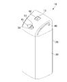
- FIG. 4 is a perspective view showing the appearance of the air freshener according to the embodiment.
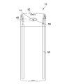
- FIG. 5 is a front view showing the appearance of the air freshener of the embodiment.
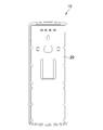
- FIG. 6 is a rear view showing the appearance of the air freshener of the embodiment.
- FIG. 7 is a plan view showing the appearance of the air freshener according to the embodiment.
- FIG. 8 is a bottom view showing the appearance of the air freshener of the embodiment.
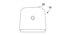
- FIG. 9 is a left side view showing the appearance of the air freshener of the above embodiment.
- FIG. 10 is a right side view showing the appearance of the air freshener of the embodiment.
- FIG. 11 is a view for explaining a configuration of a main part including a nozzle part in an air freshener according to another embodiment of the present invention.
- the air freshener 10 has a substantially box shape with a back cover 20, a lower cover 30, and an upper cover 40 located on the back side.
- two batteries 11 serving as a power source
- a chemical solution container 12 enclosing a chemical solution LM such as a liquid fragrance or deodorant
- a nozzle unit 50 for spraying the chemical solution LM Etc.
- the back cover 20 is provided with a nozzle support member 21 for supporting the nozzle portion 50 at the upper portion thereof, and the chemical solution container 12 is disposed below the nozzle support member 21.
- a supporting upper shelf 22 is provided.
- a battery box 23 is provided below the upper shelf 22, and the battery 11 is placed in the battery box 23.
- a compressor 54 is disposed near the back cover 20 in a range surrounded by the battery box 23. It should be noted that these arrangements are merely examples and are not limited to those shown in the drawings.
- the lower cover 30 covers the front surface and both side surfaces of the upper shelf 22 and the battery box 23 supported by the back cover 20 in a state where the chemical container 12 and the battery 11 are disposed as described above. Is detachably provided.
- the upper cover 40 covers the upper side of the lower cover 30 and is detachably provided on the back cover 20 and the lower cover 30.
- the upper cover 40 is formed to bend so as to be inclined downward from the rear to the front when viewed from the side (see FIGS. 9 and 10), and the nozzle portion 50 is formed on the front wall.
- medical solution sprayed from to pass through and spraying outside is formed.
- a control board constituting the control unit 70 and an illuminance sensor 13 for detecting ambient illuminance are attached inside the upper cover 40.
- the illuminance sensor 13 is electrically connected to the control unit 70 as shown in FIG.
- An illuminance sensor window 42 facing the illuminance sensor 13 is formed near the rear of the upper wall of the upper cover 40.
- the nozzle unit 50 that forms the main part of the present embodiment will be described in detail.
- the nozzle unit 50 includes an air nozzle 51 that ejects air in an obliquely upward direction, and a chemical liquid nozzle 55 that discharges the chemical liquid LM, and the front wall of the upper cover 40 as described above. It faces the spray port 41 formed in the above.
- the air nozzle 51 and the chemical liquid nozzle 55 are arranged such that the arrangement directions along the respective axes are substantially orthogonal.
- the air sprayed from the air nozzle 51 is disposed so as to pass through the vicinity of the discharge port 55 a of the chemical liquid nozzle 55. More specifically, although it is outside the discharge port 55a of the chemical liquid nozzle 55, the air injection port 51a of the air nozzle 51 is disposed close to the discharge port 55a.
- the air nozzle 51 communicates with an air supply device 53 via an air tube 52 (air supply pipe).
- the air supply device 53 includes a compressor 54, and passes necessary air (compressed air) through the air tube 52 through a control valve mechanism (not shown) incorporated as necessary. Supply.
- the compressor 54 constituting the air supply device 53 is electrically connected to the control unit 70 and is driven in response to a control signal from the control unit 70.
- the air nozzle 51 has its air injection angle ⁇ directed obliquely upward by 30 ° to 60 ° with respect to the horizontal direction, so that the mist-like chemical liquid (mist M) is moved further into the air. It is preferable in terms of In particular, it is desirable to set to 35 to 55 degrees, and further to 45 degrees.
- the air nozzle 51 and the chemical solution nozzle 55 are arranged so as to face the spray port 41 formed in the upper cover 40.
- the spray port 41 is provided so as to open in the air injection direction of the air nozzle 51. is there.
- the chemical nozzle 55 is connected to one end of a chemical tube 58 (chemical solution supply pipe).
- the other end of the chemical liquid tube 58 is inserted into the chemical liquid container 12 and is in contact with the chemical liquid LM.
- the chemical liquid LM as described above, a fragrance or a deodorant is used.
- the discharge port 55a of the chemical liquid nozzle 55 is close to the air injection port 51a of the air nozzle 51 as described above.
- the air passes so as to be substantially perpendicular to the discharge direction, that is, across the discharge direction. Accordingly, the vicinity of the discharge port 55 a of the chemical liquid nozzle 55 becomes negative pressure, and the chemical liquid LM in the chemical liquid container 12 is sucked through the chemical liquid tube 58 and discharged from the discharge port 55 a at the tip of the chemical liquid nozzle 55.
- the chemical liquid LM is discharged to the outside from the chemical liquid nozzle 55, and at the same time, the air injected from the air nozzle 51 that passes immediately before the discharge port 55a collides.
- the chemical liquid LM is mist-like, preferably fined to 30 ⁇ m or less, and at the same time, the chemical liquid LM is blown out through the spray port 41 of the upper cover 40 according to the air pressure ejected from the air nozzle 51. Diffused.
- the chemical solution mist M is further refined.
- the chemical liquid LM is forcibly sucked and blown out from the chemical liquid container 12 through the chemical liquid tube 58 when air (compressed air) passes outside the vicinity of the discharge port 55a of the chemical liquid nozzle 55. Therefore, it is less likely that only a specific component in the chemical liquid LM is diffused as in the prior art, and a desired chemical effect can be stably exhibited over a longer period of time.
- the sprayed mist M of the medicinal solution is refined and blown away, it will float in the air for a long time. Can be spread evenly.
- control unit 70 is configured to automatically spray when a predetermined time is reached, for example, by setting a driving time for spraying the chemical liquid LM with a timer.
- a predetermined time for example, by setting a driving time for spraying the chemical liquid LM with a timer.
- the air freshener 10 of the present embodiment is installed in, for example, a public toilet, it is not necessary to spray in a time zone that is not used by a person. Therefore, by providing the illuminance sensor 13 as described above, it is possible to reduce the waste of the chemical solution by adopting a configuration in which the spray driving is stopped when it becomes dark and the spray driving is performed when the brightness becomes a predetermined brightness or more.
- FIG. 11 is a diagram showing a schematic configuration of another embodiment of the present invention.
- the same members as those in the above embodiment are indicated by the same reference numerals.
- This embodiment is different from the above embodiment in that a chemical liquid supply device 59 is interposed between the chemical liquid container 12 and the chemical liquid tube 58 (chemical liquid supply pipe).
- the chemical liquid supply device 59 includes a chemical liquid pump 61 that supplies the chemical liquid LM in the chemical liquid container 12, and the necessary chemical liquid LM is discharged through the chemical liquid tube 58 by driving the chemical liquid pump 61.
- the chemical pump 61 is driven by a motor 62, and the motor 62 is connected to the control unit 70.
- the chemical liquid LM is forcibly discharged from the discharge port 55 a at the tip of the chemical liquid nozzle 55 by driving the chemical liquid supply device 59.
- the air jetted from the air nozzle 51 collides with the chemical liquid LM discharged from the chemical nozzle 55 to the outside.
- the chemical liquid LM is in a mist shape, and is preferably miniaturized to 30 ⁇ m or less.
- the atomized mist M of the chemical liquid passes through the spray port 41 of the upper cover 40 according to the air pressure ejected from the air nozzle 51 and is blown off and diffused.
- the discharge of the chemical liquid LM from the chemical liquid nozzle 55 has a simple structure, as in the above-described embodiment, forcibly sucked by setting the vicinity of the discharge port 55a of the chemical liquid nozzle 55 to a negative pressure. Therefore, it is preferable.
- the compressor 54 that is, the pressure of the air jetted from the air nozzle 51, a configuration using the chemical pump 61 as shown in FIG.
Landscapes
- Health & Medical Sciences (AREA)
- Epidemiology (AREA)
- Life Sciences & Earth Sciences (AREA)
- Animal Behavior & Ethology (AREA)
- General Health & Medical Sciences (AREA)
- Public Health (AREA)
- Veterinary Medicine (AREA)
- Disinfection, Sterilisation Or Deodorisation Of Air (AREA)
- Nozzles (AREA)
Abstract
Description
前記エアノズルは、前記薬液ノズルの吐出口の外部であって、この吐出口からの薬液の吐出方向に対して略直交する方向からエアを噴射可能に設けられ、エアを噴射することにより、前記薬液容器の薬液を吸引して前記薬液ノズルの吐出口から吐出させると共に、吐出した薬液を拡散させる構成であることが好ましい。
前記エアノズルは、エアの噴射方向が、前記薬液ノズルからの薬液の吐出方向と略直交する位置関係となるように配置されていることが好ましい。
前記エアノズルが斜め上方向に向けてエアを噴射するように配置されていることが好ましい。前記エアノズルは、そのエア噴射角度が水平方向に対して30度~60度斜め上となるように配置されていることが好ましい。前記エア供給装置は、制御部によって駆動時間が制御される構成であることが好ましい。前記エア供給装置の駆動時間は、照度を検出する照度センサによって出力される信号に基づいて制御される構成とすることもできる。
本実施形態に係るエアフレッシュナー10は、図2に示すように、背側に位置する背部カバー20と、下カバー30と、上カバー40とで略箱型形状をなしている。その略箱型形状の内部に収納されるものとして、電源となる2個の電池11、液状の芳香剤や消臭剤などの薬液LMを封入した薬液容器12、薬液LMを噴霧するノズル部50等を備える。
エアノズル51には、エア供給装置53のコンプレッサ54が駆動することにより、エア(圧縮空気)が送り込まれ、水平方向に対して斜め上に向けたエア噴射角度θにてエア(圧縮空気)が噴射される。なお、本実施形態のように照度センサ13を設けている場合には、所定の明るさになっとことを照度センサ13が検知すると、制御部70から制御信号が送られてコンプレッサ54が駆動する。
11 電池
12 薬液容器
13 照度センサ
20 背部カバー
30 下カバー
40 上カバー
41 噴霧口
42 照度センサ窓
50 ノズル部
51 エアノズル
52 エアチューブ
53 エア供給装置
54 コンプレッサ
55 薬液ノズル
58 薬液チューブ
70 制御部
Claims (8)
- 薬液が貯留された薬液容器に薬液チューブを介して接続された薬液ノズルと、
前記薬液ノズルの吐出口の外部にて、エアを噴射可能に設けられ、前記薬液ノズルから吐出される薬液をミスト状で拡散させるエアノズルと、
前記エアノズルからエアを噴射させるエア供給装置と
を有することを特徴とするエアフレッシュナー。 - 前記エアノズルは、前記薬液ノズルの吐出口の外部であって、この吐出口からの薬液の吐出方向に対して略直交する方向からエアを噴射可能に設けられ、エアを噴射することにより、前記薬液容器の薬液を吸引して前記薬液ノズルの吐出口から吐出させると共に、吐出した薬液を拡散させる構成である請求項1記載のエアフレッシュナー。
- さらに、薬液供給装置を有し、この薬液供給装置により、前記薬液容器に貯留された薬液が前記薬液ノズルに供給され、その吐出口から薬液が吐出される構成である請求項1記載のエアフレッシュナー。
- 前記エアノズルは、エアの噴射方向が、前記薬液ノズルからの薬液の吐出方向と略直交する位置関係となるように配置されている請求項1~3のいずれか1に記載のエアフレッシュナー。
- 前記エアノズルが斜め上方向に向けてエアを噴射するように配置されている請求項1~4のいずれか1に記載のエアフレッシュナー。
- 前記エアノズルは、そのエア噴射角度が水平方向に対して30度~60度斜め上となるように配置されている請求項5記載のエアフレッシュナー。
- 前記エア供給装置は、制御部によって駆動時間が制御される構成である請求項1~6のいずれか1に記載のエアフレッシュナー。
- 前記エア供給装置の駆動時間は、照度を検出する照度センサによって出力される信号に基づいて制御される請求項7記載のエアフレッシュナー。
Priority Applications (4)
| Application Number | Priority Date | Filing Date | Title |
|---|---|---|---|
| JP2013511865A JPWO2012147221A1 (ja) | 2011-04-28 | 2011-09-27 | エアフレッシュナー |
| CN201190001101.0U CN203777368U (zh) | 2011-04-28 | 2011-09-27 | 空气清新器 |
| PH1/2013/502428A PH12013502428A1 (en) | 2011-04-28 | 2011-09-27 | Air freshener |
| PH22013500006U PH22013500006U1 (en) | 2011-04-28 | 2013-11-22 | Air freshener |
Applications Claiming Priority (2)
| Application Number | Priority Date | Filing Date | Title |
|---|---|---|---|
| JP2011-101769 | 2011-04-28 | ||
| JP2011101769 | 2011-04-28 |
Publications (1)
| Publication Number | Publication Date |
|---|---|
| WO2012147221A1 true WO2012147221A1 (ja) | 2012-11-01 |
Family
ID=47071760
Family Applications (1)
| Application Number | Title | Priority Date | Filing Date |
|---|---|---|---|
| PCT/JP2011/072057 Ceased WO2012147221A1 (ja) | 2011-04-28 | 2011-09-27 | エアフレッシュナー |
Country Status (5)
| Country | Link |
|---|---|
| JP (2) | JPWO2012147221A1 (ja) |
| CN (1) | CN203777368U (ja) |
| HK (1) | HK1198498A2 (ja) |
| PH (2) | PH12013502428A1 (ja) |
| WO (1) | WO2012147221A1 (ja) |
Cited By (3)
| Publication number | Priority date | Publication date | Assignee | Title |
|---|---|---|---|---|
| JP2015073873A (ja) * | 2013-10-12 | 2015-04-20 | 東邦インターナショナル株式会社 | 小型液体噴霧装置 |
| JP2019503272A (ja) * | 2016-01-28 | 2019-02-07 | ゲルパス ゲーエムベーハー | 噴霧可能な流体を噴霧するための分注装置 |
| WO2021019872A1 (ja) * | 2019-07-30 | 2021-02-04 | 共立製薬株式会社 | 液体噴霧装置 |
Families Citing this family (4)
| Publication number | Priority date | Publication date | Assignee | Title |
|---|---|---|---|---|
| CN104353572A (zh) * | 2014-10-17 | 2015-02-18 | 南开大学 | 一种无运动部件实现大面积均匀镀膜的装置 |
| CH713113A1 (de) * | 2016-11-08 | 2018-05-15 | Chemspeed Tech Ag | Sprühverfahren zur Beschichtung eines Substrats mit einer in einem Gasstrom zerstäubten Substanz. |
| JP2019072363A (ja) * | 2017-10-18 | 2019-05-16 | キヤノンマーケティングジャパン株式会社 | 洗浄システム及び洗浄方法、並びに、情報処理装置、その制御方法、及びプログラム |
| WO2020257186A1 (en) * | 2019-06-17 | 2020-12-24 | Oms Investments, Inc. | Mist sprayer apparatus |
Citations (2)
| Publication number | Priority date | Publication date | Assignee | Title |
|---|---|---|---|---|
| JPH0475546U (ja) * | 1990-11-16 | 1992-07-01 | ||
| JP2003339843A (ja) * | 2002-05-24 | 2003-12-02 | Nagata:Kk | 消臭機 |
-
2011
- 2011-09-27 CN CN201190001101.0U patent/CN203777368U/zh not_active Expired - Lifetime
- 2011-09-27 WO PCT/JP2011/072057 patent/WO2012147221A1/ja not_active Ceased
- 2011-09-27 JP JP2013511865A patent/JPWO2012147221A1/ja active Pending
- 2011-09-27 PH PH1/2013/502428A patent/PH12013502428A1/en unknown
- 2011-09-27 HK HK14102574.4A patent/HK1198498A2/zh not_active IP Right Cessation
-
2013
- 2013-11-22 PH PH22013500006U patent/PH22013500006U1/en unknown
-
2015
- 2015-09-29 JP JP2015004953U patent/JP3201503U/ja not_active Expired - Lifetime
Patent Citations (2)
| Publication number | Priority date | Publication date | Assignee | Title |
|---|---|---|---|---|
| JPH0475546U (ja) * | 1990-11-16 | 1992-07-01 | ||
| JP2003339843A (ja) * | 2002-05-24 | 2003-12-02 | Nagata:Kk | 消臭機 |
Cited By (5)
| Publication number | Priority date | Publication date | Assignee | Title |
|---|---|---|---|---|
| JP2015073873A (ja) * | 2013-10-12 | 2015-04-20 | 東邦インターナショナル株式会社 | 小型液体噴霧装置 |
| JP2019503272A (ja) * | 2016-01-28 | 2019-02-07 | ゲルパス ゲーエムベーハー | 噴霧可能な流体を噴霧するための分注装置 |
| WO2021019872A1 (ja) * | 2019-07-30 | 2021-02-04 | 共立製薬株式会社 | 液体噴霧装置 |
| JP2021020195A (ja) * | 2019-07-30 | 2021-02-18 | 共立製薬株式会社 | 液体噴霧装置 |
| JP7170993B2 (ja) | 2019-07-30 | 2022-11-15 | 共立製薬株式会社 | 液体噴霧装置 |
Also Published As
| Publication number | Publication date |
|---|---|
| HK1198498A2 (zh) | 2015-05-08 |
| CN203777368U (zh) | 2014-08-20 |
| JPWO2012147221A1 (ja) | 2014-07-28 |
| PH22013500006U1 (en) | 2016-10-28 |
| JP3201503U (ja) | 2015-12-10 |
| PH12013502428A1 (en) | 2014-01-13 |
Similar Documents
| Publication | Publication Date | Title |
|---|---|---|
| JP3201503U (ja) | エアフレッシュナー | |
| JP2014057952A (ja) | 霧発生装置 | |
| JP5819560B1 (ja) | 微粒化した液体にマイナスの電荷を帯びさせ放出する装置 | |
| EP1689603B1 (en) | A mist-spraying apparatus | |
| JP2018086634A (ja) | 液体噴霧装置 | |
| JP2019130030A (ja) | アロマディフューザ | |
| WO2019133104A1 (en) | Wall mountable essential oil diffuser | |
| JP3171940U (ja) | 消毒液噴霧器 | |
| JP7170993B2 (ja) | 液体噴霧装置 | |
| KR100896433B1 (ko) | 방취제 분무장치 | |
| KR200459540Y1 (ko) | 가습 겸용 산소발생장치 | |
| KR101235695B1 (ko) | 휘산장치 | |
| JP2009072653A (ja) | 超音波霧化装置 | |
| JPH11514247A (ja) | 流体物を使う燻蒸装置 | |
| CN100420523C (zh) | 喷雾装置 | |
| RU183064U1 (ru) | Увлажнитель воздуха | |
| KR20220153916A (ko) | 자동 분무 장치 및 이를 구비하는 차량용 공조 장치 | |
| KR200419105Y1 (ko) | 탈취장치 | |
| KR200316874Y1 (ko) | 미립자 분무장치 | |
| KR200207346Y1 (ko) | 향분사기를 가진 벽체형 가습기 | |
| KR20080003137U (ko) | 이동식 연무장치 | |
| US8790590B1 (en) | Air treatment substance delivery apparatus for air conditioning systems | |
| KR20160093209A (ko) | 방향제 휘산장치 | |
| JPH06237983A (ja) | 消臭剤等の多目的ミスト送出装置 | |
| HK40070144A (en) | Liquid spray device |
Legal Events
| Date | Code | Title | Description |
|---|---|---|---|
| WWE | Wipo information: entry into national phase |
Ref document number: 201190001101.0 Country of ref document: CN |
|
| 121 | Ep: the epo has been informed by wipo that ep was designated in this application |
Ref document number: 11864183 Country of ref document: EP Kind code of ref document: A1 |
|
| ENP | Entry into the national phase |
Ref document number: 2013511865 Country of ref document: JP Kind code of ref document: A |
|
| NENP | Non-entry into the national phase |
Ref country code: DE |
|
| 122 | Ep: pct application non-entry in european phase |
Ref document number: 11864183 Country of ref document: EP Kind code of ref document: A1 |