WO2012147345A1 - Machine tire-lait - Google Patents
Machine tire-lait Download PDFInfo
- Publication number
- WO2012147345A1 WO2012147345A1 PCT/JP2012/002844 JP2012002844W WO2012147345A1 WO 2012147345 A1 WO2012147345 A1 WO 2012147345A1 JP 2012002844 W JP2012002844 W JP 2012002844W WO 2012147345 A1 WO2012147345 A1 WO 2012147345A1
- Authority
- WO
- WIPO (PCT)
- Prior art keywords
- breast
- milking
- contact
- areola
- user
- Prior art date
- Legal status (The legal status is an assumption and is not a legal conclusion. Google has not performed a legal analysis and makes no representation as to the accuracy of the status listed.)
- Ceased
Links
Images


Classifications
-
- A—HUMAN NECESSITIES
- A61—MEDICAL OR VETERINARY SCIENCE; HYGIENE
- A61M—DEVICES FOR INTRODUCING MEDIA INTO, OR ONTO, THE BODY; DEVICES FOR TRANSDUCING BODY MEDIA OR FOR TAKING MEDIA FROM THE BODY; DEVICES FOR PRODUCING OR ENDING SLEEP OR STUPOR
- A61M1/00—Suction or pumping devices for medical purposes; Devices for carrying-off, for treatment of, or for carrying-over, body-liquids; Drainage systems
- A61M1/06—Milking pumps
- A61M1/062—Pump accessories
- A61M1/064—Suction cups
- A61M1/066—Inserts therefor
-
- A—HUMAN NECESSITIES
- A61—MEDICAL OR VETERINARY SCIENCE; HYGIENE
- A61M—DEVICES FOR INTRODUCING MEDIA INTO, OR ONTO, THE BODY; DEVICES FOR TRANSDUCING BODY MEDIA OR FOR TAKING MEDIA FROM THE BODY; DEVICES FOR PRODUCING OR ENDING SLEEP OR STUPOR
- A61M1/00—Suction or pumping devices for medical purposes; Devices for carrying-off, for treatment of, or for carrying-over, body-liquids; Drainage systems
- A61M1/06—Milking pumps
-
- A—HUMAN NECESSITIES
- A61—MEDICAL OR VETERINARY SCIENCE; HYGIENE
- A61M—DEVICES FOR INTRODUCING MEDIA INTO, OR ONTO, THE BODY; DEVICES FOR TRANSDUCING BODY MEDIA OR FOR TAKING MEDIA FROM THE BODY; DEVICES FOR PRODUCING OR ENDING SLEEP OR STUPOR
- A61M1/00—Suction or pumping devices for medical purposes; Devices for carrying-off, for treatment of, or for carrying-over, body-liquids; Drainage systems
- A61M1/80—Suction pumps
- A61M1/82—Membrane pumps, e.g. bulbs
Definitions
- the present invention relates to an improvement of a breast pump that generates negative pressure for milking and sucks a user's breast milk.
- a milking device having a milking part expanded in a trumpet shape that comes into contact with a mother's breast, that is, a milking enlarged part is widely used.
- a recess is provided in the upper end of the breast pump body, and a member such as a diaphragm is deformed in the recess. Contained configurations are known.
- a manual breast pump in which an operating part such as a handle is connected to the diaphragm and a negative pressure is generated by repeatedly pulling up the diaphragm by reciprocating movement of the handle.
- an operating part such as a handle
- a negative pressure is generated by repeatedly pulling up the diaphragm by reciprocating movement of the handle.
- the breast pump disclosed in Patent Document 1 is designed to prevent the operation unit from being easily detached during operation while being easily disassembled and assembled for cleaning.
- the buffer part 28 which consists of an elastic body is attached to this milking machine so that attachment or detachment is possible inside the trumpet-shaped milking enlarged diameter part 22.
- FIG. This buffering part 28 reduces the irritation
- the conventional buffer portion has a trumpet-shaped milking enlarged diameter portion formed of a hard synthetic resin or the like, and therefore is interposed between the user's breast during milking and gives unpleasant irritation and pain. It could hardly play an active role beyond prevention.
- breast pump users have various breast sizes and shapes. For this reason, there is a problem that breast milk leaks from the milking part during milking due to the shape of the breast. Moreover, since the device of physical action other than the suction
- FIG. 13 a configuration as shown in FIG. 13 is also conceivable.
- the symbol B is the main body portion (tuft portion) of the breast
- the symbol K indicates the nipple.
- the case where the user with a big breast uses a breast pump is shown.
- the breast B is received by the trumpet-shaped milking enlarged diameter portion 1, and breast milk is sucked by the negative pressure in the milking enlarged diameter portion 1 during milking.
- the above-described problem that is, the milking enlarged portion 1 is formed of a hard synthetic resin or the like, and the milking enlarged portion is prevented in order to prevent unpleasant irritation and pain on the user's breast.
- a buffer cover 2 made of a soft synthetic resin or a rubber material is provided over a wide range from the opening of 1 to the entire inner surface.
- a through-hole 5 is provided at the center of the buffer cover 2, the nipple K enters the through-hole 5, and the breast milk is guided into the milking enlarged diameter portion 1 and sent to a bottle or the like that is a storage portion (not shown). It is like that.
- the buffer unit 2 has the breast body B from the user's areolae portion in a state where the breast body B of the user is in contact with the milking diameter-expanded portion 1 at the center.
- reference numeral 3 it is in close contact with a wide range or region.
- the present invention has been made to solve the above-described problems, and in particular, can effectively prevent breast milk from leaking from the milking part that has been expanded in milking or causing a loss of negative pressure due to leakage.
- An object of the present invention is to provide a breast pump that does not give unpleasant stimuli or pain to the body.
- the present invention is provided in a storage container for storing breast milk, a breast pump body that is attached to and detached from the storage container and generates negative pressure for milking, and the breast pump body.
- the expanded milking diameter-enlarged portion to be brought into contact with the user's breast, and is used by forming a substantially circular trumpet shape along the opening of the expanded milking-diameter portion.
- a buffer portion at least partially abutting against the breast of the person is detachably disposed on the milking enlarged diameter portion, and the buffer portion is arranged at the central portion of the milking enlarged diameter portion of the user.
- the areola contact portion that contacts the concentric circle, and the concentric shape provided on the outer side of the areola contact portion A protrusion, characterized in that it comprises a breast close contact portion in close contact with the user's breast.
- the areola contact portion hits the areola portion at the tip of the breast, and in addition to sucking out the breast milk by the suction force due to the negative pressure, the areola contact portion causes the areola portion to By pushing effectively, it makes breast milk easy to come out.
- the breast contact part closely contacts the breast part, that is, the area located outside the breast areola other than the breast areola, and seals it, thereby causing negative pressure leakage. In addition to preventing, leakage of breast milk to the outside can be effectively prevented.
- the buffer portion has a substantially elliptical trumpet shape along the opening of the milking enlarged diameter portion.
- the area of close contact along the vertical direction is increased, so that the close contact degree is improved and leakage of breast milk can be effectively prevented.
- the buffer portion is provided with a cover portion that extends outward along at least a lower outer edge portion thereof.
- a cover portion that extends outward along at least a lower outer edge portion thereof.
- the buffer portion is provided with a cover portion extending in a ring shape along an outer edge portion thereof.
- a cover portion extending in a ring shape along an outer edge portion thereof.
- the areola contact portion is formed of protrusions that are in contact with a plurality of locations of the user's areola in the vicinity of the through hole and outside thereof.
- the abutment contact portion does not protrude in a ring shape in the vicinity of the through-hole, but is formed as a protrusion protruding at a plurality of locations. Since the areola part can be surely pressed at a plurality of locations, it is possible to effectively give a stimulus for improving the milk output.
- FIG. 1 is a schematic sectional view of a breast pump according to an embodiment of the present invention.
- the disassembled perspective view which shows the structure of the upper part of the milking machine of FIG.
- the side view which shows 1st Embodiment of the buffer part attached to or detached from each milk enlarged diameter part of the breast pump of FIG.
- the expansion longitudinal cross-sectional view which shows the relationship between the buffer part of FIG. 3 at the time of milking, a user's breast, and areola part vicinity.
- the schematic front view of the buffer part of FIG. The schematic front view which shows 2nd Embodiment of the buffer part of FIG.
- the figure which shows schematically the size of the magnitude
- the expansion longitudinal cross-sectional view which shows the relationship between the buffer part at the time of milking, a user's breast, and the areola part vicinity about the buffer part of FIG.
- the expanded longitudinal cross-sectional view which shows a mode that 2nd Embodiment is utilized corresponding to the magnitude
- the expanded longitudinal cross-sectional view which shows a mode that 2nd Embodiment is utilized corresponding to the magnitude
- the schematic perspective view which shows 3rd Embodiment of the buffer part of FIG.
- the expansion longitudinal cross-sectional view which shows the relationship between the buffer part at the time of milking, a user's breast, and the areola part vicinity about 3rd Embodiment shown in FIG.
- Explanatory drawing which shows the example of a form in case the buffer cover provided in the milking diameter-expanded part has a bad influence on a user.
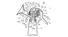
- FIG. 1 and 2 show the overall schematic configuration common to the embodiments of the present invention.
- FIG. 1 is a schematic sectional view of the embodiment
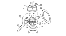
- FIG. 2 is an exploded perspective view of a part thereof.
- the structure of the buffer portion is shown for reference, and is shown in detail in other drawings.
- a breast pump 20 includes a breast pump main body 21 (hereinafter referred to as “main body”), a handle 61 that is an operation means, and a bottle 11 as a storage container for storing milked breast milk. ing.
- the handle 61 can be attached to and detached from the breast pump main body 21.
- a substantially dome-shaped hood 15 is attached to and detached from an upper portion of the main body 21 where the negative pressure generating member 30 is mounted.
- the hood 15 has a handle 61 cut off, and is attached to avoid the handle 61 to cover and protect the negative pressure generating member 30 and the like. Can be done. Note that the hood 15 may be omitted.
- the negative pressure is manually formed. However, as widely practiced, the negative pressure may be formed using an electric motor or the like.
- the entire body 21 is formed of a relatively light and strong synthetic resin material, and is formed of, for example, polypropylene, polycarbonate, polycycloolefin, polyethersulfone, polyphenylsulfone, or the like.
- the main body 21 includes an attachment / detachment portion 25 that attaches / detaches to / from the bottle 11.
- the detachable portion 25 is a flat cylindrical portion, and has a female screw portion 25 a inside, and is a male screw formed around the bottle mouth of the bottle 11. It is designed to be screwed with the part.
- the bottle 11 may be a dedicated product for the breast pump 20, a baby bottle suitable for the attachment / detachment unit 25, or the like, or may be a bag shape instead of a molded container.
- a conical or trumpet-shaped milking diameter-enlarged portion 22 is provided on the upper portion of the detachable portion 25 of the main body 21 while the tip is enlarged in a slanted state.
- a buffer part 70 made of an elastic body is detachably attached to the opening side of the milking enlarged diameter part 22.
- the buffer part 70 reduces the irritation
- the milking part air passage 23 of the milking diameter-expanding part 22 is a passage for the aerated and milked breast milk, and is bent downward and directed toward the bottle 11 side. Moreover, the opening of the milking part ventilation path 23 of the milking diameter expansion part 22 is the inner side of the attaching / detaching part 25 between the main body 21 and the bottle 11, and the small chamber 26 is attached. Further, another air passage 27 is provided via a partition wall 24 adjacent to a portion 23 a directed downward from the milking portion air passage 23. The lower end opening of the air passage 27 communicates with a portion 23a that extends downward from the milking portion air passage in the small chamber 26 as illustrated. As shown in FIG.
- the upper end of the air passage 27 is an opening 43, and is a mounting portion 41 that extends in a substantially circular shape so as to surround the opening 43.
- the mounting portion 41 is a portion where the negative pressure generating member 30 is mounted.
- the negative pressure generating member 30 will be described in detail later.
- An upper surface of the mounting portion 41 is an inclined surface 42 that is inclined so as to be slightly lowered toward the opening 43.
- the small chamber 26 has a hollow cap shape formed entirely of an elastic body such as silicone rubber, elastomer, natural rubber, etc., and both side walls 26b, 26c on the lower end side.
- an elastic body such as silicone rubber, elastomer, natural rubber, etc.
- a slit 26d is provided at the close lower end of the side walls 26b, 26c.
- a small vent hole 29 that communicates the outside air with the inside of the bottle 11 is formed at a location adjacent to the attaching / detaching portion 25 of the breast pump main body 21 so as to release the pressure when the breast milk is accumulated in the bottle 11.
- the negative pressure generating member 30 has a shape close to a relatively flat bottomed cylindrical body as a whole. Specifically, as shown in FIG. 1, the negative pressure generating member 30 stands on the outside and has a first wall portion 31 having rigidity sufficient to maintain its outer diameter and an upper end portion thereof integrally. It has a second wall portion 32 as an inner wall portion that is folded inwardly and is formed by thinly forming a portion ahead of the folding. The second wall portion 32 is a deformed portion, and a lower end thereof is a bottom surface portion 33 which is a relatively wide inner bottom portion which is integrally extended so as to close a cylindrical lower portion.
- both the first wall portion 31 and the second wall portion 32 are formed of the same material, but different rigidity is given by changing the thickness of the material, thereby the first wall portion. 31 is not deformed, but the second wall portion 32 can be deformed, and is arranged along the first wall portion 31 so as to secure a certain amount of negative pressure as will be described later.
- the negative pressure generating member 30 has an inner portion formed between the bottom surface portion 33 and the mounting portion 41 when the handle 61 is operated as described later, whereby the second wall portion 32 which is a deformed portion is deformed.
- the air in the milking section air passage 23 (see FIG. 1) communicated with the internal space S through the air passage 27 and the small chamber 26 is sucked to form a negative pressure.
- the wall portion, that is, the first wall portion 31 is hardly deformed, and the mounting state with respect to the mounting portion 41 can be maintained.
- reinforcing ribs 52 extending in the vertical direction are formed on the outer surface of the first wall portion 31, and the function of maintaining the shape is further reinforced.
- vertically long ribs 51 extending in the longitudinal direction are provided so as to be interposed therebetween. ing.
- vertically long ribs 51 are formed on the inner surface side of the first wall portion 31.
- a coupling portion (material) 35 is provided to deform the second wall portion 32 that is the deformation portion.
- the coupling part (material) 35 is formed of a hard material different from that of the second wall part 32 that is a deforming part.
- the coupling portion (material) 35 is formed of a relatively hard synthetic resin such as polypropylene, polycarbonate, polycycloolefin, or polyethersulfone as a whole, and has a flat disk shape whose base end portion has a wide diameter.
- the base portion 36 is provided. Further, in FIG. 1, a coupling portion (material) 35 is formed integrally with the base portion 36 and has a low standing boss portion 37 having a sufficiently large outer diameter for providing strength, and the boss portion.
- An extension portion 37a extending relatively thinly from 37 is provided, and at the tip of the extension portion 37a, there is an engagement portion 38 formed of a bulging portion or an enlarged diameter portion such as a cross-sectional circle, an ellipse or an ellipse.
- a through hole or a through hole 34 is formed at the center of the bottom surface portion 33. That is, when the negative pressure generating member 30 and the coupling member 35 are formed separately, the reference numeral 34 becomes a through hole, and the through hole 34 has an inner diameter slightly smaller than the outer diameter of the boss portion 37 so that the bottom surface portion is formed.
- the boss portion 37 By inserting the boss portion 37 from the back surface of 33, it is possible to mount the boss portion 37 very easily while keeping the air tightly. In this case, it is easy to attach and detach during cleaning.
- it can also be integrally formed by two-color molding or insert molding so that the coupling portion 35 is integrally coupled to the bottom surface portion 33 and the through hole 34. In this case, the manufacturing cost is increased by that amount, but the entire negative pressure generating member 30 becomes an integral part, and handling becomes easy.
- the negative pressure generating member 30 having the above configuration is formed into a substantially circular shape of the breast pump main body 21 by a substantially circular attaching / detaching portion 53 and slightly larger than the attaching / detaching portion 53. It is attached to and detached from the peripheral portion of the mounting portion 41 having a diameter. 1 and 2, the detachable portion 53 of the negative pressure generating member 30 has a negative pressure projecting inward at the lower end of the first wall portion 31 extending downward and bent inward. It has an inward flange 53a which is a generation side flange portion and an inner groove 53b which is a negative pressure generation side groove portion formed on the upper side and inside thereof, and has a predetermined rubber-like elasticity as a whole. .
- an outwardly doubled flange is formed on the peripheral portion of the mounting portion 41. That is, the first flange 44 that is the upper end of the mounting portion 41 and protrudes outwardly, and the lower portion of the detachable portion 53 and the first flange 44 that are below the first flange 44.
- a main body side groove that is provided with a second flange 45 that is a positioning means having an outer diameter larger than that of the flange 44 and that has entered the inside by reducing the diameter between the first flange 44 and the second flange 45.
- An outer groove 46 is formed.
- the user grips the wall surface composed of the first wall portion 31 and the second wall portion 32 of the negative pressure generating member 30, and the inward flange that is the lower end of the detachable portion 53 located on the opposite side to the gripped position.
- the outer surface of 53a is made to contact
- the negative pressure generating member 30 is pulled with the gripped hand while lightly holding the position locked with the finger not gripped. .
- the inward flange 53a other than the locked position is deformed and gets over the first flange 44 and enters the main body side groove 46.
- the detachable portion 53 is generally attached to the peripheral portion, the first flange 44 enters the inner groove 53b, and the inward flange 53a enters the outer groove 46, and is attached in a sealed state. .
- the negative pressure generating member 30 is mounted very easily. That is, the second flange 45 is formed at a position slightly separated from the first flange 44 than the thickness of the inward flange 53a, and protrudes so that the inward flange 53a does not get over the outer groove 46 when mounted. It is said to be a rib.
- the negative pressure generating member 30 is removed, the inward flange 53a is detached from the outer groove 46 only by holding the first wall portion 31 by hand and spreading it outward.
- the second flange 45 has a similar shape to the first flange 44. However, it is sufficient if a portion that partially protrudes from the first flange 44 is formed. You may comprise so that it may form a notch and it may be easy to hold down with the other finger.
- the first wall portion 31, the second wall portion 32, and the bottom surface portion 33 of the negative pressure generating member 30 are preferably made of a flexible material which is relatively elastic as a whole, that is, JIS-K6253 (ISO7619).
- a synthetic resin having an A-type durometer hardness of about 30 to 70 such as silicone rubber, isoprene rubber, and elastomer such as SEBS (styrene-ethylene-butylene-styrene).
- the thickness of the material constituting the first wall portion 31 is 1.5 mm to 3.0 mm
- the thickness of the material constituting the second wall portion 32 is 1.0 mm to 2.5 mm. It is said.
- the first wall portion 31 When the hardness of the negative pressure generating member 30 is less than 30, the first wall portion 31 is deformed and the generated negative pressure is reduced. If the hardness exceeds 60, the force required to operate the handle 61, which will be described later, increases, and the operation for forming the negative pressure becomes difficult. If the thickness of the second wall portion 32 is smaller than 1.0 mm, extension deformation due to rubber elasticity at the time of deformation becomes large, and the generated negative pressure becomes small. If the thickness exceeds 2.5 mm, the force required for the operation of the handle 61, which will be described later, increases, and the operation for forming the negative pressure becomes difficult. When the thickness of the first wall portion 31 is smaller than 1.5 mm, the wall portion buckles when forming the negative pressure. That is, unnecessary deformation occurs and sufficient negative pressure cannot be generated. When the thickness of the first wall portion 31 exceeds 3.0 mm, the wall portion is not deformed so much when being attached to the breast pump main body 21, so that the attachment becomes difficult.
- an arm 48 for attaching the handle 61 extends at a position opposite to the position where the milking part 22 extends in the upper part of the main body 21.
- the arm 48 is located at a position where the tip thereof is adjacent to the negative pressure generating member 30 and exceeding the upper end of the negative pressure generating member 30.
- a cylindrical support shaft portion 49 disposed horizontally is provided at the tip of the arm 48.
- the handle 61 as a whole is integrally formed of a relatively strong and lightweight synthetic resin, and is a molded product formed of, for example, polypropylene, polycarbonate, polycycloolefin, polyethersulfone, or the like. That is, the handle 61 is a long member, as shown in FIG. 1, and has an engaged portion 62 made of a notch whose upper end is horizontally bifurcated, as shown in FIG.
- the engaging portion 62 of the coupling portion (material) 35 with respect to the engaging portion 38 can be easily attached and detached.
- the other end 63 of the handle 61 is located on the lower side and slightly protrudes outward, showing a lever-like appearance as a whole.
- the handle 61 is detachably attached to the main body 21.
- the handle 61 In the fixed state of FIG. 1, the handle 61 is provided at a position near one end of the handle 61 with respect to the support shaft 49 at the tip of the arm 48. It is mounted so that it can rotate.
- An anti-slip portion 63a is provided on the outer side of the other end of the handle 61 by two-color molding or the like, and the bottle is operated by placing an operator's hand on this portion as shown by an arrow A in FIG. 11 is reciprocated so as to approach / separate.
- the anti-slip portion 63a is not formed of a different material, the surface of the corresponding portion of the handle 61 is provided with unevenness such as embossing or ribs to increase the frictional force so that it is difficult to slip. You may give it.
- the engaged portion 62 that is the tip of the handle 61 is reciprocated up and down as shown by an arrow B by rotating around the support shaft portion 49.
- the second wall portion 32 which is a deformed portion of the negative pressure generating member 30, faces downward in FIG. It is deformed so as to move upward from the top.
- the milking portion air passage 23 is drawn by the amount of air drawn into the internal space S.
- the milking air passage 23 has a negative pressure because it is a sealed space. Due to this negative pressure, the milk that has been milked enters the small chamber 26 from a portion 23a that goes downward of the milking section air passage. A certain amount of breast milk accumulates in the chamber 26. At this time, since both side walls 26b and 26c are thin-walled, they are slightly deformed in the approaching direction due to negative pressure, and the slit 26d is securely sealed, so that breast milk leaks out. There is nothing.
- the upper end 62 moves to the upper limit position C, and the inner end of the handle 61 contacts the outer edge of the opposing positioning portion 45. It will be in contact and will not move any further.
- the second wall portion 32 that is a deformed portion stays in a state of being turned up to the middle, and tries to return to the lower direction shown in FIG. 1 that is the original shape.
- the upper end 62 moves in the direction of the arrow B1 and the handle 61 moves away from the bottle 11 by the force that the second wall portion 32 tries to restore.
- the second wall portion 32 which is a deformed portion of the negative pressure generating member 30 is restored to the state shown in FIG. For this reason, the volume of the internal space S formed between the bottom surface portion 33 and the mounting portion 41 is reduced, and due to the change in pressure when the negative pressure is released, it is further caused by the weight of the accumulated milk. Then, the front ends of the side walls 26b and 26c are opened, the slit 26d is opened, and the breast milk is dropped into the bottle 11.
- the negative pressure is applied so as to pulsate based on the operation of the negative pressure generating member 30, and milking is performed.
- the negative pressure generating member 30 that plays an important role in milking is attached to and detached from the breast pump main body 21 mounting part 41 as understood from the above description. 53, the first wall portion 31 having rigidity enough to hold the outer shape and the second wall portion 32, which is a deformed portion, are all integrally formed of a resin having elasticity. For this reason, when this negative pressure generating member 30 is removed from the breast pump main body 21, the main body 21 side is formed with a deformed portion, that is, a recess made by molding for accommodating a diaphragm or the like, as in a conventional breast pump. Or there is no recess.
- the residue of breast milk sticks to the recesses that are difficult to wash, and it does not become an unclean instrument.
- production component 30 is formed with the flexible material which has elasticity as a whole, when removing from the breast pump main body 21 and washing
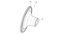
- FIG. 3 is a side view of the buffer portion 70 according to the first embodiment.
- the buffer portion 70 is formed of an elastic body, for example, a silicone rubber, an elastomer, or natural rubber, which is easily deformed and is integrally formed with a material that is easy to adhere to the user's breast when milking.
- silicone rubber when silicone rubber is used, one having a JIS hardness of about 20 to 80 can be used.
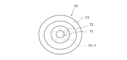
- the buffer portion 70 is shown in cross section in FIG. 4, and is viewed from the front of the enlarged opening in FIG. The state is shown.
- FIG. 5 is different from FIG. 3 in the scale of each part, FIG. 5 schematically shows the shape and structure seen from the front of the buffer part, and does not show a different structure.
- the buffer portion 70 is formed in a trumpet shape along the shape of the opening portion as shown in the drawing on the opening side of the milking enlarged diameter portion 22 so as to enter the inside of the milking opening portion. Has been.
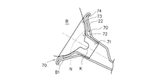
- the buffer portion 70 has a flat trumpet shape that opens in one direction, and has a flat funnel shape as a whole, as will be understood by referring to FIG. Specifically, as shown in FIG. 4, the buffer unit 70 milks the nipple K in a state where the breast (the body B) of the user is brought into contact with the expanded milking part 22 at the center part. A through hole 71 to be exposed in the passage, and a protrusion or concentric protrusion provided near the through hole 71 at a position outside thereof, which is in contact with the user's areola N.
- a contact portion 72 and a concentric protrusion provided at a position on the outer side of the areola contact portion 72 and a breast contact portion 73 that is in close contact with the breast of the user are provided.
- the attachment part 74 which is the outer edge part which this buffer part 70 opened becomes a narrow groove
- the buffer portion 70 can be removed from the milking diameter-expanded portion 70 by turning the attachment portion 74 outward with fingers.
- the buffer part 70 of FIG. 3 is attached to the milking machine 20 described in FIG. 1, when the user abuts his / her breast (main body B) to the milking enlarged diameter part 22 during milking (see FIG. 4), The protruding breast is received in the buffer 70.
- the areola contact portion 72 hits the areola portion N at the tip of the breast body B, and in addition to sucking out the breast milk by the suction force due to the negative pressure, the areola contact portion 72 is By effectively pushing the areola N, breast milk is improved.
- the breast contact portion 73 is brought into close contact with the surface of the breast portion, that is, the region B1 located outside the breast areola other than the areola of the breast, and seals the outer area of the negative pressure. It is possible to effectively prevent leakage of breast milk to the outside.
- both the areola contact portion 72 and the breast contact portion 73 are configured to protrude in a ring shape concentrically with the through-hole 71.
- the present invention is not limited to this, and the areola contact portion 72 may be configured to be projections 72-1 that are in contact with a plurality of portions of the user's areola N near and close to the through hole 71.
- the areola contact portion 72-1 is not protrusive in the form of a ring in the vicinity of the through hole 71, but is formed as a protrusion that protrudes at a plurality of locations, so that the user's areola is used during milking. Since the part N can be reliably pressed at a plurality of locations, it is possible to effectively give a stimulus for improving the milk output.
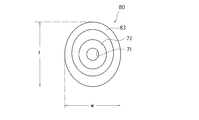
- FIG. 6 is a second embodiment and shows a shape in which the entire buffer portion is formed vertically long. That is, the buffer portion 80 is configured such that the vertical dimension t is larger than the horizontal dimension W as a whole.
- the through-hole 71 is a perfect circle
- the areola contact portion 72 is also a perfect ring shape
- at least the breast contact portion 83 is a vertically long elliptical protrusion.
- vertical refers to the direction along the height of the user in use
- “horizontal” refers to the direction along the width of the body.
- the buffer portion 80 when the buffer portion 80 has a substantially elliptical trumpet shape along the opening of the milking enlarged diameter portion, it is a main body portion of the user's breast.
- the breast body B the tuft portion
- the area of close contact along the vertical direction increases, so that the close contact degree is improved and leakage of breast milk can be effectively prevented.
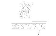
- FIG. 7 is an excerpt from Nezu Hachiman's “Breast Management”.
- T is the apex of the breast nipple.
- S the upper end of the breast (the place where the breast starts) on the front side of the body.
- the four forms (cross-sectional shapes) of the breasts shown in the lower table of FIG. 7 are called I type, IIa type, IIb type, and III type in order from the left side.
- the region b increases as it goes to the left
- the region a increases as it goes to the right.
- type IIb and type III breasts surrounded by a broken line at the right end have large breasts and drooping, and the nipples face downward.
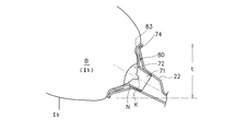
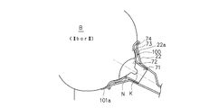
- FIG. 8 In such a breast, the inconvenience shown in FIG. 8 is seen at the time of milking. As shown by the symbol M in FIG. 8, in the breast body B that is greatly swollen, the breast milk leakage caused by the case where the close contact of the breast close contact portion 73 of the buffer portion 70 is insufficient during milking, etc. Often hangs down from the outer edge of 70 and wraps around the lower edge or lower side of the breast to leak.
- FIGS. 9 and 10 it is preferable to use the buffer 80 according to the second embodiment described with reference to FIG.
- FIG. 9 shows a state in which the buffer unit 80 is used for a type IIb breast
- FIG. 10 shows a type III breast. That is, the buffer part 80 is a vertical elliptical buffer part that is long in the direction of the dimension t, and the breast contact part 83 is long in the vertical direction.
- the buffer unit 80 has a larger area of close contact along the vertical direction, so that the degree of contact is improved and leakage of breast milk occurs. Can be effectively prevented.
- the buffer part 100 of FIG. 11 concerns on 3rd Embodiment.
- the buffer portion 100 attached to the milking enlarged diameter portion 22 has an outer edge cover that is extended outwardly from the attachment portion 74 that is the outer edge portion so as to integrally expand in a ring shape along the circumferential direction.
- Part 101 is provided.
- the trumpet-shaped enlarged portion 22a of the milking-expanded portion 22 has a size that can sufficiently receive at least the spindle-shaped portion that is the tip side portion of the breast body B, and the outside thereof.
- the outer edge cover portion 101 of the buffer portion 100 is formed.
- the outer surface of the breast main body can be ring-contacted and sealed, the airtightness is improved and the negative pressure during milking can be used efficiently.
- the breast body B Since the breast body B is covered, breast milk leakage as described in FIG. 8 can be effectively prevented.
- the breast body B Since the breast body B is in surface contact in a ring shape, the burden on the breast body B due to negative pressure during milking can be distributed in a ring shape. Compared with the configuration of FIG. The entire main body B is not drawn into the milking enlarged diameter portion 22, and an unpleasant feeling and pain are not given.
- the cover part 100 does not necessarily have to be provided in a ring shape over the entire periphery of the outer edge part as shown in the figure.
- a tongue-shaped cover portion 101 a may be formed only at the lower edge of the buffer portion 100. That is, as described with reference to FIG. 8, breast milk leakage at the time of milking often leaks around the lower edge or lower side of the breast body B. Therefore, when the outer edge cover portion 101 is provided, at least cover the region.
- the tongue-shaped cover portion 101a extended along the lower outer edge of the buffer portion is effective in preventing breast milk leakage.
- the tongue-shaped cover portion 101a is formed separately from the milking enlarged diameter portion 22 so as to be detachable from the outer edge of the trumpet-shaped milking enlarged diameter portion 22, and the size, shape and preference of the breast of the user You may be able to use it according to.
- the operation means 61 is a handle for operating by hand, it may be an electric drive device that can be connected to the coupling portion (material) 35.
- the mounting portion 41 is formed in the horizontal direction so as to face upward, it may be arranged so as to be inclined obliquely along the air passage 23, and at this time, the air passage 27 on the negative pressure generating member 30 side. Is preferably formed at a position close to one of the mounting portions 41 so that the breast milk flows down.
- all the individual configurations of each embodiment are not necessarily required, and a part of them can be omitted. In this case, a combination of different configurations in combination with other configurations not shown in the drawings is possible. May be implemented, and the configurations of the embodiments may be used in combination.
Landscapes
- Health & Medical Sciences (AREA)
- Heart & Thoracic Surgery (AREA)
- Biomedical Technology (AREA)
- Vascular Medicine (AREA)
- Engineering & Computer Science (AREA)
- Anesthesiology (AREA)
- Hematology (AREA)
- Life Sciences & Earth Sciences (AREA)
- Animal Behavior & Ethology (AREA)
- General Health & Medical Sciences (AREA)
- Public Health (AREA)
- Veterinary Medicine (AREA)
- Pediatric Medicine (AREA)
- External Artificial Organs (AREA)
Abstract
L'objectif de l'invention est de fournir une machine tire-lait pour la prévention de la fuite de lait maternel à partir d'une partie de lactation subissant une expansion de diamètre au cours de la lactation et une perte de pression négative provoquée par la fuite. A cet effet, l'invention concerne une machine tire-lait comprenant : un récipient de réception (11) collectant le lait maternel ; un corps principal de machine tire-lait créant une pression négative pour la lactation ; une partie (22) d'expansion de diamètre de lactation subissant une expansion de diamètre pour entrer en contact avec un sein ; et une partie tampon (70) ayant une forme de couverture presque circulaire le long d'une ouverture de la partie d'expansion de diamètre de lactation, dont au moins une partie entre en contact avec le sein. La partie tampon comprend une partie de contact qui entre en contact avec une aréole ; une partie adhérente qui adhère au sein, etc.
Priority Applications (2)
| Application Number | Priority Date | Filing Date | Title |
|---|---|---|---|
| US14/113,657 US9078962B2 (en) | 2011-04-28 | 2012-04-25 | Breast pump |
| CN201280020432.8A CN103491990A (zh) | 2011-04-28 | 2012-04-25 | 吸乳器 |
Applications Claiming Priority (2)
| Application Number | Priority Date | Filing Date | Title |
|---|---|---|---|
| JP2011-101832 | 2011-04-28 | ||
| JP2011101832A JP5726622B2 (ja) | 2011-04-28 | 2011-04-28 | 搾乳器 |
Publications (1)
| Publication Number | Publication Date |
|---|---|
| WO2012147345A1 true WO2012147345A1 (fr) | 2012-11-01 |
Family
ID=47071875
Family Applications (1)
| Application Number | Title | Priority Date | Filing Date |
|---|---|---|---|
| PCT/JP2012/002844 Ceased WO2012147345A1 (fr) | 2011-04-28 | 2012-04-25 | Machine tire-lait |
Country Status (4)
| Country | Link |
|---|---|
| US (1) | US9078962B2 (fr) |
| JP (1) | JP5726622B2 (fr) |
| CN (1) | CN103491990A (fr) |
| WO (1) | WO2012147345A1 (fr) |
Families Citing this family (9)
| Publication number | Priority date | Publication date | Assignee | Title |
|---|---|---|---|---|
| JP2524841B2 (ja) | 1989-10-20 | 1996-08-14 | 東洋インキ製造株式会社 | ポリオレフィン接着性塗料およびその用途 |
| USD766420S1 (en) * | 2012-09-06 | 2016-09-13 | Mapa Gmbh | Breast pump |
| JP6106585B2 (ja) * | 2013-01-17 | 2017-04-05 | ピジョン株式会社 | 手動搾乳器 |
| USD785160S1 (en) * | 2015-02-20 | 2017-04-25 | Medela Holding Ag | Membrane for a breastshield of a breast pump |
| WO2017083769A1 (fr) * | 2015-11-13 | 2017-05-18 | Naya Health, Inc. | Appareil et procédés pour créer une compression postérieure au niveau du sein pendant l'expression de lait maternel |
| JP6965043B2 (ja) * | 2017-06-30 | 2021-11-10 | ピジョン株式会社 | 手動搾乳器 |
| JP7280667B2 (ja) | 2018-06-05 | 2023-05-24 | ピジョン株式会社 | 搾乳器 |
| EP3725340A1 (fr) * | 2019-04-19 | 2020-10-21 | Koninklijke Philips N.V. | Coussin conçu pour être monté sur un élément de passage d'air d'un dispositif de pompe mammaire |
| EP4631543A1 (fr) | 2024-04-11 | 2025-10-15 | MAM Baby AG | Pompe tire-lait |
Citations (8)
| Publication number | Priority date | Publication date | Assignee | Title |
|---|---|---|---|---|
| FR1067421A (fr) * | 1952-12-04 | 1954-06-15 | Machine à traire fonctionnant sous dépression et pression intermittente conjuguées | |
| US6579258B1 (en) * | 1998-08-24 | 2003-06-17 | Cannon Rubber Limited | Breast pump insert |
| JP2005502397A (ja) * | 2001-06-22 | 2005-01-27 | メデラ ホールディング アクチェンゲゼルシャフト | 多圧力及び膨張可能なチャンバー構造を有する乳房シールド、関連した搾乳器及び方法 |
| JP2008194083A (ja) * | 2007-02-08 | 2008-08-28 | Pigeon Corp | 搾乳器 |
| JP4413231B2 (ja) * | 2005-08-09 | 2010-02-10 | ピジョン株式会社 | 搾乳器 |
| JP4467498B2 (ja) * | 2005-09-29 | 2010-05-26 | ピジョン株式会社 | 搾乳器 |
| JP2010148885A (ja) * | 2001-12-27 | 2010-07-08 | Playtex Products Llc | 搾乳カップ |
| US20110071466A1 (en) * | 2009-09-22 | 2011-03-24 | Medela Holding Ag | Highly efficient breastpump and system for expressing breastmilk |
Family Cites Families (6)
| Publication number | Priority date | Publication date | Assignee | Title |
|---|---|---|---|---|
| US6673037B1 (en) * | 2000-11-27 | 2004-01-06 | Medela Holding Ag | Breastpump shields having modified shape |
| US7396339B2 (en) * | 2004-04-30 | 2008-07-08 | The First Years Inc. | Pumping breast milk |
| JP4774374B2 (ja) * | 2007-01-29 | 2011-09-14 | ピジョン株式会社 | 搾乳装置 |
| US7972297B2 (en) * | 2008-11-07 | 2011-07-05 | Simplisse, Inc. | Breast cup assembly for a breast pump |
| EP2233163A1 (fr) * | 2009-03-26 | 2010-09-29 | Koninklijke Philips Electronics N.V. | Insert pour tire-lait |
| CN201436036U (zh) * | 2009-05-31 | 2010-04-07 | 东莞市嘟宝母婴用品有限公司 | 一种结构改良的手持式吸乳器 |
-
2011
- 2011-04-28 JP JP2011101832A patent/JP5726622B2/ja active Active
-
2012
- 2012-04-25 WO PCT/JP2012/002844 patent/WO2012147345A1/fr not_active Ceased
- 2012-04-25 CN CN201280020432.8A patent/CN103491990A/zh active Pending
- 2012-04-25 US US14/113,657 patent/US9078962B2/en active Active
Patent Citations (8)
| Publication number | Priority date | Publication date | Assignee | Title |
|---|---|---|---|---|
| FR1067421A (fr) * | 1952-12-04 | 1954-06-15 | Machine à traire fonctionnant sous dépression et pression intermittente conjuguées | |
| US6579258B1 (en) * | 1998-08-24 | 2003-06-17 | Cannon Rubber Limited | Breast pump insert |
| JP2005502397A (ja) * | 2001-06-22 | 2005-01-27 | メデラ ホールディング アクチェンゲゼルシャフト | 多圧力及び膨張可能なチャンバー構造を有する乳房シールド、関連した搾乳器及び方法 |
| JP2010148885A (ja) * | 2001-12-27 | 2010-07-08 | Playtex Products Llc | 搾乳カップ |
| JP4413231B2 (ja) * | 2005-08-09 | 2010-02-10 | ピジョン株式会社 | 搾乳器 |
| JP4467498B2 (ja) * | 2005-09-29 | 2010-05-26 | ピジョン株式会社 | 搾乳器 |
| JP2008194083A (ja) * | 2007-02-08 | 2008-08-28 | Pigeon Corp | 搾乳器 |
| US20110071466A1 (en) * | 2009-09-22 | 2011-03-24 | Medela Holding Ag | Highly efficient breastpump and system for expressing breastmilk |
Also Published As
| Publication number | Publication date |
|---|---|
| JP5726622B2 (ja) | 2015-06-03 |
| CN103491990A (zh) | 2014-01-01 |
| JP2012231904A (ja) | 2012-11-29 |
| US9078962B2 (en) | 2015-07-14 |
| US20140094747A1 (en) | 2014-04-03 |
Similar Documents
| Publication | Publication Date | Title |
|---|---|---|
| JP5726622B2 (ja) | 搾乳器 | |
| JP4969262B2 (ja) | 搾乳器 | |
| JP4413231B2 (ja) | 搾乳器 | |
| JP5690806B2 (ja) | 搾乳器用インサート | |
| JP7280667B2 (ja) | 搾乳器 | |
| JP5575893B2 (ja) | 乳房取り付け装置 | |
| JP6106585B2 (ja) | 手動搾乳器 | |
| JP5948406B2 (ja) | 搾乳器 | |
| US8460233B2 (en) | Breastfeeding shield | |
| KR20190116774A (ko) | 모유 착유기 | |
| TW592740B (en) | Manually operated breast pump | |
| JP2019011820A (ja) | 逆流防止弁 | |
| US9216245B2 (en) | Manual breast pump |
Legal Events
| Date | Code | Title | Description |
|---|---|---|---|
| 121 | Ep: the epo has been informed by wipo that ep was designated in this application |
Ref document number: 12777260 Country of ref document: EP Kind code of ref document: A1 |
|
| NENP | Non-entry into the national phase |
Ref country code: DE |
|
| WWE | Wipo information: entry into national phase |
Ref document number: 14113657 Country of ref document: US |
|
| 122 | Ep: pct application non-entry in european phase |
Ref document number: 12777260 Country of ref document: EP Kind code of ref document: A1 |