WO2012147537A1 - 袋状容器内における酸素濃度の非破壊検査装置 - Google Patents
袋状容器内における酸素濃度の非破壊検査装置 Download PDFInfo
- Publication number
- WO2012147537A1 WO2012147537A1 PCT/JP2012/060101 JP2012060101W WO2012147537A1 WO 2012147537 A1 WO2012147537 A1 WO 2012147537A1 JP 2012060101 W JP2012060101 W JP 2012060101W WO 2012147537 A1 WO2012147537 A1 WO 2012147537A1
- Authority
- WO
- WIPO (PCT)
- Prior art keywords
- container
- bag
- oxygen concentration
- laser
- inspection
- Prior art date
- Legal status (The legal status is an assumption and is not a legal conclusion. Google has not performed a legal analysis and makes no representation as to the accuracy of the status listed.)
- Ceased
Links
Images








Classifications
-
- G—PHYSICS
- G01—MEASURING; TESTING
- G01N—INVESTIGATING OR ANALYSING MATERIALS BY DETERMINING THEIR CHEMICAL OR PHYSICAL PROPERTIES
- G01N21/00—Investigating or analysing materials by the use of optical means, i.e. using sub-millimetre waves, infrared, visible or ultraviolet light
- G01N21/17—Systems in which incident light is modified in accordance with the properties of the material investigated
- G01N21/59—Transmissivity
-
- G—PHYSICS
- G01—MEASURING; TESTING
- G01N—INVESTIGATING OR ANALYSING MATERIALS BY DETERMINING THEIR CHEMICAL OR PHYSICAL PROPERTIES
- G01N21/00—Investigating or analysing materials by the use of optical means, i.e. using sub-millimetre waves, infrared, visible or ultraviolet light
- G01N21/01—Arrangements or apparatus for facilitating the optical investigation
-
- G—PHYSICS
- G01—MEASURING; TESTING
- G01N—INVESTIGATING OR ANALYSING MATERIALS BY DETERMINING THEIR CHEMICAL OR PHYSICAL PROPERTIES
- G01N21/00—Investigating or analysing materials by the use of optical means, i.e. using sub-millimetre waves, infrared, visible or ultraviolet light
- G01N21/17—Systems in which incident light is modified in accordance with the properties of the material investigated
- G01N21/25—Colour; Spectral properties, i.e. comparison of effect of material on the light at two or more different wavelengths or wavelength bands
- G01N21/27—Colour; Spectral properties, i.e. comparison of effect of material on the light at two or more different wavelengths or wavelength bands using photo-electric detection ; circuits for computing concentration
- G01N21/274—Calibration, base line adjustment, drift correction
- G01N21/278—Constitution of standards
-
- G—PHYSICS
- G01—MEASURING; TESTING
- G01N—INVESTIGATING OR ANALYSING MATERIALS BY DETERMINING THEIR CHEMICAL OR PHYSICAL PROPERTIES
- G01N21/00—Investigating or analysing materials by the use of optical means, i.e. using sub-millimetre waves, infrared, visible or ultraviolet light
- G01N21/17—Systems in which incident light is modified in accordance with the properties of the material investigated
- G01N21/25—Colour; Spectral properties, i.e. comparison of effect of material on the light at two or more different wavelengths or wavelength bands
- G01N21/31—Investigating relative effect of material at wavelengths characteristic of specific elements or molecules, e.g. atomic absorption spectrometry
- G01N21/35—Investigating relative effect of material at wavelengths characteristic of specific elements or molecules, e.g. atomic absorption spectrometry using infrared light
- G01N21/3504—Investigating relative effect of material at wavelengths characteristic of specific elements or molecules, e.g. atomic absorption spectrometry using infrared light for analysing gases, e.g. multi-gas analysis
-
- G—PHYSICS
- G01—MEASURING; TESTING
- G01N—INVESTIGATING OR ANALYSING MATERIALS BY DETERMINING THEIR CHEMICAL OR PHYSICAL PROPERTIES
- G01N21/00—Investigating or analysing materials by the use of optical means, i.e. using sub-millimetre waves, infrared, visible or ultraviolet light
- G01N21/84—Systems specially adapted for particular applications
- G01N21/88—Investigating the presence of flaws or contamination
- G01N21/90—Investigating the presence of flaws or contamination in a container or its contents
-
- G—PHYSICS
- G01—MEASURING; TESTING
- G01N—INVESTIGATING OR ANALYSING MATERIALS BY DETERMINING THEIR CHEMICAL OR PHYSICAL PROPERTIES
- G01N21/00—Investigating or analysing materials by the use of optical means, i.e. using sub-millimetre waves, infrared, visible or ultraviolet light
- G01N21/01—Arrangements or apparatus for facilitating the optical investigation
- G01N2021/0187—Mechanical sequence of operations
-
- G—PHYSICS
- G01—MEASURING; TESTING
- G01N—INVESTIGATING OR ANALYSING MATERIALS BY DETERMINING THEIR CHEMICAL OR PHYSICAL PROPERTIES
- G01N21/00—Investigating or analysing materials by the use of optical means, i.e. using sub-millimetre waves, infrared, visible or ultraviolet light
- G01N21/01—Arrangements or apparatus for facilitating the optical investigation
- G01N21/03—Cuvette constructions
- G01N2021/0364—Cuvette constructions flexible, compressible
-
- G—PHYSICS
- G01—MEASURING; TESTING
- G01N—INVESTIGATING OR ANALYSING MATERIALS BY DETERMINING THEIR CHEMICAL OR PHYSICAL PROPERTIES
- G01N2201/00—Features of devices classified in G01N21/00
- G01N2201/06—Illumination; Optics
- G01N2201/061—Sources
- G01N2201/06113—Coherent sources; lasers
Definitions
- the present invention relates to a non-destructive inspection apparatus for oxygen concentration in a bag-like container provided in a liquid filling machine and filled with liquid.
- Medical infusion is filled in a bag-like container, for example, an infusion bag, and transported and stored.
- a bag-like container for example, an infusion bag
- This type of inspection method is a destructive inspection in which an injection needle is inserted into a product bag as a sample and air is taken out to measure the oxygen concentration. After the inspection, the sample is discarded. Therefore, the inspection is not a 100% inspection but a specimen inspection, and there is an uncertain aspect regarding the safety and health guarantee.
- it is a method of measuring the oxygen concentration by detecting the degree of absorption by transmitting the laser beam through the upper gas phase in the vial and measuring the amount of transmitted light.
- a material made of a soft material such as an infusion bag is soft, and therefore the thickness changes for each bag to be transported, so that there is a problem that a nondestructive inspection using a laser beam cannot be performed with high accuracy. .
- the present applicant has proposed a nondestructive inspection apparatus capable of accurately inspecting the oxygen concentration in a bag-like container filled with a liquid using a laser beam by nondestructive inspection. .
- This nondestructive inspection apparatus measures the oxygen concentration by irradiating the gas phase part with laser light with the shoulder of the bag held horizontally (for example, Japanese Patent Application Laid-Open No. 2010-38846). Gazette (hereinafter referred to as Patent Document 2)).
- the shoulder portion of the bag is held horizontally to make the thickness of the gas phase portion constant.
- the gravity of the upper portion of the bag is reduced by gravity when the bag is suspended. Since the thickness of the phase part is narrow and the horizontal cross-sectional shape of the gas phase part becomes narrower toward the end, the distance between the laser transmitting part and the laser receiving part sandwiched from both sides of the gas phase part becomes small, There is a problem that it is difficult to measure.
- the present invention has an object to provide a nondestructive inspection device that can be easily measured when the oxygen concentration in a bag-like container filled with a liquid is accurately inspected by nondestructive inspection using a laser beam.
- the first aspect of the present invention is conveyed along a conveyance path having at least a liquid filling area, a sealing area, and an inspection area, which is held by a container holder provided in the conveyance body.
- the liquid filling machine for filling the bag-like container with the liquid the gas phase portion of the bag-like container filled with the liquid is irradiated with the laser beam in the inspection area of the transfer path, and the transmission is performed.
- a laser transmitting unit that transmits a laser beam for measurement and a laser receiving unit that is provided on the other side and that receives the laser beam are provided, and the front end surfaces of the laser transmitting unit and the laser receiving unit have the same length.
- a non-destructive inspection device in which a light inert gas chamber is formed, Provided with a tilting device that is disposed on the left and right of the inspection area of the transport path and is tilted in the vertical plane by pressing the bag-like container that is swingably held in the vertical plane by the container holder from both sides by the container pressing tool. And When measuring the oxygen concentration in the inspection region, the tilting device tilts the bag-like container by a predetermined angle, and a pair of left and right moving members are placed at the upper shoulders of the tilted bag-like container.
- the thickness of the gas phase part is maintained constant and the laser transmitting unit and the laser receiver The air between each front end surface of the part and the surface of the gas phase part of the bag-like container is excluded.
- the container pressing tool in the nondestructive inspection device is provided with a vibration device.
- the conveyance body is stopped when the bag-like container is inspected, and the pair of moving members provided with the laser transmission unit and the laser reception unit are stopped. It is comprised so that it can be made to move with respect to the several bag-shaped container made.
- two calibrations formed of a light-transmitting material and filled with inert gases having different oxygen concentrations in advance outside the inspection region. Place the container for The pair of moving members provided with the laser transmitter and the laser receiver can be moved to a calibration position where the oxygen concentration in the calibration container can be measured.
- the calibration container is formed into a conical shape or a cylindrical shape, the calibration container is rotated about its axis, and the conveyance path is circular. Or it is an oval shape.
- the laser transmitter and the laser receiver With the tip face holding the gas phase part of the container from both sides to a certain thickness, and removing the air between the tip face of the laser transmitter and laser receiver part and the surface of the gas phase part of the bag-like container
- the container is pressed by the container pressing tool, and the container is tilted in the vertical plane, and the gas phase portion of the tilted container shoulder is measured.
- a sufficient volume of oxygen molecules can be moved to the shoulder portion by increasing the volume in the gas phase portion, so that accurate measurement of the oxygen concentration can be easily performed.
- oxygen molecules can be diffused uniformly in the gas phase, and thus stable measurement values with little variation can be obtained even at low oxygen concentrations.
- the cylindrical calibration container is rotated when the inspection tool is calibrated, the calibration can be performed with high accuracy.
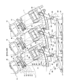
- FIG. 5 is a sectional view taken along line FF in FIG. 3.
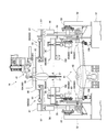
- FIG. 6 is a view taken along arrow GG in FIG. 4. It is principal part sectional drawing of the same nondestructive inspection apparatus. It is a principal part top view of the same nondestructive inspection device.
- FIG. 5 is a view taken along the line HH in FIG.
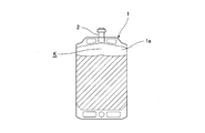
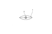
- This nondestructive inspection apparatus is an example of an infusion bag (a bag-like container) made of a soft material (for example, soft plastic such as polyolefin is used) for medical infusion such as infusion (hereinafter referred to as liquid). It is provided in a liquid filling machine that fills a container), and is used to inspect the oxygen concentration in the container filled with the liquid and sealed in the mouth. In addition, whether the oxygen concentration is good or bad is determined by measuring the oxygen concentration in the container using a laser beam and determining based on the measured value (this measurement method is, for example, wavelength tunable semiconductor laser absorption spectroscopy). Called the law).
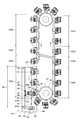
- This liquid filling machine is of a swivel type, and as shown in FIGS. 1 to 4, while holding the container 1 as an infusion bag sequentially and transporting it along the circular transport path 5, 1 is filled with a liquid that is a medical infusion solution, then the mouth 2 is sealed, and after checking the oxygen concentration in the infusion bag filled with the liquid, a protective film is attached to the mouth 2; It is sent to the next process.
- the transport path 5 includes a receiving area 5A for receiving the container 1 (an area is also referred to as a station, hereinafter the same), a gas filling area 5B for filling an inert gas such as nitrogen gas into the container 1 from the mouth 2, and a mouth 2
- the liquid filling area 5C for filling the container 1 with the liquid, the sealing area 5D for capping the mouth part 2 of the container 1 filled with the liquid, and the gas phase part K in the container 1 with the cap are inspected.
- An inspection area 5E, a film attachment area 5F for attaching a protective film to the mouth portion 2, a defective product discharge area 5G for discharging defective products, and a delivery area 5H for delivering the container 1 to the next process are provided.
- a container supply / discharge device capable of supplying and discharging the container is provided at a position facing the receiving area 5A and the delivery area 5H of the container 1.
- the description will be made on the assumption that three containers 1 are moved intermittently three by one, and the respective operations such as filling of the liquid are performed sequentially.
- This liquid filling machine holds containers 1 at predetermined intervals and conveys them along a circular conveyance path 5.
- a gantry 11, a rotation drive device 12 disposed on the gantry 11, and this rotation drive A rotary drive plate 14 connected to a vertical rotary drive shaft 13 on the apparatus 12 side and made rotatable in a horizontal plane, and an annular plate (an inner plate portion and an outer plate portion) connected to the outer periphery of the rotary drive plate 14 15) and a container holder 16 for holding the container 1 by being arranged on the annular plate 15 at a predetermined interval.
- the rotational drive device 12 is configured to intermittently rotate the rotational drive plate 14, that is, the annular plate 15.
- a conveyance body is comprised by the rotational drive device 12, the rotational drive shaft 13, the rotational drive plate 14, the annular plate 15, etc.
- Each container holder 16 includes a mounting plate 21 fixed to the annular plate 15 and a frame-like member 23 provided on the mounting plate 21 via a rotary shaft 22 so as to be rotatable (tiltable) about a horizontal axis.
- a pair of rotary shafts 24 (24A, 24B) rotatably held around the vertical axis in the frame-like member 23, and a pair of gears 25 provided on the rotary shafts 24 and meshed with each other ( 25A, 25B) and a rotary drive device that is connected to the one rotary shaft 24 (24A) via a connecting arm 26 and swings (rotates) the one rotary shaft 24A within a predetermined angle range, for example, for opening and closing.
- a cylinder (air type or electric type is used.
- the same applies to the cylinder) 27 and the mouth 2 of the container 1 can be held and opened from both sides by being attached to the lower end of each rotary shaft 24.
- a pair of holding arms It is constructed from a beam 28 (28A
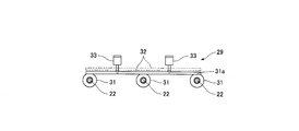
- the posture fixture 29 includes a split-circle-shaped fixing member 31 that is externally fitted to the rotary shaft 22, and a pressing plate that can come into contact with a flat surface portion 31 a that is a split-circle portion of the fixing member 31. 32 and an elevating cylinder 33 that can raise and lower the presser plate 32 to contact and separate from the flat surface portion 31a.
- the posture fixing tool 29 can fix or release the three containers 1 at the same time. For example, the pressing plate 32 is moved up and down by two lifting cylinders 33. The lifting cylinder 33 is attached to the mounting plate 21.
- the pair of holding arms 28 can hold and open the mouth 2 of the container 1 from both sides. Needless to say, for example, a semicircular recess that can engage with the mouth 2 is formed on the front end side of both holding arms 28.
- both shoulder portions 1a of the container 1 held by the container holder 16 are directed from the outside to the inside (to be precise, from the outside of the circular transport path).
- a container presser 41 is provided to prevent the container 1 from shaking by being pressed inside.
- the container presser 41 is connected to a mounting bracket 40 provided at the lower end of the frame-like member 23 via a bearing 42 in the width direction of the container 1 (that is, the tangential direction of the transport path). And a pair of left and right pressing arms 44 fixed at positions corresponding to the shoulders 1a of the container 1 on the rotating shaft 43, A swing cylinder 46 is supported by the mounting bracket 40 and swings the rotary shaft 43 at a predetermined angle via a connecting lever 45.
- the inspection area 5E of the transport path 5 is provided with a nondestructive inspection apparatus 6 according to the present invention.
- the inspection region 5E has a length exceeding the three containers 1 held by the container holders 16 respectively.
- a calibration container (described later) 3 is disposed outside the three containers 1 in order to calibrate the inspection apparatus.
- the inspection region 5E including the portion of the calibration container is referred to as an inspection / calibration region 5E ′.
- the nondestructive inspection apparatus 6 is disposed at a lower position and over a predetermined length in an inspection region 5E having a predetermined length.
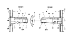
- a support base 51 having a rectangular shape in plan view, and a pair of left and right guide members, for example, guide rails 53, supported in a horizontal direction by a plurality of support members 52 erected on both left and right sides of the support base 51
- a movable plate 55 provided on each of the guide rails 53 via a guide wheel 54, a lift plate 57 provided on the top of the movable plate 55 via a lift cylinder 56, and
- a laser transmitter 59A or a laser beam for inspection which is provided so as to be movable in the approaching / separating direction b with respect to the container 1 by a moving device 58 (58A, 58B) provided on the elevating plate 57 or transmits a laser beam for inspection.
- the gas filling box 61 and the moving device 62 for moving the left and right moving plates 55 simultaneously in the inspection / calibration region 5E ′ are configured.
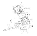
- the gas filling box 61 will be described in detail. As shown in FIG. 15, the front end surface 61a that contacts the container 1 is inclined (or curved) along the surface shape of the container 1 at the time of measurement. .
- each of the moving devices 58 is a rotation disposed on the lifting plate 57 so as to be rotatable in the approaching / separating direction (horizontal direction) b with respect to the container 1 and around its axis.
- the moving member 65 is guided by a guide rod 66 so that it can move only in the approaching / separating direction b, and an electric motor 67 that rotates the rotating screw shaft 63 is provided.
- a pair of rotating screw shafts 63 are arranged on the lifting plate 57.
- the left moving member 65 is attached with a laser transmitting portion 59A, and the other, for example, the right moving member 65 has a laser.
- a receiver 59B is attached.
- the left and right positions of the laser transmitter 59A and the laser receiver 59B may be reversed.
- the laser transmitter 59A and the laser receiver 59B are collectively referred to as an inspection tool 60.
- the moving device 62 is screwed onto the rotating screw shaft 72 (72A, 72B) supported by the intermediate portions of the support members 52 on the left and right via brackets 71 and moved to the rotating screw shaft 72.
- a nut material (a ball screw mechanism is used) 73 connected to the lower end bent portion 55a of the plate 55, driven sprockets 74 attached to the ends of the left and right rotary screw shafts 72, and the driven sprockets.
- a single electric motor 77 that rotates a drive-side sprocket 76 that engages with a conductive belt 75 wound around 74.
- a sprocket 78 for holding the conductive belt and a sprocket 79 for tensioning the conductive belt are arranged.
- the left and right moving plates 55 that is, the laser transmitting unit 59A and the laser receiving unit 59B are simultaneously the stop positions of the three containers 1.
- 1 inspection position (A), 2nd inspection position (B), 3rd inspection position (C), and the 1st calibration position (D) which is a position of two calibration containers 3 provided outside these three containers 1 )
- the second calibration position (E) which is a position of two calibration containers 3 provided outside these three containers 1
- this nondestructive inspection device 6 when measuring with laser light, the container 1 is tilted to collect the gas on the shoulder portion 1a located above, and the thickness of the gas phase portion K is sufficiently secured.
- a tilting device 81 for the container 1 is provided in order to measure the oxygen concentration with high accuracy.
- the tilting device 81 includes three arc-shaped attachments attached to support brackets 82 erected on the left and right sides of the support base 51 in the front-rear direction (conveying direction of the container 1).
- Guide rails 83 (83A, 83B), tilt plates 85 (85A, 85B) guided by the guide rails 83 via a pair of guide wheels 84 that hold the guide rails 83 from above and below, and the tilts
- a lifting plate 87 provided on the plate 85 through a lifting device 86 (86A, 86B) so as to be lifted and lowered, a container pressing tool 88 (88A, 88B) provided on each lifting plate 87, and the tilting plate 85 are provided. It comprises a tilting device 89 (89A, 89B) for moving or tilting along the guide rail 83.
- Each of the elevating devices 86 includes a rotating screw shaft 91 provided on the tilting plate 85 so as to be rotatable in the vertical direction, and a nut member 92 provided on the elevating plate 87 and screwed onto the rotating screw shaft 91.
- Each said container pressing tool 88 is provided in the front-end
- a pressing plate 97 that can press the side surface of the container 1.
- Each tilting device 89 is provided in the support bracket 82 via a support pin 101 so as to be swingable in a vertical plane, and can be engaged with an engaging roller 102 provided on the tilting plate 85 side.
- 103a is composed of a tilting lever 103 formed on the upper end side, and a tilting cylinder 106 connected to the lower end of the tilting lever 103 via a connecting member 104 and a connecting lever 105.
- the three tilting levers 103 are connected to each other by a connecting rod 107 and tilted in synchronization.
- the pressing plate 97 provided on the elevating plate 87 side can be moved up and down to adjust the pressing position of the container 1.
- the rod portion 96a of the left and right container pressing cylinders 96 is protruded and the container 1 is pressed from both sides by the left and right pressing plates 97, the rod portion 106a of the tilting cylinder 106 is protruded.
- the container 1 can be tilted at a predetermined angle.
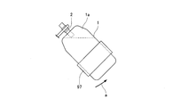
- the container 1 is tilted in the range of 30 to 40 degrees, gas is collected in the shoulder 1a, and the thickness of the gas phase portion K there increases. That is, there are many oxygen molecules in the gas phase portion K, and the oxygen concentration with little error can be easily measured.
- a vibration device 108 is provided on each container pressing tool 88 side, that is, on the lower surface of each lifting plate 87, and the container 1 pressed (held) by the pressing plate 97 is vibrated to give vibration inside the container 1.
- the measurement accuracy is improved by moving the gas entering the liquid phase part, that is, oxygen, upward.
- vibration device 108 for example, an air drive type or an electric drive type is used.
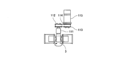
- the calibration container 3 is disposed at both ends of the support frame 51, that is, at the front and rear positions, and is formed in a cylindrical shape (box shape) using a translucent material (for example, an acrylic plate is used). And is configured to be rotatable about a horizontal axis.
- the calibration container 3 is supported on the support base 51 side so as to be rotatable about a horizontal axis via a support member 111 and the like, and a pair of pulleys is provided on the support shaft portion.
- the motors 115 and 113 and the conduction belt 114 are linked to the motor 115 and are rotated at 5 to 10 rpm, for example, during calibration.
- the calibration container 3 ′ may have a conical shape so as to match the surface shape of the shoulder 1a of the container 1, and the electric motor can be directly used without using a pulley and a conduction belt.
- the calibration container 3 may be rotated.
- the calibration container 3 ′ is installed in such a direction that the change in the conical shape coincides with the change in the thickness of the shoulder 1 a in the container 1.
- the calibration container 3 is filled with nitrogen gas as an inert gas having a predetermined oxygen concentration.
- nitrogen gas as an inert gas having a predetermined oxygen concentration.
- the oxygen concentration of one calibration container 3A is set to 0%
- the oxygen concentration of the other calibration container 3B is set to 20%.
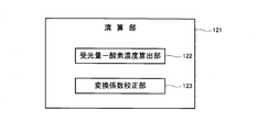
- the nondestructive inspection apparatus 6 includes a calculation unit 121.
- the calculation unit 121 includes a detection value from the laser reception unit 59B, that is, a transmitted light amount of laser light.
- a received light amount—oxygen concentration calculation unit 122 for inputting an amount of received light to obtain an oxygen concentration and a detection value of the oxygen concentration in the two calibration containers 3 are input, and a conversion set in the received light amount—oxygen concentration calculation unit 122
- a conversion coefficient calibration unit 123 for calibrating the coefficient (also referred to as sensitivity coefficient) R is provided.
- the received light amount-oxygen concentration calculation unit 123 is provided with a graph representing the relationship between the received light amount and the oxygen concentration, that is, a conversion coefficient R.
- the conversion coefficient calibration unit 123 obtains the current graph, that is, the conversion coefficient R ′ based on the amount of light received when the two calibration containers 3 are inspected.
- this graph is obtained by measuring the amount of light received at 0% density and the amount of light received at 20% density.
- the value of the oxygen concentration in the two calibration containers 3 can be appropriately changed according to the measurement range of the measurement target.
- the obtained graph that is, the new conversion coefficient R ′ is input to the received light amount-oxygen concentration calculation unit 122, and this new conversion coefficient R ′ is used thereafter.
- the current conversion coefficient R is used.
- the containers 1 are moved from the feeder to the receiving area 5A of the transport path 5 and are sequentially held three by three by the container holder 16 provided on the annular plate 15.
- the posture fixing tool 29 is first released so that the container 1 can tilt.
- the lower part of the container 1 is pressed from both sides by the pressing plates 97 of the container pressing tools 88A and 88B in the tilting device 81 disposed below, and the gas in the container 1 is moved upward, and then FIG. As shown, the container 1 is tilted in the predetermined direction a by the tilting devices 89A and 89B, and the one shoulder 1a is positioned upward. In this state, the quality inspection of the three containers 1 is performed in order.
- the inspection tool 60 stopped at the first calibration position (D) is moved to the first inspection position (A).
- the moving member 65 is protruded toward the container 1 by the moving device 58. That is, as shown in FIG. 15, the left and right gas filling boxes 61 are brought close to each other so that the gas phase portion K of the shoulder portion 1 a of the container 1 is sandwiched by a certain distance from both sides. Therefore, the air layer existing between the gas filling box 61 and the gas phase portion K of the container 1 is excluded.
- laser light is transmitted from the laser transmitter 59A, passes through the container 1, and is received by the laser receiver 59B.
- the received light amount which is the transmitted light amount of the laser light detected by the laser receiving unit 59B, is input to the calculation unit 121, where the oxygen concentration is obtained based on the received light amount (also the dimming rate) of the laser light.
- the quality of the oxygen concentration that is, the quality is judged.
- a determination unit for determining whether the oxygen concentration is good or bad by comparing with a set value is provided.
- the laser transmitter 59A and the laser receiver 59B that is, the inspection tool 60 are moved to the second inspection position (B) by the moving device 62, and similarly the second The container 1 is inspected. Thereafter, the inspection tool 60 is further moved to the third inspection position (C) by the moving device 62 and the third container 1 is inspected.
- the oxygen concentration in the container 1 is defective, that is, when the oxygen concentration exceeds an allowable value, the quality is determined to be poor, and the protective film is not attached, but is directly transferred to the defective product discharge area 5G. Discharged outside.
- the container 1 After the inspection of the three containers 1 is completed, the container 1 is returned from the tilting posture to the vertical posture by the tilting device 81, and then the three containers 1 are fixed by the posture fixing tool 29, and the annular drive plate 12 is rotated by the rotary drive device 12. 15 is rotated, and the next three containers 1 are transported to the inspection area E for inspection.
- the inspection tool 60 sequentially moves in the direction opposite to the previous inspection, and the three containers 1 are inspected.
- the same inspection that is, the calibration operation is performed on the calibration container 3 at each position.
- the calibration container 3 is rotated about the horizontal axis.
- This calibration operation is performed when set in advance, for example, every few hours, or at the start of work on the day.
- the inspection result in this calibration operation is input to the conversion coefficient calibration unit 123, and a graph showing the relationship between the amount of received laser light and the oxygen concentration, that is, the conversion coefficient R is calibrated.
- the tips of these laser transmitter and laser receiver By pressing the gas phase part of the container from both sides to obtain a certain thickness, the laser is removed from the air between the tip surface of the laser transmitting part and the laser receiving part and the surface of the gas phase part of the bag-like container.
- the lower part of the container is pressed (held) by the container pressing tool, and the container is tilted in the vertical plane, and the gas phase portion of the tilted shoulder of the container Since the volume in the gas phase portion is increased, a sufficient amount of oxygen molecules can be moved to the shoulder portion, so that it is possible to easily measure the oxygen concentration with high accuracy.
- oxygen molecules can be diffused uniformly in the gas phase, and thus stable measurement values with little variation can be obtained even at low oxygen concentrations.
- the cylindrical calibration container is rotated when the inspection tool is calibrated, the calibration can be performed with high accuracy.
- inspection tool 60 was moved in order with respect to the three containers 1, the test
- route 5 of the container 1 was circular, ie, the swivel type was demonstrated, as shown in FIG. 16, for example, the straight line whose conveyance path
- the oxygen concentration in the container is measured by the inspection tool in a state where one container is tilted, and thus the tilting device and the inspection tool can be moved together at each inspection position. Has been.
- the nondestructive inspection device 141 includes a support base 142 provided on a side portion of the casing 132 of the rotary drive device 131 in a linear liquid filling machine, and a support column provided upright on the outer edge of the support base 142.
- a guide rail 144 which is a guide member attached to the member 143 in the horizontal direction, and a front view (longitudinal section) guided by the guide rail 144 by the upper and lower guide wheels 145 has a groove shape (the bottom plate 146a and the bottom plate 146a
- a movable body 146 comprising a side plate 146b erected from the left and right, a moving device 147 for moving the movable body 146 in a predetermined direction (front-rear direction, in other words, a container transport direction at the inspection position), and the movement
- a container pressing tool 149 (which is provided on the body 146 so as to be tiltable in a predetermined direction a via a tilting device 148 and can press (hold) the lower portion of the container 1 49A, 149B), the laser transmitter 150A and the laser receiver 150B, which are the inspection tools 151 of the container 1 provided on the movable body 146 and above the container pressing tool 149, and these transmitters 150A and receivers. It is
- the moving device 147 is provided on a pair of front and rear support brackets 153 projecting from the lower part of the column member 143 toward the inspection path, and is provided on the front and rear support brackets 153 so as to be rotatable in the front-rear direction and around its axis.
- an electric motor 156 to be operated. Therefore, by rotating the rotating screw shaft 155 by the electric motor 156, the moving body 146, that is, the inspection tool 151 and the container pressing tool 149, together with each inspection position (A, B, C) and calibration position (D , E).
- the container pressing tool 149 has the same configuration as that of the above-described embodiment, and a description thereof will be omitted.
- the electric motor 67 that rotates the rotary screw shaft 63 is disposed above the lifting plate 57, but in the linear inspection tool 151, An electric motor 162 that rotates the rotating screw shaft 161 is provided below the elevating plate body 163 on which the inspection tool 151 is disposed.
- the three containers 1 are tilted simultaneously.
- the linear tilting device 148 in the linear tilting device 148, one container 1 is tilted.
- the tilting device 148 has the same basic structure as that of the above-described embodiment, but specifically differs in that the guide roller 172 provided on the tilting plate 171 is not a guide rail but a moving body 146.
- the tilting cylinder 174 for tilting the tilting plate 171 is naturally supported on the moving body 146 side, for example, on the side plate 146b. Yes.
- the calibration container 3 is provided at each calibration position (D, E) so that it can rotate around the horizontal axis as in the above-described embodiment.
- the posture fixing tool (29) of the container 1 when measuring the oxygen concentration in the container 1, when the container 1 is moved to three inspection positions (A, B, C), the posture fixing tool (29) of the container 1 is used at each position. The posture fixing of the container 1 is released.
- the container 1 is tilted in the predetermined direction a by the tilting device 148 and gas Is moved to the shoulder 1a.
- the gas filling box 152 provided in the inspection tool 151 that is, the laser transmitter 150 ⁇ / b> A and the laser receiver 150 ⁇ / b> B is brought into contact with the shoulder 1 a of the container 1 to measure the oxygen concentration in the gas phase part K of the container 1. Done.
- vibration is applied to the container 1 by the vibration device (108) during measurement.
- the number (number) which shows the member in the said parenthesis is the same member as what was demonstrated in embodiment mentioned above, the same number is attached
- the left and right gas filling boxes are brought close to each other so that the gas phase portion of the shoulder portion of the bag-like container is sandwiched at a predetermined distance from both sides.
- the lower portion of the bag-like container is sandwiched between the left and right pressing plates so that the shoulder portion is inflated and the surface thereof is brought into contact with the left and right gas filling boxes. . That is, the amount of movement of the pressing plate is controlled so that the surface of the bag-like container contacts the surfaces of the left and right gas-filled boxes that are close to each other.
- the interval is always kept constant, thus improving the measurement accuracy.
Landscapes
- Physics & Mathematics (AREA)
- General Physics & Mathematics (AREA)
- Pathology (AREA)
- Life Sciences & Earth Sciences (AREA)
- Chemical & Material Sciences (AREA)
- Analytical Chemistry (AREA)
- Biochemistry (AREA)
- Health & Medical Sciences (AREA)
- Immunology (AREA)
- General Health & Medical Sciences (AREA)
- Spectroscopy & Molecular Physics (AREA)
- Engineering & Computer Science (AREA)
- Mathematical Physics (AREA)
- Theoretical Computer Science (AREA)
- Investigating Or Analysing Materials By Optical Means (AREA)
- Examining Or Testing Airtightness (AREA)
Priority Applications (3)
| Application Number | Priority Date | Filing Date | Title |
|---|---|---|---|
| EP12776432.2A EP2703802B1 (de) | 2011-04-28 | 2012-04-13 | Flüssigkeitsfüllvorrichtung mit einer vorrichtung zur zerstörungsfreien prüfung der sauerstoffkonzentration in einem beutelförmigen behälter |
| US14/112,274 US8848193B2 (en) | 2011-04-28 | 2012-04-13 | Non-destructive inspection device for oxygen concentration in bag-shaped container |
| CN201280017714.2A CN103460023B (zh) | 2011-04-28 | 2012-04-13 | 袋状容器内的氧浓度的非破坏检查装置 |
Applications Claiming Priority (2)
| Application Number | Priority Date | Filing Date | Title |
|---|---|---|---|
| JP2011100289A JP5686662B2 (ja) | 2011-04-28 | 2011-04-28 | 袋状容器内における酸素濃度の非破壊検査装置 |
| JP2011-100289 | 2011-04-28 |
Publications (1)
| Publication Number | Publication Date |
|---|---|
| WO2012147537A1 true WO2012147537A1 (ja) | 2012-11-01 |
Family
ID=47072059
Family Applications (1)
| Application Number | Title | Priority Date | Filing Date |
|---|---|---|---|
| PCT/JP2012/060101 Ceased WO2012147537A1 (ja) | 2011-04-28 | 2012-04-13 | 袋状容器内における酸素濃度の非破壊検査装置 |
Country Status (5)
| Country | Link |
|---|---|
| US (1) | US8848193B2 (de) |
| EP (1) | EP2703802B1 (de) |
| JP (1) | JP5686662B2 (de) |
| CN (1) | CN103460023B (de) |
| WO (1) | WO2012147537A1 (de) |
Cited By (1)
| Publication number | Priority date | Publication date | Assignee | Title |
|---|---|---|---|---|
| CN114324200A (zh) * | 2022-01-06 | 2022-04-12 | 安徽庆宇光电科技有限公司 | 一种模拟校准装置及机动车尾气遥感监测设备 |
Families Citing this family (12)
| Publication number | Priority date | Publication date | Assignee | Title |
|---|---|---|---|---|
| JP5791459B2 (ja) * | 2011-10-17 | 2015-10-07 | 日立造船株式会社 | 電子線殺菌設備の遮蔽構造 |
| JP6588426B2 (ja) * | 2013-05-27 | 2019-10-09 | ガスポロックス エービー | 容器中の気体の濃度を判定するためのシステムおよび方法 |
| CN105417102B (zh) * | 2016-01-08 | 2017-08-01 | 湖南科伦制药有限公司 | 一种粉‑液双腔室输液袋灯检夹具 |
| CN109863385B (zh) * | 2016-11-04 | 2022-10-04 | 威尔科股份公司 | 用于测量气体的浓度的方法和设备 |
| EP3803352B1 (de) | 2018-06-07 | 2023-07-12 | Wilco AG | Vorrichtung zur detektion eines gases in einem kopfraum eines behälters |
| IT201900006691A1 (it) * | 2019-05-09 | 2020-11-09 | G F S P A | Metodo e apparato di ispezione di una sacca per fluidi |
| EP4150320B1 (de) * | 2020-05-14 | 2025-07-23 | GasPorOx AB | System und verfahren zur bestimmung einer konzentration eines gases in einem behälter |
| CN112756266B (zh) * | 2020-11-23 | 2022-10-21 | 四川极智朗润科技有限公司 | 一种液袋灯检系统 |
| JP7607919B2 (ja) * | 2021-05-10 | 2025-01-06 | ゼネラルパッカー株式会社 | ピロー包装袋のガス濃度測定方法 |
| JP2022174863A (ja) * | 2021-05-12 | 2022-11-25 | ゼネラルパッカー株式会社 | 輸液バッグの酸素濃度測定方法および輸液バッグ |
| CN115078311B (zh) * | 2022-06-20 | 2024-09-17 | 山东省医疗器械和药品包装检验研究院 | 一种避光输液袋的检测系统 |
| DE102023110811A1 (de) * | 2023-04-26 | 2024-10-31 | Weber Food Technology Gmbh | Vorrichtung und Verfahren zum Messen einer Eigenschaft eines in einer Lebensmittelverpackung befindlichen Gases |
Citations (5)
| Publication number | Priority date | Publication date | Assignee | Title |
|---|---|---|---|---|
| JPS62206830A (ja) * | 1986-03-07 | 1987-09-11 | Toshiba Corp | レジスト液塗布方法 |
| JP2005189196A (ja) * | 2003-12-26 | 2005-07-14 | Kokando:Kk | 液中異物検査装置 |
| JP2007508567A (ja) | 2003-10-15 | 2007-04-05 | ライトハウス インスツルメンツ, エルエルシー | 自動ヘッドスペース分析のためのシステム及び方法 |
| JP2009014589A (ja) * | 2007-07-06 | 2009-01-22 | General Packer Co Ltd | 包装機におけるガス濃度測定方法 |
| JP2010038846A (ja) | 2008-08-08 | 2010-02-18 | Hitachi Zosen Corp | 袋状容器内における酸素濃度の非破壊検査装置 |
Family Cites Families (5)
| Publication number | Priority date | Publication date | Assignee | Title |
|---|---|---|---|---|
| JPS58117442A (ja) * | 1982-01-05 | 1983-07-13 | Hoshitaka Nakamura | ソフトバツク内容液中の異物検査方法及び装置 |
| US5510621A (en) * | 1994-10-03 | 1996-04-23 | Optical Solutions, Inc. | Apparatus and method for measuring components in a bag |
| JPWO2005031328A1 (ja) * | 2003-09-30 | 2007-11-15 | エーザイ・アール・アンド・ディー・マネジメント株式会社 | 検査システム |
| CN101319954B (zh) * | 2008-07-17 | 2010-08-18 | 长沙楚天科技有限公司 | 软袋大输液生产线用膜袋质量检测装置 |
| JP2012189386A (ja) * | 2011-03-09 | 2012-10-04 | Panasonic Corp | 成分分析装置 |
-
2011
- 2011-04-28 JP JP2011100289A patent/JP5686662B2/ja active Active
-
2012
- 2012-04-13 US US14/112,274 patent/US8848193B2/en active Active
- 2012-04-13 EP EP12776432.2A patent/EP2703802B1/de active Active
- 2012-04-13 WO PCT/JP2012/060101 patent/WO2012147537A1/ja not_active Ceased
- 2012-04-13 CN CN201280017714.2A patent/CN103460023B/zh not_active Expired - Fee Related
Patent Citations (5)
| Publication number | Priority date | Publication date | Assignee | Title |
|---|---|---|---|---|
| JPS62206830A (ja) * | 1986-03-07 | 1987-09-11 | Toshiba Corp | レジスト液塗布方法 |
| JP2007508567A (ja) | 2003-10-15 | 2007-04-05 | ライトハウス インスツルメンツ, エルエルシー | 自動ヘッドスペース分析のためのシステム及び方法 |
| JP2005189196A (ja) * | 2003-12-26 | 2005-07-14 | Kokando:Kk | 液中異物検査装置 |
| JP2009014589A (ja) * | 2007-07-06 | 2009-01-22 | General Packer Co Ltd | 包装機におけるガス濃度測定方法 |
| JP2010038846A (ja) | 2008-08-08 | 2010-02-18 | Hitachi Zosen Corp | 袋状容器内における酸素濃度の非破壊検査装置 |
Cited By (2)
| Publication number | Priority date | Publication date | Assignee | Title |
|---|---|---|---|---|
| CN114324200A (zh) * | 2022-01-06 | 2022-04-12 | 安徽庆宇光电科技有限公司 | 一种模拟校准装置及机动车尾气遥感监测设备 |
| CN114324200B (zh) * | 2022-01-06 | 2024-04-02 | 安徽庆宇光电科技有限公司 | 一种模拟校准装置及机动车尾气遥感监测设备 |
Also Published As
| Publication number | Publication date |
|---|---|
| US8848193B2 (en) | 2014-09-30 |
| EP2703802B1 (de) | 2018-07-25 |
| EP2703802A1 (de) | 2014-03-05 |
| US20140029007A1 (en) | 2014-01-30 |
| JP2012233701A (ja) | 2012-11-29 |
| CN103460023A (zh) | 2013-12-18 |
| EP2703802A4 (de) | 2015-04-01 |
| CN103460023B (zh) | 2015-08-19 |
| JP5686662B2 (ja) | 2015-03-18 |
Similar Documents
| Publication | Publication Date | Title |
|---|---|---|
| JP5686662B2 (ja) | 袋状容器内における酸素濃度の非破壊検査装置 | |
| JP5137740B2 (ja) | 袋状容器内における酸素濃度の非破壊検査装置 | |
| EP1687593B1 (de) | System und verfahren zur automatischen kopfraum-analyse | |
| JP5124719B2 (ja) | 包装機におけるガス濃度測定方法 | |
| CN105556315B (zh) | 测试片取用机构、测试片移动装置、液体试样分析装置及测试片取用方法 | |
| KR101582797B1 (ko) | 스파우트 캡 조립 장치 및 조립 방법 | |
| EP2372344A1 (de) | Verfahren zur Analyse einer Gaskomponente in einem hermetisch verschlossenen Behälter | |
| KR20200067236A (ko) | 레이저 분광 검사방법 및 레이저 분광 검사장치 | |
| ITMI20120108A1 (it) | Gruppo di misura in linea della quantita' di anidride carbonica disciolta in un liquido contenuto in un contenitore chiuso e linea di riempimento automatico di contenitori comprendente lo stesso | |
| US20170268996A1 (en) | Method and device for measuring the gas content of materials packaged in plastic films, glass or other light-permeable materials and sensitive to a gas to be measured | |
| JP2021096133A (ja) | 包装袋用ガス濃度測定装置 | |
| US20240077394A1 (en) | Apparatus, plant and method for inspecting flexible packages | |
| JP7350312B2 (ja) | 包装容器内のガス濃度測定方法 | |
| JP5555923B2 (ja) | 包装機におけるガス濃度測定方法 | |
| JP2000018923A (ja) | ローラ類の振れ及び外径検査装置 | |
| CN120133166B (zh) | 一种药用玻璃瓶质量检测装置 | |
| JP7779477B2 (ja) | 包装容器内の残存酸素濃度測定方法 | |
| WO2022244646A1 (ja) | 包装袋のガス濃度測定装置およびそれを備えた包装機並びに包装袋のガス濃度測定方法 | |
| JP2012108157A (ja) | 包装機におけるガス濃度測定方法 | |
| CN118417178A (zh) | 基于药品安全的药品密封性自动化检测装置及方法 | |
| JP2021128068A (ja) | 容器内ガス性状の測定装置 |
Legal Events
| Date | Code | Title | Description |
|---|---|---|---|
| 121 | Ep: the epo has been informed by wipo that ep was designated in this application |
Ref document number: 12776432 Country of ref document: EP Kind code of ref document: A1 |
|
| WWE | Wipo information: entry into national phase |
Ref document number: 2012776432 Country of ref document: EP |
|
| WWE | Wipo information: entry into national phase |
Ref document number: 14112274 Country of ref document: US |
|
| NENP | Non-entry into the national phase |
Ref country code: DE |