WO2012147562A1 - 偏光板用保護フィルムの製造方法、偏光板用保護フィルム、偏光板及び液晶表示装置 - Google Patents
偏光板用保護フィルムの製造方法、偏光板用保護フィルム、偏光板及び液晶表示装置 Download PDFInfo
- Publication number
- WO2012147562A1 WO2012147562A1 PCT/JP2012/060336 JP2012060336W WO2012147562A1 WO 2012147562 A1 WO2012147562 A1 WO 2012147562A1 JP 2012060336 W JP2012060336 W JP 2012060336W WO 2012147562 A1 WO2012147562 A1 WO 2012147562A1
- Authority
- WO
- WIPO (PCT)
- Prior art keywords
- protective film
- resin
- polarizing plate
- film
- stretching
- Prior art date
- Legal status (The legal status is an assumption and is not a legal conclusion. Google has not performed a legal analysis and makes no representation as to the accuracy of the status listed.)
- Ceased
Links
Images





Classifications
-
- C—CHEMISTRY; METALLURGY
- C08—ORGANIC MACROMOLECULAR COMPOUNDS; THEIR PREPARATION OR CHEMICAL WORKING-UP; COMPOSITIONS BASED THEREON
- C08J—WORKING-UP; GENERAL PROCESSES OF COMPOUNDING; AFTER-TREATMENT NOT COVERED BY SUBCLASSES C08B, C08C, C08F, C08G or C08H
- C08J5/00—Manufacture of articles or shaped materials containing macromolecular substances
- C08J5/18—Manufacture of films or sheets
-
- G—PHYSICS
- G02—OPTICS
- G02B—OPTICAL ELEMENTS, SYSTEMS OR APPARATUS
- G02B1/00—Optical elements characterised by the material of which they are made; Optical coatings for optical elements
- G02B1/10—Optical coatings produced by application to, or surface treatment of, optical elements
- G02B1/11—Anti-reflection coatings
- G02B1/111—Anti-reflection coatings using layers comprising organic materials
Definitions
- the present invention relates to a method for producing a protective film for a polarizing plate. Moreover, it is related with the protective film for polarizing plates manufactured by the said manufacturing method, the polarizing plate provided with it, and a liquid crystal display device.
- the liquid crystal display device (hereinafter also referred to as “LCD”) includes a backlight unit, a liquid crystal cell, and a polarizing plate.
- the polarizing plate usually comprises a protective film for a polarizing plate and a polarizer (also referred to as “polarizing film”).
- polarizer a polyvinyl alcohol film dyed with iodine and stretched is often used, and both surfaces thereof are covered with a protective film for a polarizing plate.
- a cellulose triacetate (TAC) film having excellent moisture permeability and excellent adhesion to a polarizer is often used.
- a light source such as a cold cathode tube (CCFL) or LED is provided on the back side (backlight side) of the liquid crystal cell or on the edge portion (side light side) of the light guide plate. Is always placed. Since these light sources are generally line light sources or point light sources, a light diffusion sheet or a light diffusion film (also referred to as a “diffusion sheet” or “diffusion film”) is used in order to form a uniform surface light source. ing.
- the light diffusion sheet is an interference fringe such as moire generated by interference between a prism sheet often used as a member for imparting directivity to light and incident light, or by interference between pixels in a liquid crystal cell and incident light. Can be suppressed.
- Patent Document 1 proposes a light diffusing polarizing plate having a light diffusing layer having predetermined characteristics, which contains porous amorphous particles and spherical particles in a dispersed manner, and discloses that a light diffusing sheet can be omitted by this. ing. According to this method, it is possible to eliminate moiré fringes, but when forming a polarizing plate, there is a problem that fine particles fall off and cause process contamination, and the front luminance decreases when a display device is used. There was a problem.
- Patent Documents 2 and 3 it is proposed to use a light diffusion film containing translucent fine particles and crosslinkable fine particles as a protective film for a polarizing plate.
- a light diffusion film containing translucent fine particles and crosslinkable fine particles as a protective film for a polarizing plate.
- problems such as the dropout of fine particles when forming a polarizing plate as described above, and the problem that it cannot be produced at low cost.
- Patent Documents 4 and 5 a dope comprising a plurality of resins is cast on a support, and a phase-separated scattering film having a sea-island structure or a mixed solution of a plurality of resins is applied on the support film.
- a light scattering film is disclosed. According to this method, a film having light diffusibility can be produced, and since the fine particles are not used, the problem of fine particle dropping off can be solved.
- the film is used as a protective film for a polarizing plate while maintaining light diffusibility, the transmittance is lowered and the luminance when the display device is formed is lowered. It was also found that there was a problem that the film became brittle due to peeling at the interface between the sea part and the island part.
- An object of the present invention is to provide a method for producing a protective film for a polarizing plate, which can produce a protective film for a polarizing plate having moiré-resolving ability by an easy process without causing process contamination due to dropping off of fine particles. Moreover, it is providing the said protective film for polarizing plates in which the problem of brittleness was overcome. Furthermore, it is providing the polarizing plate and liquid crystal display device which were equipped with the protective film for polarizing plates manufactured with the said manufacturing method.
- the inventors of the present invention have intensively studied to solve the above-mentioned problems, and have found out means for overcoming the above-mentioned problems and have reached the present invention.
- a method for producing a protective film for a polarizing plate characterized in that an absolute value of a difference in refractive index is 0.08 or less and the following steps (a) to (d) are included.
- Stretching speed (% / min) ⁇ (width dimension after stretching / width dimension before stretching) -1 ⁇ ⁇ 100 (%) / time required for stretching (min) 3.
- the protective film for polarizing plates manufactured by the manufacturing method of the protective film for polarizing plates as described in any one of said 1st term
- the total haze value of one protective film for polarizing plate is in the range of 20 to 80%, and the internal haze value obtained by (total haze value) ⁇ (surface haze value) is 0.15 to 30%.
- a polarizing plate comprising a polarizing plate protective film produced by the method for producing a polarizing plate protective film according to any one of Items 1 to 3.
- a liquid crystal display device comprising a polarizing plate protective film manufactured by the method for manufacturing a polarizing plate protective film according to any one of items 1 to 3.
- the protective film for polarizing plate having sufficient moire eliminating ability without lowering the front luminance is removed.
- the manufacturing method of the protective film for polarizing plates which can be produced with an easy process without the process contamination by can be provided.
- the said protective film for polarizing plates with which the brittle problem was overcome can be provided.
- the polarizing plate provided with the protective film for polarizing plates manufactured with the said manufacturing method and the liquid crystal display device can be provided.
- the difference between the glass transition temperature Tg (A) of the resin A as the main component constituting the island and the glass transition temperature Tg (B) of the resin B as the main component constituting the sea is set to a specific temperature or more.
- the temperature T in the stretching step to a temperature between Tg (B) and Tg (A)
- the projecting state of the island structure can be controlled. That is, the arithmetic average roughness Ra and haze of the surface of the protective film for polarizing plate can be controlled within an appropriate range, and sufficient moire eliminating ability can be imparted without causing a decrease in transmittance.
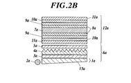
- the figure which showed typically an example of the dope preparation process, casting process, and drying process of a solution casting film forming method The figure which showed the example of the structure of the conventional backlight type liquid crystal display device typically. The figure which showed the example of the structure of the conventional sidelight type liquid crystal display device typically The figure which showed typically the example of a structure of the backlight type liquid crystal display device of this invention The figure which showed typically the example of a structure of the sidelight type liquid crystal display device of this invention
- the method for producing a protective film for a polarizing plate of the present invention is a method for producing a protective film for a polarizing plate having a sea-island structure comprising a continuous phase corresponding to the sea and a dispersed phase corresponding to an island, and constitutes the island.
- the difference (Tg (A) ⁇ Tg (B)) between the glass transition temperature Tg (A) of the resin A as the main component and the glass transition temperature Tg (B) of the resin B as the main component constituting the sea is 10
- the temperature difference is higher than 0 ° C., the difference in refractive index between the resin A and the resin B is 0.08 or less, and the steps (a) to (d) are included.
- This feature is a technical feature common to the inventions according to claims 1 to 7.
- the stretching speed in the stretching step determined by the formula (I) is in the range of 20 to 300% / min. Furthermore, it is preferable that the weight average molecular weight (Mw) of at least one of the resin A and the resin B is 180,000 or more.
- the arithmetic average roughness Ra of at least one surface of the protective film for polarizing plate is in the range of 0.08 to 2.0 ⁇ m. It is preferable to be within. Further, the total haze value of one protective film for polarizing plate is in the range of 20 to 80%, and the internal haze value obtained by (total haze value) ⁇ (surface haze value) is 0.15 to 30. % Is preferably in the range of%.
- the protective film for polarizing plate produced by the method for producing a protective film for polarizing plate of the present invention can be suitably used for a polarizing plate and a liquid crystal display device.
- the “sea-island structure” means that when a plurality of (for example, two) resin components that are incompatible with each other are mixed, the higher-order structure of the mixture is a phase in which one of the resin components is continuous.
- the other is a structure in which islands or particles are dispersed. That is, it means a structure formed by one resin being a continuous phase (matrix) corresponding to the sea and the other being a dispersed phase corresponding to the island.
- ⁇ is used to mean that the numerical values described before and after it are included as a lower limit value and an upper limit value.
- the method for producing a protective film for a polarizing plate of the present invention is a method for producing a protective film for a polarizing plate having a sea-island structure comprising a continuous phase corresponding to the sea and a dispersed phase corresponding to an island, and constitutes the island.
- the difference (Tg (A) ⁇ Tg (B)) between the glass transition temperature Tg (A) of the resin A as the main component and the glass transition temperature Tg (B) of the resin B as the main component constituting the sea is 10
- the difference in refractive index between the resin A and the resin B is 0.08 or less, and the following steps (a) to (d) are included.
- the glass transition temperature Tg (A) of the resin A as the main component constituting the island is higher than the glass transition temperature of the resin B as the main component composing the sea, and the difference between the two ( Tg (A) ⁇ Tg (B)) is more than 10 ° C.
- the present invention is characterized in that the manufacturing method includes the steps (a) to (d).
- a protective film for a polarizing plate imparted with a light diffusing ability which overcomes the brittleness problem that has been a problem with conventional scattering films made of resin blends.
- a protective film for a liquid crystal display device, particularly a backlight-side polarizing plate it is possible to provide an image display device with excellent image quality in which moire fringes are eliminated without lowering the front luminance.
- Tg (B)) is more than 10 ° C.
- the film is stretched so that the temperature T in the stretching process satisfies Tg (B) ⁇ T ⁇ Tg (A).
- the protruding state of the island structure can be controlled, and sufficient moire can be achieved without causing a decrease in transmittance.
- a resolution ability can be imparted.
- the difference in glass transition temperature between resin A and resin B is 10 ° C. or less, this control is difficult to control.
- a more preferable range is that the difference in glass transition temperature between the resin A and the resin B (Tg (A) ⁇ Tg (B)) is 15 ° C. or more, that is, (Tg (A) ⁇ Tg (B)) ⁇ 15 (° C.) It is.
- the stretching temperature T is equal to or lower than Tg (B)
- a failure such as peeling is likely to occur at the interface between the sea structure and the island structure, resulting in a decrease in transmittance and front luminance.
- the stretching temperature T is equal to or higher than Tg (A)
- the island structure grain becomes elliptical and anisotropy occurs in the light transmitted through the film.
- the glass transition temperature in this invention is the meaning also including apparent Tg in case resin contains a solvent.
- the glass transition temperature of the resin is the midpoint glass transition temperature (Tmg) determined by measuring at a temperature rising rate of 20 ° C./min using a differential scanning calorimeter (DSC-7 manufactured by Perkin Elmer). be able to.
- the film produced by the production method of the present invention has a sea-island structure due to phase separation of the resin, and has a concavo-convex shape derived from the sea-island structure.
- Olympus 3D laser microscope LEXT OLS4000 or the like can be used.
- the difference between the refractive index (A) of the resin A as the main component constituting the island and the refractive index (B) of the resin B as the main component constituting the sea is 0.08 or less. That is,
- the refractive index means an average refractive index
- the refractive index of the resin A and the refractive index of the resin B are measured using Abbe's refractometer or the like by producing a film made of each resin. be able to.
- the stretching ratio in the stretching step is characterized in that the stretching temperature T is 1.03 to 1.20 times at a temperature at which Tg (B) ⁇ T ⁇ Tg (A).
- the draw ratio is 1.03 times or more, the effect of the present invention is exhibited. If it is 1.20 times or less, it can suppress that front brightness falls, when a haze value raises and it is set as a display apparatus.
- the manufacturing method of the protective film for polarizing plates of this invention is the protection method for polarizing plates which has the sea island structure which consists of the continuous phase equivalent to the sea, and the dispersed phase equivalent to an island.
- the stretching speed in the stretching step determined by the following formula (I) is preferably in the range of 20 to 300% / min.
- Formula (I): Stretching speed (% / min) ⁇ (width dimension after stretching / width dimension before stretching) -1 ⁇ ⁇ 100 (%) / time required for stretching (min)
- the film forming method of the protective film for polarizing plate of the present invention will be described in more detail, but the present invention is not limited to this.
- solution film formation by the following casting method is preferable.
- FIG. 1 is a diagram schematically showing an example of a dope preparation step, a casting step, and a drying step of a solution casting film forming method preferable for the present invention.
- a method carried out at normal pressure a method carried out below the boiling point of the main solvent, a method carried out under pressure above the boiling point of the main solvent, JP-A-9-95544, JP-A-9-95557, or Various dissolution methods such as a method using a cooling dissolution method as described in JP-A-9-95538 and a method using a high pressure as described in JP-A-11-21379 can be used.
- a method in which pressure is applied as described above is preferable.
- Resins that can be used in the present invention include, for example, cellulose ester resins (hereinafter also referred to as “cellulose esters”), styrene resins, (meth) acrylic resins, vinyl ester resins, vinyl ether resins, halogen-containing resins, and olefin resins.
- cellulose esters cellulose ester resins
- styrene resins styrene resins
- acrylic resins vinyl ester resins
- vinyl ether resins vinyl ether resins
- halogen-containing resins halogen-containing resins
- olefin resins olefin resins
- Resins including cycloaliphatic olefin resins
- polycarbonate resins polyester resins, polyamide resins, thermoplastic polyurethane resins, polysulfone resins (polyethersulfone, polysulfone, etc.), polyphenylene ether resins (2,6- Xylenol polymer), silicone resin (polydimethylsiloxane, polymethylphenylsiloxane, etc.), rubber or elastomer (dibutadiene rubber such as polybutadiene, polyisoprene, styrene-butadiene copolymer, acrylonitrile-butadiene) Emissions copolymer, acrylic rubber, urethane rubber, silicone rubber, etc.) can be chosen a suitable combination and the like.
- a cellulose ester resin as a kind.
- different types of cellulose esters having different total acyl substitution degrees and substituents may be combined, and it is also preferable to use cellulose derivatives such as cellulose carbamates and cellulose ethers in combination with cellulose esters.
- cellulose ester examples include aliphatic organic acid esters (cellulose acetate such as cellulose diacetate and cellulose triacetate; C1-6 organic acids such as cellulose propionate, cellulose butyrate, cellulose acetate propionate, and cellulose acetate butyrate). Esters), aromatic organic acid esters (C7-12 aromatic carboxylic acid esters such as cellulose phthalate and cellulose benzoate), and the like.
- aliphatic organic acid esters cellulose acetate such as cellulose diacetate and cellulose triacetate
- C1-6 organic acids such as cellulose propionate, cellulose butyrate, cellulose acetate propionate, and cellulose acetate butyrate
- Esters aromatic organic acid esters (C7-12 aromatic carboxylic acid esters such as cellulose phthalate and cellulose benzoate), and the like.
- Styrene resins include styrene monomers alone or copolymers (polystyrene, styrene- ⁇ -methylstyrene copolymer, styrene-vinyltoluene copolymer, etc.), styrene monomers and other polymerizability. Copolymers with monomers ((meth) acrylic monomers, maleic anhydride, maleimide monomers, dienes, etc.) are included.
- styrene copolymer examples include styrene-acrylonitrile copolymer (AS resin), copolymer of styrene and (meth) acrylic monomer [styrene-methyl methacrylate copolymer, styrene-methacrylic acid. Methyl- (meth) acrylic acid ester copolymer, styrene-methyl methacrylate- (meth) acrylic acid copolymer, etc.], and styrene-maleic anhydride copolymer.
- AS resin styrene-acrylonitrile copolymer
- copolymer of styrene and (meth) acrylic monomer [styrene-methyl methacrylate copolymer, styrene-methacrylic acid. Methyl- (meth) acrylic acid ester copolymer, styrene-methyl methacrylate- (meth) acrylic acid copolymer
- Preferred styrenic resins include polystyrene, copolymers of styrene and (meth) acrylic monomers [copolymers based on styrene and methyl methacrylate such as styrene-methyl methacrylate copolymer], AS resin, styrene-butadiene copolymer and the like are included.
- (meth) acrylic resin a (meth) acrylic monomer alone or a copolymer, or a copolymer of a (meth) acrylic monomer and a copolymerizable monomer can be used.
- (meth) acrylic monomers include (meth) acrylic acid; methyl (meth) acrylate, ethyl (meth) acrylate, butyl (meth) acrylate, t-butyl (meth) acrylate, ( (Meth) acrylic acid isobutyl, (meth) acrylic acid hexyl, (meth) acrylic acid octyl, (meth) acrylic acid 2-ethylhexyl (meth) acrylic acid C1-10 alkyl; (meth) acrylic acid phenyl etc.
- the copolymerizable monomer include the styrene monomer, vinyl ester monomer, maleic anhydride, maleic acid, and fumaric acid. These monomers can be used alone or in combination of two or more.
- (meth) acrylic resins examples include poly (meth) acrylic esters such as polymethyl methacrylate, methyl methacrylate- (meth) acrylic acid copolymer, methyl methacrylate- (meth) acrylic acid ester copolymer Examples thereof include methyl methacrylate-acrylic acid ester- (meth) acrylic acid copolymer, (meth) acrylic acid ester-styrene copolymer (MS resin, etc.), and the like.
- Preferable (meth) acrylic resins include C1-6 alkyl poly (meth) acrylates such as poly (meth) methyl acrylate, particularly methyl methacrylate as a main component (50 to 100% by mass, preferably 70 to 100% by mass). % Methyl) resin.
- vinyl ester resins include vinyl ester monomers alone or copolymers (polyvinyl acetate, polyvinyl propionate, etc.), vinyl ester monomers, copolymerizable monomers, and copolymers (ethylene). Vinyl acetate copolymer, vinyl acetate-vinyl chloride copolymer, vinyl acetate- (meth) acrylic acid ester copolymer, etc.) or derivatives thereof.
- the vinyl ester resin derivatives include polyvinyl alcohol, ethylene-vinyl alcohol copolymer, polyvinyl acetal resin, and the like.
- vinyl ether resins include vinyl C1-10 alkyl ethers such as vinyl methyl ether, vinyl ethyl ether, vinyl propyl ether, and vinyl t-butyl ether, or copolymers, and vinyl C1-10 alkyl ether and copolymerizable monomers. (Such as vinyl alkyl ether-maleic anhydride copolymer).
- halogen-containing resin examples include polyvinyl chloride, polyvinylidene fluoride, vinyl chloride-vinyl acetate copolymer, vinyl chloride- (meth) acrylate ester copolymer, vinylidene chloride- (meth) acrylate ester copolymer, and the like. Can be mentioned.
- olefin resin examples include homopolymers of olefins such as polyethylene and polypropylene, ethylene-vinyl acetate copolymers, ethylene-vinyl alcohol copolymers, ethylene- (meth) acrylic acid copolymers, ethylene- (meta ) Copolymers such as acrylic acid ester copolymers.
- alicyclic olefin-based resin a cyclic olefin (norbornene, dicyclopentadiene, etc.) alone or a copolymer (for example, a polymer having an alicyclic hydrocarbon group such as sterically rigid tricyclodecane, etc.)
- a copolymer for example, a polymer having an alicyclic hydrocarbon group such as sterically rigid tricyclodecane, etc.
- copolymers of the cyclic olefin and a copolymerizable monomer such as ethylene-norbornene copolymer and propylene-norbornene copolymer.
- the alicyclic olefin-based resin is available, for example, under the trade name “ARTON”, the trade name “ZEONEX”, and the like.
- Polycarbonate resins include aromatic polycarbonates based on bisphenols (such as bisphenol A) and aliphatic polycarbonates such as diethylene glycol bisallyl carbonate.
- Polyester resins include aromatic polyesters using aromatic dicarboxylic acids such as terephthalic acid (polypolyesters such as polyethylene terephthalate and polybutylene terephthalate, homopolyesters such as poly C2-4 alkylene terephthalate and poly C2-4 alkylene naphthalate, C2- Examples thereof include a copolyester containing 4 alkylene arylate units (C2-4 alkylene terephthalate and / or C2-4 alkylene naphthalate units) as a main component (for example, 50% by mass or more).
- aromatic dicarboxylic acids such as terephthalic acid
- polypolyesters such as polyethylene terephthalate and polybutylene terephthalate
- homopolyesters such as poly C2-4 alkylene terephthalate and poly C2-4 alkylene naphthalate
- C2- Examples thereof include a copolyester containing 4 alkylene arylate units (C2-4 alkylene terephthalate and /
- copolyester a part of C2-4 alkylene glycol among the structural units of poly C2-4 alkylene arylate is substituted with polyoxy C2-4 alkylene glycol, C6-10 alkylene glycol, alicyclic diol (cyclohexanedimethanol, water Bisphenol A), diols with aromatic rings (9,9-bis (4- (2-hydroxyethoxy) phenyl) fluorene having a fluorenone side chain, bisphenol A, bisphenol A-alkylene oxide adducts, etc.) And a copolyester obtained by substituting a part of the aromatic dicarboxylic acid with an asymmetric aromatic dicarboxylic acid such as phthalic acid or isophthalic acid, or an aliphatic C6-12 dicarboxylic acid such as adipic acid.
- an asymmetric aromatic dicarboxylic acid such as phthalic acid or isophthalic acid
- an aliphatic C6-12 dicarboxylic acid such as a
- Polyester resins also include polyarylate resins, aliphatic polyesters using aliphatic dicarboxylic acids such as adipic acid, and lactone homo- or copolymers such as ⁇ -caprolactone.
- a preferred polyester resin is usually amorphous, such as an amorphous copolyester (eg, C2-4 alkylene arylate copolyester).
- polyamide resins include aliphatic polyamides such as nylon 46, nylon 6, nylon 66, nylon 610, nylon 612, nylon 11 and nylon 12, dicarboxylic acids (eg, terephthalic acid, isophthalic acid, adipic acid, etc.) and diamines ( Examples thereof include polyamides obtained from hexamethylenediamine and metaxylylenediamine).
- the polyamide-based resin may be a lactam homo- or copolymer such as ⁇ -caprolactam, and is not limited to homopolyamide but may be copolyamide.
- cellulose esters and cellulose derivatives may be combined and mixed.
- examples of cellulose esters include aliphatic organic acid esters (cellulose acetates such as cellulose diacetate and cellulose triacetate; Pionate, cellulose butyrate, cellulose acetate propionate, C1-6 organic acid ester such as cellulose acetate butyrate), aromatic organic acid ester (C7-12 aromatic carboxylic acid ester such as cellulose phthalate, cellulose benzoate)
- Inorganic acid esters for example, cellulose phosphate, cellulose sulfate, etc.
- mixed acid esters such as acetic acid and cellulose nitrate esters may be used.
- Cellulose derivatives include cellulose carbamates (for example, cellulose phenyl carbamate), cellulose ethers (for example, cyanoethyl cellulose; hydroxy C2-4 alkyl cellulose such as hydroxyethyl cellulose and hydroxypropyl cellulose; C1-6 alkyl such as methyl cellulose and ethyl cellulose) Cellulose; carboxymethylcellulose or a salt thereof, benzylcellulose, acetylalkylcellulose, etc.).
- cellulose carbamates for example, cellulose phenyl carbamate
- cellulose ethers for example, cyanoethyl cellulose; hydroxy C2-4 alkyl cellulose such as hydroxyethyl cellulose and hydroxypropyl cellulose; C1-6 alkyl such as methyl cellulose and ethyl cellulose
- Cellulose carboxymethylcellulose or a salt thereof, benzylcellulose, acetylalkylcellulose, etc.
- Preferred resins include, for example, styrene resins, (meth) acrylic resins, vinyl ester resins, vinyl ether resins, halogen-containing resins, alicyclic olefin resins, polycarbonate resins, polyester resins, polyamide resins, Cellulose derivatives, silicone resins, rubbers or elastomers are included.
- a resin that is non-crystalline and soluble in an organic solvent in particular, a common solvent capable of dissolving a plurality of polymers is used.
- resins having high film forming properties and high transparency for example, styrene resins, (meth) acrylic resins, alicyclic olefin resins, polyester resins, cellulose derivatives (cellulose esters) and the like are preferable.
- the glass transition temperature of the resin can be selected from the range of, for example, ⁇ 100 to 250 ° C., preferably ⁇ 50 to 230 ° C., more preferably about 0 to 200 ° C. (for example, about 50 to 180 ° C.).
- the weight average molecular weight (Mw) of at least one of Resin A and Resin B is preferably 180,000 or more. If the weight average molecular weight (Mw) of at least one of Resin A and Resin B is within this range, it is preferable because the brittleness of the film can be improved.
- plasticizer in the present invention, a plasticizer can be used in combination in order to improve the fluidity and flexibility of the composition.
- the plasticizer include phthalate ester, fatty acid ester, trimellitic ester, phosphate ester, polyester, and epoxy.
- polyester-based and phthalate-based plasticizers are preferably used.
- Polyester plasticizers are superior in non-migration and extraction resistance compared to phthalate ester plasticizers such as dioctyl phthalate, but are slightly inferior in plasticizing effect and compatibility.
- the polyester plasticizer is a reaction product of a monovalent or tetravalent carboxylic acid and a monovalent or hexavalent alcohol, and is mainly obtained by reacting a divalent carboxylic acid with a glycol.
- Representative divalent carboxylic acids include glutaric acid, itaconic acid, adipic acid, phthalic acid, azelaic acid, sebacic acid and the like.
- glycol examples include glycols such as ethylene, propylene, 1,3-butylene, 1,4-butylene, 1,6-hexamethylene, neopentylene, diethylene, triethylene, and dipropylene. These divalent carboxylic acids and glycols may be used alone or in combination.
- the ester plasticizer may be any of ester, oligoester, and polyester types, and the molecular weight is preferably in the range of 100 to 10,000, and preferably in the range of 600 to 3000, which has a large plasticizing effect.
- the viscosity of the plasticizer has a correlation with the molecular structure and molecular weight, but in the case of an adipic acid plasticizer, the range of 200 to 5000 MPa ⁇ s (25 ° C.) is preferable because of compatibility and plasticization efficiency. Furthermore, some polyester plasticizers may be used in combination.
- the plasticizer is preferably added in an amount of 0.5 to 30 parts by mass with respect to 100 parts by mass of the film of the present invention. If the added amount of the plasticizer exceeds 30 parts by mass, the surface becomes sticky, which is not preferable for practical use.
- the protective film for polarizing plate of the present invention preferably contains an ultraviolet absorber, and examples of the ultraviolet absorber used include benzotriazole-based, 2-hydroxybenzophenone-based or salicylic acid phenyl ester-based ones.
- 2- (5-methyl-2-hydroxyphenyl) benzotriazole 2- [2-hydroxy-3,5-bis ( ⁇ , ⁇ -dimethylbenzyl) phenyl] -2H-benzotriazole
- 2- (3 Triazoles such as 5-di-t-butyl-2-hydroxyphenyl) benzotriazole, 2-hydroxy-4-methoxybenzophenone, 2-hydroxy-4-octoxybenzophenone, 2,2'-dihydroxy-4-methoxybenzophenone And benzophenones.
- ultraviolet absorbers having a molecular weight of 400 or more are less likely to volatilize at a high boiling point and are difficult to disperse even during high-temperature molding, so that the weather resistance is effectively improved with a relatively small amount of addition. be able to.
- Examples of the ultraviolet absorber having a molecular weight of 400 or more include 2- [2-hydroxy-3,5-bis ( ⁇ , ⁇ -dimethylbenzyl) phenyl] -2-benzotriazole, 2,2-methylenebis [4- (1, 1,3,3-tetrabutyl) -6- (2H-benzotriazol-2-yl) phenol], bis (2,2,6,6-tetramethyl-4-piperidyl) sebacate, bis ( Hindered amines such as 1,2,2,6,6-pentamethyl-4-piperidyl) sebacate and 2- (3,5-di-t-butyl-4-hydroxybenzyl) -2-n-butylmalonic acid Bis (1,2,2,6,6-pentamethyl-4-piperidyl), 1- [2- [3- (3,5-di-tert-butyl-4-hydroxyphenyl) propionyloxy] Such as til] -4- [3- (3,5-di-tert-butyl
- 2- [2-hydroxy-3,5-bis ( ⁇ , ⁇ -dimethylbenzyl) phenyl] -2-benzotriazole and 2,2-methylenebis [4- (1,1,3,3- Tetrabutyl) -6- (2H-benzotriazol-2-yl) phenol] is particularly preferred.
- antioxidants can also be added to the protective film for polarizing plates of the present invention in order to improve the thermal decomposability and thermal coloring during molding. It is also possible to add an antistatic agent to give the optical film antistatic performance.
- a flame retardant acrylic resin composition containing a phosphorus flame retardant may be used.
- Phosphorus flame retardants used here include red phosphorus, triaryl phosphate ester, diaryl phosphate ester, monoaryl phosphate ester, aryl phosphonate compound, aryl phosphine oxide compound, condensed aryl phosphate ester, halogenated alkyl phosphorus. Examples thereof include one or a mixture of two or more selected from acid esters, halogen-containing condensed phosphate esters, halogen-containing condensed phosphonate esters, halogen-containing phosphite esters, and the like.
- triphenyl phosphate 9,10-dihydro-9-oxa-10-phosphaphenanthrene-10-oxide, phenylphosphonic acid, tris ( ⁇ -chloroethyl) phosphate, tris (dichloropropyl) Examples thereof include phosphate and tris (tribromoneopentyl) phosphate.
- an organic solvent useful for forming a dope when produced by a solution casting method is one that simultaneously dissolves a plurality of resins to be used and other additives. It can be used without any limitation.
- methylene chloride as a non-chlorinated organic solvent, methyl acetate, ethyl acetate, amyl acetate, acetone, tetrahydrofuran, 1,3-dioxolane, 1,4-dioxane, cyclohexanone, ethyl formate, 2,2,2-trifluoroethanol, 2,2,3,3-hexafluoro-1-propanol, 1,3-difluoro-2-propanol, 1,1,1,3,3,3-hexafluoro- 2-methyl-2-propanol, 1,1,1,3,3,3-hexafluoro-2-propanol, 2,2,3,3,3-pentafluoro-1-propanol, nitroethane, etc.
- Methylene chloride, methyl acetate, ethyl acetate and acetone can be preferably used.
- the dope preferably contains 1 to 40% by mass of a linear or branched aliphatic alcohol having 1 to 4 carbon atoms.
- a linear or branched aliphatic alcohol having 1 to 4 carbon atoms.
- a solvent containing methylene chloride and a linear or branched aliphatic alcohol having 1 to 4 carbon atoms in a resin B constituting the sea and a resin A constituting an island is at least 15 to 45% by mass in total.
- a dissolved dope composition is preferred.
- linear or branched aliphatic alcohol having 1 to 4 carbon atoms examples include methanol, ethanol, n-propanol, iso-propanol, n-butanol, sec-butanol, and tert-butanol. Ethanol is preferred because of the stability of these dopes, the relatively low boiling point, and good drying properties.
- a filter medium After dissolving the resin and additives, it is filtered with a filter medium, defoamed, and sent to the next process with a liquid feed pump.
- a filter medium having a collected particle diameter of 0.5 to 5 ⁇ m and a drainage time of 10 to 25 sec / 100 ml.
- the main dope is filtered by the main filter 3, and an ultraviolet absorbent additive solution is added in-line from 16 to this.
- the main dope may contain about 10 to 50% by weight of recycled material.
- the return material is a product obtained by finely pulverizing the optical film, which is generated when the optical film is formed, and is obtained by cutting off both sides of the film, or by using an optical film original that has been speculated out due to scratches, etc. .
- a pellet obtained by kneading the resin A constituting the island and the resin B constituting the sea in advance can be preferably used.
- An endless metal belt 31 such as a stainless steel belt or a rotating metal drum that feeds the dope to a pressure die 30 through a liquid feed pump (for example, a pressurized metering gear pump) and transfers it indefinitely.
- a liquid feed pump for example, a pressurized metering gear pump
- ⁇ Pressure dies that can adjust the slit shape of the die base and make the film thickness uniform are preferred.
- the pressure die include a coat hanger die and a T die, and any of them is preferably used.
- the surface of the metal support is a mirror surface.
- two or more pressure dies may be provided on the metal support, and the dope amount may be divided and stacked. Or it is also preferable to obtain the film of a laminated structure by the co-casting method which casts several dope simultaneously.
- Solvent evaporation step In the step of evaporating the solvent by heating the web (the dope is cast on the casting support and the formed dope film is called “web”) on the casting support. is there.
- the temperature of the liquid brought into contact with the back surface of the support in this solvent evaporation step, the contact time with the support, and the like may be adjusted as appropriate.
- Peeling process It is the process of peeling the web which the solvent evaporated on the metal support body in a peeling position. The peeled web is sent to the next process.
- the temperature at the peeling position on the metal support is preferably 10 to 40 ° C., more preferably 11 to 30 ° C.
- the amount of residual solvent at the time of peeling of the web on the metal support at the time of peeling is preferably peeled in the range of 5 to 120% by mass depending on the strength of drying conditions, the length of the metal support, and the like. .
- the amount of residual solvent used in the present invention can be expressed by the following formula.
- Residual solvent amount (% by mass) ⁇ (MN) / N ⁇ ⁇ 100
- M is the mass of the web at any point
- N is the mass when M is dried at 110 ° C. for 3 hours.
- a drying device 35 that transports the web alternately through rolls arranged in the drying device and / or a tenter stretching device 34 that clips and transports both ends of the web with clips. And dry the web.
- the drying means is generally to blow hot air on both sides of the web, but there is also a means to heat by applying microwaves instead of wind. Too rapid drying tends to impair the flatness of the finished film. Drying at a high temperature is preferably performed from about 8% by mass or less of the residual solvent. Throughout, drying is generally carried out at 40-250 ° C.
- tenter stretching apparatus When using a tenter stretching apparatus, it is preferable to use an apparatus that can independently control the film gripping length (distance from the start of gripping to the end of gripping) left and right by the left and right gripping means of the tenter. In the tenter process, it is also preferable to intentionally create sections having different temperatures in order to improve planarity.
- the stretching operation may be performed in multiple stages, and it is also preferable to perform biaxial stretching in the casting direction and the width direction.
- biaxial stretching When biaxial stretching is performed, simultaneous biaxial stretching may be performed or may be performed stepwise.
- stepwise means that, for example, stretching in different stretching directions can be sequentially performed, stretching in the same direction is divided into multiple stages, and stretching in different directions is added to any one of the stages. Is also possible. That is, for example, the following stretching steps are possible.
- Simultaneous biaxial stretching includes stretching in one direction and contracting the other while relaxing the tension.
- the preferred stretching ratio for simultaneous biaxial stretching can be in the range of x1.01 to x1.5 in both the width direction and the longitudinal direction.
- the drying temperature is preferably within 30 to 200 ° C, more preferably within 100 to 200 ° C.
- the production method of the present invention is characterized in that stretching is performed such that the stretching temperature T at this time satisfies Tg (B) ⁇ T ⁇ Tg (A).
- the draw ratio in the drawing step is 1.03 to 1.2 times. If the draw ratio is 1.03 times or more, the effect of the present invention is exhibited. If it is 1.2 times or less, it can suppress that front brightness falls, when a haze value raises and it is set as a display apparatus.
- the stretching speed represented by the following formula (I) is preferably within 20 to 300% / min.
- Formula (I): Stretching speed (% / min) ⁇ (width dimension after stretching / width dimension before stretching) -1 ⁇ ⁇ 100 (%) / Time required for stretching (minutes)
- the stretching speed can be set from the viewpoint of productivity and quality, but if it is 20% / min or more, there is no problem in productivity, and if it is 300% / min or less, a failure such as a crack occurs during stretching. Since it becomes difficult to do, it is preferable.
- the temperature distribution in the width direction of the atmosphere is small from the viewpoint of improving the uniformity of the film.
- the temperature distribution in the width direction in the tenter process is preferably within ⁇ 5 ° C, and within ⁇ 2 ° C. Is more preferable, and within ⁇ 1 ° C. is most preferable.
- Winding process This is a process in which the amount of residual solvent in the web becomes 2% by mass or less, and is taken up by the winder 37 as a film. Can be obtained. It is particularly preferable to wind up at 0.00 to 0.10% by mass.
- a generally used one may be used, and there are a constant torque method, a constant tension method, a taper tension method, a program tension control method with a constant internal stress, etc., and these may be used properly.
- the film produced by the method of the present invention is preferably a long film. Specifically, the film is about 100 m to 5000 m, and is usually in the form of a roll.
- the film width is preferably 1.3 to 4 m, more preferably 1.4 to 2 m.
- the film produced by the method of the present invention preferably has a thickness of 20 ⁇ m or more. More preferably, it is 30 ⁇ m or more.
- the upper limit of the thickness is not limited, but in the case of forming a film by a solution casting method, the upper limit is about 250 ⁇ m from the viewpoint of applicability, foaming, solvent drying, and the like. Preferably it is 125 micrometers or less, More preferably, it is 60 micrometers or less.
- the arithmetic average roughness Ra based on JIS B 0601-2001 on at least one surface is preferably in the range of 0.08 to 2.0 ⁇ m.
- the value of Ra is 0.08 ⁇ m or more, a sufficient scattering effect can be obtained, and moire fringes can be eliminated. If Ra is 2.0 micrometers or less, it can suppress effectively that front luminance falls when it is set as a display apparatus.
- the arithmetic average roughness Ra is measured using a measuring instrument according to JIS B 0601-2001, such as Olympus 3D Laser Microscope LEXT OLS4000, Kosaka Laboratory Co., Ltd., Surfcoder MODEL SE-3500, etc. Can be measured.
- the protective film for a polarizing plate produced by the method of the present invention has a total haze value of 20 to 80% in one film, and is determined as (total haze value) ⁇ (surface haze value).
- the haze value is preferably in the range of 0.15 to 30%.
- the total haze value is 20% or more, moire fringes can be eliminated, and when the total haze value is 80% or less, it is preferable in that the front luminance can be prevented from decreasing.
- a more preferable range of the total haze value is within 35 to 50%.
- the internal haze value is preferably in the range of 0.15 to 30% from the viewpoint of suppressing moire fringes and preventing reduction in front luminance.
- a more preferable range of the internal haze value is 0.5 to 20%.
- haze values may be values measured in accordance with JIS K 7136 using a Nippon Denshoku Industries Co., Ltd. haze meter NDH2000 in an atmosphere of 23 ° C. and 55% RH.
- the total haze value is a haze value of one sheet of the present invention
- the internal haze value is a value obtained by subtracting the surface haze value (external haze value) from the total haze value.
- the internal haze value a measurement value obtained by covering both surfaces of the film with glycerin having a refractive index of 1.47 and sandwiching the film between two glass plates and measuring it in the same manner as the total haze can be used. By doing in this way, the influence of the haze value (namely, surface haze value) by the uneven
- the polarizing plate is mainly composed of two polarizing plate protective films that protect both the front and back sides of the polarizer.
- the film produced by the method of the present invention is used for at least one of the two polarizing plate protective films sandwiching the polarizer from both sides. Since the film manufactured by the method of the present invention has not only the ability to eliminate moire but also a protective film property, the manufacturing cost of the polarizing plate can be reduced.
- the polarizing plate of the present invention can be used as a polarizing plate on the backlight side of the image display device or a polarizing plate on the viewing side. When used for the backlight unit-side polarizing plate, the film of the present invention is disposed so that it is closest to the backlight side.
- the film of the present invention When used for the polarizing plate on the viewing side, the film of the present invention is disposed so as to be the outermost layer.
- the film of the present invention When used as a polarizing plate on the viewing side, reflection of external light and the like can be prevented, and a polarizing plate that can improve contrast in an environment with external light (light room) can be obtained.
- Liquid crystal display device As an example of the configuration of a conventional liquid crystal display device, in the direct type (backlight type), as shown in FIG. 2A, from the light source side, [light source 1a / diffusion plate 3a / light collecting sheet 4a (prism sheet etc.) / Upper diffusion sheet 5a / liquid crystal panel 12a (polarizer 10a / protective film (retardation film etc.) 9a / substrate 8a / liquid crystal cell 7a / protective film 11a)], which is mainly used for large LCDs such as televisions. It is the composition which is.
- the light source 1a is composed of a light emitting light source 2a and a light guide plate 13a, and is mainly used for small LCDs for monitors and mobile applications.
- the lower diffusion sheet is an optical sheet having strong light diffusibility mainly for reducing in-plane luminance unevenness of the backlight unit (BLU) 6a, and the condensing sheet transmits diffused light in the front direction of the liquid crystal display device (display device plane).
- the upper diffusion sheet is used to reduce the moire generated by a periodic structure such as a prism sheet that is a light condensing sheet or a pixel in a liquid crystal cell, and the lower diffusion sheet. This optical sheet is used to further reduce in-plane luminance unevenness that cannot be removed by the sheet.
- the protective film for the polarizing plate of the lower polarizing plate (film 14a), and the upper diffusion sheet
- the protective film for polarizing plate of the present invention can be manufactured without requiring a coating process or a complicated process, and the cost of the entire liquid crystal display device can be reduced by adopting a configuration in which the upper diffusion sheet is removed in this way. it can.
- a surface having an arithmetic average roughness Ra (A) of 0.08 ⁇ m or more and 2.0 ⁇ m or less is disposed on the light source side, and the other The surface (B) is arranged so as to be on the liquid crystal cell side.
- Ra (A) arithmetic average roughness of 0.08 ⁇ m or more and 2.0 ⁇ m or less
- the surface (B) is arranged so as to be on the liquid crystal cell side.
- the liquid crystal cell substrate and a polarizing plate may be attached to each other.
- Liquid crystal cell display methods include twisted nematic (TN), super twisted nematic (STN), vertical alignment (VA), in-plane switching (IPS), and optically compensated bend cells (OCB). It can be preferably used for a transmissive, reflective, or transflective liquid crystal display device.
- TN twisted nematic
- STN super twisted nematic
- VA vertical alignment
- IPS in-plane switching
- OOB optically compensated bend cells
- CCFL Cold Cathode Fluorescent Lamp, cold cathode tube
- HCFL Hot Cathode Fluorescent Lamp, hot cathode tube
- LED Light Emitting Diode, light emitting diode
- OLED Organic LED
- Light-emitting diode, organic light emitting diode [organic EL], inorganic EL, and the like can be preferably used.
- Example 1 17.4 parts by weight of cellulose acetate propionate (weight average molecular weight 200,000, glass transition temperature 145 ° C., refractive index 1.474: resin e) and cellulose diacetate (weight average molecular weight 150,000, glass transition temperature 189 ° C., refraction) Rate 1.474: Resin d)
- a dope was prepared by dissolving 9.4 parts by mass in a mixed solvent of 103 parts by mass of methylene chloride and 19.6 parts by mass of ethanol. Using a belt casting apparatus, this dope was cast on a stainless steel belt with a width of 2 m.
- Example 1 of the present invention having an average film thickness of 40 ⁇ m was obtained.
- Examples 2 and 3> A film was prepared in the same manner as in Example 1 except that the draw ratio in the drawing step was 1.1 times and 1.2 times, respectively, and Example 2 and Example of the present invention each corresponding to an average film thickness of 40 ⁇ m. A film of 3 was obtained.
- Example 4 Polymethyl methacrylate (VB-7103, manufactured by Mitsubishi Rayon Co., Ltd., weight average molecular weight 300,000, glass transition temperature 105 ° C., refractive index 1.490: resin g) 28.4 parts by weight and cellulose acetate propionate (weight average molecular weight 190,000, glass transition temperature 178 ° C., refractive index 1.476: resin c) 9.5 parts by mass was dissolved in a mixed solvent of 98.7 parts by mass of methylene chloride and 13.5 parts by mass of ethanol to prepare a dope. . The dope was cast on a stainless steel belt using a belt casting apparatus.
- this dope was cast on a stainless steel belt with a width of 2 m. After the solvent was evaporated on the stainless steel belt, the web was peeled from the stainless steel belt and slit to a width of 1.6 m. Then, using a tenter while being transported, the film was stretched 1.1 times in the width direction at 110 ° C. at a stretching speed of 150% / min, and drying was completed while transporting the 100 ° C. drying zone with many rolls. The film of Example 4 of this invention with an average film thickness of 40 ⁇ m was obtained. ⁇ Examples 5 and 6> Except that the stretching temperature in the stretching process was changed to 140 ° C.
- Example 5 and Example 6 of the present invention corresponding to each of Examples 4 and 6 having an average film thickness of 40 ⁇ m was prepared.
- Got. ⁇ Comparative Examples 3 and 4> Except having changed the extending
- the arithmetic average roughness Ra, total haze, and internal haze of the films of Examples 1 to 6 and Comparative Examples 1 to 4 produced as described above were measured by the following methods. The results are shown in Table 2.
- evaluation film refers to the film produced in Examples 1 to 6 and Comparative Examples 1 to 4.
- ⁇ Fine particle shedding> The drop-off property of the particles was evaluated using a surface property measuring machine (Tribo Station TYPE32) manufactured by Shinto Kagaku Co., Ltd. First, a non-woven fabric (Bencott, manufactured by Asahi Kasei Co., Ltd.) is installed on the sliding surface of the friction element of the surface property measuring machine, and an evaluation film is placed so as to oppose it, and 10 reciprocations are performed with a load of 200 g. I let you. Then, the adhesion state of the drop-off fine particles on the surface of the nonwoven fabric was observed with an optical microscope (450 times), and the fine particle drop-off property of the film was evaluated according to the following criteria. A: Dropped fine particles were not observed at all. X: Dropped fine particles were observed.
- the "commercial item" used for the criteria of ⁇ and ⁇ is arranged so as to be adjacent to the backlight among the films used as protective films for the rear side (backlight side) polarizing plate of the notebook computer.
- the anti-glare film was peeled off from the liquid crystal cell of the above-mentioned notebook personal computer, immersed in pure water for 4 hours, and then the polarizer was peeled off from the film. Used after conditioning to 55% RH.
- front luminance was evaluated.
- a main dope having the following composition was prepared. First, methylene chloride and ethanol were added to the pressure dissolution tank. Cellulose acetate was added to a pressurized dissolution tank containing a solvent while stirring. This is completely dissolved with heating and stirring. This was designated as Azumi Filter Paper No. The main dope was prepared by filtration using 244.
- the solvent was evaporated until the amount of residual solvent in the cast (cast) film reached 75%, and then peeled off from the stainless steel belt support with a peeling tension of 130 N / m.
- the film is stretched using a tenter stretching apparatus, and then dried by being transported in a drying zone set at 130 ° C. for 30 minutes to have a film thickness of 40 ⁇ m having a width of 2 m, a width of 1 cm at an end, and a height of 8 ⁇ m.
- the optical film 1 was prepared and wound up at 5000 m.
- the retardation values Ro (590) and Rt (590) of the optical film 1 were 20 nm and 110 nm, respectively.
- a polyvinyl alcohol film having a thickness of 50 ⁇ m was uniaxially stretched in the film forming direction (temperature: 110 ° C., stretch ratio: 5 times). This was immersed in an aqueous solution composed of 0.075 g of iodine, 6 g of potassium iodide, and 100 g of water for 60 seconds, and then immersed in an aqueous solution of 68 ° C. composed of 6 g of potassium iodide, 7.5 g of boric acid, and 100 g of water. . This was washed with water and dried to obtain a polarizer. This polarizer had an absorption axis in the film forming direction.
- Process 2 The prepared evaluation film was immersed in a 4N aqueous potassium hydroxide solution at 50 ° C. for 60 seconds as a protective film for polarizing plate, then washed with water and dried to saponify the surface to be bonded to the polarizer.
- the retardation film 1 produced above was also saponified as a protective film for the polarizing plate on the opposite side.
- Process 3 The polarizer was immersed in a polyvinyl alcohol adhesive tank having a solid content of 2% by mass for 1 to 2 seconds.
- Process 4 Excess adhesive adhered to the polarizer in Step 3 was gently wiped off, and this was placed on the bonding surface of the evaluation film treated in Step 2, and further treated in Step 2 as a protective film for polarizing plate on the opposite side. Lamination was performed so that the saponified surface of the retardation film 1 was in contact with the polarizer, and a polarizing plate was obtained.
- Process 5 The polarizing plate in which the film and the polarizer were laminated in Step 4 was bonded at a pressure of 20 to 30 N / cm 2 and a conveyance speed of about 2 m / min.
- Step 6 Samples obtained by laminating the polarizer, the evaluation film, and the optical film 1 produced in Step 5 in a drier at 80 ° C. by roll-to-roll were dried for 2 minutes, and each of Examples 1 to 6 and Comparative Examples 1 to 4 was dried. A corresponding polarizing plate was prepared.
- the rear side polarizing plate of a commercially available liquid crystal monitor (manufactured by Samsung, SyncMaster 743BM) was peeled off, and the polarizing plate prepared above was bonded instead. However, when laminating to the liquid crystal cell, it is laminated so that the surface of the evaluation film faces the backlight side and the absorption axis faces in the same direction as the polarizing plate that has been preliminarily bonded. did.
- the backlight unit has a configuration of light guide plate / lower diffusion sheet / prism sheet / prism sheet in order from the light source side. Liquid crystal display devices 1 to 6 of the present invention and comparative liquid crystal display devices 1 to 4 corresponding to the films of Examples 1 to 6 and Comparative Examples 1 to 4 were produced.
- the light source of the liquid crystal display device was turned on, installed so that the panel surface was perpendicular to the floor surface, and lit for 120 minutes in an environment of 23 ° C. and 55% RH. Thereafter, the front luminance at the center of the monitor was measured in a dark room using a spectral radiance meter CS2000 manufactured by Konica Minolta (see FIG. 5).
- Evaluation was performed with respect to the front luminance when a commercially available cellulose ester film 4UY (manufactured by Konica Minolta Opto Co., Ltd.) was used as the evaluation standard, and a 4UY polarizing plate produced by the same method was used for the rear polarizing plate.
- the ratio of the front luminance of the film was calculated and evaluated according to the following criteria. A: 99% or more of the front luminance of 4 UY B: 90% or more of the front luminance of 4 UY and less than 99% X: Less than 90% of the front luminance of 4 UY About the films of Examples 1 to 6 and Comparative Examples 1 to 4 Table 2 summarizes the measurement and evaluation results.
- Example 7 17.4 parts by weight of cellulose acetate propionate (weight average molecular weight 200,000, glass transition temperature 145 ° C., refractive index 1.474: resin e) and cellulose diacetate (weight average molecular weight 130,000, glass transition temperature 180 ° C., refraction) Rate 1.475: Resin i) 9.4 parts by mass was dissolved in a mixed solvent of 103 parts by mass of methylene chloride and 19.6 parts by mass of ethanol to prepare a dope.
- cellulose acetate propionate weight average molecular weight 200,000, glass transition temperature 145 ° C., refractive index 1.474: resin e
- cellulose diacetate weight average molecular weight 130,000, glass transition temperature 180 ° C., refraction
- this dope was cast on a stainless steel belt with a width of 2 m. After the solvent was evaporated on the stainless steel belt, the web was peeled from the stainless steel belt and slit to a width of 1.6 m. Then, using a tenter while being transported, the film was stretched 1.1 times in the width direction at 170 ° C. at a stretching speed of 150% / min, and the drying was completed while transporting the 120 ° C. drying zone with a number of rolls. The film of Example 7 of the present invention having an average film thickness of 45 ⁇ m was obtained.
- Example 8> A film of Example 8 of the present invention having an average film thickness of 40 ⁇ m was obtained in the same manner as in Example 5 except that the stretching speed in the stretching step was changed to 350% / min.
- Example 9 Polymethyl methacrylate (weight average molecular weight 160,000, glass transition temperature 104 ° C., refractive index 1.489: resin j) 28.4 parts by mass and cellulose diacetate (weight average molecular weight 150,000, glass transition temperature 189 ° C., refractive index 1.474: Resin d) 9.5 parts by mass was dissolved in a mixed solvent of 98.7 parts by mass of methylene chloride and 13.5 parts by mass of ethanol to prepare a dope. The dope was cast on a stainless steel belt using a belt casting apparatus. Using a belt casting apparatus, this dope was cast on a stainless steel belt with a width of 2 m.
- Example 9 of this invention with an average film thickness of 40 ⁇ m was obtained.
- PMMA crosslinked polymethyl methacrylate fine particles
- Table 3 summarizes the measurement and evaluation results for the films of Examples 7-9 and Comparative Examples 5-7.
- the films of Examples 7 to 9 produced by the production method of the present invention were films that were compatible with both the front luminance and the moire eliminating ability when formed into a display device without the problem of brittleness.
- the present invention can be used for the production of a protective film for a backlight-side polarizing plate of a liquid crystal display device, and further to a polarizing plate and a liquid crystal display device provided with the protective film for a polarizing plate produced by the production method. Available.
Landscapes
- Chemical & Material Sciences (AREA)
- Engineering & Computer Science (AREA)
- Manufacturing & Machinery (AREA)
- Materials Engineering (AREA)
- Health & Medical Sciences (AREA)
- Chemical Kinetics & Catalysis (AREA)
- Medicinal Chemistry (AREA)
- Polymers & Plastics (AREA)
- Organic Chemistry (AREA)
- Polarising Elements (AREA)
Abstract
本発明の課題は、特に液晶表示装置のバックライト側偏光板用保護フィルムとして使用した場合に、正面輝度が低下することなく十分なモアレ解消能をもった偏光板用保護フィルムを、微粒子脱落による工程汚染なく、容易なプロセスで作製できる偏光板用保護フィルムの製造方法と偏光板用保護フィルムを提供する。さらに、当該製造方法にて製造された偏光板用保護フィルムが具備された偏光板及び液晶表示装置を提供する。本発明は、海に相当する連続相と島に相当する分散相とからなる海島構造を有する偏光板用保護フィルムの製造方法であって、当該島を構成する主成分となる樹脂Aのガラス転移温度Tg(A)と、当該海を構成する主成分となる樹脂Bのガラス転移温度Tg(B)の差(Tg(A)-Tg(B))が10℃超であり、当該樹脂Aと当該樹脂Bの屈折率の差の絶対値が0.08以下であり、かつ特定の工程を有することを特徴とする。
Description
本発明は、偏光板用保護フィルムの製造方法に関する。また、当該製造方法によって製造された偏光板用保護フィルム、それが具備された偏光板及び液晶表示装置に関する。
液晶表示装置(以下「LCD」ともいう。)は、バックライトユニット、液晶セル及び偏光板を含む。偏光板は、通常、偏光板用保護フィルムと偏光子(「偏光膜」ともいう。)とからなる。偏光子としては、ポリビニルアルコールフィルムをヨウ素で染色し、延伸を行ったものがよく用いられており、その両面を偏光板用保護フィルムに覆われている。
偏光板用保護フィルムとしては、優れた透湿性であり偏光子との接着性に優れたセルローストリアセテート(TAC)フィルムが多く用いられている。
近年、LCDの分野では、薄型化及びコストダウンが進んできている。液晶表示装置は、自発光型の表示装置ではないため、液晶セルの背面側(バックライト側)、あるいは、導光板のエッジ部分(サイドライト側)に冷陰極管(CCFL)やLED等の光源が必ず配置されている。これらの光源は、一般的に線光源あるいは点光源であるため、均一に面光源化するために、光拡散シート又は光拡散フィルム(「拡散シート」又は「拡散フィルム」ともいう。)が用いられている。また、光拡散シートは、光に指向性を持たせるための部材としてよく用いられるプリズムシートと入射光との干渉、あるいは液晶セル中の画素と入射光が干渉して生じる、モアレ等の干渉縞を抑制することができる。
しかし、近年、薄型化やコストダウンの流れで、液晶表示装置の部材数の削減が進み、光拡散シートを使用しない構成のLCDが出てきている。また、光拡散シートを使用する場合でも、LCDの薄型化のために光源と光拡散シートとの距離が近くなり、そのため、従来の光拡散フィルムだけではモアレ等の干渉縞を解消することが困難になってきている。そこで、光拡散シートの代替としてバックライト側偏光板の表面に拡散性を有するものが使用されてきている。
例えば、特許文献1には、多孔質不定形粒子と球状粒子とを分散含有する、所定の特性の光拡散層を有する光拡散偏光板が提案され、これによって光拡散シートを省略できることが開示されている。この方法によると、確かにモアレ縞を解消することができるが、偏光板化する際に、微粒子が脱落して工程汚染を引き起こすという問題や、表示装置にしたときに正面輝度が低下してしまうという問題があった。
また、特許文献2及び3には、透光性微粒子や架橋性微粒子を含有する光拡散フィルムを偏光板用の保護フィルムとして使用することが提案されている。しかし、この方法によっても前述したような偏光板化の際の微粒子脱落の問題や、安価に製造できないという問題があった。
このようなことから、微粒子脱落がなく、モアレ縞解消に十分な光拡散性と偏光板用保護フィルム適性を併せもつ新しいフィルムが求められていた。
特許文献4及び5には、複数の樹脂からなるドープを支持体上に流延し、相分離させた海島構造をもつ散乱フィルムや、複数の樹脂の混合溶液を支持フィルム上に塗布して作製した光散乱フィルムが開示されている。この方法によれば、光拡散性を備えるフィルムを作製でき、また、微粒子を用いないので微粒子脱落の問題も解決できる。しかし、光拡散性を維持したまま偏光板用保護フィルムとして用いようとすると、透過率が下がり、表示装置にしたときの輝度が低下する新たな問題があることが判明した。また、海部分と島部分の界面で剥離が起きることにより、フィルムが脆くなっているという問題があることもわかった。
また、支持フィルム上に複数の樹脂の混合溶液を塗布して光散乱フィルムを作製する方法は、フィルム製膜後に塗布をしなくてはならないため、コストダウンの要求が進む昨今の市場には見合わないという根本的な問題がある。
このように、偏光板用保護フィルムとして問題なく使用でき、かつ、従来の光散乱フィルムでよく問題になっていた表示装置化した際の正面輝度の低下を引き起こすことなく、十分にモアレ縞を解消することのできる光拡散フィルムを、微粒子を使用しない系で作製することは従来では困難であった。
本発明は、上記問題・状況に鑑みてなされたものであり、その解決課題は、特に液晶表示装置のバックライト側偏光板用保護フィルムとして使用した場合に、正面輝度が低下することなく十分なモアレ解消能をもった偏光板用保護フィルムを、微粒子脱落による工程汚染なく、容易なプロセスで作製できる偏光板用保護フィルムの製造方法を提供することである。また、脆性の問題が克服された前記偏光板用保護フィルムを提供することである。さらに、当該製造方法にて製造された偏光板用保護フィルムが具備された偏光板及び液晶表示装置を提供することである。
本発明者らは上記課題を解決すべく鋭意検討の末、上記問題を克服できる手段を見いだし、本発明に至った。
すなわち、本発明に係る上記課題は、以下の手段により解決される。
1.海に相当する連続相と島に相当する分散相とからなる海島構造を有する偏光板用保護フィルムの製造方法であって、当該島を構成する主成分となる樹脂Aのガラス転移温度Tg(A)と、当該海を構成する主成分となる樹脂Bのガラス転移温度Tg(B)の差(Tg(A)-Tg(B))が10℃超であり、当該樹脂Aと当該樹脂Bの屈折率の差の絶対値が0.08以下であり、かつ下記工程(a)~(d)を有することを特徴とする偏光板用保護フィルムの製造方法。
工程(a):前記樹脂Aと樹脂Bを含有するドープを形成する工程
工程(b):前記ドープを流延用支持体上に流延してウェブを形成する工程
工程(c):前記ウェブから有機溶媒を蒸発させる乾燥工程
工程(d):延伸温度TがTg(B)<T<Tg(A)となる温度で、1.03~1.20倍の範囲内の倍率で前記ウェブを延伸する延伸工程
2.下記式(I)で求められる前記延伸工程における延伸速度が、20~300%/分の範囲内にあることを特徴とする前記第1項に記載の偏光板用保護フィルムの製造方法。式(I):延伸速度(%/分)={(延伸後幅手寸法/延伸前幅手寸法)-1}×100(%)/延伸にかかる時間(分)
3.前記樹脂A及び樹脂Bの少なくともいずれか一方の重量平均分子量(Mw)が、180000以上であることを特徴とする前記第1項又は第2項に記載の偏光板用保護フィルムの製造方法。
工程(a):前記樹脂Aと樹脂Bを含有するドープを形成する工程
工程(b):前記ドープを流延用支持体上に流延してウェブを形成する工程
工程(c):前記ウェブから有機溶媒を蒸発させる乾燥工程
工程(d):延伸温度TがTg(B)<T<Tg(A)となる温度で、1.03~1.20倍の範囲内の倍率で前記ウェブを延伸する延伸工程
2.下記式(I)で求められる前記延伸工程における延伸速度が、20~300%/分の範囲内にあることを特徴とする前記第1項に記載の偏光板用保護フィルムの製造方法。式(I):延伸速度(%/分)={(延伸後幅手寸法/延伸前幅手寸法)-1}×100(%)/延伸にかかる時間(分)
3.前記樹脂A及び樹脂Bの少なくともいずれか一方の重量平均分子量(Mw)が、180000以上であることを特徴とする前記第1項又は第2項に記載の偏光板用保護フィルムの製造方法。
4.前記第1項から第3項までのいずれか一項に記載の偏光板用保護フィルムの製造方法によって製造された偏光板用保護フィルムであって、当該偏光板用保護フィルムの少なくとも一方の表面の算術平均粗さRaが0.08~2.0μmの範囲内にあることを特徴とする偏光板用保護フィルム。
5.前記偏光板用保護フィルム一枚の全ヘイズ値が20~80%の範囲内にあり、かつ、(全ヘイズ値)-(表面ヘイズ値)で求められる内部ヘイズ値が0.15~30%の範囲内にあることを特徴とする前記第4項に記載の偏光板用保護フィルム。
6.前記第1項から第3項までのいずれか一項に記載の偏光板用保護フィルムの製造方法によって製造された偏光板用保護フィルムが具備されていることを特徴とする偏光板。
7.前記第1項から第3項までのいずれか一項に記載の偏光板用保護フィルムの製造方法によって製造された偏光板用保護フィルムが具備されていることを特徴とする液晶表示装置。
本発明の上記手段により、特に液晶表示装置のバックライト側偏光板用保護フィルムとして使用した場合に、正面輝度が低下することなく十分なモアレ解消能をもった偏光板用保護フィルムを、微粒子脱落による工程汚染なく、容易なプロセスで作製できる偏光板用保護フィルムの製造方法を提供することができる。また、脆性の問題が克服された前記偏光板用保護フィルムを提供することができる。さらに、当該製造方法にて製造された偏光板用保護フィルムが具備された偏光板及び液晶表示装置を提供することができる。
本発明においては、島を構成する主成分となる樹脂Aのガラス転移温度Tg(A)と、海を構成する主成分となる樹脂Bのガラス転移温度Tg(B)の差を特定温度以上にし、かつ延伸工程における温度TをTg(B)とTg(A)の間の温度に制御することにより、島構造の粒状が楕円でなく真円形のまま海を構成する樹脂を延伸することで、島構造の突出状態をコントロールすることができる。すなわち、偏光板用保護フィルムの表面の算術平均粗さRaやヘイズを適切な範囲内にコントロールすることができ、透過率の低下を招くことなく、十分なモアレ解消能を付与することができる。
本発明の偏光板用保護フィルムの製造方法は、海に相当する連続相と島に相当する分散相とからなる海島構造を有する偏光板用保護フィルムの製造方法であって、当該島を構成する主成分となる樹脂Aのガラス転移温度Tg(A)と、当該海を構成する主成分となる樹脂Bのガラス転移温度Tg(B)の差(Tg(A)-Tg(B))が10℃超であり、当該樹脂Aと当該樹脂Bの屈折率の差が0.08以下であり、かつ前記工程(a)~(d)を有することを特徴とする。この特徴は、請求項1から請求項7までの請求項に係る発明に共通する技術的特徴である。
本発明の実施態様としては、本発明の効果発現の観点から、前記式(I)で求められる前記延伸工程における延伸速度が、20~300%/分の範囲内にあることが好ましい。さらに、前記樹脂A及び樹脂Bの少なくともいずれか一方の重量平均分子量(Mw)が、180000以上であることが好ましい。
本発明の偏光板用保護フィルムの製造方法によって製造された偏光板用保護フィルムとしては、当該偏光板用保護フィルムの少なくとも一方の表面の算術平均粗さRaが0.08~2.0μmの範囲内にあることが好ましい。さらに、当該偏光板用保護フィルム一枚の全ヘイズ値が20~80%の範囲内にあり、かつ、(全ヘイズ値)-(表面ヘイズ値)で求められる内部ヘイズ値が0.15~30%の範囲内にあることが好ましい。
本発明の偏光板用保護フィルムの製造方法によって製造された偏光板用保護フィルムは、偏光板及び液晶表示装置に好適に用いることができる。
なお、本願において、「海島構造」とは、相互に非相溶性の複数(例えば二種)の樹脂成分を混合した場合、混合物の高次構造として、樹脂成分の片方が連続する相の中に、もう一方が島状あるいは粒子状に分散している構造をいう。すなわち、一方の樹脂が海に相当する連続相(マトリクス)となり、他方が島に相当する分散相となることで形成される構造をいう。
また、本願において、「~」は、その前後に記載される数値を下限値及び上限値として含む意味で使用する。
以下、本発明とその構成要素、及び本発明を実施するための形態・態様について詳細な説明をする。
(本発明の偏光板用保護フィルムの製造方法の概要)
本発明の偏光板用保護フィルムの製造方法は、海に相当する連続相と島に相当する分散相とからなる海島構造を有する偏光板用保護フィルムの製造方法であって、当該島を構成する主成分となる樹脂Aのガラス転移温度Tg(A)と、当該海を構成する主成分となる樹脂Bのガラス転移温度Tg(B)の差(Tg(A)-Tg(B))が10℃超であり、当該樹脂Aと当該樹脂Bの屈折率の差が0.08以下であり、かつ下記工程(a)~(d)を有することを特徴とする。
工程(a):前記樹脂Aと樹脂Bを含有するドープを形成する工程
工程(b):前記ドープを流延用支持体上に流延してウェブを形成する工程
工程(c):前記ウェブから有機溶媒を蒸発させる乾燥工程
工程(d):延伸温度TがTg(B)<T<Tg(A)となる温度で、1.03~1.20倍の範囲内の倍率で前記ウェブを延伸する延伸工程
具体的には、島を構成する主成分となる樹脂Aのガラス転移温度Tg(A)が、海を構成する主成分となる樹脂Bのガラス転移温度より高く、両者の差(Tg(A)-Tg(B))が10℃超であることを特徴とする。また、樹脂Aと樹脂Bの屈折率差が0.08以下である偏光板用保護フィルムの製造方法であることを特徴とする。さらに、前記工程(a)~(d)を有する製造方法であることを特徴とする。
本発明の偏光板用保護フィルムの製造方法は、海に相当する連続相と島に相当する分散相とからなる海島構造を有する偏光板用保護フィルムの製造方法であって、当該島を構成する主成分となる樹脂Aのガラス転移温度Tg(A)と、当該海を構成する主成分となる樹脂Bのガラス転移温度Tg(B)の差(Tg(A)-Tg(B))が10℃超であり、当該樹脂Aと当該樹脂Bの屈折率の差が0.08以下であり、かつ下記工程(a)~(d)を有することを特徴とする。
工程(a):前記樹脂Aと樹脂Bを含有するドープを形成する工程
工程(b):前記ドープを流延用支持体上に流延してウェブを形成する工程
工程(c):前記ウェブから有機溶媒を蒸発させる乾燥工程
工程(d):延伸温度TがTg(B)<T<Tg(A)となる温度で、1.03~1.20倍の範囲内の倍率で前記ウェブを延伸する延伸工程
具体的には、島を構成する主成分となる樹脂Aのガラス転移温度Tg(A)が、海を構成する主成分となる樹脂Bのガラス転移温度より高く、両者の差(Tg(A)-Tg(B))が10℃超であることを特徴とする。また、樹脂Aと樹脂Bの屈折率差が0.08以下である偏光板用保護フィルムの製造方法であることを特徴とする。さらに、前記工程(a)~(d)を有する製造方法であることを特徴とする。
本発明の製造方法によれば、従来の樹脂ブレンドによる散乱フィルムで問題となっていた脆性の問題を克服した光拡散能の付与された偏光板用保護フィルムを提供でき、当該偏光板用保護フィルムを、液晶表示装置の特にバックライト側偏光板の保護フィルムとして用いた際、正面輝度を低下させずにモアレ縞の解消された、優れた画質の画像表示装置を提供できる。
<樹脂A及びBのガラス転移温度と延伸工程における延伸温度>
本発明において、島を構成する主成分となる樹脂Aのガラス転移温度Tg(A)と、海を構成する主成分となる樹脂Bのガラス転移温度Tg(B)の差(Tg(A)-Tg(B))が10℃超であることを特徴とする。さらに、延伸工程における温度Tが、Tg(B)<T<Tg(A)を満たすように延伸することを特徴とする。
本発明において、島を構成する主成分となる樹脂Aのガラス転移温度Tg(A)と、海を構成する主成分となる樹脂Bのガラス転移温度Tg(B)の差(Tg(A)-Tg(B))が10℃超であることを特徴とする。さらに、延伸工程における温度Tが、Tg(B)<T<Tg(A)を満たすように延伸することを特徴とする。
これにより、島構造の粒状が楕円でなく真円形のまま海を構成する樹脂を延伸することで、島構造の突出状態をコントロールすることができ、透過率の低下を招くことなく、十分なモアレ解消能を付与することができる。
樹脂A及び樹脂Bのガラス転移温度の差(Tg(A)-Tg(B))が10℃以下であると、このコントロールをしにくくなるのでよくない。より好ましい範囲は、樹脂A及び樹脂Bのガラス転移温度の差(Tg(A)-Tg(B))が15℃以上、すなわち、(Tg(A)-Tg(B))≧15(℃)である。
また、延伸温度Tが、Tg(B)以下の温度の場合には、海構造と島構造の界面で剥離等の故障が起きやすく、透過率や正面輝度の低下が生じてしまう。一方、延伸温度TがTg(A)以上になると、島構造の粒状が楕円形になってしまい、フィルムを透過する光に異方性が生じてしまうために好ましくない。
なお、本発明におけるガラス転移温度とは、樹脂が溶媒を含む場合の見かけのTgをも含む意味である。また樹脂のガラス転移温度は、示差走査熱量測定器(Perkin Elmer社製DSC-7型)を用いて、昇温速度20℃/分で測定して求めた中間点ガラス転移温度(Tmg)を用いることができる。
また、本発明の製造方法で作られたフィルムは樹脂の相分離による海島構造を有しており、海島構造由来の凹凸形状を有することを特徴とする。島部の形状を観察するには、オリンパス(株)製3Dレーザー顕微鏡LEXT OLS4000等を用いることができる。
<樹脂A及びBの屈折率差>
本発明においては、島を構成する主成分となる樹脂Aの屈折率(A)と、海を構成する主成分となる樹脂Bの屈折率(B)の差は、0.08以下であること、すなわち、|屈折率(A)-屈折率(B)|≦0.08 であることを特徴とする。
本発明においては、島を構成する主成分となる樹脂Aの屈折率(A)と、海を構成する主成分となる樹脂Bの屈折率(B)の差は、0.08以下であること、すなわち、|屈折率(A)-屈折率(B)|≦0.08 であることを特徴とする。
より好ましくは、|屈折率(A)-屈折率(B)|≦0.03 である。両者の屈折率をこの範囲とすることで、偏光板用保護フィルムの内部ヘイズが増加することを抑制でき、表示装置にしたときに正面輝度が低下するのを抑制することができる。
なお、本発明における屈折率は、平均屈折率を意味し、樹脂Aの屈折率及び樹脂Bの屈折率は、各々の樹脂からなるフィルムを作製し、アッベの屈折率計などを用いて測定することができる。
<延伸工程における延伸倍率>
本発明においては、延伸工程における延伸倍率は、延伸温度TがTg(B)<T<Tg(A)となる温度で、1.03倍~1.20倍であることを特徴とする。
本発明においては、延伸工程における延伸倍率は、延伸温度TがTg(B)<T<Tg(A)となる温度で、1.03倍~1.20倍であることを特徴とする。
延伸倍率が1.03倍以上であれば、本発明の効果が発現する。1.20倍以下であれば、ヘイズ値が上昇して表示装置にしたときに正面輝度が低下するのを抑制することができる。
(本発明の偏光板用保護フィルムの製造方法)
本発明の偏光板用保護フィルムの製造方法は、本発明の偏光板用保護フィルムの製造方法は、海に相当する連続相と島に相当する分散相とからなる海島構造を有する偏光板用保護フィルムの製造方法であって、当該島を構成する主成分となる樹脂Aのガラス転移温度Tg(A)と、当該海を構成する主成分となる樹脂Bのガラス転移温度Tg(B)の差(Tg(A)-Tg(B))が10℃超であり、当該樹脂Aと当該樹脂Bの屈折率の差が0.08以下であり、かつ上記工程(a)~(d)を有することを特徴とする。
本発明の偏光板用保護フィルムの製造方法は、本発明の偏光板用保護フィルムの製造方法は、海に相当する連続相と島に相当する分散相とからなる海島構造を有する偏光板用保護フィルムの製造方法であって、当該島を構成する主成分となる樹脂Aのガラス転移温度Tg(A)と、当該海を構成する主成分となる樹脂Bのガラス転移温度Tg(B)の差(Tg(A)-Tg(B))が10℃超であり、当該樹脂Aと当該樹脂Bの屈折率の差が0.08以下であり、かつ上記工程(a)~(d)を有することを特徴とする。
本発明においては、下記式(I)で求められる前記延伸工程における延伸速度が、20~300%/分の範囲内にあることが好ましい。
式(I):延伸速度(%/分)={(延伸後幅手寸法/延伸前幅手寸法)-1}×100(%)/延伸にかかる時間(分)
本発明の方法で製造することにより、特に液晶表示装置のバックライト側偏光板用保護フィルムとして使用した場合に、正面輝度が低下することなく十分なモアレ解消能をもった偏光板用保護フィルムを、微粒子脱落による工程汚染なく、容易なプロセスで作製することができる。
式(I):延伸速度(%/分)={(延伸後幅手寸法/延伸前幅手寸法)-1}×100(%)/延伸にかかる時間(分)
本発明の方法で製造することにより、特に液晶表示装置のバックライト側偏光板用保護フィルムとして使用した場合に、正面輝度が低下することなく十分なモアレ解消能をもった偏光板用保護フィルムを、微粒子脱落による工程汚染なく、容易なプロセスで作製することができる。
以下、本発明の偏光板用保護フィルムの製膜方法について更に詳細な説明をするが、本発明はこれに限定されるものではない。
本発明の偏光板用保護フィルムの製膜方法としては、下記のような流延法による溶液製膜が好ましい。
図1は、本発明に好ましい溶液流延製膜方法のドープ調製工程、流延工程及び乾燥工程の一例を模式的に示した図である。
1)溶解工程
使用する樹脂に対する良溶媒を主とする有機溶媒に、溶解釜中で島を構成する樹脂A、海を構成する樹脂B、及びその他の添加剤を攪拌しながら溶解しドープを形成する工程である。
使用する樹脂に対する良溶媒を主とする有機溶媒に、溶解釜中で島を構成する樹脂A、海を構成する樹脂B、及びその他の添加剤を攪拌しながら溶解しドープを形成する工程である。
樹脂の溶解には、常圧で行う方法、主溶媒の沸点以下で行う方法、主溶媒の沸点以上で加圧して行う方法、特開平9-95544号公報、特開平9-95557号公報、又は特開平9-95538号公報に記載の如き冷却溶解法で行う方法、特開平11-21379号公報に記載の如き高圧で行う方法等種々の溶解方法を用いることができるが、特に主溶媒の沸点以上で加圧して行う方法が好ましい。
(樹脂)
本発明に使用できる樹脂は、例えば、セルロースエステル樹脂(以下、「セルロースエステル」ともいう)、スチレン系樹脂、(メタ)アクリル系樹脂、ビニルエステル系樹脂、ビニルエーテル系樹脂、ハロゲン含有樹脂、オレフィン系樹脂(脂環式オレフィン系樹脂を含む)、ポリカーボネート系樹脂、ポリエステル系樹脂、ポリアミド系樹脂、熱可塑性ポリウレタン樹脂、ポリスルホン系樹脂(ポリエーテルスルホン、ポリスルホンなど)、ポリフェニレンエーテル系樹脂(2,6-キシレノールの重合体など)、シリコーン樹脂(ポリジメチルシロキサン、ポリメチルフェニルシロキサンなど)、ゴム又はエラストマー(ポリブタジエン、ポリイソプレンなどのジエン系ゴム、スチレ-ブタジエン共重合体、アクリロニトリル-ブタジエン共重合体、アクリルゴム、ウレタンゴム、シリコーンゴムなど)などから適当に組み合わせて選択できる。なかでも、一種にセルロースエステル樹脂を用いることが好ましい。また、総アシル置換度や置換基の異なる異種のセルロースエステルを組み合わせてもよいし、セルロースカーバメート類、セルロースエーテル類などのセルロース誘導体をセルロースエステルと組み合わせて使用することも好ましい。
本発明に使用できる樹脂は、例えば、セルロースエステル樹脂(以下、「セルロースエステル」ともいう)、スチレン系樹脂、(メタ)アクリル系樹脂、ビニルエステル系樹脂、ビニルエーテル系樹脂、ハロゲン含有樹脂、オレフィン系樹脂(脂環式オレフィン系樹脂を含む)、ポリカーボネート系樹脂、ポリエステル系樹脂、ポリアミド系樹脂、熱可塑性ポリウレタン樹脂、ポリスルホン系樹脂(ポリエーテルスルホン、ポリスルホンなど)、ポリフェニレンエーテル系樹脂(2,6-キシレノールの重合体など)、シリコーン樹脂(ポリジメチルシロキサン、ポリメチルフェニルシロキサンなど)、ゴム又はエラストマー(ポリブタジエン、ポリイソプレンなどのジエン系ゴム、スチレ-ブタジエン共重合体、アクリロニトリル-ブタジエン共重合体、アクリルゴム、ウレタンゴム、シリコーンゴムなど)などから適当に組み合わせて選択できる。なかでも、一種にセルロースエステル樹脂を用いることが好ましい。また、総アシル置換度や置換基の異なる異種のセルロースエステルを組み合わせてもよいし、セルロースカーバメート類、セルロースエーテル類などのセルロース誘導体をセルロースエステルと組み合わせて使用することも好ましい。
セルロースエステルとしては、例えば、脂肪族有機酸エステル(セルロースジアセテート、セルローストリアセテートなどのセルロースアセテート;セルロースプロピオネート、セルロースブチレート、セルロースアセテートプロピオネート、セルロースアセテートブチレートなどのC1-6有機酸エステルなど)、芳香族有機酸エステル(セルロースフタレート、セルロースベンゾエートなどのC7-12芳香族カルボン酸エステル)などが挙げられる。
スチレン系樹脂には、スチレン系単量体の単独又は共重合体(ポリスチレン、スチレン-α-メチルスチレン共重合体、スチレン-ビニルトルエン共重合体など)、スチレン系単量体と他の重合性単量体((メタ)アクリル系単量体、無水マレイン酸、マレイミド系単量体、ジエン類など)との共重合体などが含まれる。スチレン系共重合体としては、例えば、スチレン-アクリロニトリル共重合体(AS樹脂)、スチレンと(メタ)アクリル系単量体との共重合体[スチレン-メタクリル酸メチル共重合体、スチレン-メタクリル酸メチル-(メタ)アクリル酸エステル共重合体、スチレン-メタクリル酸メチル-(メタ)アクリル酸共重合体など]、スチレン-無水マレイン酸共重合体などが挙げられる。好ましいスチレン系樹脂には、ポリスチレン、スチレンと(メタ)アクリル系単量体との共重合体[スチレン-メタクリル酸メチル共重合体などのスチレンとメタクリル酸メチルを主成分とする共重合体]、AS樹脂、スチレン-ブタジエン共重合体などが含まれる。
(メタ)アクリル系樹脂としては、(メタ)アクリル系単量体の単独又は共重合体、(メタ)アクリル系単量体と共重合性単量体との共重合体が使用できる。(メタ)アクリル系単量体には、例えば、(メタ)アクリル酸;(メタ)アクリル酸メチル、(メタ)アクリル酸エチル、(メタ)アクリル酸ブチル、(メタ)アクリル酸t-ブチル、(メタ)アクリル酸イソブチル、(メタ)アクリル酸ヘキシル、(メタ)アクリル酸オクチル、(メタ)アクリル酸2-エチルヘキシルなどの(メタ)アクリル酸C1-10アルキル;(メタ)アクリル酸フェニルなどの(メタ)アクリル酸アリール;ヒドロキシエチル(メタ)アクリレート、ヒドロキシプロピル(メタ)アクリレートなどのヒドロキシアルキル(メタ)アクリレート;グリシジル(メタ)アクリレート;N,N-ジアルキルアミノアルキル(メタ)アクリレート;(メタ)アクリロニトリル;トリシクロデカンなどの脂環式炭化水素基を有する(メタ)アクリレートなどが例示できる。共重合性単量体には、前記スチレン系単量体、ビニルエステル系単量体、無水マレイン酸、マレイン酸、フマル酸などが例示できる。これらの単量体は単独で又は二種以上組み合わせて使用できる。
(メタ)アクリル系樹脂としては、例えば、ポリメタクリル酸メチルなどのポリ(メタ)アクリル酸エステル、メタクリル酸メチル-(メタ)アクリル酸共重合体、メタクリル酸メチル-(メタ)アクリル酸エステル共重合体、メタクリル酸メチル-アクリル酸エステル-(メタ)アクリル酸共重合体、(メタ)アクリル酸エステル-スチレン共重合体(MS樹脂など)などが挙げられる。好ましい(メタ)アクリル系樹脂としては、ポリ(メタ)アクリル酸メチルなどのポリ(メタ)アクリル酸C1-6アルキル、特にメタクリル酸メチルを主成分(50~100質量%、好ましくは70~100質量%程度)とするメタクリル酸メチル系樹脂が挙げられる。
ビニルエステル系樹脂としては、ビニルエステル系単量体の単独又は共重合体(ポリ酢酸ビニル、ポリプロピオン酸ビニルなど)、ビニルエステル系単量体と共重合性単量体と共重合体(エチレン-酢酸ビニル共重合体、酢酸ビニル-塩化ビニル共重合体、酢酸ビニル-(メタ)アクリル酸エステル共重合体など)又はそれらの誘導体が挙げられる。ビニルエステル系樹脂の誘導体には、ポリビニルアルコール、エチレン-ビニルアルコール共重合体、ポリビニルアセタール樹脂などが含まれる。
ビニルエーテル系樹脂としては、ビニルメチルエーテル、ビニルエチルエーテル、ビニルプロピルエーテル、ビニルt-ブチルエーテルなどのビニルC1-10アルキルエーテルの単独又は共重合体、ビニルC1-10アルキルエーテルと共重合性単量体との共重合体(ビニルアルキルエーテル-無水マレイン酸共重合体など)が挙げられる。
ハロゲン含有樹脂としては、ポリ塩化ビニル、ポリフッ化ビニリデン、塩化ビニル-酢酸ビニル共重合体、塩化ビニル-(メタ)アクリル酸エステル共重合体、塩化ビニリデン-(メタ)アクリル酸エステル共重合体などが挙げられる。
オレフィン系樹脂には、例えば、ポリエチレン、ポリプロピレンなどのオレフィンの単独重合体、エチレン-酢酸ビニル共重合体、エチレン-ビニルアルコール共重合体、エチレン-(メタ)アクリル酸共重合体、エチレン-(メタ)アクリル酸エステル共重合体などの共重合体が挙げられる。脂環式オレフィン系樹脂としては、環状オレフィン(ノルボルネン、ジシクロペンタジエンなど)の単独又は共重合体(例えば、立体的に剛直なトリシクロデカンなどの脂環式炭化水素基を有する重合体など)、前記環状オレフィンと共重合性単量体との共重合体(エチレン-ノルボルネン共重合体、プロピレン-ノルボルネン共重合体など)などが例示できる。脂環式オレフィン系樹脂は、例えば、商品名「アートン(ARTON)」、商品名「ゼオネックス(ZEONEX)」などとして入手できる。
ポリカーボネート系樹脂には、ビスフェノール類(ビスフェノールAなど)をベースとする芳香族ポリカーボネート、ジエチレングリコールビスアリルカーボネートなどの脂肪族ポリカーボネートなどが含まれる。
ポリエステル系樹脂には、テレフタル酸などの芳香族ジカルボン酸を用いた芳香族ポリエステル(ポリエチレンテレフタレート、ポリブチレンテレフタレートなどのポリC2-4アルキレンテレフタレートやポリC2-4アルキレンナフタレートなどのホモポリエステル、C2-4アルキレンアリレート単位(C2-4アルキレンテレフタレート及び/又はC2-4アルキレンナフタレート単位)を主成分(例えば、50質量%以上)として含むコポリエステルなど)が例示できる。コポリエステルとしては、ポリC2-4アルキレンアリレートの構成単位のうち、C2-4アルキレングリコールの一部を、ポリオキシC2-4アルキレングリコール、C6-10アルキレングリコール、脂環式ジオール(シクロヘキサンジメタノール、水添ビスフェノールAなど)、芳香環を有するジオール(フルオレノン側鎖を有する9,9-ビス(4-(2-ヒドロキシエトキシ)フェニル)フルオレン、ビスフェノールA、ビスフェノールA-アルキレンオキサイド付加体など)などで置換したコポリエステル、芳香族ジカルボン酸の一部を、フタル酸、イソフタル酸などの非対称芳香族ジカルボン酸、アジピン酸などの脂肪族C6-12ジカルボン酸などで置換したコポリエステルが含まれる。ポリエステル系樹脂には、ポリアリレート系樹脂、アジピン酸などの脂肪族ジカルボン酸を用いた脂肪族ポリエステル、ε-カプロラクトンなどのラクトンの単独又は共重合体も含まれる。好ましいポリエステル系樹脂は、通常、非結晶性コポリエステル(例えば、C2-4アルキレンアリレート系コポリエステルなど)などのように非結晶性である。
ポリアミド系樹脂としては、ナイロン46、ナイロン6、ナイロン66、ナイロン610、ナイロン612、ナイロン11、ナイロン12などの脂肪族ポリアミド、ジカルボン酸(例えば、テレフタル酸、イソフタル酸、アジピン酸など)とジアミン(例えば、ヘキサメチレンジアミン、メタキシリレンジアミン)とから得られるポリアミドなどが挙げられる。ポリアミド系樹脂には、ε-カプロラクタムなどのラクタムの単独又は共重合体であってもよく、ホモポリアミドに限らずコポリアミドであってもよい。
本発明においては、セルロースエステルとセルロース誘導体を組み合わせて混合してもよく、セルロース誘導体のうちセルロースエステル類としては、例えば、脂肪族有機酸エステル(セルロースジアセテート、セルローストリアセテートなどのセルロースアセテート;セルロースプロピオネート、セルロースブチレート、セルロースアセテートプロピオネート、セルロースアセテートブチレートなどのC1-6有機酸エステルなど)、芳香族有機酸エステル(セルロースフタレート、セルロースベンゾエートなどのC7-12芳香族カルボン酸エステル)、無機酸エステル類(例えば、リン酸セルロース、硫酸セルロースなど)例示でき、酢酸・硝酸セルロースエステルなどの混合酸エステルであってもよい。セルロース誘導体には、セルロースカーバメート類(例えば、セルロースフェニルカーバメートなど)、セルロースエーテル類(例えば、シアノエチルセルロース;ヒドロキシエチルセルロース、ヒドロキシプロピルセルロースなどのヒドロキシC2-4アルキルセルロース;メチルセルロース、エチルセルロースなどのC1-6アルキルセルロース;カルボキシメチルセルロース又はその塩、ベンジルセルロース、アセチルアルキルセルロースなど)も含まれる。
好ましい樹脂には、例えば、スチレン系樹脂、(メタ)アクリル系樹脂、ビニルエステル系樹脂、ビニルエーテル系樹脂、ハロゲン含有樹脂、脂環式オレフィン系樹脂、ポリカーボネート系樹脂、ポリエステル系樹脂、ポリアミド系樹脂、セルロース誘導体、シリコーン系樹脂、及びゴム又はエラストマーなどが含まれる。通常、非結晶性であり、かつ有機溶媒(特に複数のポリマーを溶解可能な共通溶媒)に可溶な樹脂が使用される。特に、製膜性や透明性の高い樹脂、例えば、スチレン系樹脂、(メタ)アクリル系樹脂、脂環式オレフィン系樹脂、ポリエステル系樹脂、セルロース誘導体(セルロースエステル類)などが好ましい。
樹脂のガラス転移温度は、例えば、-100~250℃、好ましくは-50~230℃、さらに好ましくは0~200℃程度(例えば、50~180℃程度)の範囲から選択できる。なお、本発明において、島を構成し得る樹脂Aとしては、ガラス転移温度が150℃以上であるものを用いることが好ましい。
島を構成する樹脂Aと海を構成する樹脂Bとの割合は、例えば、A/B=10/90~50/50(質量比)、好ましくは15/85~45/55(質量比)、更に好ましくは20/80~40/60(質量比)程度の範囲から選択できる。
本発明において、樹脂Aと樹脂Bの少なくともいずれか一方の重量平均分子量(Mw)が180000以上であることが好ましい。樹脂Aと樹脂Bの少なくともいずれか一方の重量平均分子量(Mw)がこの範囲であれば、フィルムの脆性を改良することができるので好ましい。
(可塑剤)
本発明においては、組成物の流動性や柔軟性を向上するために可塑剤を併用することも可能である。可塑剤としては、フタル酸エステル系、脂肪酸エステル系、トリメリット酸エステル系、リン酸エステル系、ポリエステル系、あるいはエポキシ系等が挙げられる。
本発明においては、組成物の流動性や柔軟性を向上するために可塑剤を併用することも可能である。可塑剤としては、フタル酸エステル系、脂肪酸エステル系、トリメリット酸エステル系、リン酸エステル系、ポリエステル系、あるいはエポキシ系等が挙げられる。
この中で、ポリエステル系とフタル酸エステル系の可塑剤が好ましく用いられる。ポリエステル系可塑剤は、フタル酸ジオクチルなどのフタル酸エステル系の可塑剤に比べて非移行性や耐抽出性に優れるが、可塑化効果や相溶性にはやや劣る。
従って、用途に応じてこれらの可塑剤を選択、あるいは併用することによって、広範囲の用途に適用できる。
ポリエステル系可塑剤は、一価ないし四価のカルボン酸と一価ないし六価のアルコールとの反応物であるが、主に二価カルボン酸とグリコールとを反応させて得られたものが用いられる。代表的な二価カルボン酸としては、グルタル酸、イタコン酸、アジピン酸、フタル酸、アゼライン酸、セバシン酸などが挙げられる。
特に、アジピン酸、フタル酸などを用いると可塑化特性に優れたものが得られる。グリコールとしてはエチレン、プロピレン、1,3-ブチレン、1,4-ブチレン、1,6-ヘキサメチレン、ネオペンチレン、ジエチレン、トリエチレン、ジプロピレンなどのグリコールが挙げられる。これらの二価カルボン酸及びグリコールはそれぞれ単独で、あるいは混合して使用してもよい。
このエステル系の可塑剤はエステル、オリゴエステル、ポリエステルの型のいずれでもよく、分子量は100~10000の範囲が良いが、好ましくは600~3000の範囲が、可塑化効果が大きい。
また、可塑剤の粘度は分子構造や分子量と相関があるが、アジピン酸系可塑剤の場合相溶性、可塑化効率の関係から200~5000MPa・s(25℃)の範囲が良い。さらに、いくつかのポリエステル系可塑剤を併用してもかまわない。
可塑剤は本発明のフィルム100質量部に対して、0.5~30質量部を添加するのが好ましい。可塑剤の添加量が30質量部を越えると、表面がべとつくので、実用上好ましくない。
(紫外線吸収剤)
本発明の偏光板用保護フィルムは、紫外線吸収剤を含有することも好ましく、用いられる紫外線吸収剤としては、ベンゾトリアゾール系、2-ヒドロキシベンゾフェノン系又はサリチル酸フェニルエステル系のもの等が挙げられる。例えば、2-(5-メチル-2-ヒドロキシフェニル)ベンゾトリアゾール、2-[2-ヒドロキシ-3,5-ビス(α,α-ジメチルベンジル)フェニル]-2H-ベンゾトリアゾール、2-(3,5-ジ-t-ブチル-2-ヒドロキシフェニル)ベンゾトリアゾール等のトリアゾール類、2-ヒドロキシ-4-メトキシベンゾフェノン、2-ヒドロキシ-4-オクトキシベンゾフェノン、2,2′-ジヒドロキシ-4-メトキシベンゾフェノン等のベンゾフェノン類を例示することができる。
本発明の偏光板用保護フィルムは、紫外線吸収剤を含有することも好ましく、用いられる紫外線吸収剤としては、ベンゾトリアゾール系、2-ヒドロキシベンゾフェノン系又はサリチル酸フェニルエステル系のもの等が挙げられる。例えば、2-(5-メチル-2-ヒドロキシフェニル)ベンゾトリアゾール、2-[2-ヒドロキシ-3,5-ビス(α,α-ジメチルベンジル)フェニル]-2H-ベンゾトリアゾール、2-(3,5-ジ-t-ブチル-2-ヒドロキシフェニル)ベンゾトリアゾール等のトリアゾール類、2-ヒドロキシ-4-メトキシベンゾフェノン、2-ヒドロキシ-4-オクトキシベンゾフェノン、2,2′-ジヒドロキシ-4-メトキシベンゾフェノン等のベンゾフェノン類を例示することができる。
ここで、紫外線吸収剤のうちでも、分子量が400以上の紫外線吸収剤は、高沸点で揮発しにくく、高温成形時にも飛散しにくいため、比較的少量の添加で効果的に耐候性を改良することができる。
分子量が400以上の紫外線吸収剤としては、2-[2-ヒドロキシ-3,5-ビス(α,α-ジメチルベンジル)フェニル]-2-ベンゾトリアゾール、2,2-メチレンビス[4-(1,1,3,3-テトラブチル)-6-(2H-ベンゾトリアゾール-2-イル)フェノール]等のベンゾトリアゾール系、ビス(2,2,6,6-テトラメチル-4-ピペリジル)セバケート、ビス(1,2,2,6,6-ペンタメチル-4-ピペリジル)セバケート等のヒンダードアミン系、さらには2-(3,5-ジ-t-ブチル-4-ヒドロキシベンジル)-2-n-ブチルマロン酸ビス(1,2,2,6,6-ペンタメチル-4-ピペリジル)、1-[2-[3-(3,5-ジ-t-ブチル-4-ヒドロキシフェニル)プロピオニルオキシ]エチル]-4-[3-(3,5-ジ-t-ブチル-4-ヒドロキシフェニル)プロピオニルオキシ]-2,2,6,6-テトラメチルピペリジン等の分子内にヒンダードフェノールとヒンダードアミンの構造を共に有するハイブリッド系のものが挙げられ、これらは単独で、あるいは二種以上を併用して使用することができる。これらのうちでも、2-[2-ヒドロキシ-3,5-ビス(α,α-ジメチルベンジル)フェニル]-2-ベンゾトリアゾールや2,2-メチレンビス[4-(1,1,3,3-テトラブチル)-6-(2H-ベンゾトリアゾール-2-イル)フェノール]が特に好ましい。
(その他添加剤)
さらに、本発明の偏光板用保護フィルムには、成形加工時の熱分解性や熱着色性を改良するために各種の酸化防止剤を添加することもできる。また帯電防止剤を加えて、光学フィルムに帯電防止性能を与えることも可能である。
さらに、本発明の偏光板用保護フィルムには、成形加工時の熱分解性や熱着色性を改良するために各種の酸化防止剤を添加することもできる。また帯電防止剤を加えて、光学フィルムに帯電防止性能を与えることも可能である。
本発明の偏光板用保護フィルムには、リン系難燃剤を配合した難燃アクリル系樹脂組成物を用いても良い。
ここで用いられるリン系難燃剤としては、赤リン、トリアリールリン酸エステル、ジアリールリン酸エステル、モノアリールリン酸エステル、アリールホスホン酸化合物、アリールホスフィンオキシド化合物、縮合アリールリン酸エステル、ハロゲン化アルキルリン酸エステル、含ハロゲン縮合リン酸エステル、含ハロゲン縮合ホスホン酸エステル、含ハロゲン亜リン酸エステル等から選ばれる一種、あるいは二種以上の混合物を挙げることができる。
具体的な例としては、トリフェニルホスフェート、9,10-ジヒドロ-9-オキサ-10-ホスファフェナンスレン-10-オキシド、フェニルホスホン酸、トリス(β-クロロエチル)ホスフェート、トリス(ジクロロプロピル)ホスフェート、トリス(トリブロモネオペンチル)ホスフェート等が挙げられる。
(有機溶媒)
本発明の偏光板用保護フィルムの製造方法において、溶液流延法で製造する場合のドープを形成するのに有用な有機溶媒は、使用する複数の樹脂及びその他の添加剤を同時に溶解するものであれば制限なく用いることができる。
本発明の偏光板用保護フィルムの製造方法において、溶液流延法で製造する場合のドープを形成するのに有用な有機溶媒は、使用する複数の樹脂及びその他の添加剤を同時に溶解するものであれば制限なく用いることができる。
例えば、塩素系有機溶媒としては、塩化メチレン、非塩素系有機溶媒としては、酢酸メチル、酢酸エチル、酢酸アミル、アセトン、テトラヒドロフラン、1,3-ジオキソラン、1,4-ジオキサン、シクロヘキサノン、ギ酸エチル、2,2,2-トリフルオロエタノール、2,2,3,3-ヘキサフルオロ-1-プロパノール、1,3-ジフルオロ-2-プロパノール、1,1,1,3,3,3-ヘキサフルオロ-2-メチル-2-プロパノール、1,1,1,3,3,3-ヘキサフルオロ-2-プロパノール、2,2,3,3,3-ペンタフルオロ-1-プロパノール、ニトロエタン等を挙げることができ、塩化メチレン、酢酸メチル、酢酸エチル、アセトンを好ましく使用し得る。
ドープには、上記有機溶媒の他に、1~40質量%の炭素原子数1~4の直鎖又は分岐鎖状の脂肪族アルコールを含有させることが好ましい。ドープ中のアルコールの比率が高くなるとウェブがゲル化し、金属支持体からの剥離が容易になり、また、アルコールの割合が少ない時は非塩素系有機溶媒系での樹脂の溶解を促進する役割もある。
特に、メチレンクロライド、及び炭素数1~4の直鎖又は分岐鎖状の脂肪族アルコールを含有する溶媒に、海を構成する樹脂B及び島を構成する樹脂Aを、少なくとも計15~45質量%溶解させたドープ組成物であることが好ましい。
炭素原子数1~4の直鎖又は分岐鎖状の脂肪族アルコールとしては、メタノール、エタノール、n-プロパノール、iso-プロパノール、n-ブタノール、sec-ブタノール、tert-ブタノールを挙げることができる。これらの内ドープの安定性、沸点も比較的低く、乾燥性もよいこと等からエタノールが好ましい。
樹脂及び添加剤を溶解させた後、濾材で濾過し、脱泡して送液ポンプで次工程に送る。濾過は捕集粒子径0.5~5μmで、かつ濾水時間10~25sec/100mlの濾材を用いることが好ましい。
その後主ドープは主濾過器3にて濾過され、これに紫外線吸収剤添加液が16よりインライン添加される。
多くの場合、主ドープには返材が10~50質量%程度含まれることがある。返材とは、光学フィルムを細かく粉砕した物で、光学フィルムを製膜するときに発生する、フィルムの両サイド部分を切り落とした物や、擦り傷などでスペックアウトした光学フィルム原反が使用される。
また、あらかじめ島を構成する樹脂Aと海を構成する樹脂Bを混練してペレット化したものも、好ましく用いることができる。
2)流延工程
ドープを、送液ポンプ(例えば、加圧型定量ギヤポンプ)を通して加圧ダイ30に送液し、無限に移送する無端の金属ベルト31、例えばステンレスベルト、あるいは回転する金属ドラム等の金属支持体上の流延位置に、加圧ダイスリットからドープを流延する工程である。
ドープを、送液ポンプ(例えば、加圧型定量ギヤポンプ)を通して加圧ダイ30に送液し、無限に移送する無端の金属ベルト31、例えばステンレスベルト、あるいは回転する金属ドラム等の金属支持体上の流延位置に、加圧ダイスリットからドープを流延する工程である。
ダイの口金部分のスリット形状を調整でき、膜厚を均一にし易い加圧ダイが好ましい。加圧ダイには、コートハンガーダイやTダイ等があり、いずれも好ましく用いられる。金属支持体の表面は鏡面となっている。製膜速度を上げるために加圧ダイを金属支持体上に2基以上設け、ドープ量を分割して重層してもよい。あるいは複数のドープを同時に流延する共流延法によって積層構造のフィルムを得ることも好ましい。
3)溶媒蒸発工程
ウェブ(流延用支持体上にドープを流延し、形成されたドープ膜を「ウェブ」と呼ぶ。)を流延用支持体上で加熱し、溶媒を蒸発させる工程である。
ウェブ(流延用支持体上にドープを流延し、形成されたドープ膜を「ウェブ」と呼ぶ。)を流延用支持体上で加熱し、溶媒を蒸発させる工程である。
溶媒を蒸発させるには、ウェブ側から風を吹かせる方法及び/又は支持体の裏面から液体により伝熱させる方法、輻射熱により表裏から伝熱する方法等があるが、裏面液体伝熱方法が乾燥効率が良く好ましい。また、それらを組み合わせる方法も好ましく用いられる。
後の剥離工程での残留溶媒量を調整するためには、この溶媒蒸発工程での支持体裏面に接触させる液体温度、支持体との接触時間等を適宜調整すればよい。
4)剥離工程
金属支持体上で溶媒が蒸発したウェブを、剥離位置で剥離する工程である。剥離されたウェブは次工程に送られる。
金属支持体上で溶媒が蒸発したウェブを、剥離位置で剥離する工程である。剥離されたウェブは次工程に送られる。
金属支持体上の剥離位置における温度は好ましくは10~40℃であり、更に好ましくは11~30℃である。
なお、剥離する時点での金属支持体上でのウェブの剥離時残留溶媒量は、乾燥の条件の強弱、金属支持体の長さ等により、5~120質量%の範囲で剥離することが好ましい。
本発明で用いる残留溶媒量は下記の式で表せる。
残留溶媒量(質量%)={(M-N)/N}×100
ここで、Mはウェブの任意時点での質量、NはMのものを110℃で3時間乾燥させた時の質量である。
ここで、Mはウェブの任意時点での質量、NはMのものを110℃で3時間乾燥させた時の質量である。
5)乾燥及び延伸工程
剥離後、ウェブを乾燥装置内に複数配置したロールに交互に通して搬送する乾燥装置35、及び/又はクリップでウェブの両端をクリップして搬送するテンター延伸装置34を用いて、ウェブを乾燥する。
剥離後、ウェブを乾燥装置内に複数配置したロールに交互に通して搬送する乾燥装置35、及び/又はクリップでウェブの両端をクリップして搬送するテンター延伸装置34を用いて、ウェブを乾燥する。
乾燥手段はウェブの両面に熱風を吹かせるのが一般的であるが、風の代わりにマイクロウェーブを当てて加熱する手段もある。余り急激な乾燥は出来上がりのフィルムの平面性を損ね易い。高温による乾燥は残留溶媒が8質量%以下くらいから行うのがよい。全体を通し、乾燥はおおむね40~250℃で行われる。
テンター延伸装置を用いる場合は、テンターの左右把持手段によってフィルムの把持長(把持開始から把持終了までの距離)を左右で独立に制御できる装置を用いることが好ましい。また、テンター工程において、平面性を改善するため意図的に異なる温度を持つ区画を作ることも好ましい。
また、異なる温度区画の間にそれぞれの区画が干渉を起こさないように、ニュートラルゾーンを設けることも好ましい。
なお、延伸操作は多段階に分割して実施してもよく、流延方向、幅手方向に二軸延伸を実施することも好ましい。また、二軸延伸を行う場合には同時二軸延伸を行ってもよいし、段階的に実施してもよい。
この場合、段階的とは、例えば、延伸方向の異なる延伸を順次行うことも可能であるし、同一方向の延伸を多段階に分割し、かつ異なる方向の延伸をそのいずれかの段階に加えることも可能である。即ち、例えば、次のような延伸ステップも可能である。
・流延方向に延伸-幅手方向に延伸-流延方向に延伸-流延方向に延伸
・幅手方向に延伸-幅手方向に延伸-流延方向に延伸-流延方向に延伸
また、同時二軸延伸には、一方向に延伸し、もう一方を、張力を緩和して収縮させる場合も含まれる。
・幅手方向に延伸-幅手方向に延伸-流延方向に延伸-流延方向に延伸
また、同時二軸延伸には、一方向に延伸し、もう一方を、張力を緩和して収縮させる場合も含まれる。
同時二軸延伸の好ましい延伸倍率は幅手方向、長手方向ともに×1.01倍~×1.5倍の範囲でとることができる。
テンター延伸を行う場合の乾燥温度は、30~200℃以内が好ましく、100~200℃以内が更に好ましい。
本発明の製造方法においては、このときの延伸温度Tが、Tg(B)<T<Tg(A)を満たすように延伸することを特徴とする。この範囲の温度で延伸することにより、島構造の粒状が楕円でなく真円形のまま海を構成する樹脂を延伸することができ、島構造の突出状態をコントロールすることができるため、透過率の低下を招くことなく、十分なモアレ解消能を付与することができる。
また、本発明の製造方法においては、延伸工程における延伸倍率は1.03倍~1.2倍であることを特徴とする。延伸倍率が1.03倍以上であれば、本発明の効果が発現する。1.2倍以下であれば、ヘイズ値が上昇して表示装置にしたときに正面輝度が低下するのを抑制することができる。
また、本発明においては、下記式(I)であらわされる延伸速度が、20~300%/分以内であることが好ましい。式(I):延伸速度(%/分)={(延伸後幅手寸法/延伸前幅手寸法)-1}×100
(%)/延伸にかかる時間(分)
延伸速度が生産性や品質の観点から設定することができるが、20%/分以上であれば、生産性に支障がなく、300%/分以下であれば、延伸時にクラック等の故障が発生しにくくなるので好ましい。
(%)/延伸にかかる時間(分)
延伸速度が生産性や品質の観点から設定することができるが、20%/分以上であれば、生産性に支障がなく、300%/分以下であれば、延伸時にクラック等の故障が発生しにくくなるので好ましい。
テンター工程において、雰囲気の幅手方向の温度分布が少ないことが、フィルムの均一性を高める観点から好ましく、テンター工程での幅手方向の温度分布は、±5℃以内が好ましく、±2℃以内がより好ましく、±1℃以内が最も好ましい。
6)巻き取り工程
ウェブ中の残留溶媒量が2質量%以下となってからフィルムとして巻き取り機37により巻き取る工程であり、残留溶媒量を0.4質量%以下にすることにより寸法安定性の良好なフィルムを得ることができる。特に0.00~0.10質量%で巻き取ることが好ましい。
ウェブ中の残留溶媒量が2質量%以下となってからフィルムとして巻き取り機37により巻き取る工程であり、残留溶媒量を0.4質量%以下にすることにより寸法安定性の良好なフィルムを得ることができる。特に0.00~0.10質量%で巻き取ることが好ましい。
巻き取り方法は、一般に使用されているものを用いればよく、定トルク法、定テンション法、テーパーテンション法、内部応力一定のプログラムテンションコントロール法等があり、それらを使いわければよい。
本発明の方法で製造されたフィルムは、長尺フィルムであることが好ましく、具体的には、100m~5000m程度のものを示し、通常、ロール状で提供される形態のものである。また、フィルムの幅は1.3~4mであることが好ましく、1.4~2mであることがより好ましい。
また、本発明の方法で製造されたフィルムは、厚さが20μm以上であることが好ましい。より好ましくは30μm以上である。厚さの上限は限定されるものではないが、溶液製膜法でフィルム化する場合には、塗布性、発泡、溶媒乾燥等の観点から、上限は250μm程度である。好ましくは125μm以下、より好ましくは60μm以下である。
本発明の方法で製造された偏光板用保護フィルムは、少なくとも一方の面におけるJIS B 0601-2001に基づく算術平均粗さRaが、0.08~2.0μmの範囲内であることが好ましい。Raの値が、0.08μm以上であると十分な散乱効果を得ることができ、モアレ縞を解消できる。Raが2.0μm以下であれば、表示装置化したときに正面輝度が低下するのを効果的に抑制することができる。
算術平均粗さRaは、JIS B 0601-2001に準じた測定器、例えば、オリンパス(株)製、3Dレーザー顕微鏡LEXT OLS4000や、小坂研究所(株)製、サーフコーダー MODEL SE-3500などを用いて測定することができる。
本発明の方法で製造された偏光板用保護フィルムは、フィルム一枚の全ヘイズ値が20~80%の範囲内にあり、かつ、(全ヘイズ値)-(表面ヘイズ値)で求められる内部ヘイズ値が0.15~30%の範囲内にあることが好ましい。
全ヘイズ値が20%以上であるとモアレ縞を解消することができ、80%以下であると正面輝度が低下するのを抑制できる点で好ましい。全ヘイズ値のより好ましい範囲は、35~50%以内である。内部ヘイズ値は、モアレ縞の抑制、正面輝度の低下防止の観点から、0.15~30%の範囲内にあることが好ましい。内部ヘイズ値のより好ましい範囲は、0.5~20%である。
これらのヘイズ値は、23℃55%RHの雰囲気下、日本電色工業株式会社製ヘイズメーターNDH2000を用いて、JIS K 7136に準じて測定した値を用いることができる。
なお、全ヘイズ値とは、本発明のフィルム一枚のヘイズ値であり、内部ヘイズ値とは、全ヘイズ値から表面ヘイズ値(外部ヘイズ値)を差し引いた値である。内部ヘイズ値は、フィルムの両表面を屈折率1.47のグリセリンで覆い、二枚のガラス板でこれを挟持して全ヘイズと同じように測定した際の測定値を用いることができる。このようにすることで、表面の凹凸形状によるヘイズ値(すなわち表面ヘイズ値)の影響を無視し、フィルム内部のヘイズ値のみを測定することができる。
(偏光板)
偏光板は、偏光子の表側及び裏側の両面を保護する二枚の偏光板用保護フィルムで主に構成される。本発明の方法で製造されたフィルムは、偏光子を両面から挟む二枚の偏光板用保護フィルムのうち少なくとも一枚に用いる。本発明の方法で製造されたフィルムはモアレ解消能だけでなく保護フィルム性も兼ね備えているので、偏光板の製造コストを低減できる。本発明の偏光板は、画像表示装置のバックライト側の偏光板としても、視認側の偏光板としても使用することができる。バックライトユニット側偏光板に用いる場合には、本発明のフィルムが最もバックライト側になるように配置する。視認側の偏光板に用いる場合には、本発明のフィルムが最表層になるように配置する。視認側の偏光板に用いた場合には、外光の映り込み等が防止され、外光のある環境下(明室)でのコントラストを改善できる偏光板とすることができる。
偏光板は、偏光子の表側及び裏側の両面を保護する二枚の偏光板用保護フィルムで主に構成される。本発明の方法で製造されたフィルムは、偏光子を両面から挟む二枚の偏光板用保護フィルムのうち少なくとも一枚に用いる。本発明の方法で製造されたフィルムはモアレ解消能だけでなく保護フィルム性も兼ね備えているので、偏光板の製造コストを低減できる。本発明の偏光板は、画像表示装置のバックライト側の偏光板としても、視認側の偏光板としても使用することができる。バックライトユニット側偏光板に用いる場合には、本発明のフィルムが最もバックライト側になるように配置する。視認側の偏光板に用いる場合には、本発明のフィルムが最表層になるように配置する。視認側の偏光板に用いた場合には、外光の映り込み等が防止され、外光のある環境下(明室)でのコントラストを改善できる偏光板とすることができる。
(液晶表示装置)
従来の液晶表示装置の構成の例としては、直下型(バックライト型)では、図2Aに示すように、光源側から、〔光源1a/拡散板3a/集光シート4a(プリズムシートなど)/上拡散シート5a/液晶パネル12a(偏光子10a/保護フィルム(位相差フィルムなど)9a/基板8a/液晶セル7a/保護フィルム11a)〕となっており、主にテレビ等大型LCDに用いられている構成である。一方、サイドライト型の構成は、図2Bに示すように、光源1aが発光光源2a及び導光板13aで構成されており、主にモニタ、モバイル用途などの小型LCDに用いられている。
従来の液晶表示装置の構成の例としては、直下型(バックライト型)では、図2Aに示すように、光源側から、〔光源1a/拡散板3a/集光シート4a(プリズムシートなど)/上拡散シート5a/液晶パネル12a(偏光子10a/保護フィルム(位相差フィルムなど)9a/基板8a/液晶セル7a/保護フィルム11a)〕となっており、主にテレビ等大型LCDに用いられている構成である。一方、サイドライト型の構成は、図2Bに示すように、光源1aが発光光源2a及び導光板13aで構成されており、主にモニタ、モバイル用途などの小型LCDに用いられている。
下拡散シートは主にバックライトユニット(BLU)6aの面内輝度ムラを低減するための光拡散性の強い光学シートであり、集光シートは拡散光を液晶表示装置の正面方向(表示装置平面の法線方向)に集光させるための光学シートであり、上拡散シートは集光シートであるプリズムシートや液晶セル中の画素など周期的構造により発生するモアレを低減するための、及び下拡散シートで除去しきれない面内輝度ムラをさらに低減するために用いられる光学シートである。
本発明の液晶表示装置においては、図3A及び図3Bに示すように、上拡散シートの代わりに、下偏光板の偏光板用保護フィルムに光拡散性を付与し(フィルム14a)、上拡散シートと同様以上の性能を発揮させるものであり、このような構成とすることで、正面輝度を低下させることなくモアレ縞を抑制することができる。さらに本発明の偏光板用保護フィルムを塗布工程や複雑な工程を必要とせずに製造できること、また、このように上拡散シートを除去した構成とすることで、液晶表示装置全体のコストダウンを実現できる。
本発明の方法で製造された偏光板用保護フィルムを液晶表示装置に用いる際は、算術平均粗さRa(A)が0.08μm以上2.0μm以下の面を光源側に配置し、他方の面(B)を液晶セル側となるように配置する。このとき、他方の面の偏光板用保護フィルムとして光学補償機能があるものを用いることにより、さらに薄型化が可能となるため好ましい。また、液晶セルの基板と偏光板を貼り合わせて用いても良い。
液晶セルの表示方法としては、ツイステットネマチック(TN)、スーパーツイステットネマチック(STN)、バーティカルアライメント(VA)、インプレインスイッチング(IPS)、オプティカリーコンペンセイテットベンドセル(OCB)等のモードの透過型、反射型、又は半透過型の液晶表示装置に好ましく用いることができる。
光源に用いられる発光光源(発光体)としては、CCFL(Cold Cathode Fluorescent Lamp、冷陰極管)、HCFL(Hot Cathode Fluorescent Lamp、熱陰極管)、LED(Light Emitting Diode、発光ダイオード)、OLED(Organic Light-Emitting Diode、有機発光ダイオード[有機EL]無機ELなどを好ましく用いることができる。
以下実施例にて本発明を詳細に説明する。使用した樹脂の一覧は表1に示す。
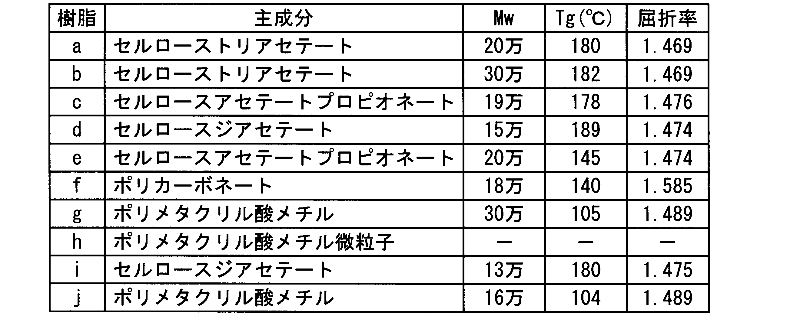
<実施例1>
セルロースアセテートプロピオネート(重量平均分子量20万、ガラス転移温度145℃、屈折率1.474:樹脂e)17.4質量部とセルロースジアセテート(重量平均分子量15万、ガラス転移温度189℃、屈折率1.474:樹脂d)9.4質量部を、塩化メチレン103質量部、エタノール19.6質量部の混合溶媒に溶解してドープを作製した。ベルト流延装置を用い、このドープを2m幅でステンレスベルト上に流延した。ステンレスベルト上で溶媒を蒸発させた後、ウェブをステンレスベルトから剥離し、1.6m幅にスリットした。その後、搬送しながらテンターを用いて、180℃で幅方向に1.03倍、延伸速度200%/分で延伸し、120℃の乾燥ゾーンを多数のロールで搬送させながら乾燥を終了させて巻き取り、平均膜厚40μmの本発明の実施例1のフィルムを得た。
<実施例2、3>
延伸工程における延伸倍率を、それぞれ1.1倍、1.2倍とした以外は実施例1と同様にしてフィルムを作製し、平均膜厚40μmの各々対応する本発明の実施例2及び実施例3のフィルムを得た。
<比較例1、2>
延伸工程における延伸倍率を、それぞれ1.02倍、1.25倍とした以外は実施例1と同様にしてフィルムを作製し、平均膜厚40μmの各々対応する比較例1、比較例2のフィルムを得た。
<実施例4>
ポリメタクリル酸メチル(VB-7103、三菱レイヨン社製、重量平均分子量30万、ガラス転移温度105℃、屈折率1.489:樹脂g)28.4質量部とセルロースアセテートプロピオネート(重量平均分子量19万、ガラス転移温度178℃、屈折率1.476:樹脂c)9.5質量部を、塩化メチレン98.7質量部、エタノール13.5質量部の混合溶媒に溶解してドープを作製した。ベルト流延装置を用い、このドープをステンレスベルト上に流延した。ベルト流延装置を用い、このドープを2m幅でステンレスベルト上に流延した。ステンレスベルト上で溶媒を蒸発させた後、ウェブをステンレスベルトから剥離し、1.6m幅にスリットした。その後、搬送しながらテンターを用いて、110℃で幅方向に1.1倍、延伸速度150%/分で延伸し、100℃の乾燥ゾーンを多数のロールで搬送させながら乾燥を終了させて巻き取り、平均膜厚40μmの本発明の実施例4のフィルムを得た。
<実施例5、6>
延伸工程における延伸温度を、それぞれ140℃、175℃に変更した以外は、実施例4と同様にして作製し、平均膜厚40μmの、各々対応する本発明の実施例5及び実施例6のフィルムを得た。
<比較例3、4>
延伸工程における延伸温度を、それぞれ105℃、180℃に変更した以外は、実施例4と同様にして作製し、平均膜厚40μmの、各々対応する比較例3及び比較例4のフィルムを得た。
[物性測定]
以上のように作製した実施例1~6、比較例1~4のフィルムの算術平均粗さRa、全ヘイズ、内部ヘイズを以下の方法で測定した。結果は表2に示す。
セルロースアセテートプロピオネート(重量平均分子量20万、ガラス転移温度145℃、屈折率1.474:樹脂e)17.4質量部とセルロースジアセテート(重量平均分子量15万、ガラス転移温度189℃、屈折率1.474:樹脂d)9.4質量部を、塩化メチレン103質量部、エタノール19.6質量部の混合溶媒に溶解してドープを作製した。ベルト流延装置を用い、このドープを2m幅でステンレスベルト上に流延した。ステンレスベルト上で溶媒を蒸発させた後、ウェブをステンレスベルトから剥離し、1.6m幅にスリットした。その後、搬送しながらテンターを用いて、180℃で幅方向に1.03倍、延伸速度200%/分で延伸し、120℃の乾燥ゾーンを多数のロールで搬送させながら乾燥を終了させて巻き取り、平均膜厚40μmの本発明の実施例1のフィルムを得た。
<実施例2、3>
延伸工程における延伸倍率を、それぞれ1.1倍、1.2倍とした以外は実施例1と同様にしてフィルムを作製し、平均膜厚40μmの各々対応する本発明の実施例2及び実施例3のフィルムを得た。
<比較例1、2>
延伸工程における延伸倍率を、それぞれ1.02倍、1.25倍とした以外は実施例1と同様にしてフィルムを作製し、平均膜厚40μmの各々対応する比較例1、比較例2のフィルムを得た。
<実施例4>
ポリメタクリル酸メチル(VB-7103、三菱レイヨン社製、重量平均分子量30万、ガラス転移温度105℃、屈折率1.489:樹脂g)28.4質量部とセルロースアセテートプロピオネート(重量平均分子量19万、ガラス転移温度178℃、屈折率1.476:樹脂c)9.5質量部を、塩化メチレン98.7質量部、エタノール13.5質量部の混合溶媒に溶解してドープを作製した。ベルト流延装置を用い、このドープをステンレスベルト上に流延した。ベルト流延装置を用い、このドープを2m幅でステンレスベルト上に流延した。ステンレスベルト上で溶媒を蒸発させた後、ウェブをステンレスベルトから剥離し、1.6m幅にスリットした。その後、搬送しながらテンターを用いて、110℃で幅方向に1.1倍、延伸速度150%/分で延伸し、100℃の乾燥ゾーンを多数のロールで搬送させながら乾燥を終了させて巻き取り、平均膜厚40μmの本発明の実施例4のフィルムを得た。
<実施例5、6>
延伸工程における延伸温度を、それぞれ140℃、175℃に変更した以外は、実施例4と同様にして作製し、平均膜厚40μmの、各々対応する本発明の実施例5及び実施例6のフィルムを得た。
<比較例3、4>
延伸工程における延伸温度を、それぞれ105℃、180℃に変更した以外は、実施例4と同様にして作製し、平均膜厚40μmの、各々対応する比較例3及び比較例4のフィルムを得た。
[物性測定]
以上のように作製した実施例1~6、比較例1~4のフィルムの算術平均粗さRa、全ヘイズ、内部ヘイズを以下の方法で測定した。結果は表2に示す。
(表面形状観察及び算術平均粗さRa)
Olympus(株)製3D測定レーザー顕微鏡LEXT OLS4000を用いて作製したフィルムの表面を観察したところ、全てのフィルムで海島構造による凹凸を形成していた。さらにこの装置を使って解析を行い、JIS B 0601-2001に則った算術平均粗さRaを求めた。
Olympus(株)製3D測定レーザー顕微鏡LEXT OLS4000を用いて作製したフィルムの表面を観察したところ、全てのフィルムで海島構造による凹凸を形成していた。さらにこの装置を使って解析を行い、JIS B 0601-2001に則った算術平均粗さRaを求めた。
(ヘイズ値)
日本電色工業(株)製NDH2000を用いて、各々のフィルム一枚の全ヘイズを測定した。また、フィルムの両表面を、グリセリン(屈折率1.47)を介してガラス板で挟んだ状態で、フィルムの内部ヘイズを測定した。
[評価]
以上のように作製した実施例1~6及び比較例1~4のフィルムについて、以下の方法で微粒子脱落性、モアレ解消能、脆性、正面輝度の評価を行った。結果は表2に示す。
日本電色工業(株)製NDH2000を用いて、各々のフィルム一枚の全ヘイズを測定した。また、フィルムの両表面を、グリセリン(屈折率1.47)を介してガラス板で挟んだ状態で、フィルムの内部ヘイズを測定した。
[評価]
以上のように作製した実施例1~6及び比較例1~4のフィルムについて、以下の方法で微粒子脱落性、モアレ解消能、脆性、正面輝度の評価を行った。結果は表2に示す。
以下の評価方法の説明において「評価フィルム」とは、実施例1~6及び比較例1~4で作製したフィルムのことを指す。
〈微粒子脱落性〉
粒子の脱落性は、新東科学(株)製の表面性測定機(トライボステーションTYPE32)を用いて評価した。まず、表面性測定機の摩擦子摺動面に不織布(ベンコット、旭化成(株)製)を設置し、その下に対向するように評価フィルムを載置し、200gの荷重をかけて10回往復させた。その後、不織布の表面における脱落微粒子の付着状況を光学顕微鏡(450倍)で観察し、フィルムの微粒子脱落性を下記の基準で評価した。
◎:脱落微粒子が全く観察されなかった。
×:脱落微粒子が観察された。
粒子の脱落性は、新東科学(株)製の表面性測定機(トライボステーションTYPE32)を用いて評価した。まず、表面性測定機の摩擦子摺動面に不織布(ベンコット、旭化成(株)製)を設置し、その下に対向するように評価フィルムを載置し、200gの荷重をかけて10回往復させた。その後、不織布の表面における脱落微粒子の付着状況を光学顕微鏡(450倍)で観察し、フィルムの微粒子脱落性を下記の基準で評価した。
◎:脱落微粒子が全く観察されなかった。
×:脱落微粒子が観察された。
〈モアレ解消能〉
市販のノートパソコン(Sumsung製R430)を分解してバックライトユニットを取り出し、組み込まれていたプリズムシート二枚を取りだした。シャーカステンの上にこの二枚のプリズムシートを、バックライトユニットに組み込まれていたのと同じ順、同じ位置関係になるように配置した。この状態で、暗室内で見ると、強いモアレ縞が観察された。図4に示すように、表面のプリズムシートのさらに上に、10cm×10cmの大きさに切った評価フィルムを、フィルムの凹凸面がプリズムシートに向き合うように設置し、暗室内で観察し、モアレ縞の解消具合を下記の基準で評価した。△と×の基準に用いた「市販品」とは、上記ノートパソコンのリア側(バックライト側)偏光板用の保護フィルムとして用いられていたフィルムのうち、バックライトと隣接するように配置されていた防眩フィルムであり、上記ノートパソコンのリア側偏光板を液晶セルから剥離し、純水に4時間浸漬した後にフィルムから偏光子を剥がして取りだしたものを十分に乾燥し、23℃・55%RHに調湿した後に用いた。
◎:モアレは完全に消えている
○:モアレはやや残っているが、市販品と同程度である
×:モアレが残り、市販品以下のレベルである
〈脆性評価〉
評価フィルムを100mm(縦)×10mm(幅)で切り出し、縦方向の中央部で山折り、谷折りと二つにそれぞれ1回ずつ折り曲げ、この評価を4回測定して下記基準で評価した。なお、ここでの評価の折れるとは、割れて二つ以上のピースに分離したことを表す。
◎:4回とも折れない
○:4回のうち1回折れる
×:4回のうち2回以上折れる
〈正面輝度〉
以下の手順で偏光板、液晶表示装置を作製した後、正面輝度を評価した。
(位相差フィルム1の製造)
〈微粒子添加液1〉
メチレンクロライドを入れた溶解タンクに十分攪拌しながら、微粒子分散液1をゆっくりと添加した。更に、二次粒子の粒径が所定の大きさとなるようにアトライターにて分散を行った。これを日本精線(株)製のファインメットNFで濾過し、微粒子添加液1を調製した。
市販のノートパソコン(Sumsung製R430)を分解してバックライトユニットを取り出し、組み込まれていたプリズムシート二枚を取りだした。シャーカステンの上にこの二枚のプリズムシートを、バックライトユニットに組み込まれていたのと同じ順、同じ位置関係になるように配置した。この状態で、暗室内で見ると、強いモアレ縞が観察された。図4に示すように、表面のプリズムシートのさらに上に、10cm×10cmの大きさに切った評価フィルムを、フィルムの凹凸面がプリズムシートに向き合うように設置し、暗室内で観察し、モアレ縞の解消具合を下記の基準で評価した。△と×の基準に用いた「市販品」とは、上記ノートパソコンのリア側(バックライト側)偏光板用の保護フィルムとして用いられていたフィルムのうち、バックライトと隣接するように配置されていた防眩フィルムであり、上記ノートパソコンのリア側偏光板を液晶セルから剥離し、純水に4時間浸漬した後にフィルムから偏光子を剥がして取りだしたものを十分に乾燥し、23℃・55%RHに調湿した後に用いた。
◎:モアレは完全に消えている
○:モアレはやや残っているが、市販品と同程度である
×:モアレが残り、市販品以下のレベルである
〈脆性評価〉
評価フィルムを100mm(縦)×10mm(幅)で切り出し、縦方向の中央部で山折り、谷折りと二つにそれぞれ1回ずつ折り曲げ、この評価を4回測定して下記基準で評価した。なお、ここでの評価の折れるとは、割れて二つ以上のピースに分離したことを表す。
◎:4回とも折れない
○:4回のうち1回折れる
×:4回のうち2回以上折れる
〈正面輝度〉
以下の手順で偏光板、液晶表示装置を作製した後、正面輝度を評価した。
(位相差フィルム1の製造)
〈微粒子添加液1〉
メチレンクロライドを入れた溶解タンクに十分攪拌しながら、微粒子分散液1をゆっくりと添加した。更に、二次粒子の粒径が所定の大きさとなるようにアトライターにて分散を行った。これを日本精線(株)製のファインメットNFで濾過し、微粒子添加液1を調製した。
メチレンクロライド 99質量部
微粒子分散液1 5質量部
下記組成の主ドープを調製した。まず加圧溶解タンクにメチレンクロライドとエタノールを添加した。溶剤の入った加圧溶解タンクにセルロースアセテートを攪拌しながら投入した。これを加熱し、攪拌しながら、完全に溶解し。これを安積濾紙(株)製の安積濾紙No.244を使用して濾過し、主ドープを調製した。
微粒子分散液1 5質量部
下記組成の主ドープを調製した。まず加圧溶解タンクにメチレンクロライドとエタノールを添加した。溶剤の入った加圧溶解タンクにセルロースアセテートを攪拌しながら投入した。これを加熱し、攪拌しながら、完全に溶解し。これを安積濾紙(株)製の安積濾紙No.244を使用して濾過し、主ドープを調製した。
〈主ドープの組成〉
メチレンクロライド 340質量部
エタノール 64質量部
セルロースアセテートプロピオネート
(総置換度2.46、プロピオニル置換度0.88) 100質量部
糖エステル化合物A(平均置換度5.5) 10.0質量部
以下で合成したポリエステルP 2.5質量部
紫外線吸収剤(チヌビン928(BASFジャパン(株)製))
2.3質量部
微粒子添加液1 1質量部
メチレンクロライド 340質量部
エタノール 64質量部
セルロースアセテートプロピオネート
(総置換度2.46、プロピオニル置換度0.88) 100質量部
糖エステル化合物A(平均置換度5.5) 10.0質量部
以下で合成したポリエステルP 2.5質量部
紫外線吸収剤(チヌビン928(BASFジャパン(株)製))
2.3質量部
微粒子添加液1 1質量部

(ポリエステルPの合成)
窒素雰囲気下、テレフタル酸ジメチル4.85g、1,2-プロピレングリコール4.4g、p-トルイル酸6.8g、テトライソプロピルチタネート10mgを混合し、140℃で2時間攪拌を行った後、更に210℃で16時間攪拌を行った。次に、170℃まで降温し、未反応物の1,2-プロピレングリコールを減圧留去することにより、ポリエステルPを得た。
窒素雰囲気下、テレフタル酸ジメチル4.85g、1,2-プロピレングリコール4.4g、p-トルイル酸6.8g、テトライソプロピルチタネート10mgを混合し、140℃で2時間攪拌を行った後、更に210℃で16時間攪拌を行った。次に、170℃まで降温し、未反応物の1,2-プロピレングリコールを減圧留去することにより、ポリエステルPを得た。
酸価 :0.1
数平均分子量:490
分散度 :1.4
分子量300~1800の成分含有率:90%
ヒドロキシ(水酸基)価:0.1
ヒドロキシ基(水酸基)含有量:0.04%
上記組成物を密閉容器に投入し、攪拌しながら溶解してドープを調製した。次いで、無端ベルト流延装置を用い、ドープを温度33℃、2000mm幅でステンレスベルト支持体上に均一に流延した。ステンレスベルトの温度は30℃に制御した。
数平均分子量:490
分散度 :1.4
分子量300~1800の成分含有率:90%
ヒドロキシ(水酸基)価:0.1
ヒドロキシ基(水酸基)含有量:0.04%
上記組成物を密閉容器に投入し、攪拌しながら溶解してドープを調製した。次いで、無端ベルト流延装置を用い、ドープを温度33℃、2000mm幅でステンレスベルト支持体上に均一に流延した。ステンレスベルトの温度は30℃に制御した。
ステンレスベルト支持体上で、流延(キャスト)したフィルム中の残留溶媒量が75%になるまで溶媒を蒸発させ、次いで剥離張力130N/mで、ステンレスベルト支持体上から剥離した。
その後テンター延伸装置を用いて延伸を行い、次いで130℃に設定された乾燥ゾーンで30分間搬送させて乾燥を行い、幅2m、かつ端部に幅1cm、高さ8μmのナーリングを有する膜厚40μmの光学フィルム1を作製し、5000mで巻き取った。
光学フィルム1のリターデーション値Ro(590)、Rt(590)は、各々20nm、110nmであった。
(偏光板化)
以下の工程1~6に従って偏光子及び評価サンプルを使った偏光板を作製した。
以下の工程1~6に従って偏光子及び評価サンプルを使った偏光板を作製した。
工程1
厚さ50μmのポリビニルアルコールフィルムを製膜方向に一軸延伸(温度110℃、延伸倍率5倍)した。これをヨウ素0.075g、ヨウ化カリウム6g、水100gの比率からなる水溶液に60秒間浸漬し、次いでヨウ化カリウム6g、ホウ酸7.5g、水100gの比率からなる68℃の水溶液に浸漬した。これを水洗、乾燥し偏光子を得た。この偏光子は吸収軸が製膜方向にあった。
厚さ50μmのポリビニルアルコールフィルムを製膜方向に一軸延伸(温度110℃、延伸倍率5倍)した。これをヨウ素0.075g、ヨウ化カリウム6g、水100gの比率からなる水溶液に60秒間浸漬し、次いでヨウ化カリウム6g、ホウ酸7.5g、水100gの比率からなる68℃の水溶液に浸漬した。これを水洗、乾燥し偏光子を得た。この偏光子は吸収軸が製膜方向にあった。
工程2
偏光板用保護フィルムとして、作製した評価フィルムを50℃の4規定の水酸化カリウム水溶液に60秒間浸漬し、次いで水洗、乾燥して偏光子と貼合する面を鹸化した。
偏光板用保護フィルムとして、作製した評価フィルムを50℃の4規定の水酸化カリウム水溶液に60秒間浸漬し、次いで水洗、乾燥して偏光子と貼合する面を鹸化した。
同様に、反対側の偏光板用保護フィルムとして、上記で作製した位相差フィルム1の鹸化も行った。
工程3
前記偏光子を固形分2質量%のポリビニルアルコール接着剤槽中に1~2秒浸漬した。
前記偏光子を固形分2質量%のポリビニルアルコール接着剤槽中に1~2秒浸漬した。
工程4
工程3で偏光子に付着した過剰の接着剤を軽く拭き除き、これを工程2で処理した評価フィルムの貼合面上にのせ、更に反対側の偏光板用保護フィルムとして、工程2で処理した位相差フィルム1の鹸化した面が偏光子に接するように積層し、偏光板とした。
工程3で偏光子に付着した過剰の接着剤を軽く拭き除き、これを工程2で処理した評価フィルムの貼合面上にのせ、更に反対側の偏光板用保護フィルムとして、工程2で処理した位相差フィルム1の鹸化した面が偏光子に接するように積層し、偏光板とした。
工程5
工程4でフィルムと偏光子を積層した偏光板を、圧力20~30N/cm2、搬送スピードは約2m/分で貼合した。
工程4でフィルムと偏光子を積層した偏光板を、圧力20~30N/cm2、搬送スピードは約2m/分で貼合した。
工程6
80℃の乾燥機中に工程5で作製した偏光子と評価フィルムと光学フィルム1とをロールtoロールで貼り合わせた試料を2分間乾燥し、実施例1~6及び比較例1~4に各々対応する偏光板を作製した。
80℃の乾燥機中に工程5で作製した偏光子と評価フィルムと光学フィルム1とをロールtoロールで貼り合わせた試料を2分間乾燥し、実施例1~6及び比較例1~4に各々対応する偏光板を作製した。
(表示装置の作製)
市販の液晶モニタ(Samsung製、SyncMaster743BM)のリア側偏光板を剥がし、代わりに、上記で作製した偏光板を貼合した。ただし、液晶セルに貼合する際は、評価フィルムの面がバックライト側に向く配置になるように、かつ、あらかじめ貼合されていた偏光板と同一の方向に吸収軸が向くように貼合した。バックライトユニットは、光源側から順に、導光板/下拡散シート/プリズムシート/プリズムシートの構成になっていた。実施例1~6及び比較例1~4のフィルムに各々対応する、本発明の液晶表示装置1~6及び比較の液晶表示装置1~4を作製した。
市販の液晶モニタ(Samsung製、SyncMaster743BM)のリア側偏光板を剥がし、代わりに、上記で作製した偏光板を貼合した。ただし、液晶セルに貼合する際は、評価フィルムの面がバックライト側に向く配置になるように、かつ、あらかじめ貼合されていた偏光板と同一の方向に吸収軸が向くように貼合した。バックライトユニットは、光源側から順に、導光板/下拡散シート/プリズムシート/プリズムシートの構成になっていた。実施例1~6及び比較例1~4のフィルムに各々対応する、本発明の液晶表示装置1~6及び比較の液晶表示装置1~4を作製した。
(正面輝度の評価)
液晶表示装置の光源の電源を入れ、パネル面が床面に対して垂直になるように設置し、23℃55%RH環境下で120分点灯させた。その後、コニカミノルタ製分光放射輝度計CS2000を用いて、暗室内にてモニタの中央部の正面輝度を測定した(図5参照)。
液晶表示装置の光源の電源を入れ、パネル面が床面に対して垂直になるように設置し、23℃55%RH環境下で120分点灯させた。その後、コニカミノルタ製分光放射輝度計CS2000を用いて、暗室内にてモニタの中央部の正面輝度を測定した(図5参照)。
評価の基準には市販のセルロースエステルフィルム4UY(コニカミノルタオプト(株)製)を用い、同様の方法で作製した4UYの偏光板をリア側偏光板に用いた場合の正面輝度に対して、評価フィルムの正面輝度の割合を算出し、以下の基準で評価した。
◎:4UYの正面輝度の99%以上
○:4UYの正面輝度の90%以上99%より小さい
×:4UYの正面輝度の90%より小さい
上記実施例1~6及び比較例1~4のフィルムについての測定及び評価結果をまとめて表2に示す。
◎:4UYの正面輝度の99%以上
○:4UYの正面輝度の90%以上99%より小さい
×:4UYの正面輝度の90%より小さい
上記実施例1~6及び比較例1~4のフィルムについての測定及び評価結果をまとめて表2に示す。

本発明の製造方法で作製された実施例1~6のフィルムは、脆性の問題もなく、表示装置化した場合の正面輝度とモアレ解消能を両立できるフィルムであることがわかった。
<実施例7>
セルロースアセテートプロピオネート(重量平均分子量20万、ガラス転移温度145℃、屈折率1.474:樹脂e)17.4質量部とセルロースジアセテート(重量平均分子量13万、ガラス転移温度180℃、屈折率1.475:樹脂i)9.4質量部を、塩化メチレン103質量部、エタノール19.6質量部の混合溶媒に溶解してドープを作製した。ベルト流延装置を用い、このドープを2m幅でステンレスベルト上に流延した。ステンレスベルト上で溶媒を蒸発させた後、ウェブをステンレスベルトから剥離し、1.6m幅にスリットした。その後、搬送しながらテンターを用いて、170℃で幅方向に1.1倍、延伸速度150%/分で延伸し、120℃の乾燥ゾーンを多数のロールで搬送させながら乾燥を終了させて巻き取り、平均膜厚45μmの本発明の実施例7のフィルムを得た。
<比較例5>
ポリカーボネート(重量平均分子量18万、ガラス転移温度140℃、屈折率1.585:樹脂f)17.4質量部とセルロースジアセテート(重量平均分子量15万、ガラス転移温度189℃、屈折率1.474:樹脂d)9.4質量部を、塩化メチレン119.6質量部に溶解してドープを作製した。ベルト流延装置を用い、このドープを2m幅でステンレスベルト上に流延した。ステンレスベルト上で溶媒を蒸発させた後、ウェブをステンレスベルトから剥離し、1.6m幅にスリットした。その後、搬送しながらテンターを用いて、180℃で幅方向に1.1倍、延伸速度150%/分で延伸し、120℃の乾燥ゾーンを多数のロールで搬送させながら乾燥を終了させて巻き取り、平均膜厚45μmの比較例5のフィルムを得た。
<実施例8>
延伸工程における延伸速度を、350%/分に変更した以外は、実施例5と同様にして作製し、平均膜厚40μmの本発明の実施例8のフィルムを得た。
<実施例9>
ポリメタクリル酸メチル(重量平均分子量16万、ガラス転移温度104℃、屈折率1.489:樹脂j)28.4質量部とセルロースジアセテート(重量平均分子量15万、ガラス転移温度189℃、屈折率1.474:樹脂d)9.5質量部を、塩化メチレン98.7質量部、エタノール13.5質量部の混合溶媒に溶解してドープを作製した。ベルト流延装置を用い、このドープをステンレスベルト上に流延した。ベルト流延装置を用い、このドープを2m幅でステンレスベルト上に流延した。ステンレスベルト上で溶媒を蒸発させた後、ウェブをステンレスベルトから剥離し、1.6m幅にスリットした。その後、搬送しながらテンターを用いて、140℃で幅方向に1.1倍、延伸速度200%/分で延伸し、100℃の乾燥ゾーンを多数のロールで搬送させながら乾燥を終了させて巻き取り、平均膜厚40μmの本発明の実施例9のフィルムを得た。
<比較例6>
セルローストリアセテート(重量平均分子量20万、ガラス転移温度180℃、屈折率1.469;樹脂a)3質量部とポリメタクリル酸メチル(重量平均分子量30万、ガラス転移温度105℃、屈折率1.489:樹脂g)3質量部とをアセトン94質量部に溶解してドープを作製した。このドープをガラス板上に流延した後、30℃のオーブン内で3分間放置してから剥離し、さらに120℃で20分間乾燥することにより、平均膜厚40μmの比較例6のフィルムを得た。
<比較例7>
セルローストリアセテート(重量平均分子量30万、ガラス転移温度182℃、屈折率1.469:樹脂b)60質量部を塩化メチレン/メタノール=9/1(質量比)の混合溶媒900質量部に溶解した。この溶液に架橋ポリメタクリル酸メチル微粒子(PMMA、積水化成工業社製、MBX-2AB;樹脂h)40質量部を加えて混練し、ガラス板上に流延した後、25℃にて3分間放置してから剥離し、さらに120℃で20分間乾燥することにより、平均膜厚45μmの比較例7のフィルムを得た。
[物性測定]
実施例7~9、比較例5~7のフィルムの算術平均粗さRa、全ヘイズ、内部ヘイズを前術の方法で測定した。結果は表3に示す。
[評価]
実施例7~9及び比較例5~7のフィルムについて、前述の方法で微粒子脱落性、モアレ解消能、脆性、表示装置化した場合の正面輝度の評価を行った。結果は表3に示す。
<実施例7>
セルロースアセテートプロピオネート(重量平均分子量20万、ガラス転移温度145℃、屈折率1.474:樹脂e)17.4質量部とセルロースジアセテート(重量平均分子量13万、ガラス転移温度180℃、屈折率1.475:樹脂i)9.4質量部を、塩化メチレン103質量部、エタノール19.6質量部の混合溶媒に溶解してドープを作製した。ベルト流延装置を用い、このドープを2m幅でステンレスベルト上に流延した。ステンレスベルト上で溶媒を蒸発させた後、ウェブをステンレスベルトから剥離し、1.6m幅にスリットした。その後、搬送しながらテンターを用いて、170℃で幅方向に1.1倍、延伸速度150%/分で延伸し、120℃の乾燥ゾーンを多数のロールで搬送させながら乾燥を終了させて巻き取り、平均膜厚45μmの本発明の実施例7のフィルムを得た。
<比較例5>
ポリカーボネート(重量平均分子量18万、ガラス転移温度140℃、屈折率1.585:樹脂f)17.4質量部とセルロースジアセテート(重量平均分子量15万、ガラス転移温度189℃、屈折率1.474:樹脂d)9.4質量部を、塩化メチレン119.6質量部に溶解してドープを作製した。ベルト流延装置を用い、このドープを2m幅でステンレスベルト上に流延した。ステンレスベルト上で溶媒を蒸発させた後、ウェブをステンレスベルトから剥離し、1.6m幅にスリットした。その後、搬送しながらテンターを用いて、180℃で幅方向に1.1倍、延伸速度150%/分で延伸し、120℃の乾燥ゾーンを多数のロールで搬送させながら乾燥を終了させて巻き取り、平均膜厚45μmの比較例5のフィルムを得た。
<実施例8>
延伸工程における延伸速度を、350%/分に変更した以外は、実施例5と同様にして作製し、平均膜厚40μmの本発明の実施例8のフィルムを得た。
<実施例9>
ポリメタクリル酸メチル(重量平均分子量16万、ガラス転移温度104℃、屈折率1.489:樹脂j)28.4質量部とセルロースジアセテート(重量平均分子量15万、ガラス転移温度189℃、屈折率1.474:樹脂d)9.5質量部を、塩化メチレン98.7質量部、エタノール13.5質量部の混合溶媒に溶解してドープを作製した。ベルト流延装置を用い、このドープをステンレスベルト上に流延した。ベルト流延装置を用い、このドープを2m幅でステンレスベルト上に流延した。ステンレスベルト上で溶媒を蒸発させた後、ウェブをステンレスベルトから剥離し、1.6m幅にスリットした。その後、搬送しながらテンターを用いて、140℃で幅方向に1.1倍、延伸速度200%/分で延伸し、100℃の乾燥ゾーンを多数のロールで搬送させながら乾燥を終了させて巻き取り、平均膜厚40μmの本発明の実施例9のフィルムを得た。
<比較例6>
セルローストリアセテート(重量平均分子量20万、ガラス転移温度180℃、屈折率1.469;樹脂a)3質量部とポリメタクリル酸メチル(重量平均分子量30万、ガラス転移温度105℃、屈折率1.489:樹脂g)3質量部とをアセトン94質量部に溶解してドープを作製した。このドープをガラス板上に流延した後、30℃のオーブン内で3分間放置してから剥離し、さらに120℃で20分間乾燥することにより、平均膜厚40μmの比較例6のフィルムを得た。
<比較例7>
セルローストリアセテート(重量平均分子量30万、ガラス転移温度182℃、屈折率1.469:樹脂b)60質量部を塩化メチレン/メタノール=9/1(質量比)の混合溶媒900質量部に溶解した。この溶液に架橋ポリメタクリル酸メチル微粒子(PMMA、積水化成工業社製、MBX-2AB;樹脂h)40質量部を加えて混練し、ガラス板上に流延した後、25℃にて3分間放置してから剥離し、さらに120℃で20分間乾燥することにより、平均膜厚45μmの比較例7のフィルムを得た。
[物性測定]
実施例7~9、比較例5~7のフィルムの算術平均粗さRa、全ヘイズ、内部ヘイズを前術の方法で測定した。結果は表3に示す。
[評価]
実施例7~9及び比較例5~7のフィルムについて、前述の方法で微粒子脱落性、モアレ解消能、脆性、表示装置化した場合の正面輝度の評価を行った。結果は表3に示す。
上記実施例7~9及び比較例5~7のフィルムについての測定及び評価結果をまとめて表3に示す。

本発明の製造方法で作製された実施例7~9のフィルムは、脆性の問題もなく、表示装置化した場合の正面輝度とモアレ解消能を両立できるフィルムであることがわかった。
本発明は、液晶表示装置のバックライト側偏光板用保護フィルムの製造に用いることができ、さらに、当該製造方法にて製造された偏光板用保護フィルムが具備された偏光板及び液晶表示装置に利用できる。
1 溶解釜
3、6、12、15 濾過器
4、13 ストックタンク
5、14 送液ポンプ
8、16 導管
10 紫外線吸収剤仕込釜
20 合流管
21 混合機
30 ダイ
31 金属支持体
32 ウェブ
33 剥離位置
34 テンター装置
35 ロール乾燥装置
41 粒子仕込釜
42 ストックタンク
43 ポンプ
44 濾過器
1a 光源
2a 発光光源
3a 下拡散シート(又は拡散板)
4a 集光シート(プリズムシート、レンズシート)
5a 上拡散シート
6a バックライトユニット
7a 液晶セル
8a 透明基板(ガラス、プラスチック)
9a 保護フィルム(又は位相差フィルム)
10a 偏光子
11a 保護フィルム
12a 液晶パネル
13a 導光板
14a 本発明の偏光板用保護フィルム(拡散能付き)
1b A面
2b B面
3b 評価フィルム
4b プリズムシート
5b プリズムシート
6b シャーカステン
1c 液晶モニタ
2c 導光板
3c 下拡散シート
4c プリズムシート
5c 評価フィルム
6c 固定板
7c ガラス板
8c 分光放射輝度計
3、6、12、15 濾過器
4、13 ストックタンク
5、14 送液ポンプ
8、16 導管
10 紫外線吸収剤仕込釜
20 合流管
21 混合機
30 ダイ
31 金属支持体
32 ウェブ
33 剥離位置
34 テンター装置
35 ロール乾燥装置
41 粒子仕込釜
42 ストックタンク
43 ポンプ
44 濾過器
1a 光源
2a 発光光源
3a 下拡散シート(又は拡散板)
4a 集光シート(プリズムシート、レンズシート)
5a 上拡散シート
6a バックライトユニット
7a 液晶セル
8a 透明基板(ガラス、プラスチック)
9a 保護フィルム(又は位相差フィルム)
10a 偏光子
11a 保護フィルム
12a 液晶パネル
13a 導光板
14a 本発明の偏光板用保護フィルム(拡散能付き)
1b A面
2b B面
3b 評価フィルム
4b プリズムシート
5b プリズムシート
6b シャーカステン
1c 液晶モニタ
2c 導光板
3c 下拡散シート
4c プリズムシート
5c 評価フィルム
6c 固定板
7c ガラス板
8c 分光放射輝度計
Claims (7)
- 海に相当する連続相と島に相当する分散相とからなる海島構造を有する偏光板用保護フィルムの製造方法であって、当該島を構成する主成分となる樹脂Aのガラス転移温度Tg(A)と、当該海を構成する主成分となる樹脂Bのガラス転移温度Tg(B)の差(Tg(A)-Tg(B))が10℃超であり、当該樹脂Aと当該樹脂Bの屈折率の差の絶対値が0.08以下であり、かつ下記工程(a)~(d)を有することを特徴とする偏光板用保護フィルムの製造方法。
工程(a):前記樹脂Aと樹脂Bを含有するドープを形成する工程
工程(b):前記ドープを流延用支持体上に流延してウェブを形成する工程
工程(c):前記ウェブから有機溶媒を蒸発させる乾燥工程
工程(d):延伸温度TがTg(B)<T<Tg(A)となる温度で、1.03~1.20倍の範囲内の倍率で前記ウェブを延伸する延伸工程 - 下記式(I)で求められる前記延伸工程における延伸速度が、20~300%/分の範囲内にあることを特徴とする請求項1に記載の偏光板用保護フィルムの製造方法。
式(I):延伸速度(%/分)={(延伸後幅手寸法/延伸前幅手寸法)-1}×100(%)/延伸にかかる時間(分) - 前記樹脂A及び樹脂Bの少なくともいずれか一方の重量平均分子量(Mw)が、180000以上であることを特徴とする請求項1又は請求項2に記載の偏光板用保護フィルムの製造方法。
- 請求項1から請求項3までのいずれか一項に記載の偏光板用保護フィルムの製造方法によって製造された偏光板用保護フィルムであって、当該偏光板用保護フィルムの少なくとも一方の表面の算術平均粗さRaが0.08~2.0μmの範囲内にあることを特徴とする偏光板用保護フィルム。
- 前記偏光板用保護フィルム一枚の全ヘイズ値が20~80%の範囲内にあり、かつ、(全ヘイズ値)-(表面ヘイズ値)で求められる内部ヘイズ値が0.15~30%の範囲内にあることを特徴とする請求項4に記載の偏光板用保護フィルム。
- 請求項1から請求項3までのいずれか一項に記載の偏光板用保護フィルムの製造方法によって製造された偏光板用保護フィルムが具備されていることを特徴とする偏光板。
- 請求項1から請求項3までのいずれか一項に記載の偏光板用保護フィルムの製造方法によって製造された偏光板用保護フィルムが具備されていることを特徴とする液晶表示装置。
Priority Applications (1)
| Application Number | Priority Date | Filing Date | Title |
|---|---|---|---|
| JP2013512020A JP5942988B2 (ja) | 2011-04-25 | 2012-04-17 | 偏光板用保護フィルムの製造方法、偏光板用保護フィルム、偏光板及び液晶表示装置 |
Applications Claiming Priority (2)
| Application Number | Priority Date | Filing Date | Title |
|---|---|---|---|
| JP2011-096864 | 2011-04-25 | ||
| JP2011096864 | 2011-04-25 |
Publications (1)
| Publication Number | Publication Date |
|---|---|
| WO2012147562A1 true WO2012147562A1 (ja) | 2012-11-01 |
Family
ID=47072084
Family Applications (1)
| Application Number | Title | Priority Date | Filing Date |
|---|---|---|---|
| PCT/JP2012/060336 Ceased WO2012147562A1 (ja) | 2011-04-25 | 2012-04-17 | 偏光板用保護フィルムの製造方法、偏光板用保護フィルム、偏光板及び液晶表示装置 |
Country Status (2)
| Country | Link |
|---|---|
| JP (1) | JP5942988B2 (ja) |
| WO (1) | WO2012147562A1 (ja) |
Cited By (2)
| Publication number | Priority date | Publication date | Assignee | Title |
|---|---|---|---|---|
| JPWO2012128239A1 (ja) * | 2011-03-22 | 2014-07-24 | コニカミノルタ株式会社 | 偏光板用保護フィルム、その製造方法、偏光板、及び液晶表示装置 |
| JP2017068223A (ja) * | 2015-10-02 | 2017-04-06 | 住友化学株式会社 | 偏光板用保護フィルム |
Citations (6)
| Publication number | Priority date | Publication date | Assignee | Title |
|---|---|---|---|---|
| JP2004131728A (ja) * | 2002-09-18 | 2004-04-30 | Toray Ind Inc | 二軸配向ポリエステルフィルム |
| JP2007178504A (ja) * | 2005-12-27 | 2007-07-12 | Toray Ind Inc | 表示装置用フィルムおよびその製造方法 |
| WO2008018279A1 (fr) * | 2006-08-07 | 2008-02-14 | Konica Minolta Opto, Inc. | film de protection de plaque de polarisation, et plaque de polarisation et dispositif d'affichage à cristaux liquides utilisant le film de protection de plaque de polarisation |
| JP2008107499A (ja) * | 2006-10-24 | 2008-05-08 | Fujifilm Corp | 偏光板及び液晶表示装置 |
| JP2009221324A (ja) * | 2008-03-14 | 2009-10-01 | Soken Chem & Eng Co Ltd | 光学部材用粘着剤およびこれを利用した光学部材用保護フィルム |
| JP2011008012A (ja) * | 2009-06-25 | 2011-01-13 | Teijin Chem Ltd | 光拡散板 |
Family Cites Families (3)
| Publication number | Priority date | Publication date | Assignee | Title |
|---|---|---|---|---|
| JP4904979B2 (ja) * | 2006-08-11 | 2012-03-28 | Dic株式会社 | 積層体 |
| JP4379547B2 (ja) * | 2007-10-13 | 2009-12-09 | コニカミノルタオプト株式会社 | 光学フィルムの製造方法 |
| WO2012128239A1 (ja) * | 2011-03-22 | 2012-09-27 | コニカミノルタアドバンストレイヤー株式会社 | 偏光板用保護フィルム、その製造方法、偏光板、及び液晶表示装置 |
-
2012
- 2012-04-17 WO PCT/JP2012/060336 patent/WO2012147562A1/ja not_active Ceased
- 2012-04-17 JP JP2013512020A patent/JP5942988B2/ja active Active
Patent Citations (6)
| Publication number | Priority date | Publication date | Assignee | Title |
|---|---|---|---|---|
| JP2004131728A (ja) * | 2002-09-18 | 2004-04-30 | Toray Ind Inc | 二軸配向ポリエステルフィルム |
| JP2007178504A (ja) * | 2005-12-27 | 2007-07-12 | Toray Ind Inc | 表示装置用フィルムおよびその製造方法 |
| WO2008018279A1 (fr) * | 2006-08-07 | 2008-02-14 | Konica Minolta Opto, Inc. | film de protection de plaque de polarisation, et plaque de polarisation et dispositif d'affichage à cristaux liquides utilisant le film de protection de plaque de polarisation |
| JP2008107499A (ja) * | 2006-10-24 | 2008-05-08 | Fujifilm Corp | 偏光板及び液晶表示装置 |
| JP2009221324A (ja) * | 2008-03-14 | 2009-10-01 | Soken Chem & Eng Co Ltd | 光学部材用粘着剤およびこれを利用した光学部材用保護フィルム |
| JP2011008012A (ja) * | 2009-06-25 | 2011-01-13 | Teijin Chem Ltd | 光拡散板 |
Cited By (3)
| Publication number | Priority date | Publication date | Assignee | Title |
|---|---|---|---|---|
| JPWO2012128239A1 (ja) * | 2011-03-22 | 2014-07-24 | コニカミノルタ株式会社 | 偏光板用保護フィルム、その製造方法、偏光板、及び液晶表示装置 |
| JP2017068223A (ja) * | 2015-10-02 | 2017-04-06 | 住友化学株式会社 | 偏光板用保護フィルム |
| CN106802443A (zh) * | 2015-10-02 | 2017-06-06 | 住友化学株式会社 | 偏振板用保护膜 |
Also Published As
| Publication number | Publication date |
|---|---|
| JP5942988B2 (ja) | 2016-06-29 |
| JPWO2012147562A1 (ja) | 2014-07-28 |
Similar Documents
| Publication | Publication Date | Title |
|---|---|---|
| JP5521552B2 (ja) | アクリル樹脂含有フィルム、それを用いた偏光板及び液晶表示装置 | |
| KR101390618B1 (ko) | 광학 필름 | |
| JP5402925B2 (ja) | 偏光板及び液晶表示装置 | |
| JP5831540B2 (ja) | 偏光板用保護フィルム、その製造方法、偏光板、及び液晶表示装置 | |
| JP2013109116A (ja) | 偏光膜保護フィルムの製造方法、偏光膜保護フィルム、偏光板及びそれを用いた液晶表示装置 | |
| TW201107396A (en) | Optical element | |
| WO2013080847A1 (ja) | アクリル樹脂含有フィルムの製造方法 | |
| JP5533858B2 (ja) | 光学フィルム、それを用いた偏光板及び液晶表示装置 | |
| WO2012026192A1 (ja) | ハードコートフィルム、偏光板、及び液晶表示装置 | |
| JP5310724B2 (ja) | 偏光板、液晶表示装置 | |
| JP5533857B2 (ja) | 光学フィルム、それを用いた偏光板及び液晶表示装置 | |
| JP5980465B2 (ja) | 偏光板及びそれを用いた液晶表示装置 | |
| JP5942988B2 (ja) | 偏光板用保護フィルムの製造方法、偏光板用保護フィルム、偏光板及び液晶表示装置 | |
| JP5045539B2 (ja) | 偏光板用保護フィルム、偏光板及び液晶表示装置 | |
| JP5720509B2 (ja) | 面光源装置 | |
| WO2011055590A1 (ja) | 液晶偏光板用保護フィルムロール及びその製造方法 | |
| WO2009119268A1 (ja) | アクリル樹脂含有フィルム、アクリル樹脂含有フィルム製造方法、それを用いた偏光板及び液晶表示装置 | |
| WO2010116830A1 (ja) | 光学フィルム | |
| JP5810872B2 (ja) | 偏光板用保護フィルム、その製造方法、偏光板、及び液晶表示装置 | |
| JP6086064B2 (ja) | 偏光板用保護フィルム、偏光板、及び液晶表示装置 | |
| WO2016052015A1 (ja) | 液晶表示装置 | |
| JP5402941B2 (ja) | 偏光板及びそれを用いた液晶表示装置 | |
| JP2011123402A (ja) | 偏光板及びそれを用いた液晶表示装置 | |
| JP2013064814A (ja) | 光学フィルムとその製造方法 |
Legal Events
| Date | Code | Title | Description |
|---|---|---|---|
| 121 | Ep: the epo has been informed by wipo that ep was designated in this application |
Ref document number: 12777586 Country of ref document: EP Kind code of ref document: A1 |
|
| ENP | Entry into the national phase |
Ref document number: 2013512020 Country of ref document: JP Kind code of ref document: A |
|
| NENP | Non-entry into the national phase |
Ref country code: DE |
|
| 122 | Ep: pct application non-entry in european phase |
Ref document number: 12777586 Country of ref document: EP Kind code of ref document: A1 |