WO2012147563A1 - Machine à mouler et procédé de commande de commutation d'affichage d'écran pour machine à mouler - Google Patents
Machine à mouler et procédé de commande de commutation d'affichage d'écran pour machine à mouler Download PDFInfo
- Publication number
- WO2012147563A1 WO2012147563A1 PCT/JP2012/060341 JP2012060341W WO2012147563A1 WO 2012147563 A1 WO2012147563 A1 WO 2012147563A1 JP 2012060341 W JP2012060341 W JP 2012060341W WO 2012147563 A1 WO2012147563 A1 WO 2012147563A1
- Authority
- WO
- WIPO (PCT)
- Prior art keywords
- screen
- display
- molding machine
- displayed
- switched
- Prior art date
- Legal status (The legal status is an assumption and is not a legal conclusion. Google has not performed a legal analysis and makes no representation as to the accuracy of the status listed.)
- Ceased
Links
Images


Classifications
-
- B—PERFORMING OPERATIONS; TRANSPORTING
- B29—WORKING OF PLASTICS; WORKING OF SUBSTANCES IN A PLASTIC STATE IN GENERAL
- B29C—SHAPING OR JOINING OF PLASTICS; SHAPING OF MATERIAL IN A PLASTIC STATE, NOT OTHERWISE PROVIDED FOR; AFTER-TREATMENT OF THE SHAPED PRODUCTS, e.g. REPAIRING
- B29C45/00—Injection moulding, i.e. forcing the required volume of moulding material through a nozzle into a closed mould; Apparatus therefor
- B29C45/17—Component parts, details or accessories; Auxiliary operations
- B29C45/76—Measuring, controlling or regulating
-
- B—PERFORMING OPERATIONS; TRANSPORTING
- B29—WORKING OF PLASTICS; WORKING OF SUBSTANCES IN A PLASTIC STATE IN GENERAL
- B29C—SHAPING OR JOINING OF PLASTICS; SHAPING OF MATERIAL IN A PLASTIC STATE, NOT OTHERWISE PROVIDED FOR; AFTER-TREATMENT OF THE SHAPED PRODUCTS, e.g. REPAIRING
- B29C45/00—Injection moulding, i.e. forcing the required volume of moulding material through a nozzle into a closed mould; Apparatus therefor
- B29C45/17—Component parts, details or accessories; Auxiliary operations
- B29C45/76—Measuring, controlling or regulating
- B29C2045/7606—Controlling or regulating the display unit
Definitions
- the present invention relates to a molding machine having a display unit for displaying various operation displays and setting screens, and a screen display switching control method for a molding machine that can automatically switch to a screen display suitable for the user's purpose.
- Patent Document 1 discloses an optional function.
- An injection molding machine that displays a name, a setting state, a name of a setting screen, and the like on a display unit is disclosed.
- Patent Document 1 Although various types of information can be displayed on the display unit, depending on the user who uses the injection molding machine, there are various types of frequently used screens that should always be displayed. Therefore, it has been desired to improve the convenience of the user by making it possible to customize the setting to meet each purpose.
- the present invention has been made in view of the above problems, and a molding machine capable of automatically switching and displaying a frequently used screen suitable for a user's purpose on a display unit, and a screen display switching control method thereof.
- the purpose is to provide.
- the invention of this molding machine A molding machine that displays a frequently used screen initially displayed at startup on the display unit as a first screen, The first screen is displayed on the display unit for a predetermined time, the first screen is switched to the second screen after the predetermined time has elapsed, and the switched second screen is displayed after the predetermined time has elapsed.
- the third screen is touched and operated when the third screen is displayed, the third screen is switched to the first screen.
- control means for displaying the image is displayed.
- the invention of this molding machine The third screen is a screen in which graphics and characters are not displayed.
- the non-displayed third screen is a non-display screen in a standby mode in which the screen is not displayed by turning off the power to the display unit for power saving.
- the invention of this molding machine The first screen is an operation setting screen for setting various operations of the molding machine, and the second screen is an operation process screen representing an operation status of the molding machine.
- An operation setting screen for setting various operations of a frequently used molding machine is displayed for a predetermined time, and after the predetermined time has elapsed, the operation setting screen is displayed by switching to an operation process screen representing the operation status of the molding machine,
- the switched operation process screen is switched to a non-display screen that does not display graphics and characters in the standby mode after a predetermined time has elapsed, and the non-display screen is touched and operated when the non-display screen is displayed, the non-display screen is operated as the operation screen.
- the operation setting screen is switched and displayed.
- An operation setting screen for setting various operations of the molding machine is displayed for a predetermined time, and after the predetermined time has elapsed, the operation setting screen is switched to an operation process screen representing the operation status of the molding machine and displayed.
- the operation process screen is switched to a non-display screen that does not display graphics or characters in standby mode after a predetermined time has elapsed, and when the non-display screen is touched and operated, the non-display screen is returned to the operation process screen.
- the display is switched to a selection item screen showing a selection item selected and set in advance as a frequently used item by the user and a numerical value corresponding to the selection item.
- An operation setting screen for setting various operations of the molding machine is displayed for a predetermined time, and after the predetermined time has elapsed, the operation setting screen is switched to an operation process screen representing the operation status of the molding machine and displayed.
- the operation process screen is switched to a non-display screen that does not display graphics or characters in standby mode after a predetermined time has elapsed, and when the non-display screen is touched and operated, the non-display screen is returned to the operation process screen.
- the screen is switched to a user-specified screen in which various items are displayed so as to be selectable, which is preset as a screen frequently used by the user.
- an operation process screen (second screen) that is not frequently used is restored.
- the frequently used screens operation setting screen (first screen), selection item screen, user-specified screen
- the frequently used screens are automatically displayed on the display unit, which is suitable for the user's purpose. It is possible to automatically switch to a frequently used screen, so that complicated operations can be eliminated and convenience can be improved.
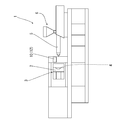
- an injection molding machine 1 as a molding machine in the present embodiment has a structure that is almost the same as a commonly used one, and forms an article by mechanical operation. And a mold clamping unit 3 that opens and closes the mold 2 and a molding mechanism 6 that constitutes an injection unit 5 that heats and melts the resin material and injects the resin material into the cavity 4 of the mold 2.
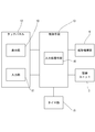
- the injection molding machine 1 includes a touch panel 12 in which a display unit 10 serving as an output interface for a user and an input unit 11 serving as an input interface for receiving input from the user are used, and will be described later.
- the control unit 13 includes a control unit 13 that performs overall control of the injection molding machine 1 such as the mold clamping unit 3 and the molding mechanism unit 6.
- the control unit 13 includes an input unit that is input by operating the touch panel 12. 11 is provided with an input processing means 14 for discriminating a signal from the timer 11, a timer unit 15 for measuring display times of various screens displayed on the display unit 10, and the like.
- the control unit 13 displays an operation setting screen 20 for setting various operations of the injection molding machine 1 on the display unit 10.
- the operation setting screen 20 is displayed for a predetermined time of 5 minutes, and when another 5 minutes have passed, the operation setting screen 20 is an operation process that represents the operation status of the injection molding machine 1 by the control means 13. The screen is switched to the screen 21.
- the control means 13 changes the setting to the standby mode for power saving after the lapse of 5 minutes, thereby The screen of the display unit 10 is turned off, and the screen becomes a non-display screen 22 on which no graphic or character is displayed.
- the operation setting screen 20 that is the first screen is displayed on the display unit 10 for 5 minutes, which is a predetermined time, and the operation setting screen 20 is displayed after 5 minutes, which is the predetermined time.
- the operation process screen 21 that is the second screen is switched to be displayed, and the switched operation process screen 21 is changed to the non-display screen 22 in the standby mode that is the third screen after the lapse of a predetermined time of 5 minutes.
- the non-display screen 22 is switched to the frequently used operation setting screen 20 and is displayed.
- the non-display screen 22 on which no graphic or character is displayed in the standby mode is touched, the operation process screen 21 that is not frequently used is not restored and displayed, but the operation setting that is frequently used is set. Since the screen 20 can be automatically displayed on the display unit 10, it is possible to automatically switch and display the operation setting screen 20 suitable for the user's purpose. Therefore, complicated operations can be eliminated and convenience can be improved.
- the screen displayed when the touch operation is performed is the operation setting screen 20.
- the “selection item screen” is set so that the user can select and display a desired selection item, it can be selected and set on the setting screen 25 shown in FIG. 6, as shown in FIG. By putting a check mark in the rectangular column, the checked item and the corresponding numerical value are displayed on the screen as the selection item screen 20a.
Landscapes
- Engineering & Computer Science (AREA)
- Manufacturing & Machinery (AREA)
- Mechanical Engineering (AREA)
- Injection Moulding Of Plastics Or The Like (AREA)
- User Interface Of Digital Computer (AREA)
- Controls And Circuits For Display Device (AREA)
Abstract
L'objet de la présente invention est de permettre à un affichage d'être automatiquement commuté vers un écran présentant une haute fréquence d'utilisation et répond aux exigences d'un utilisateur. Un écran de réglage de fonctionnement (20) est affiché sur une unité d'affichage (10) pendant cinq minutes, ce qui est une durée prédéterminée, et, une fois les cinq minutes écoulées, l'affichage de l'écran de réglage de fonctionnement (20) est commuté vers l'affichage d'un écran de procédé de fonctionnement (21), et l'écran de procédé de fonctionnement (21) affiché par les transitions de commutation vers un écran d'affichage de flan dans un mode de veille au bout de cinq minutes, ce qui est une durée prédéterminée, est passé. Dans l'état où l'écran d'affichage de flan (22) est affiché, lorsqu'une touche est actionnée sur l'écran, l'affichage est commuté de l'écran d'affichage de flan (22) à l'écran de réglage de fonctionnement (20) qui dispose d'une fréquence d'utilisation élevée. En affichant automatiquement l'écran de réglage de fonctionnement (20) ayant une fréquence d'utilisation élevée sur l'unité d'affichage (10), il est possible d'améliorer le caractère pratique.
Priority Applications (1)
| Application Number | Priority Date | Filing Date | Title |
|---|---|---|---|
| CN201280019982.8A CN103492152B (zh) | 2011-04-26 | 2012-04-17 | 成形机及成形机的画面显示切换控制方法 |
Applications Claiming Priority (2)
| Application Number | Priority Date | Filing Date | Title |
|---|---|---|---|
| JP2011-097817 | 2011-04-26 | ||
| JP2011097817A JP5782288B2 (ja) | 2011-04-26 | 2011-04-26 | 成形機の画面表示切換制御方法 |
Publications (1)
| Publication Number | Publication Date |
|---|---|
| WO2012147563A1 true WO2012147563A1 (fr) | 2012-11-01 |
Family
ID=47072085
Family Applications (1)
| Application Number | Title | Priority Date | Filing Date |
|---|---|---|---|
| PCT/JP2012/060341 Ceased WO2012147563A1 (fr) | 2011-04-26 | 2012-04-17 | Machine à mouler et procédé de commande de commutation d'affichage d'écran pour machine à mouler |
Country Status (3)
| Country | Link |
|---|---|
| JP (1) | JP5782288B2 (fr) |
| CN (1) | CN103492152B (fr) |
| WO (1) | WO2012147563A1 (fr) |
Cited By (1)
| Publication number | Priority date | Publication date | Assignee | Title |
|---|---|---|---|---|
| WO2017146007A1 (fr) * | 2016-02-22 | 2017-08-31 | 東洋機械金属株式会社 | Dispositif d'actionnement d'affichage et machine de moulage |
Families Citing this family (1)
| Publication number | Priority date | Publication date | Assignee | Title |
|---|---|---|---|---|
| JP7852206B2 (ja) * | 2020-03-31 | 2026-04-28 | 住友重機械工業株式会社 | 射出成形機 |
Citations (3)
| Publication number | Priority date | Publication date | Assignee | Title |
|---|---|---|---|---|
| JPS63111028A (ja) * | 1986-10-29 | 1988-05-16 | Nissei Plastics Ind Co | 射出成形機の表示装置 |
| JPH04312827A (ja) * | 1991-04-11 | 1992-11-04 | Toyo Mach & Metal Co Ltd | 射出成形機の表示装置 |
| JP2003181899A (ja) * | 2001-12-19 | 2003-07-02 | Toyo Mach & Metal Co Ltd | 成形機 |
Family Cites Families (9)
| Publication number | Priority date | Publication date | Assignee | Title |
|---|---|---|---|---|
| US5470218A (en) * | 1993-07-07 | 1995-11-28 | Wheaton Inc. | Graphical interface driven injection blow molding apparatus |
| JP4138221B2 (ja) * | 2000-09-14 | 2008-08-27 | 日精樹脂工業株式会社 | 射出成形機の制御装置 |
| JP4648127B2 (ja) * | 2005-08-11 | 2011-03-09 | 東洋機械金属株式会社 | メッセージ表示機能を備えた成形機 |
| JP2008179007A (ja) * | 2007-01-23 | 2008-08-07 | Toyo Mach & Metal Co Ltd | 射出成形機 |
| JP5536324B2 (ja) * | 2008-10-30 | 2014-07-02 | 住友重機械工業株式会社 | 設定確認画面、射出成形機及び設定確認画面の表示方法 |
| JP5184421B2 (ja) * | 2009-03-31 | 2013-04-17 | 住友重機械工業株式会社 | 補機操作制御装置及び補機操作制御方法 |
| CN101934578B (zh) * | 2009-06-29 | 2015-07-15 | 鸿富锦精密工业(深圳)有限公司 | 统一各型注塑成型机操作界面的方法及注塑成型系统 |
| JP2011066850A (ja) * | 2009-09-18 | 2011-03-31 | Fujitsu Toshiba Mobile Communications Ltd | 情報通信端末 |
| JP2011005870A (ja) * | 2010-09-01 | 2011-01-13 | Toshiba Mach Co Ltd | 射出成形機の制御装置 |
-
2011
- 2011-04-26 JP JP2011097817A patent/JP5782288B2/ja active Active
-
2012
- 2012-04-17 CN CN201280019982.8A patent/CN103492152B/zh not_active Expired - Fee Related
- 2012-04-17 WO PCT/JP2012/060341 patent/WO2012147563A1/fr not_active Ceased
Patent Citations (3)
| Publication number | Priority date | Publication date | Assignee | Title |
|---|---|---|---|---|
| JPS63111028A (ja) * | 1986-10-29 | 1988-05-16 | Nissei Plastics Ind Co | 射出成形機の表示装置 |
| JPH04312827A (ja) * | 1991-04-11 | 1992-11-04 | Toyo Mach & Metal Co Ltd | 射出成形機の表示装置 |
| JP2003181899A (ja) * | 2001-12-19 | 2003-07-02 | Toyo Mach & Metal Co Ltd | 成形機 |
Cited By (2)
| Publication number | Priority date | Publication date | Assignee | Title |
|---|---|---|---|---|
| WO2017146007A1 (fr) * | 2016-02-22 | 2017-08-31 | 東洋機械金属株式会社 | Dispositif d'actionnement d'affichage et machine de moulage |
| JP2017148949A (ja) * | 2016-02-22 | 2017-08-31 | 東洋機械金属株式会社 | 表示操作装置および成形機 |
Also Published As
| Publication number | Publication date |
|---|---|
| JP5782288B2 (ja) | 2015-09-24 |
| CN103492152A (zh) | 2014-01-01 |
| JP2012228805A (ja) | 2012-11-22 |
| CN103492152B (zh) | 2016-06-08 |
Similar Documents
| Publication | Publication Date | Title |
|---|---|---|
| JP5421973B2 (ja) | 生産機械の表示装置 | |
| JP2009193423A5 (fr) | ||
| US9632584B2 (en) | On-demand user control | |
| JP2009163345A5 (fr) | ||
| JP6287412B2 (ja) | 図形描画装置、図形描画方法およびプログラム | |
| JP2010066227A5 (ja) | 情報処理装置、情報処理方法および情報処理プログラム | |
| JP2005327000A5 (fr) | ||
| CN104723882B (zh) | 仪表显示方法 | |
| JP5782288B2 (ja) | 成形機の画面表示切換制御方法 | |
| TWI544446B (zh) | Electronic books and computer programs | |
| JP2014237290A (ja) | 射出成形機および射出成形機の制御方法 | |
| CN101075163A (zh) | 利用转轮输入字符的手持装置 | |
| JP6542838B2 (ja) | 産業機械システムおよび産業機械システムの制御方法 | |
| JP2001145947A (ja) | 射出成形機の表示装置 | |
| JP2004148521A (ja) | 射出成形機の表示装置 | |
| JP2004082649A (ja) | 射出成形機の表示装置 | |
| JP2003266498A5 (fr) | ||
| JP4648127B2 (ja) | メッセージ表示機能を備えた成形機 | |
| KR101326910B1 (ko) | 사출성형기 및 그의 시퀀스 제어 방법 | |
| JP2004226078A (ja) | クロノグラフ時計 | |
| JPH03103912A (ja) | タッチパネル入力装置 | |
| JP2002052589A (ja) | 射出成形機の制御方法 | |
| JP2007021827A (ja) | 制御装置のメッセージ表示方法及び射出成形機のメッセージ表示方法 | |
| JP2538661B2 (ja) | プログラマブル操作制御装置 | |
| JP2595045B2 (ja) | タッチパネル入力装置 |
Legal Events
| Date | Code | Title | Description |
|---|---|---|---|
| 121 | Ep: the epo has been informed by wipo that ep was designated in this application |
Ref document number: 12777576 Country of ref document: EP Kind code of ref document: A1 |
|
| NENP | Non-entry into the national phase |
Ref country code: DE |
|
| 122 | Ep: pct application non-entry in european phase |
Ref document number: 12777576 Country of ref document: EP Kind code of ref document: A1 |