WO2012147630A1 - Dispositif d'imagerie et procédé de génération d'image - Google Patents
Dispositif d'imagerie et procédé de génération d'image Download PDFInfo
- Publication number
- WO2012147630A1 WO2012147630A1 PCT/JP2012/060657 JP2012060657W WO2012147630A1 WO 2012147630 A1 WO2012147630 A1 WO 2012147630A1 JP 2012060657 W JP2012060657 W JP 2012060657W WO 2012147630 A1 WO2012147630 A1 WO 2012147630A1
- Authority
- WO
- WIPO (PCT)
- Prior art keywords
- image
- addition
- pixel value
- unit
- added
- Prior art date
- Legal status (The legal status is an assumption and is not a legal conclusion. Google has not performed a legal analysis and makes no representation as to the accuracy of the status listed.)
- Ceased
Links
Images




Classifications
-
- G—PHYSICS
- G06—COMPUTING OR CALCULATING; COUNTING
- G06T—IMAGE DATA PROCESSING OR GENERATION, IN GENERAL
- G06T3/00—Geometric image transformations in the plane of the image
- G06T3/40—Scaling of whole images or parts thereof, e.g. expanding or contracting
- G06T3/4053—Scaling of whole images or parts thereof, e.g. expanding or contracting based on super-resolution, i.e. the output image resolution being higher than the sensor resolution
-
- H—ELECTRICITY
- H04—ELECTRIC COMMUNICATION TECHNIQUE
- H04N—PICTORIAL COMMUNICATION, e.g. TELEVISION
- H04N23/00—Cameras or camera modules comprising electronic image sensors; Control thereof
- H04N23/60—Control of cameras or camera modules
-
- H—ELECTRICITY
- H04—ELECTRIC COMMUNICATION TECHNIQUE
- H04N—PICTORIAL COMMUNICATION, e.g. TELEVISION
- H04N19/00—Methods or arrangements for coding, decoding, compressing or decompressing digital video signals
- H04N19/50—Methods or arrangements for coding, decoding, compressing or decompressing digital video signals using predictive coding
-
- H—ELECTRICITY
- H04—ELECTRIC COMMUNICATION TECHNIQUE
- H04N—PICTORIAL COMMUNICATION, e.g. TELEVISION
- H04N23/00—Cameras or camera modules comprising electronic image sensors; Control thereof
- H04N23/80—Camera processing pipelines; Components thereof
- H04N23/84—Camera processing pipelines; Components thereof for processing colour signals
- H04N23/843—Demosaicing, e.g. interpolating colour pixel values
-
- H—ELECTRICITY
- H04—ELECTRIC COMMUNICATION TECHNIQUE
- H04N—PICTORIAL COMMUNICATION, e.g. TELEVISION
- H04N23/00—Cameras or camera modules comprising electronic image sensors; Control thereof
- H04N23/95—Computational photography systems, e.g. light-field imaging systems
- H04N23/951—Computational photography systems, e.g. light-field imaging systems by using two or more images to influence resolution, frame rate or aspect ratio
-
- H—ELECTRICITY
- H04—ELECTRIC COMMUNICATION TECHNIQUE
- H04N—PICTORIAL COMMUNICATION, e.g. TELEVISION
- H04N25/00—Circuitry of solid-state image sensors [SSIS]; Control thereof
- H04N25/10—Circuitry of solid-state image sensors [SSIS]; Control thereof for transforming different wavelengths into image signals
- H04N25/11—Arrangement of colour filter arrays [CFA]; Filter mosaics
- H04N25/13—Arrangement of colour filter arrays [CFA]; Filter mosaics characterised by the spectral characteristics of the filter elements
- H04N25/134—Arrangement of colour filter arrays [CFA]; Filter mosaics characterised by the spectral characteristics of the filter elements based on three different wavelength filter elements
Definitions
- the present invention relates to an imaging device, an image generation method, and the like.
- Some modern digital cameras and video cameras can be used by switching between still image shooting mode and movie shooting mode. For example, there is one that can shoot a still image with a higher resolution than a moving image by a user operating a button during moving image shooting.
- the method of switching between the still image shooting mode and the moving image shooting mode has a problem that when a user notices a photo opportunity, a decisive moment is often already missed.
- Patent Documents 1 and 2 disclose a technique for synthesizing a high-resolution image from a low-resolution image acquired by pixel shift.
- this method requires imaging by pixel shift, which complicates the camera configuration.
- an imaging device an image generation method, and the like that can acquire a high-resolution image from a low-resolution moving image with simple processing.
- an image acquisition unit that acquires a captured image
- an addition unit that is a unit for acquiring an added pixel value is set for each of a plurality of pixels of the captured image, and a pixel value included in the addition unit is set.
- An addition image generation unit that obtains the addition pixel value by weighted addition, obtains an addition image based on the obtained addition pixel value, a compression processing unit that compresses the addition image, and a decompression that decompresses the compressed addition image A processing unit; an estimation calculation unit that estimates a pixel value of the captured image based on the expanded added image; and an image output unit that outputs a high-resolution image based on the pixel value estimated by the estimation calculation unit;
- the addition image generation unit sequentially shifts the addition unit by pixels, and acquires the first to n ⁇ 1 addition images among the first to nth addition images as the addition image.
- the compression processing unit The kth addition image (k is a natural number of n ⁇ 1 or less (including its value)) and the mth addition image (m is n ⁇ 1 or less other than k) A natural number) difference (including a value) is obtained as an m-th difference image, the k-th addition image and the m-th difference image are compressed, and the decompression processing unit compresses the compressed k-th addition
- the image and the m-th difference image are expanded to obtain the first to (n ⁇ 1) -th added images, and the estimation calculation unit is configured to generate the n-th added image based on the first to (n ⁇ 1) -th added images.
- the present invention relates to an imaging apparatus that obtains an added image by interpolation and estimates a pixel value of the captured image based on the obtained nth added image and the first to (n-1) th added images.
- the addition unit is sequentially pixel-shifted to obtain first to (n ⁇ 1) -th addition images, and the difference between the k-th addition image and the m-th addition image is the m-th difference. Obtained as an image, the kth added image and the mth difference image are compressed. The compressed kth addition image and mth difference image are expanded to obtain first to (n-1) th addition images, and the nth addition is performed based on the first to (n-1) th addition images. An image is obtained by interpolation, and a pixel value of the captured image is estimated based on the first to nth added images.
- the addition image generation unit sequentially sets the addition unit horizontally by one pixel at a time to set the first to n ⁇ 1th positions, and the first to nth positions.
- the first to (n-1) -th added images are acquired at the -1 position, and the addition unit at the n-th position shifts the addition unit at the (n-1) -th position horizontally or vertically by one pixel.
- the addition unit of the mth position and the (m + 1) th position among the first to nth positions may include a common pixel.
- the compression processing unit obtains a difference value between the addition pixel value at the kth position and the addition pixel value at the mth position as a pixel value of the mth difference image. You may have an image generation part.
- the pixel value of the mth difference image can be obtained from the difference value between the pixel value of the kth addition image and the pixel value of the mth addition image.
- the compression processing unit may reversibly compress the m-th difference image by entropy coding.
- the difference image is a difference between the addition image and the addition image
- the entropy of the pixel value can be made smaller than that of the captured image. Therefore, the difference image can be compressed at a high compression rate by entropy encoding.
- the image acquisition unit acquires an image in which pixels of a plurality of colors are arranged as the captured image
- the addition image generation unit has first to n ⁇ 1th color arrangements.
- the first to n ⁇ 1th added pixel values are acquired by setting the addition unit having the above, and the estimation calculation unit obtains the nth added pixel value corresponding to the nth color array by interpolation,
- a first estimation unit configured to estimate a first estimated pixel value based on the nth added pixel value and the acquired first to n ⁇ 1th added pixel values; 1 of the first to n ⁇ 1th summed pixel values, the sth summed pixel value (corresponding to the weighting and color correspondence in the weighted summation is the same as that of the nth color array).
- the nth added pixel value may be interpolated based on s is a natural number of n ⁇ 1 or less (including its value).
- the nth added image can be obtained based on the sth added image having the same correspondence between the weight and the color as the nth added image.
- the color information held by the captured image can be restored with high accuracy.
- the estimation calculation unit obtains the sth and nth addition pixel values by interpolation, the obtained sth and nth addition pixel values, and the obtained first to nth addition pixel values.
- a second estimation unit for estimating a second estimated pixel value based on the s ⁇ 1, s + 1 to n ⁇ 1th added pixel values; and a final estimation based on the first and second estimated pixel values.
- a second synthesizing unit that synthesizes estimated pixel values, wherein the second estimating unit determines the sth and nth added pixel values as the first to s ⁇ 1th, s + 1th to nth It may be obtained by interpolation based on the added pixel value of ⁇ 1 without depending on the color arrangement.
- the first estimation unit when the captured image is an RGB Bayer array image, performs a demosaicing process on the first estimated pixel value of the RGB Bayer array.
- the first RGB pixel value in each pixel is obtained
- the second estimation unit performs a demosaicing process on the second estimated pixel value in the RGB Bayer array to obtain a second RGB pixel value in each pixel.
- the combining unit obtains a first pixel value corresponding to a color difference value based on the first RGB pixel value, and a second value corresponding to a luminance value based on the second RGB pixel value. May be obtained, and the first and second pixel values may be converted into RGB pixel values to obtain final RGB pixel values.
- the final estimated pixel value can be synthesized based on the first estimated pixel value whose color information has been restored and the second estimated pixel value whose resolution information has been restored. Further, by obtaining a pixel value corresponding to the color difference value, color information can be extracted from the first estimated pixel value, and by obtaining a pixel value corresponding to the luminance value, the resolution is obtained from the second estimated pixel value. Information can be retrieved.
- the estimation calculation unit Is a difference value between the added pixel value of the first position and the added pixel value of the second position, and the added pixel value of the first area excluding the overlapping area from the addition unit of the first position
- a relational expression between the first intermediate pixel value that is and the second intermediate pixel value that is the addition pixel value of the second region excluding the overlap region from the addition unit of the second position, and the difference value The first intermediate pixel value is estimated using the relational expression, and the pixel value of each pixel included in the addition unit is obtained using the estimated first intermediate pixel value. May be.
- the estimation calculation unit may include an intermediate included in the intermediate pixel value pattern when successive intermediate pixel values including the first and second intermediate pixel values are used as an intermediate pixel value pattern.
- a relational expression between pixel values is represented using the addition pixel value
- the intermediate pixel value pattern represented by the relational expression between the intermediate pixel values is compared with the addition pixel value, and similarity is evaluated, Based on the similarity evaluation result, an intermediate pixel value included in the intermediate pixel value pattern may be determined so that the similarity is the highest.
- the intermediate pixel value can be obtained by estimation based on a plurality of added pixel values acquired by pixel shifting while the addition unit is superimposed.
- an addition unit which is a unit for acquiring an added pixel value, is set for each of a plurality of pixels of the captured image, and pixel values included in the added unit are weighted and added.
- the addition pixel value is obtained, an addition image based on the obtained addition pixel value is obtained, the addition image is compressed, the compressed addition image is decompressed, and the imaging is performed based on the decompressed addition image
- the addition unit is sequentially pixel-shifted so that the first to n-th added images
- the first to (n ⁇ 1) -th added images are acquired as the added images, and the k-th added image (k is n ⁇ 1 or less (its value) among the first to n ⁇ 1-th added images).
- Natural number and the m-th added image (m is less than or equal to k) N ⁇ 1 or less (including a natural number thereof) difference is obtained as the mth difference image, the kth added image and the mth difference image are compressed, and the compressed kth
- the added image and the mth difference image are expanded to obtain the first to (n-1) th added images, and the nth added image is interpolated based on the first to (n-1) th added images.
- the present invention relates to an image generation method for obtaining and estimating a pixel value of the captured image based on the obtained nth added image and the first to (n-1) th added images.
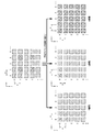
- FIG. 1 is an explanatory diagram of a first data compression method.
- FIG. 2 is an explanatory diagram of the first interpolation method.
- FIG. 3 is an explanatory diagram of a method for generating a color information restoration image.
- FIG. 4 is an explanatory diagram of a method for generating a color information restoration image.
- FIG. 5 is an explanatory diagram of the second interpolation method.
- FIG. 6 is an explanatory diagram of a method for generating a resolution information restoration image.
- FIG. 7 is an explanatory diagram of a method for generating a resolution information restoration image.
- FIG. 8 shows a first configuration example of the imaging apparatus.
- FIG. 9 shows a second configuration example of the imaging apparatus.
- FIG. 10 shows an example of code assignment of fusion image data.
- FIG. 11 is a detailed configuration example of the estimation calculation unit.
- FIG. 12 is a modified configuration example of the estimation calculation unit.
- 13A and 13B are explanatory diagrams of estimated pixel values and intermediate pixel values.
- FIG. 14 is an explanatory diagram of restoration estimation processing.
- FIG. 15 is an explanatory diagram of restoration estimation processing.
- FIG. 16 is an explanatory diagram of restoration estimation processing.
- Digital camera and video camera products have a digital camera that mainly shoots still images with a video shooting function, or a video camera that mainly shoots video with a still image shooting function. There is something. If such a device is used, there is the convenience that a still image and a moving image can be shot with a single device.
- the captured image is pixel-added to obtain a plurality of low resolution images A 1 to A 3 , and the reference image A 2 and the low resolution images A 1 and A 3 are obtained.
- Difference images D 1 and D 3 are obtained, and the difference images D 1 and D 3 are compressed by, for example, entropy coding.
- the difference images D 1 and D 3 since the pixel values are considered to be unevenly distributed near zero, the compression rate can be improved.
- a technique for performing so-called super-resolution processing on a low-resolution image captured by pixel shift is conceivable.
- addition reading is performed while sequentially shifting the position, and a high-definition image is temporarily assumed based on the plurality of position-shifted images. Then, the assumed image is degraded to generate a low resolution image, which is compared with the original low resolution image, and the high definition image is estimated so that the difference is minimized.
- an ML (Maximum-Likelihood) method As this super-resolution processing, an ML (Maximum-Likelihood) method, a MAP (Maximum-A-Posterior) method, a POCS (Projection-Onto-Convex-Set) method, an IBP (Iterative Back-Projection) method, and the like are known.
- ML Maximum-Likelihood
- MAP Maximum-A-Posterior
- POCS Projection-Onto-Convex-Set
- IBP Iterative Back-Projection
- Patent Document 1 For example, in Patent Document 1 described above, low-resolution images that have been pixel-shifted during moving image shooting are sequentially captured in time series, and a plurality of low-resolution images are combined to assume a high-resolution image.
- a technique for performing the above-described super-resolution processing on a high-resolution image and estimating a high-resolution image with high likelihood is disclosed.
- Patent Document 2 a plurality of pixel-shifted low-resolution images are picked up, temporary pixels constituting the high-resolution image to be obtained are set as sub-pixels, and the average value of the sub-pixels is taken as an image.
- a technique for estimating the pixel value of the sub-pixel so as to match the pixel value of the low-resolution image that has been made is disclosed. In this method, initial values of a plurality of sub-pixels are set, pixel values of sub-pixels excluding sub-pixels to be calculated are subtracted from pixel values of the low-resolution image, and pixel values are sequentially obtained for adjacent pixels. Apply.
- the low-resolution images A 1 to A 3 are reproduced from the reference image A 2 and the difference images D 1 and D 3 , and the low-resolution image A 1. based on ⁇ a 3 obtained by interpolating the low resolution image a 4.
- the added pixel values a (1) 00 to a (4) 01 of the low resolution images A 1 to A 4 are shifted by overlapping pixels, and adjacent added pixel values include common pixels.
- the process of estimating a high-resolution image can be simplified by using the added pixel value shifted by the superimposed pixel.
- the frame is, for example, a timing at which an image is captured by an image sensor or a timing at which one captured image is processed in image processing.
- one image in the image data is also referred to as a frame as appropriate.
- a captured image of an RGB Bayer array (hereinafter referred to as “high-definition frame image fx”) is acquired by reading all pixels in a frame fx.
- An addition unit (a pixel group to be added) composed of four pixels is set in the high-definition frame image fx, and the pixel values of the addition unit are weighted and added. At this time, the addition unit is shifted horizontally or vertically while superimposing one pixel, and three pixel addition images A 1 to A 3 are generated.
- the 4-pixel addition value a ij is expressed by the following equation (1), and the addition pixel values constituting the pixel addition images A 1 to A 3 are ⁇ a ij , a (i + 1) j , a (i + 1) (j + 1), respectively. ⁇ .
- the pixel addition image A 4 consists of four pixel sum values a i (j + 1) is not acquired.
- a ij v ij + (1 / r) v (i + 1) j + (1 / r) v i (j + 1) + (1 / r 2 ) v (i + 1) (j + 1) (1)
- V ij is the pixel value of the address (i, j) in the high-definition frame image.
- the generated pixel addition images A 2 as a reference image. Taken after having aligned the addition position of the pixel addition image A 1, A 3 to the addition position of the reference image A 2, the reference image A 2 and two-pixel addition image A 1, A 3 the difference between the respective difference images D 1 and D 3 are generated. Specifically, when the 4-pixel addition values of the pixel addition images A 1 to A 3 are ⁇ a (1) ij , a (2) (i + 1) j , a (3) (i + 1) (j + 1) ⁇ , respectively.
- the 4-pixel addition value ⁇ a A2 ij ⁇ of the reference image A 2 and the 4-pixel addition values ⁇ a D1 ij , a D3 ij ⁇ of the difference images D 1 and D 3 are obtained by the following equation (2).
- the reference image A 2 and the difference images D 1 and D 3 are combined to form fused image data F (M, D 1 to D 4 ).
- a A2 ij a (2) (i + 1) j
- a D1 ij a (1) ij ⁇ a A2 ij
- a D3 ij a (3) (i + 1) (j + 1) -a A2 ij (2)
- the fused image data F (A 2 , D 1 , D 3 ) obtained by fusing the still image and the moving image is generated and recorded, and the recorded F (A 2 , D 1 , It is possible to generate “high-definition still image data” or “moving image data” as appropriate by decompressing D 3 ) in the subsequent stage.
- these reproduced four-pixel addition values ⁇ a (1) ij , a (2) (i + 1) j , a (3) (i + 1) (j + 1) ⁇ are used to perform an interpolation method described later.
- a 4-pixel addition value ⁇ a (4) i (j + 1) ⁇ is obtained.
- the four 4-pixel addition values to which the interpolation values are added are image data composed of 4-pixel addition values obtained by superimposing and shifting one high-definition frame image fx horizontally or vertically one pixel at a time.
- the original high-definition frame image fx is obtained by applying the restoration estimation process described later with reference to FIG.
- Second data compression techniques will now be described for a second data compression techniques to reduce the amount of recorded data of the reference image A 2 mentioned above.
- the added pixel value ⁇ a A2 ij ⁇ is set as a reference pixel added value.
- the remaining added pixel values are represented as difference values ⁇ a D2 (i + 2) j , a D2 i (j + 2) , a D2 (i + 2) (j + 2) ⁇ .
- i and j represent odd pixel addresses.
- the reference pixel addition value ⁇ a A2 ij ⁇ and the difference values ⁇ a D2 (i + 2) j , a D2 i (j + 2) , a D2 (i + 2) (j + 2) ⁇ are used as recording data A 2 ′ for the reference image A 2.
- the difference value is a difference value between adjacent identical weighted addition pixel values, it is considered that the value is unevenly distributed near zero. Therefore, the difference value since the amount of allocation data is reduced, it is possible reduction of the amount of recorded data of the reference image A 2.
- the fused image data is given by F (A 2 ′, D 1 , D 3 ).
- the data of the reference image A 2 is reproduced by the above equation (4).
- the added images A 1 to A 3 are reproduced by the above equation (3).
- the 4-pixel addition values of the 4-pixel addition patterns 1 to 3 are acquired as the pixel values of the addition images A 1 to A 3 .
- 4-pixel sum value of the pixel addition pattern 4 corresponds to the pixel value of the added image A 4, a pixel value obtained by interpolation.
- These four-pixel addition patterns 1 to 4 represent the relationship between the pixel color arrangement and the weighting coefficient.
- Pixel value of the addition image A 4 is determined by interpolation relationship color array and the weighting factor by using the pixel value of the added image A 2 are identical. That is, if Gr and Gb are regarded as the same G color, the weighting coefficients of the 4-pixel addition patterns 2 and 4 are “G pixel:“ 1 ”or“ 1 / r 2 ”” , R pixel: “1 / r”, B Pixel: '1 / r'. These added values have no difference in the relationship between RGB and weighting and can be treated as the same as the added values, so that interpolation processing of the added values is established.
- the pixel value ⁇ a 21 ⁇ of the addition image A 4 is obtained by the interpolation processing shown in the following equation (5) using the detected addition values ⁇ a 10 , a 30 , a 12 , a 32 ⁇ around the diagonal. .
- the other pixel values ⁇ a (4) i (j + 1) ⁇ of the addition image A 4 are similarly obtained from the detected addition values around the diagonal.
- a 21 w 1 ' ⁇ a 10 + w 2 ' ⁇ a 30 + w 3 ' ⁇ a 12 + w 4 ' ⁇ a 32 (5)
- the interpolation coefficients w 1 ′ to w 4 ′ are set in advance so that the interpolation accuracy becomes the highest.
- a conventional method (bilinear, bicubic, etc.) may be used as the interpolation method, or an optimum interpolation coefficient may be set independently.
- the detected 4-pixel addition value used for interpolation is not limited to four adjacent values, and it is needless to say that more pattern values near the periphery may be used.
- a restoration estimation process described later with reference to FIG. 13A or the like is applied to the completed 4-pixel addition value to obtain a first estimated pixel value ⁇ v c ij ⁇ .
- a restored image (frame image for restoring and estimating color information) configured by the estimated pixel value ⁇ v c ij ⁇ is an image of a Bayer array.
- coefficients ⁇ r , ⁇ g , ⁇ b ⁇ and coefficients ⁇ r , ⁇ g , ⁇ b ⁇ for example, generally known when obtaining color difference values when primary color RGB component values are given. Apply known coefficients.
- the pixel values of the added images A 2 and A 4 are obtained using the pixel values of the acquired added images A 1 and A 3 .
- the pixel values of the added images A 1 and A 3 constitute a checkered four-pixel sampling image.
- the 4-pixel addition patterns 1 and 3 are different from the 4-pixel addition patterns 2 and 4 in the relationship between the color and the weighting coefficient.
- the added image A 2 is obtained by interpolation ignoring the relationship between the color and the weighting coefficient. , seeking a 4.
- the pixel value ⁇ a ′ 12 ⁇ of the addition image A 2 is interpolated by the following expression (7) using detection addition values ⁇ a 02 , a 22 , a 11 , a 13 ⁇ adjacent in the vertical and horizontal directions.
- the addition other pixel value of the image A 2 ⁇ a (2) ( i + 1) j ⁇ and addition pixel value of the image A 4 ⁇ a (4) i (j + 1) ⁇
- detection adjacent to the vertical and horizontal It is obtained from the added value.
- a ′ 12 w 1 ⁇ a 02 + w 2 ⁇ a 22 + w 3 ⁇ a 11 + w 4 ⁇ a 13 (7)
- the interpolation coefficients w 1 to w 4 are set in advance so that the interpolation accuracy becomes the highest.
- a conventional method (bilinear, bicubic, etc.) may be used as the interpolation method, or an optimum interpolation coefficient may be set independently.
- the detected 4-pixel addition value used for interpolation is not limited to four adjacent values, and it is needless to say that more pattern values near the periphery may be used.
- the pixel value ⁇ a ′ 12 ⁇ obtained by the interpolation is different from the pixel value ⁇ a 02 , a 22 , a 11 , a 13 ⁇ used for the interpolation in terms of the color arrangement and weighting of the pixels.
- This is a 4-pixel addition value in which the relationship is ignored.
- the pixel value ⁇ a ′ 12 ⁇ obtained by the interpolation is similar to the pixel value ⁇ a 02 , a 22 ⁇ or ⁇ a 11 , a 13 ⁇ used for the interpolation. It just considers the relationship between color scheme and weighting.
- FIG. 6 a restoration estimation process described later with reference to FIG. 13A or the like is applied to a complete 4-pixel addition value to obtain an estimated pixel value ⁇ v r ij ⁇ .
- a restored image (a frame image for restoring and estimating the resolution information) composed of the estimated pixel value ⁇ v r ij ⁇ has a high resolution, but the original image including the color is not restored. Absent.
- the relationship between the color component generated by the restoration process and the pixel value ⁇ v r ij ⁇ will be described by taking as an example the case where the color arrangement is the 4-pixel addition pattern 3 as in the pixel value ⁇ a ′ 12 ⁇ described above.
- the restored pixel values ⁇ v r 12, v r 22 , v r 13, v r 23 ⁇ a single processing unit.
- This processing unit corresponds to the addition unit of the interpolation pixel value ⁇ a ′ 12 ⁇ .
- the colors (R, Gr, Gb, B) corresponding to each pixel are indicated with parentheses so that the color scheme can be clearly identified.
- v r 22 v r 22 (R)
- v r 12 v r 12 (Gr)
- v r 23 v r 23 (Gb)
- v r 13 v r 13 (B)
- v r 22 (R) ⁇ ⁇ r 22 + ⁇ ⁇ g 22 + ⁇ ⁇ b 22
- v r 12 (Gr) ⁇ ⁇ r 12 + ⁇ ⁇ g 12 + ⁇ ⁇ b 12
- v r 23 (Gb) ⁇ ⁇ r 23 + ⁇ ⁇ g 23 + ⁇ ⁇ b 23
- v r 13 (B) ⁇ ⁇ r 13 + ⁇ ⁇ g 13 + ⁇ ⁇ b 13 (9)
- the coefficients ⁇ , ⁇ , ⁇ , and ⁇ are coefficients that are uniquely determined by the number of pixels added in the weighted addition of pixels and the weighting coefficient.
- a three-plate primary color image is generated from the estimated pixel value ⁇ v r ij ⁇ .
- the pixel value v r 22 (R) can be regarded as having an R color component as a main component.
- the pixel values v r 12 (Gr), v r 23 (Gb), and v r 13 (B) can be regarded as having Gr color components, Gb color components, and B color components as main components, respectively. .
- the restored image is approximately Bayer as v ij (R) ⁇ R color component, v ij (Gr) ⁇ Gr color component, v ij (Gb) ⁇ Gb color component, and v ij (B) ⁇ B color component. It can be regarded as an array image.
- the primary color components (r r ij , g r ij , b r ij ) of the resolution information restored image and the primary color components (r c ij , g c ij , b) of the color information restored image Let c ij ) be approximately equal.
- the resolution reflected value ⁇ Y ij ⁇ shown in the above equation (10) and the color difference values ⁇ Cb ij , Cr ij ⁇ shown in the above equation (6) are expressed by the following equation (12): Arranged in the determinant shown.
- components (r ij , g ij , b ij ) of the pixel v ij of the final restored image F are obtained.
- This final restored image F is an image in which both the resolution information and the color information are restored.
- a high-definition restored estimated image F of the original image can be obtained from the added images A 1 to A 3 obtained by weighted superposition shift addition in the original image of one frame. Unlike the case of using multiple frames, the original image can be restored with only one frame, so it is possible to eliminate the cause of image degradation due to image shift, color shift, etc. even for subjects with large movements, and high-quality high-definition images Can be obtained.
- Imaging Device FIG. 8 shows a configuration example of an imaging device that performs the above-described image data compression and restoration estimation processing.
- the imaging apparatus includes an imaging unit 10 that performs imaging and data compression processing, and an image processing unit 20 that performs restoration processing of a high-definition image.
- the image processing unit 20 may be built in the camera body or may be configured by an external information processing apparatus such as a PC.
- the imaging unit 10 includes a lens 110, an imaging element 120 (imaging sensor), an addition image generation unit 130 (superimposition shift weighted addition image generation unit), a compression processing unit 140, and a compressed data recording unit 150 (fusion compression data). Recording section).
- the lens 110 forms an image of the subject 100.
- the image sensor 120 captures the formed subject image.
- An analog signal obtained by imaging is converted into a digital signal by an A / D converter (not shown).
- the addition image generation unit 130 adds the pixel values of the captured image while shifting the pixels, and generates pixel addition images A 1 to A 3 from the captured image.
- the compression processing unit 140 generates difference images D 1 and D 3 from the pixel addition images A 1 to A 3 and performs a process of compressing the reference image A 2 and the difference images D 1 and D 3 .
- the compression processing unit 140 includes a difference image generation unit 141, an entropy encoding unit 143, and a data compression unit 144.
- the difference image generation unit 141 generates difference images D 1 and D 3 from the pixel addition images A 1 to A 3 .
- the entropy encoding unit 143 compresses the difference images D 1 and D 3 by lossless compression of entropy encoding (for example, Huffman code, LZH, etc.).
- Data compression unit 144 for example, compressing the reference image A 2 by lossy compression such as M-JPEG and JPEG-XR.
- the compressed data recording unit 150 records the compressed image data.
- the compressed data recording unit 150 includes a difference data recording unit 151 that records the compressed difference images D 1 and D 3 and a reference image data recording unit 157 that records the compressed reference image A 2 .
- the image processing unit 20 includes an expansion processing unit 205, an estimation calculation unit 230 (high-definition image restoration estimation unit), a high-definition still image generation unit 240, a high-definition moving image generation unit 250, a standard moving image generation unit 260, an image output unit 290, An image selection unit 295 is included.
- the decompression processing unit 205 decompresses the compressed data and reproduces the added images A 1 to A 3 .
- the expansion processing unit 205 includes a compressed data expansion unit 200 and an addition image reproduction unit 210 (weighted addition image reproduction unit).
- the compressed data decompression unit 200 performs a process of decompressing the compressed reference image A 2 and the difference images D 1 and D 3 .
- the added image reproduction unit 210 performs a process of reproducing the added images A 1 to A 3 from the reference image A 2 and the difference images D 1 and D 3 .
- the estimation calculation unit 230 obtains the color information restoration image F c and the resolution information restoration image F r based on the added images A 1 to A 3 and obtains the restoration image F from these images.
- the restored image is an RGB Bayer array image.
- the high-definition still image generation unit 240 performs image processing such as gradation correction processing on the restored image F to generate a high-definition still image. At this time, a still image at the timing selected by the image selection unit 295 is generated. The timing is selected according to the user's instruction, and the user selects the timing by looking at the output moving image of the image output unit 290, for example.
- the high-definition moving image generation unit 250 performs image processing such as gradation correction processing on the moving image based on the restored image F to generate a high-definition moving image.
- the standard moving image generation unit 260 downsamples the high-definition moving image, and generates, for example, a moving image having the number of high-definition pixels as the standard moving image.
- the image output unit 290 outputs a high-definition still image, a high-definition moving image, and a standard moving image to, for example, a display device or a printer.
- FIG. 9 shows a modified configuration example of the imaging apparatus when the fusion image data F (A 2 , D 1 , D 3 ) is irreversibly compressed.
- the imaging device includes an imaging unit 10 and an image processing unit 20.
- the same components as those described above with reference to FIG. 8 are denoted by the same reference numerals, and description thereof will be omitted as appropriate.
- the imaging unit 10 includes a lens 110, an imaging element 120, an addition image generation unit 130, a difference image generation unit 141, a data storage unit 149, a compressed data recording unit 150, and a data compression unit 156.
- the components of the image processing unit 20 are the same as those of the image processing unit 20 in FIG.
- the data storage unit 149 stores the fusion image data F (A 2 , D 1 , D 3 ).
- the fused image data F (A 2 , D 1 , D 3 ) is image data composed of the reference image A 2 from the addition image generation unit 130 and the difference images D 1 and D 3 from the difference image generation unit 141. is there.
- the data compression unit 156 compresses the fused image data F (A 2 , D 1 , D 3 ) by irreversible compression such as M-JPEG or JPEG-XR.
- the compressed data recording unit 150 records the compressed fused image data F (A 2 , D 1 , D 3 ).
- FIG. 10 shows a code assignment example of the above-described fusion image data F (A 2 , D 1 , D 3 ).
- the pixel value of the coordinates (i, j) of the fused image data F (A 2 , D 1 , D 3 ) is set to 1 unit for 3 frames, and 48 bits are assigned to that unit. Specifically, 8 bits are allocated to the pixel values a (2) k to a (2) k + 2 of the reference image A 2 in the kth to k + 2th frames (k is a natural number). Four bits are assigned to the pixel values a D1 k to a D1 k + 2 and a D3 k to a D3 k + 2 of the difference images D 1 and D 3 of the kth to k + 2th frames, respectively.
- a (2) k to a (2) k + 2 and a D1 k to a D1 k + 2 constitute 12-bit data, respectively, and a D3 k to a D3 k + 2 constitute 12-bit data.
- the number of pixels of the captured image (original image) is N pixels, and the pixel value data is 12 bits.
- FIG. 11 shows a detailed configuration example of the above-described estimation calculation unit 230.
- the estimation calculation unit 230 includes a color information estimation unit 231 (first estimation unit), a resolution information estimation unit 232 (second estimation unit), and a synthesis unit 233.
- the color information estimation unit 231 obtains the addition image A 4 from the addition image A 2 by interpolation using the first interpolation method described above, and the color information restoration image F from the obtained addition image A 4 and the addition images A 1 to A 3. c is generated.
- the resolution information estimation unit 232 obtains the added images A 2 and A 4 by interpolation from the added images A 1 and A 3 by the second interpolation method described above, and obtains the obtained added images A 2 and A 4 and the added image A. 1 , a resolution information restoration image F r is generated from A 3 .
- the synthesis unit 233 obtains the RGB pixel values (r ij , g ij , b ij ) of the final restored image from the color information restored image F c and the resolution information restored image F r by the above-described synthesis method.
- FIG. 12 shows a modified configuration example of the estimation calculation unit in this case.
- the estimation calculation unit 230 includes an interpolation processing unit 235 and a restoration estimation processing unit 236.
- Interpolation processing unit 235 the first interpolation method described above, obtained by interpolation of the addition image A 4 from the addition image A 2.
- the restoration estimation processing unit 236 generates a color information restoration image F c from the obtained addition image A 4 and the addition images A 1 to A 3 and outputs F c as a final restoration image.
- the image processed image may be output as a final reconstructed image of which was performed on the color information restored image F c.
- a high-speed and low-load estimation calculation unit can be configured.
- the imaging device includes an image acquisition unit (for example, the imaging device 120), the addition image generation unit 130, the compression processing unit 140, the expansion processing unit 205, and the estimation.
- a calculation unit 230 and an image output unit 290 are included.
- the image acquisition unit acquires the captured image fx (high-definition frame image).
- the addition image generation unit 130 sets an addition unit, which is a unit for acquiring an addition pixel value (for example, a (1) ij ), for each of a plurality of pixels (for example, every four pixels) of the captured image fx, and is included in the addition unit.
- the pixel values to be added are weighted and added (the above equation (1)) to obtain the added pixel values, and the added images A 1 to A 3 based on the obtained added pixel values are obtained.
- the compression processing unit 140 compresses the added images A 1 to A 3 .
- the decompression processing unit 205 decompresses the compressed added images A 1 to A 3 .
- the estimation calculation unit 230 estimates the pixel value v ij of the captured image fx based on the expanded added images A 1 to A 3 .
- the image output unit 290 outputs a high resolution image based on the estimated pixel value v ij .
- the addition image generation unit 130 sequentially shifts the addition unit by a pixel, and the first to fourth of the first to fourth (first to nth in a broad sense) addition images A 1 to A 4 .
- 3 addition images A 1 to A 3 are acquired.
- the compression processing unit 140 calculates a difference between the k-th added image A k (reference image) and the m-th added image A m (k, m are natural numbers less than or equal to 3 (including their values), m ⁇ k). It calculates
- the expansion processing unit 205 expands the compressed addition image A k and the difference image D m to obtain addition images A 1 to A 3 .
- the estimation calculation unit 230 obtains a fourth (nth in a broad sense) addition image A 4 by interpolation based on the addition images A 1 to A 3, and determines the obtained addition image A 4 and addition images A 1 to A 3 . Based on this, the pixel value v ij of the captured image fx is estimated.
- the captured image fx can be efficiently compressed. That is, the total number of pixels of the three added images A 1 to A 3 is 3/4 of the number of pixels of the captured image fx, and the number of pixels is reduced.
- the pixel values of the difference image D m as described above would be considered to be localized near the zero, the entropy of the difference image D m is smaller than the captured image fx. Therefore, the compression rate can be improved by entropy encoding the difference image Dm, for example.
- the captured image fx can be restored from the high-compression-rate image data to extract a high-definition still image at an arbitrary timing. Further, since the addition images A 1 to A 3 are generated from one captured image fx, a restored image with a high temporal resolution with little blurring can be obtained even with moving objects.
- the captured image fx can be reproduced from the compressed data with a simple process. That is, the addition images A 1 to A 3 and the addition image A 4 obtained by interpolation are image data obtained by superposition shift addition, and a restoration estimation process described later can be applied.
- This restoration estimation process can simplify the process of estimating a high-resolution image from a low-resolution image as compared with Patent Documents 1 and 2 described above.
- the first to fourth addition images A 1 to A 4 are images necessary for estimating the pixel value v ij of the captured image fx, and are one-round images among the cyclic images. is there. That is, if (in a broad sense the n + 1) 5 if acquired by weighted addition of added image A 5, its fifth addition image A 5 of becomes the first addition image A 1 and the same image, and later, That is, the same image appears every four images.
- the addition image generation unit 130 sequentially shifts the addition unit one pixel at a time horizontally or vertically (i-axis direction or j-axis direction). Positions (for example, coordinates (0, 0), (1, 0), (1, 1)) are set, and added images A 1 to A 3 are obtained at the first to third positions, respectively.
- the addition unit of the m-th position and the m + 1-th position (for example, (0, 0), (1, 0)) includes a common pixel (v 10 , v 11 ).
- the compression processing unit 140 includes a difference image generation unit 141.
- the difference image generation unit 141 includes the added pixel value a (2) (i + 1) j at the k- th position and the added pixel value (for example, a (1) ij ) at the m-th position.
- the difference value (a D1 ij ) is obtained as the pixel value of the mth difference image Dm.
- the compression processing unit 140 losslessly compresses the mth difference image Dm by entropy coding.
- the image acquisition unit acquires an image (for example, a Bayer array image) in which pixels of a plurality of colors (for example, R, Gr, Gb, and B) are arrayed as the captured image fx.
- the addition image generation unit 130 sets the addition units having the first to third color arrangements (four-pixel addition patterns 1 to 3) and sets the first to third addition pixel values ⁇ a (1) ij , a (2) (i + 1) j , a (3) (i + 1) (j + 1) ⁇ are acquired.
- the estimation calculation unit 230 includes a first estimation unit (color information estimation unit 231). As illustrated in FIG.
- the first estimation unit includes a fourth addition pixel value (for example, a 12 , in a broad sense, ⁇ a (4) i ( ), corresponding to the fourth color arrangement (four-pixel addition pattern 4). j + 1) ⁇ ) is obtained by interpolation. As shown in FIG. 3, the first estimation unit calculates the first estimated pixel value ⁇ v c based on the obtained fourth added pixel value and the obtained first to third added pixel values. ij ⁇ is estimated. As described above with reference to FIG. 2, the first estimation unit has a fourth color arrangement (four-pixel addition pattern 4) in which the correspondence between weighting and color in the weighted addition among the first to third addition pixel values. The fourth addition pixel value is interpolated based on the second (sth in a broad sense) addition pixel value that is the same as.
- a fourth addition pixel value for example, a 12 , in a broad sense, ⁇ a (4) i ( ), corresponding to the fourth color arrangement (four-pixel addition pattern 4).
- the estimation calculation unit 230 includes a second estimation unit (resolution information estimation unit 232) and a synthesis unit 233.
- the second estimation unit obtains the second and fourth addition pixel values ⁇ a (2) (i + 1) j , a (4) i (j + 1) ⁇ by interpolation.
- the second estimation unit calculates the second estimation pixel based on the obtained second and fourth addition pixel values and the obtained first and third addition pixel values. Estimate the value ⁇ v r ij ⁇ .
- the synthesizer 233 synthesizes the final estimated pixel value ⁇ v ij ⁇ based on the first and second estimated pixel values ⁇ v c ij , v r ij ⁇ .
- the second estimation unit obtains the second and fourth addition pixel values by interpolation based on the first and third addition pixel values without depending on the color arrangement.
- the added images A 2 and A 4 can be obtained by interpolation not depending on the color arrangement.
- resolution information for example, the luminance value of each pixel
- the first and third addition pixel values eg, a 11 , a 22 etc.
- the second and fourth addition pixel values eg, a 12 .
- the interpolation can be performed using the close addition pixel values, so that higher resolution can be restored. This interpolation is possible by ignoring the color arrangement and using a closer added pixel value.
- the captured image fx is an RGB Bayer array image.
- the first estimation unit performs demosaicing processing on the first estimated pixel value ⁇ v c ij ⁇ of the RGB Bayer array, and the first RGB pixel value (r c) in each pixel. ij , g c ij , b c ij ).
- the second estimation unit performs (approximately) demosaicing processing on the second estimated pixel value ⁇ v r ij ⁇ of the RGB Bayer array, and performs second RGB in each pixel. Pixel values (r r ij , g r ij , b r ij ) are obtained.
- the synthesizing unit 233 obtains a first pixel value (color difference value ⁇ Cb ij , Cr ij ⁇ ) corresponding to the color difference value based on the first RGB pixel value (the above formula (6)), and the second RGB Based on the pixel value, a second pixel value (resolution reflected value ⁇ Y ij ⁇ ) corresponding to the luminance value is obtained.
- the synthesizer 233 converts the first and second pixel values into RGB pixel values to obtain final RGB pixel values (r ij , g ij , b ij ). Ask.
- the final estimated pixel value can be synthesized based on the first estimated pixel value whose color information has been restored and the second estimated pixel value whose resolution information has been restored. Further, by obtaining a pixel value corresponding to the color difference value from the first estimated pixel value, it is possible to extract color information from the first estimated pixel value. Further, by obtaining a pixel value corresponding to a luminance value from the second estimated pixel value, it is possible to extract resolution information from the second estimated pixel value.
- the estimation processing performed by the above-described estimation calculation unit 230 will be described in detail with reference to FIG.
- the addition pixel values ⁇ a 00 , a 10 , a 11 , a 01 ⁇ will be described as an example (i and j are integers greater than or equal to 0 (including their values)). It is the same. Further, the case where the addition unit is set for every 2 ⁇ 2 pixels will be described as an example, but the present invention is not limited to this, and may be, for example, every 3 ⁇ 3 pixels.
- 13A and 13B are explanatory diagrams of the estimated pixel value and the intermediate pixel value. Summing the pixel values shown in FIG. 13 (A) ⁇ a 00, a 10, a 11, a 01 ⁇ is added pixel value of the added image A 1 ⁇ A 4 described in FIG. 1 ⁇ a (1) 00, a ( 2) Corresponds to 10 , a (3) 11 , a (4) 01 ⁇ . In the estimation process, final estimated pixel values v 00 to v 22 are estimated using this added pixel value.
- the estimated pixel value v ij corresponds to the pixel value of the captured image fx described in FIG.
- intermediate pixel values b 00 to b 21 are estimated from the added pixel values a 00 to a 11 .
- Intermediate pixel value corresponds to 2-pixel sum values, for example, b 00 corresponds to the sum of the pixel values v 00 and v 01.
- Final pixel values v 00 to v 22 are estimated from these intermediate pixel values b 00 to b 21 .
- the intermediate pixel values b 00 to b 20 are estimated based on the added pixel values a 00 and a 10 in the first row in the horizontal direction.
- the added pixel values a 00 and a 10 are expressed by the following expression (13).
- a 00 v 00 + (1/2) v 01 + (1/2) v 10 + (1/4) v 11
- a 10 v 10 + (1/2 ) v 11 + (1/2) v 20 + (1/4) v 21 (13)
- B 00 , b 10 , and b 20 are defined as shown in the following formula (14).
- b 00 v 00 + (1 / r)
- v 01 v 00 + (1/2) v 01
- b 10 v 10 + (1 / r)
- v 11 v 10 + (1/2) v 11
- b 20 v 20 + (1 / r)
- v 21 v 20 + (1/2) v 21 (14)
- intermediate pixel values b 10 and b 20 can be obtained as a function of b 00 as shown in the following equation (17). In this way, a high-definition combination pattern of intermediate pixel values ⁇ b 00 , b 10 , b 20 ⁇ is obtained with b 00 as an unknown.
- b 00 (unknown number)
- b 10 2 (a 00 -b 00 )
- the pattern ⁇ a 00 , a 10 ⁇ of the added pixel value and the pattern ⁇ b 00 , b 10 , b 20 ⁇ of the intermediate pixel value are compared. Then, an unknown number b 00 that minimizes the error E is derived and set as the intermediate pixel value b 00 .
- the addition unit (for example, a 00 ) set to the first position and the second position next to the first position are set.
- the addition unit (for example, a 10 ) is overlapped.
- the estimation calculation unit 230 obtains a difference value ⁇ i 0 between the added pixel values a 00 and a 10 at the first and second positions.
- the first intermediate pixel value b 00 is an addition of the first region (v 00 , v 01 ) obtained by removing the overlapping region (v 10 , v 11 ) from the addition unit a 00. It is a pixel value.
- the second intermediate pixel value b 20 is an addition pixel value of the second region (v 20 , v 21 ) obtained by removing the overlap region (v 10 , v 11 ) from the addition unit a 10 .
- the relational expression between the first and second intermediate pixel values b 00 and b 20 is expressed using the difference value ⁇ i 0 .
- the first and second intermediate pixel values b 00 and b 20 are estimated using the relational expression. Using the estimated first intermediate pixel value b 00 , pixel values (v 00 , v 10 , v 11 , v 01 ) of each pixel included in the addition unit are obtained.
- superimposing means having a region where the addition unit and the addition unit overlap.
- the addition unit a 00 and the addition unit a 10 are two estimated pixels v 10. is to share the v 11.
- the position of the addition unit is the position and coordinates of the addition unit in the captured image, or the position and coordinates of the addition unit on the estimated pixel value data (image data) in the estimation process.
- the next position is a position shifted from the original position by a pixel, and is a position where the position and coordinates do not coincide with the original position.
- continuous intermediate pixel values including the first and second intermediate pixel values are defined as intermediate pixel value patterns ( ⁇ b 00 , b 10 , b 20 ⁇ ).
- the estimation calculation unit 230 represents the relational expression between the intermediate pixel values included in the intermediate pixel value pattern using the added pixel values a 00 and a 10 .
- the similarity is evaluated by comparing the intermediate pixel value pattern represented by the relational expression between the intermediate pixel values and the added pixel value. Based on the similarity evaluation result, the intermediate pixel values b 00 , b 10 , and b 20 included in the intermediate pixel value pattern are determined so that the similarity is the highest.
- the intermediate pixel value can be estimated based on a plurality of added pixel values acquired by pixel shifting while the addition unit is superimposed.
- the intermediate pixel value pattern is a data string (a set of data) of intermediate pixel values in a range used for the estimation process.
- the addition pixel value pattern is a data string of addition pixel values in a range used for the estimation process.
- the estimation calculation unit 230 has an intermediate pixel value pattern ( ⁇ b 00 , b 10 , b 20 ⁇ ) represented by a relational expression between intermediate pixel values. And an evaluation function Ej representing an error between the pixel value (a 00 and a 10 ).
- the intermediate pixel values b 00 , b 10 and b 20 included in the intermediate pixel value pattern are determined so that the value of the evaluation function Ej is minimized.
- the value of the intermediate pixel value can be estimated by expressing the error by the evaluation function and obtaining the intermediate pixel value corresponding to the minimum value of the evaluation function.
- the initial value of the intermediate pixel estimation can be set with a simple process by obtaining the unknown using the least square method. For example, searching for an image portion suitable for initial value setting (Patent Document 2) is unnecessary.
- an addition pixel value (a 00 ) obtained by weighting and adding each pixel value (for example, v 00 , v 10 , v 01 , v 11 ) of the addition unit is used. get. Based on the obtained addition pixel value (a 00 , a 10 ) of the addition unit, the pixel value (v 00 , v 10 , v 01 , v 11 ) of each pixel of the addition unit is estimated.
- each pixel value of the addition unit is weighted and added to obtain an added image, and the pixel value of the high resolution image can be estimated from the obtained added image.
- the reproducibility of the high-frequency component of the subject can be improved. That is, when the pixel values of the addition unit are simply added, a rectangular window function is convoluted for imaging.
- a window function containing more high frequency components than the rectangle is convoluted for imaging. Therefore, it is possible to acquire an added image that includes more high-frequency components of the subject, and to improve the reproducibility of the high-frequency components in the estimated image.
- imaging unit 20 image processing unit, 100 subject, 110 lens, 120 imaging elements, 130 addition image generation unit, 140 compression processing unit, 141 difference image generation unit, 143 entropy encoding unit, 144 data compression unit, 149 data storage unit, 150 compressed data recording unit, 151 differential data recording unit, 156 data compression unit, 157 reference image data recording unit, 200 compressed data decompression unit, 205 expansion processing unit, 210 addition image reproduction unit, 230 estimation calculation unit, 231 color information estimation unit, 232 resolution information estimation unit, 233 synthesis unit, 235 interpolation processing unit, 236 restoration estimation processing unit, 240 high-definition still image generation unit, 250 high-definition video generation unit, 260 standard video generation unit, 290 image output unit, 295 image selector, A 1 to A 4 first to fourth addition images, D 1 and D 3 first and third difference images, Ej evaluation function, F c color information restored image, F r resolution information restored image, a ij addition pixel value, b 00 unknown, b ij intermediate
Landscapes
- Engineering & Computer Science (AREA)
- Multimedia (AREA)
- Signal Processing (AREA)
- Physics & Mathematics (AREA)
- Spectroscopy & Molecular Physics (AREA)
- Theoretical Computer Science (AREA)
- Computing Systems (AREA)
- General Physics & Mathematics (AREA)
- Image Processing (AREA)
- Editing Of Facsimile Originals (AREA)
- Studio Devices (AREA)
- Compression Or Coding Systems Of Tv Signals (AREA)
Abstract
La présente invention se rapporte à un dispositif d'imagerie qui contient une unité d'acquisition d'image, une unité de génération d'image ajoutée, une unité de traitement de compression, une unité de traitement d'agrandissement, une unité de calcul d'estimation et une unité de sortie d'image. L'unité de génération d'image ajoutée acquiert des images ajoutées (A1 à A3) au moyen de l'addition pondérée des valeurs de pixel contenues dans une unité d'addition tout en déplaçant séquentiellement les pixels de l'unité d'addition. L'unité de compression détermine la différence entre l'image ajoutée (A2) et les images ajoutées (A1) et (A3) comme étant les images de différence (D1) et (D3), et compresse les images (A2), (D1) et (D3). L'unité de traitement d'agrandissement détermine les images ajoutées (A1 à A3) par agrandissement des images compressées (A2), (D1) et (D3). L'unité de calcul d'estimation détermine l'image ajoutée (A4) au moyen d'une interpolation sur la base des images ajoutées (A1 à A3) et estime les valeurs de pixel (vij) d'une image capturée (fx) sur la base de l'image ajoutée déterminée (A4) et des images ajoutées (A1 à A3). L'unité de sortie d'image sort une image haute résolution sur la base des valeurs de pixel estimées (vij).
Applications Claiming Priority (2)
| Application Number | Priority Date | Filing Date | Title |
|---|---|---|---|
| JP2011099266A JP2012231378A (ja) | 2011-04-27 | 2011-04-27 | 撮像装置及び画像生成方法 |
| JP2011-099266 | 2011-04-27 |
Publications (1)
| Publication Number | Publication Date |
|---|---|
| WO2012147630A1 true WO2012147630A1 (fr) | 2012-11-01 |
Family
ID=47072150
Family Applications (1)
| Application Number | Title | Priority Date | Filing Date |
|---|---|---|---|
| PCT/JP2012/060657 Ceased WO2012147630A1 (fr) | 2011-04-27 | 2012-04-20 | Dispositif d'imagerie et procédé de génération d'image |
Country Status (2)
| Country | Link |
|---|---|
| JP (1) | JP2012231378A (fr) |
| WO (1) | WO2012147630A1 (fr) |
Cited By (1)
| Publication number | Priority date | Publication date | Assignee | Title |
|---|---|---|---|---|
| US20240046414A1 (en) * | 2021-06-24 | 2024-02-08 | Tcl China Star Optoelectronics Technology Co., Ltd. | Super-resolution image reconstruction method and device |
Families Citing this family (2)
| Publication number | Priority date | Publication date | Assignee | Title |
|---|---|---|---|---|
| JP6135865B2 (ja) * | 2013-12-05 | 2017-05-31 | パナソニックIpマネジメント株式会社 | 撮像システム、撮像装置、および撮像方法 |
| CN116134489B (zh) | 2020-09-01 | 2025-02-07 | Oppo广东移动通信有限公司 | 生成目标图像数据的方法、电子装置,和非暂时性计算机可读介质 |
Citations (3)
| Publication number | Priority date | Publication date | Assignee | Title |
|---|---|---|---|---|
| JP2009124621A (ja) * | 2007-11-19 | 2009-06-04 | Sanyo Electric Co Ltd | 超解像処理装置及び方法並びに撮像装置 |
| JP2009278473A (ja) * | 2008-05-15 | 2009-11-26 | Sanyo Electric Co Ltd | 画像処理装置、それを搭載した撮像装置、および画像再生装置 |
| WO2011090107A1 (fr) * | 2010-01-21 | 2011-07-28 | オリンパス株式会社 | Dispositif de traitement d'image, dispositif de formation d'image, programme, et procédé de traitement d'image |
-
2011
- 2011-04-27 JP JP2011099266A patent/JP2012231378A/ja not_active Withdrawn
-
2012
- 2012-04-20 WO PCT/JP2012/060657 patent/WO2012147630A1/fr not_active Ceased
Patent Citations (3)
| Publication number | Priority date | Publication date | Assignee | Title |
|---|---|---|---|---|
| JP2009124621A (ja) * | 2007-11-19 | 2009-06-04 | Sanyo Electric Co Ltd | 超解像処理装置及び方法並びに撮像装置 |
| JP2009278473A (ja) * | 2008-05-15 | 2009-11-26 | Sanyo Electric Co Ltd | 画像処理装置、それを搭載した撮像装置、および画像再生装置 |
| WO2011090107A1 (fr) * | 2010-01-21 | 2011-07-28 | オリンパス株式会社 | Dispositif de traitement d'image, dispositif de formation d'image, programme, et procédé de traitement d'image |
Cited By (2)
| Publication number | Priority date | Publication date | Assignee | Title |
|---|---|---|---|---|
| US20240046414A1 (en) * | 2021-06-24 | 2024-02-08 | Tcl China Star Optoelectronics Technology Co., Ltd. | Super-resolution image reconstruction method and device |
| US12462338B2 (en) * | 2021-06-24 | 2025-11-04 | Tcl China Star Optoelectronics Technology Co., Ltd. | Super-resolution image reconstruction method and device |
Also Published As
| Publication number | Publication date |
|---|---|
| JP2012231378A (ja) | 2012-11-22 |
Similar Documents
| Publication | Publication Date | Title |
|---|---|---|
| US9094648B2 (en) | Tone mapping for low-light video frame enhancement | |
| JP5306563B2 (ja) | 撮像装置及び画像生成方法 | |
| US9307212B2 (en) | Tone mapping for low-light video frame enhancement | |
| US8749646B2 (en) | Image processing apparatus, imaging apparatus, solid-state imaging device, image processing method and program | |
| JP5341010B2 (ja) | 画像処理装置、撮像装置、プログラム及び画像処理方法 | |
| US20130083220A1 (en) | Image processing device, imaging device, information storage device, and image processing method | |
| JP2009194896A (ja) | 画像処理装置及び方法並びに撮像装置 | |
| WO2012147523A1 (fr) | Dispositif d'imagerie et procédé de génération d'image | |
| WO2004068862A1 (fr) | Procede, systeme et logiciel de creation d'image couleurs haute resolution | |
| WO2011090107A1 (fr) | Dispositif de traitement d'image, dispositif de formation d'image, programme, et procédé de traitement d'image | |
| JP2009037460A (ja) | 画像処理方法、画像処理装置、及びこの画像処理装置を備えた電子機器 | |
| JPH09284798A (ja) | 信号処理装置 | |
| JP5513978B2 (ja) | 撮像装置、集積回路および画像処理方法 | |
| CN101521751A (zh) | 摄像设备 | |
| CN102868890A (zh) | 图像处理设备、成像设备、图像处理方法和程序 | |
| JP5691374B2 (ja) | データ圧縮装置 | |
| JP4810807B2 (ja) | 動画像変換装置、動画像復元装置、および方法、並びにコンピュータ・プログラム | |
| WO2012147630A1 (fr) | Dispositif d'imagerie et procédé de génération d'image | |
| JP4942563B2 (ja) | 画像処理方法、画像処理装置、及びこの画像処理装置を備えた電子機器 | |
| JP2010004396A (ja) | 画像処理装置、画像処理方法及び撮像装置 | |
| JP2013126123A (ja) | 画像処理装置、撮像装置及び画像処理方法 | |
| JP2009273072A (ja) | 高精細画像処理装置、高精細画像処理方法、およびプログラム | |
| JP4339671B2 (ja) | 撮像装置 | |
| JP2012231379A (ja) | 撮像装置及び画像生成方法 | |
| JP2012119852A (ja) | 撮像装置及び撮像方法 |
Legal Events
| Date | Code | Title | Description |
|---|---|---|---|
| 121 | Ep: the epo has been informed by wipo that ep was designated in this application |
Ref document number: 12775927 Country of ref document: EP Kind code of ref document: A1 |
|
| NENP | Non-entry into the national phase |
Ref country code: DE |
|
| 122 | Ep: pct application non-entry in european phase |
Ref document number: 12775927 Country of ref document: EP Kind code of ref document: A1 |