WO2012147647A1 - Accumulateur lithium-ion - Google Patents
Accumulateur lithium-ion Download PDFInfo
- Publication number
- WO2012147647A1 WO2012147647A1 PCT/JP2012/060710 JP2012060710W WO2012147647A1 WO 2012147647 A1 WO2012147647 A1 WO 2012147647A1 JP 2012060710 W JP2012060710 W JP 2012060710W WO 2012147647 A1 WO2012147647 A1 WO 2012147647A1
- Authority
- WO
- WIPO (PCT)
- Prior art keywords
- negative electrode
- ion secondary
- lithium ion
- battery
- active material
- Prior art date
- Legal status (The legal status is an assumption and is not a legal conclusion. Google has not performed a legal analysis and makes no representation as to the accuracy of the status listed.)
- Ceased
Links
Images


Classifications
-
- H—ELECTRICITY
- H01—ELECTRIC ELEMENTS
- H01M—PROCESSES OR MEANS, e.g. BATTERIES, FOR THE DIRECT CONVERSION OF CHEMICAL ENERGY INTO ELECTRICAL ENERGY
- H01M10/00—Secondary cells; Manufacture thereof
- H01M10/05—Accumulators with non-aqueous electrolyte
- H01M10/052—Li-accumulators
- H01M10/0525—Rocking-chair batteries, i.e. batteries with lithium insertion or intercalation in both electrodes; Lithium-ion batteries
-
- H—ELECTRICITY
- H01—ELECTRIC ELEMENTS
- H01M—PROCESSES OR MEANS, e.g. BATTERIES, FOR THE DIRECT CONVERSION OF CHEMICAL ENERGY INTO ELECTRICAL ENERGY
- H01M4/00—Electrodes
- H01M4/02—Electrodes composed of, or comprising, active material
- H01M4/62—Selection of inactive substances as ingredients for active masses, e.g. binders, fillers
- H01M4/624—Electric conductive fillers
- H01M4/625—Carbon or graphite
-
- Y—GENERAL TAGGING OF NEW TECHNOLOGICAL DEVELOPMENTS; GENERAL TAGGING OF CROSS-SECTIONAL TECHNOLOGIES SPANNING OVER SEVERAL SECTIONS OF THE IPC; TECHNICAL SUBJECTS COVERED BY FORMER USPC CROSS-REFERENCE ART COLLECTIONS [XRACs] AND DIGESTS
- Y02—TECHNOLOGIES OR APPLICATIONS FOR MITIGATION OR ADAPTATION AGAINST CLIMATE CHANGE
- Y02E—REDUCTION OF GREENHOUSE GAS [GHG] EMISSIONS, RELATED TO ENERGY GENERATION, TRANSMISSION OR DISTRIBUTION
- Y02E60/00—Enabling technologies; Technologies with a potential or indirect contribution to GHG emissions mitigation
- Y02E60/10—Energy storage using batteries
-
- Y—GENERAL TAGGING OF NEW TECHNOLOGICAL DEVELOPMENTS; GENERAL TAGGING OF CROSS-SECTIONAL TECHNOLOGIES SPANNING OVER SEVERAL SECTIONS OF THE IPC; TECHNICAL SUBJECTS COVERED BY FORMER USPC CROSS-REFERENCE ART COLLECTIONS [XRACs] AND DIGESTS
- Y02—TECHNOLOGIES OR APPLICATIONS FOR MITIGATION OR ADAPTATION AGAINST CLIMATE CHANGE
- Y02P—CLIMATE CHANGE MITIGATION TECHNOLOGIES IN THE PRODUCTION OR PROCESSING OF GOODS
- Y02P70/00—Climate change mitigation technologies in the production process for final industrial or consumer products
- Y02P70/50—Manufacturing or production processes characterised by the final manufactured product
Definitions
- the present invention relates to a lithium ion secondary battery, and more particularly to a lithium ion secondary battery that has a high capacity and a long life by devising a negative electrode active material.
- a lithium ion secondary battery includes a positive electrode in which a positive electrode active material or the like is applied to the surface of the current collector using a binder, and a negative electrode in which a negative electrode active material or the like is applied to the surface of the current collector using a binder. It is connected via an electrolyte layer containing an electrolyte and has a configuration of being housed in a battery case.
- a negative electrode active material constituting the negative electrode of such a lithium ion secondary battery a carbon / graphite negative electrode material or an alloy negative electrode material such as silicon (Si) or tin (Sn) that can be alloyed with lithium is used. .
- a conductive material is used to provide an electron supply path to the negative electrode active material.
- a carbon-based conductive material is used.
- Known carbon-based conductive materials include, for example, acetylene black, ketjen black, carbon fiber, and carbon nanotube.
- graphite is a layered material, and lithium ions are taken in between the layers to generate a lithium graphite intercalation compound of composition formula LiC 6 . Since the potential at this time is only about +0.06 V away from the potential of lithium metal, a high electromotive force can be maintained when combined with the positive electrode reaction. In addition, the charge / discharge potential is almost constant, and the graphite itself has high conductivity, so the internal resistance loss is small, and the charge / discharge efficiency (ratio of charge to discharge). ) Exceeds 90%, and stable operation can be expected. For this reason, graphite materials are mostly used for lithium ion secondary batteries used in current cellular phones and the like.
- alloy-based negative electrode materials are expected as candidates for vehicle batteries because they can achieve higher energy density than carbon / graphite-based negative electrode materials.
- the negative electrode material has a large expansion / contraction associated with insertion / extraction of lithium ions.
- the volume expansion when lithium ions are occluded is about 1.2 times for graphite and about 4 times for silicon-based negative electrode materials.
- the active material greatly expands, the contact between the active materials or the adhesion between the active material layer and the current collector decreases while charging and discharging are repeated. As a result, it has been pointed out that the active material is cracked, pulverized, or peeled off from the current collector, and desired cycle characteristics cannot be obtained.
- Patent Document 1 The invention described in Patent Document 1 has been proposed as an invention for solving the above problems.
- a countermeasure for extending the service life is achieved by functioning as a buffer material against expansion and swelling of the electrode.
- Patent Document 1 adds carbon nanohorn as a conductive material to a graphite negative electrode, and improves the high-rate discharge characteristics by improving the life characteristics and reducing the electrode resistance.
- carbon nanohorn which is a conductive material with a large specific surface area, increases the contact area between the negative electrode mixture and the electrolyte compared to the case where other conductive materials are added.
- SEI is insulative, when it is produced in large quantities, it increases the internal resistance of the battery and leads to a decrease in battery capacity.
- an object of the present invention is to provide a lithium-ion secondary battery having a long life as well as reducing electrode resistance and irreversible capacity.
- a lithium ion secondary battery in which the weight of the carbon nanotube is 0.5 wt% or more and 1.5 wt% or less with respect to the active material weight of the negative electrode plate.
- the lithium ion secondary battery BET specific surface area of the carbon nanotubes is less than 200 meters 2 / g or more 300m 2 / g.
- a lithium ion secondary battery in which the primary particle length of the carbon nanotube is 5 to 20 ⁇ m.
- the lithium ion secondary battery of the present invention by adding carbon nanotubes having excellent conductivity as a conductive material to the negative electrode mixture, it is possible to reduce the electronic resistance of the electrode and improve the high rate discharge characteristics.
- the contact area between the current collector and the mixture layer increases, and the fibrous CNTs act as an anchor material to improve the adhesion and cycle characteristics. Can be improved.
- the addition amount is suppressed to a small amount, the irreversible capacity of the battery can be reduced and excessive SEI generation can be suppressed, and the battery capacity is not greatly reduced.
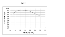
- FIG. 2 is an external view of a lithium ion secondary battery according to an embodiment to which the present invention is applicable. It is a figure which shows the relationship between the length of the primary particle of the carbon nanotube of embodiment which can apply this invention, and a battery characteristic. It is a figure which shows the relationship between the cycling characteristics of the lithium ion secondary battery of embodiment which can apply this invention, and high rate discharge capacity.
- FIG. 1 (A) is a schematic view showing the inside of a lithium ion secondary battery which is an embodiment of the nonaqueous electrolyte battery of the present invention in a transparent state
- FIG. 1 (B) is FIG. 1 (A).
- FIG. 1C is an external view of a lithium ion secondary battery which is an embodiment of the non-aqueous electrolyte battery of the present invention.
- the lithium ion secondary battery (laminated battery 1) includes a positive electrode plate 2 including a positive electrode lead terminal 2a, a negative electrode plate 3 including a negative electrode lead terminal 3a, and a separator disposed between the positive electrode plate 2 and the negative electrode plate 3. 4 and a nonaqueous electrolytic solution 5 in which a lithium salt is dissolved in an organic solvent.
- the positive electrode plate 2, the negative electrode plate 3, and the separator 4 constitute an electrode plate group 6 that is a laminate.
- the electrode plate group 6 is housed in the case 7 with the positive electrode lead terminal 2a and the negative electrode lead terminal 3a being connectable to the outside.
- the inside of the case 7 is evacuated with the nonaqueous electrolyte 5 filled.
- such a lithium ion secondary battery 1 was produced as follows.
- the lithium ion secondary battery of this embodiment is characterized in that carbon nanotubes are used as the carbon-based conductive material of the negative electrode active material.
- a negative electrode current collector coated with a negative electrode active material and a positive electrode current collector coated with a positive electrode active material are stacked with a separator interposed therebetween and impregnated with an electrolytic solution.
- carbon nanotubes as a conductive material are dispersed almost uniformly between the particles of the negative electrode active material.
- the BET specific surface area of the carbon nanotubes is desirably 200 m 2 / g or more and 300 m 2 / g or less.
- the BET specific surface area of the carbon nanotube is less than 200 m 2 / g, the effect of reducing the electronic resistance by adding a small amount of the carbon nanotube is small.
- the BET specific surface area of the carbon nanotubes exceeds 300 m 2 / g, a large amount of binder is required when preparing the negative electrode slurry, and thus a large amount of binder is required, making it difficult to prepare the slurry. .
- the carbon nanotube used for the negative electrode conductive material has higher electronic conductivity than known conductive materials such as acetylene black, the addition of the carbon nanotube can reduce the electronic resistance of the electrode.
- the contact area between the current collector and the mixture layer increases when added, and the fibrous carbon nanotubes work as an anchor material, improving adhesion. Cycle characteristics can be improved.
- the addition amount is 0.5% by weight or more and 1.5% by weight or less with respect to the weight of the negative electrode active material, the high rate discharge characteristics / cycle characteristics are improved, and the battery capacity is greatly reduced.
- the inventor found that there was no.
- the addition amount is less than 0.5% by weight, the effect as an anchor material is small and the influence on the cycle characteristics is small.
- the addition amount exceeds 1.5% by weight the battery capacity is greatly reduced due to an increase in the amount of SEI produced, and due to aggregation of primary particles, the dispersibility in the mixture is reduced, leading to an increase in electrode resistance.
- the primary particle length of the carbon nanotube is 5 to 20 ⁇ m. If the length of the primary particles is less than 5 ⁇ m, the formation of a conductive path due to the addition of a small amount is insufficient, and if it exceeds 20 ⁇ m, the effect on the electronic resistance of the electrode is reduced due to aggregation of the conductive material.
- the amount of carbon nanotubes added to the negative electrode active material is 0.5% by weight or more. It is desirable that it is 1.5% by weight or less, and the primary particle length is in the range of 5 to 20 ⁇ m.
- the porosity of the negative electrode mixture is preferably 25 to 40% from the viewpoint of maintaining discharge characteristics such as high discharge capacity and large current discharge.
- the porosity is less than 25%, the ion permeability or ion conductivity is lowered, so that the discharge characteristics are lowered.
- the porosity exceeds 40%, the adhesion between the negative electrode mixture layer and the negative electrode current collector is lowered, so that the electron transfer resistance is increased and the discharge characteristics are lowered.
- the positive electrode active material is not particularly limited as long as it absorbs positive ions or discharges negative ions during discharge, and a metal oxide such as LiMnO 2 , LiMn 2 O 4 , LiCoO 2 , LiNiO 2 can be used. .
- An aluminum foil or the like can be used as the positive electrode current collector.
- the negative electrode active material is not particularly limited as long as it is a material capable of occluding and releasing cations.
- Crystalline carbon such as graphitized carbon obtained by heat treatment of natural graphite, coal, petroleum pitch, etc., coal, petroleum Amorphous carbon obtained by heat-treating pitch coke, acetylene pitch coke or the like can be used.
- a copper foil or the like can be used as the negative electrode current collector.
- the current collector a known material such as a metal foil such as copper or nickel can be appropriately used.
- the thickness of the metal foil at this time may generally be about 10 ⁇ m.
- the material for the current collector include metals selected from copper, nickel, iron, aluminum, zinc, gold, platinum, and the like.
- the positive electrode current collector is preferably aluminum from the viewpoint of high oxidation resistance.
- the binder plays a role of bonding the particles of the active material, the active material and the conductive material, and the active material and the current collector.
- the binder for example, polyvinylidene fluoride, polyvinyl pyridine, polytetrafluoroethylene, styrene butadiene rubber, or the like can be used.
- electrolytic solution examples include ethylene carbonate, propylene carbonate, dimethyl carbonate, diethyl carbonate, methyl ethyl carbonate, ⁇ -butyrolactone, N, N′-dimethylformamide, dimethyl sulfoxide, N-methylpyrrolidone, and m-cresol.
- Examples of highly polar solvents that can be used as electrolytes for secondary batteries include alkali metal cations such as Li, K, and Na, ClO 4 ⁇ , BF 4 ⁇ , PF 6 ⁇ , CF 3 SO 3 ⁇ , and (CF 3 SO 2 ) 2 N -, (C 2 F 5 SO 2) 2 N -, (CF 3 SO 2) 3 C -, (C 2 F 5 SO 2) 3 C - a salt composed of anions of a compound containing halogen such as It can be dissolved.
- the solvent and electrolyte salt which consist of these basic solvents can also be used individually or in combination.
- a lithium ion secondary battery using the carbon nanotube of the present invention as a conductive material for a negative electrode as a constituent member such as a positive electrode material and an electrolyte solution (electrolyte, solvent), etc.
- a constituent member such as a positive electrode material and an electrolyte solution (electrolyte, solvent), etc.
- electrolyte solution electrolyte, solvent
- Example 1 (Preparation of positive electrode plate) A lithium cobalt composite oxide (LiCoO 2 ) is prepared as a positive electrode active material for the positive electrode plate.
- This lithium cobalt composite oxide, acetylene black as a conductive agent, and polyvinylidene fluoride as a binder are mixed at a mass ratio of 90: 5: 5 and dispersed in a solvent of N-methylpyrrolidone.
- a slurry was prepared. This slurry was applied to an aluminum foil as a positive electrode current collector and dried, followed by press working to produce a positive electrode sheet.
- the positive electrode sheet on which such a coating layer was formed was cut out to 10 cm ⁇ 20 cm, and a current collecting tab of aluminum foil was welded to prepare a positive electrode plate 2.
- a positive electrode active material layer is formed on the surface of the positive electrode plate 2
- a flame retardant layer is further formed on the surface of the positive electrode active material layer.
- Artificial graphite is prepared as a negative electrode active material. This artificial graphite, a conductive agent, and polyvinylidene fluoride as a binder were mixed at a mass ratio of 92: 1: 7 and dispersed in a solvent of N-methylpyrrolidone to prepare a slurry.
- the slurry was applied on a copper foil as a negative electrode current collector and dried, and then subjected to press working to produce a negative electrode sheet.
- the negative electrode sheet was cut to 10 cm ⁇ 20 cm, and a nickel current collecting tab was welded to the cut sheet to prepare the negative electrode plate 3.
- the positive electrode plate 2, the negative electrode plate 3, and the separator 4 are laminated with the separator sheet (separator 4) made of polyethylene sandwiched between the positive electrode plate 2 and the negative electrode plate 3 thus manufactured, and the battery capacity becomes 1 Ah.
- the electrode group 6 was produced.
- a mixed solvent consisting of 50% by volume of ethylene carbonate and 50% by volume of dimethyl carbonate was prepared.
- LiPF 6 was dissolved in this mixed solvent so as to have a concentration of 1 mol / L to prepare an electrolyte solution.
- the prepared electrode plate group 6 is inserted into an outer packaging material (which will later be a case 7) made of a heat-sealing film (aluminum laminate film), and the prepared non-aqueous electrolyte 4 is further contained in the outer packaging material. Injected into. Then, the inside of the exterior material was evacuated, and the opening of the exterior material was quickly heat-sealed to produce a non-aqueous electrolyte battery (lithium ion secondary battery) having the structure of the flat laminate battery 1. (Evaluation of battery characteristics) The battery characteristics of the non-aqueous electrolyte battery thus produced were evaluated by the methods shown below.
- the battery characteristics of the produced nonaqueous electrolyte battery were evaluated. Specifically, the discharge characteristics of the battery in which the type of the negative electrode conductive material was changed were evaluated. Note that the addition amount of the conductive material was 1.0 wt% with respect to the negative electrode active material.
- the evaluation results of the discharge characteristics are as shown in Table 1.
- the charge / discharge efficiency in Table 1 means a 0.2C discharge capacity with respect to the initial charge capacity.
- the battery characteristics were evaluated by a high rate discharge test.
- a charge / discharge cycle with a current value of 0.2 C was repeated twice in a voltage range of 4.2 to 3.0 V in an environment of 25 ° C. Further, after charging the battery to 4.2 V, charging / discharging was performed by constant current discharge with a final voltage of 3.0 V at current values of 0.2 C, 1 C, and 3 C.
- the carbon nanotube is a fibrous material with very small primary particles of about 10 nm, it is considered that the addition of carbon nanotubes enters between the negative electrode active materials and electrically connects the negative electrode active materials.
- Example 2 In preparation of the negative electrode 2, lithium was sputtered on a part of the negative electrode active material coating portion. A lithium film having a length of 200 mm and a width of 60 mm was formed at intervals of 200 mm from the end in the longitudinal direction of the negative electrode active material coating portion.
- the lithium film was formed by forming a lithium film at 15 locations with a negative electrode having a length of 3000 mm.
- the total area of the formed lithium film was 50% of the total area of the negative electrode active material coating part.
- the average was 13.8 ⁇ m (minimum thickness 12.3 ⁇ m, maximum thickness 14.7 ⁇ m).
- Others were the same as in Example 1, and cells 2a and 2b were produced. (Characteristic evaluation of cells 2a and 2b) Similarly to Example 1, the cell capacity and internal resistance of the cell 2a were evaluated.
- Example 2 the capacity
- FIG. (Examples 2 to 6)
- the charging pattern each lithium battery was subjected to constant current charging at 0.2 C up to an upper limit voltage of 4.2 V, followed by constant voltage charging at 4.2 V.
- the discharge was performed at a constant current of 3C up to 3.0V. Note that the addition amount of the conductive material was 1.0 wt% with respect to the negative electrode active material.
- carbon nanotubes which are carbon-based conductive materials, have superior performance in charge / discharge efficiency and discharge characteristics as compared with acetylene black and carbon nanohorns.
- the carbon nanotubes themselves exhibit excellent characteristics, and in particular, batteries with carbon nanotubes having a specific surface area of 200 to 300 m 2 / g exhibit good high rate discharge characteristics.
- the specific surface area is less than 200 m 2 / g, the influence on the discharge characteristics with the same addition amount is reduced due to the reduction of the contact area with the active material.
- the specific surface area exceeds 300 m 2 / g, uniform dispersion becomes difficult due to aggregation of the conductive material, and the effect for reducing the resistance becomes somewhat insufficient.
- the specific surface area of the carbon nanotube to be added is preferably in the range of 200 to 300 m 2 / g. (Example 7) Next, in the laminated battery 1, the relationship between the type of the negative electrode conductive material and the life characteristics was confirmed.
- each lithium battery was subjected to constant current charging at 0.2 C up to an upper limit voltage of 4.2 V, followed by constant voltage charging at 4.2 V.
- the discharge was performed at a constant current of 1 C up to 3.0 V. Note that the addition amount of the conductive material was 1.0 wt% with respect to the negative electrode active material.
- Table 3 shows the test results.
- the capacity maintenance rate in Table 3 represents the discharge capacity ratio at the 50th cycle with respect to the initial discharge capacity.
- a battery having a primary particle length of carbon nanotube of 5 to 20 ⁇ m exhibits good high rate discharge characteristics. If the length of the primary particles is less than 5 ⁇ m, the primary particles are too small and the particles are aggregated, making it difficult to enter between the active materials. For this reason, a favorable conductive path cannot be formed, and the effect of reducing the electronic resistance of the electrode becomes insufficient.
- the length of the primary particles exceeds 20 ⁇ m, the molecular chains are entangled with each other and only adhere to the surface. For this reason, the negative electrode active materials cannot be electrically connected to each other and function as a resistance component, so that the high rate discharge characteristics are deteriorated.
- the primary particle length of the carbon nanotube to be added is preferably in the range of 5 to 20 ⁇ m, particularly preferably in the range of 10 to 15 ⁇ m.
- Examples 12 to 14 Next, in the laminated battery 1, the relationship between the amount of carbon nanotube added and the battery characteristics was confirmed. Specifically, the high rate discharge capacity and cycle characteristics were confirmed for the batteries in which the amount of carbon nanotube added was changed. The fiber length of the carbon nanotube was 10 ⁇ m.
- the test results are shown in Table 5 and FIG.
- the initial capacity in FIG. 3 means a 0.2C discharge capacity ratio in each cycle with respect to the initial discharge capacity.
- the high rate discharge characteristics tended to increase by increasing the amount of carbon nanotube added. However, an increase in irreversible capacity was observed with the addition. For this reason, when the addition amount exceeds 1.5 wt%, the internal resistance due to the generated SEI increases, and the effect of improving the high rate discharge characteristics becomes small. If the addition amount is less than 0.5 wt%, the effect of reducing the electronic resistance due to the addition is insufficient, and if it exceeds 1.5 wt%, the high rate discharge characteristics may be caused by a decrease in battery capacity due to an increase in SEI or an increase in internal resistance. descend.
- the addition amount was 0.5 wt% or more, the capacity ratio in 3C discharge exceeded 90%, and the efficiency discharge characteristics were greatly improved.
- the absolute value of the 3C discharge capacity is an increase rate of less than 1% in a battery in which the amount of carbon nanotubes added is 2.0 wt%. If the increase rate of the irreversible capacity is less than 1%, it is considered that the influence due to the increase of the irreversible capacity appears larger than the improvement effect of the high rate discharge characteristics by the addition of the carbon nanotubes.
- the amount of carbon nanotubes added is preferably in the range of 0.5 wt% to 1.5 wt%.
- the addition amount is 0.2 wt%, the effect of suppressing the volume expansion of the graphite due to the addition is small, and when 2.0 wt%, the cycle characteristics deteriorate due to the increase in internal resistance.
- the amount of carbon nanotube added is in the range of 0.5 wt% to 1.5 wt%, the capacity retention rate after 100 cycles has exceeded 96%, confirming that good cycle characteristics can be obtained. did.
- the addition amount of carbon nanotubes is preferably in the range of 0.5 wt% to 1.5 wt% for improving the cycle characteristics.
- the porosity of the negative electrode mixture is preferably in the range of 25 to 40%, particularly preferably in the range of 30 to 35 ⁇ m.
- carbon nanotubes are added as a conductive material to the negative electrode, and the added amount is 0.5 to 1.5% by weight with respect to the weight of the negative electrode active material, so that high rate charge / discharge characteristics / cycle characteristics
- a lithium ion secondary battery that does not significantly reduce battery capacity can be provided.
- SYMBOLS 1 Lithium ion secondary battery, 2 ... Positive electrode plate, 3 ... Negative electrode plate, 4 ... Separator, 5 ... Non-aqueous electrolyte, 6 ... Electrode plate group, 7 ... Case.
Landscapes
- Chemical & Material Sciences (AREA)
- Chemical Kinetics & Catalysis (AREA)
- Electrochemistry (AREA)
- General Chemical & Material Sciences (AREA)
- Engineering & Computer Science (AREA)
- Materials Engineering (AREA)
- Manufacturing & Machinery (AREA)
- Battery Electrode And Active Subsutance (AREA)
- Secondary Cells (AREA)
Abstract
Cette invention concerne un accumulateur lithium-ion présentant une durée de vie étendue ainsi qu'une réduction de la résistance de l'électrode et de la capacité irréversible. Ledit accumulateur lithium-ion comprend : un boîtier contenant un liquide électrolytique non aqueux ainsi qu'un groupe d'électrodes planes constitué d'une électrode plane positive formée d'une couche composite d'électrode positive contenant une substance active et formée au-dessus d'un collecteur de courant, et d'une électrode plane négative formée d'une couche composite d'électrode négative contenant une substance active et un matériau conducteur à base de carbone et formée au-dessus d'un collecteur de courant, disposées de part et d'autre d'un séparateur. Le matériau conducteur à base de carbone est constitué de nanotubes de carbone.
Priority Applications (1)
| Application Number | Priority Date | Filing Date | Title |
|---|---|---|---|
| JP2013512326A JPWO2012147647A1 (ja) | 2011-04-27 | 2012-04-20 | リチウムイオン二次電池 |
Applications Claiming Priority (2)
| Application Number | Priority Date | Filing Date | Title |
|---|---|---|---|
| JP2011099863 | 2011-04-27 | ||
| JP2011-099863 | 2011-04-27 |
Publications (1)
| Publication Number | Publication Date |
|---|---|
| WO2012147647A1 true WO2012147647A1 (fr) | 2012-11-01 |
Family
ID=47072167
Family Applications (1)
| Application Number | Title | Priority Date | Filing Date |
|---|---|---|---|
| PCT/JP2012/060710 Ceased WO2012147647A1 (fr) | 2011-04-27 | 2012-04-20 | Accumulateur lithium-ion |
Country Status (2)
| Country | Link |
|---|---|
| JP (1) | JPWO2012147647A1 (fr) |
| WO (1) | WO2012147647A1 (fr) |
Cited By (7)
| Publication number | Priority date | Publication date | Assignee | Title |
|---|---|---|---|---|
| JP2016110876A (ja) * | 2014-12-08 | 2016-06-20 | 三星エスディアイ株式会社Samsung SDI Co., Ltd. | リチウムイオン二次電池用負極、およびリチウムイオン二次電池 |
| CN105849946A (zh) * | 2013-12-24 | 2016-08-10 | 日进电气有限公司 | 用于锂二次电池的阴极板 |
| JP2017174527A (ja) * | 2016-03-22 | 2017-09-28 | 住友金属鉱山株式会社 | 評価用リチウムイオン二次電池の製造方法、および評価用リチウムイオン二次電池 |
| WO2020175172A1 (fr) | 2019-02-27 | 2020-09-03 | パナソニックIpマネジメント株式会社 | Batterie secondaire à électrolyte non aqueux de type à enroulement |
| CN113728469A (zh) * | 2020-06-30 | 2021-11-30 | 宁德新能源科技有限公司 | 电化学装置和电子装置 |
| WO2023149529A1 (fr) * | 2022-02-07 | 2023-08-10 | パナソニックエナジ-株式会社 | Batterie secondaire à électrolyte non aqueux |
| CN116848676A (zh) * | 2021-02-26 | 2023-10-03 | 松下知识产权经营株式会社 | 电池用电极合剂和非水电解质二次电池 |
Citations (9)
| Publication number | Priority date | Publication date | Assignee | Title |
|---|---|---|---|---|
| JP2002134115A (ja) * | 2000-10-23 | 2002-05-10 | Takiron Co Ltd | リチウムイオン2次電池用導電性バインダー液、該バインダー液の製造方法および該バインダー液を用いたリチウムイオン2次電池用電極材 |
| JP2004134304A (ja) * | 2002-10-11 | 2004-04-30 | Hitachi Maxell Ltd | 非水二次電池および正極塗料製造方法 |
| JP2004273433A (ja) * | 2003-02-19 | 2004-09-30 | Matsushita Electric Ind Co Ltd | 電池用電極およびその製造法 |
| JP2004319186A (ja) * | 2003-04-14 | 2004-11-11 | Sony Corp | 非水電解質電池 |
| JP2005004974A (ja) * | 2003-06-09 | 2005-01-06 | Matsushita Electric Ind Co Ltd | リチウムイオン二次電池 |
| WO2005086260A1 (fr) * | 2004-03-03 | 2005-09-15 | Sanyo Electric Co., Ltd | Batterie électrolytique non aqueuse |
| JP2008218248A (ja) * | 2007-03-06 | 2008-09-18 | Hitachi Powdered Metals Co Ltd | リチウム二次電池 |
| JP2010123437A (ja) * | 2008-11-20 | 2010-06-03 | Automotive Energy Supply Corp | リチウムイオン電池 |
| JP2010225366A (ja) * | 2009-03-23 | 2010-10-07 | Sanyo Electric Co Ltd | 非水電解質二次電池 |
-
2012
- 2012-04-20 JP JP2013512326A patent/JPWO2012147647A1/ja active Pending
- 2012-04-20 WO PCT/JP2012/060710 patent/WO2012147647A1/fr not_active Ceased
Patent Citations (9)
| Publication number | Priority date | Publication date | Assignee | Title |
|---|---|---|---|---|
| JP2002134115A (ja) * | 2000-10-23 | 2002-05-10 | Takiron Co Ltd | リチウムイオン2次電池用導電性バインダー液、該バインダー液の製造方法および該バインダー液を用いたリチウムイオン2次電池用電極材 |
| JP2004134304A (ja) * | 2002-10-11 | 2004-04-30 | Hitachi Maxell Ltd | 非水二次電池および正極塗料製造方法 |
| JP2004273433A (ja) * | 2003-02-19 | 2004-09-30 | Matsushita Electric Ind Co Ltd | 電池用電極およびその製造法 |
| JP2004319186A (ja) * | 2003-04-14 | 2004-11-11 | Sony Corp | 非水電解質電池 |
| JP2005004974A (ja) * | 2003-06-09 | 2005-01-06 | Matsushita Electric Ind Co Ltd | リチウムイオン二次電池 |
| WO2005086260A1 (fr) * | 2004-03-03 | 2005-09-15 | Sanyo Electric Co., Ltd | Batterie électrolytique non aqueuse |
| JP2008218248A (ja) * | 2007-03-06 | 2008-09-18 | Hitachi Powdered Metals Co Ltd | リチウム二次電池 |
| JP2010123437A (ja) * | 2008-11-20 | 2010-06-03 | Automotive Energy Supply Corp | リチウムイオン電池 |
| JP2010225366A (ja) * | 2009-03-23 | 2010-10-07 | Sanyo Electric Co Ltd | 非水電解質二次電池 |
Cited By (13)
| Publication number | Priority date | Publication date | Assignee | Title |
|---|---|---|---|---|
| CN105849946A (zh) * | 2013-12-24 | 2016-08-10 | 日进电气有限公司 | 用于锂二次电池的阴极板 |
| JP2017501546A (ja) * | 2013-12-24 | 2017-01-12 | イルジン エレクトリック カンパニー リミテッド | リチウム二次電池用負極板 |
| JP2016110876A (ja) * | 2014-12-08 | 2016-06-20 | 三星エスディアイ株式会社Samsung SDI Co., Ltd. | リチウムイオン二次電池用負極、およびリチウムイオン二次電池 |
| JP7053130B2 (ja) | 2014-12-08 | 2022-04-12 | 三星エスディアイ株式会社 | リチウムイオン二次電池用負極、およびリチウムイオン二次電池 |
| JP7043162B2 (ja) | 2016-03-22 | 2022-03-29 | 住友金属鉱山株式会社 | 評価用リチウムイオン二次電池の製造方法、および評価用リチウムイオン二次電池 |
| JP2017174527A (ja) * | 2016-03-22 | 2017-09-28 | 住友金属鉱山株式会社 | 評価用リチウムイオン二次電池の製造方法、および評価用リチウムイオン二次電池 |
| WO2020175172A1 (fr) | 2019-02-27 | 2020-09-03 | パナソニックIpマネジメント株式会社 | Batterie secondaire à électrolyte non aqueux de type à enroulement |
| US12068479B2 (en) | 2019-02-27 | 2024-08-20 | Panasonic Intellectual Property Management Co., Ltd. | Winding-type nonaqueous electrolyte secondary battery |
| US12444743B2 (en) | 2019-02-27 | 2025-10-14 | Panasonic Intellectual Property Management Co., Ltd. | Winding-type nonaqueous electrolyte secondary battery |
| CN113728469A (zh) * | 2020-06-30 | 2021-11-30 | 宁德新能源科技有限公司 | 电化学装置和电子装置 |
| CN113728469B (zh) * | 2020-06-30 | 2023-05-09 | 宁德新能源科技有限公司 | 电化学装置和电子装置 |
| CN116848676A (zh) * | 2021-02-26 | 2023-10-03 | 松下知识产权经营株式会社 | 电池用电极合剂和非水电解质二次电池 |
| WO2023149529A1 (fr) * | 2022-02-07 | 2023-08-10 | パナソニックエナジ-株式会社 | Batterie secondaire à électrolyte non aqueux |
Also Published As
| Publication number | Publication date |
|---|---|
| JPWO2012147647A1 (ja) | 2014-07-28 |
Similar Documents
| Publication | Publication Date | Title |
|---|---|---|
| JP5462445B2 (ja) | リチウムイオン二次電池 | |
| JP5519586B2 (ja) | リチウムイオン二次電池用電極及びその製造方法、並びにリチウムイオン二次電池及びその製造方法 | |
| CN110313089B (zh) | 非水电解质二次电池用负极和非水电解质二次电池 | |
| KR101907700B1 (ko) | 리튬 이차 전지용 전극재 및 리튬 이차 전지 | |
| JP5797993B2 (ja) | 非水電解質二次電池 | |
| JP5832729B2 (ja) | 二次電池用電極及び非水電解液電池 | |
| JP4834030B2 (ja) | リチウム二次電池用正極及びこれを用いたリチウム二次電池 | |
| JP6769334B2 (ja) | 非水電解質蓄電素子用の負極、非水電解質蓄電素子及び非水電解質蓄電素子用の負極の製造方法 | |
| CN102549819B (zh) | 非水电解液型锂离子二次电池 | |
| WO2016157735A1 (fr) | Pile rechargeable à électrolyte non aqueux | |
| KR20130129819A (ko) | 리튬 이온 이차 전지 | |
| JP5505480B2 (ja) | リチウムイオン二次電池用負極及びその負極を用いたリチウムイオン二次電池 | |
| WO2012147647A1 (fr) | Accumulateur lithium-ion | |
| KR20210058172A (ko) | 음극 및 상기 음극을 포함하는 이차 전지 | |
| JP7782924B2 (ja) | 正極およびそれを含む二次電池 | |
| JP2013073705A (ja) | リチウムイオン二次電池 | |
| JP6950342B2 (ja) | 負極及び非水電解質蓄電素子 | |
| JP2016134218A (ja) | リチウムイオン二次電池 | |
| JP6061143B2 (ja) | リチウムイオン二次電池用正極及びリチウムイオン二次電池 | |
| US20230102905A1 (en) | Nonaqueous electrolyte energy storage device | |
| CN113054160A (zh) | 非水电解质二次电池用负极、和非水电解质二次电池 | |
| WO2015132845A1 (fr) | Batterie tout solide | |
| JP7003775B2 (ja) | リチウムイオン二次電池 | |
| JP2014149989A (ja) | リチウムイオン二次電池用活物質、それを有するリチウムイオン二次電池用電極及びリチウムイオン二次電池 | |
| JP2014225327A (ja) | 非水電解質二次電池 |
Legal Events
| Date | Code | Title | Description |
|---|---|---|---|
| 121 | Ep: the epo has been informed by wipo that ep was designated in this application |
Ref document number: 12776798 Country of ref document: EP Kind code of ref document: A1 |
|
| ENP | Entry into the national phase |
Ref document number: 2013512326 Country of ref document: JP Kind code of ref document: A |
|
| NENP | Non-entry into the national phase |
Ref country code: DE |
|
| 122 | Ep: pct application non-entry in european phase |
Ref document number: 12776798 Country of ref document: EP Kind code of ref document: A1 |