WO2012147655A1 - Système de calcul de force - Google Patents
Système de calcul de force Download PDFInfo
- Publication number
- WO2012147655A1 WO2012147655A1 PCT/JP2012/060731 JP2012060731W WO2012147655A1 WO 2012147655 A1 WO2012147655 A1 WO 2012147655A1 JP 2012060731 W JP2012060731 W JP 2012060731W WO 2012147655 A1 WO2012147655 A1 WO 2012147655A1
- Authority
- WO
- WIPO (PCT)
- Prior art keywords
- air
- flow
- unit
- flow path
- flow rate
- Prior art date
- Legal status (The legal status is an assumption and is not a legal conclusion. Google has not performed a legal analysis and makes no representation as to the accuracy of the status listed.)
- Ceased
Links
Images



Classifications
-
- G—PHYSICS
- G01—MEASURING; TESTING
- G01L—MEASURING FORCE, STRESS, TORQUE, WORK, MECHANICAL POWER, MECHANICAL EFFICIENCY, OR FLUID PRESSURE
- G01L1/00—Measuring force or stress, in general
- G01L1/02—Measuring force or stress, in general by hydraulic or pneumatic means
-
- G—PHYSICS
- G01—MEASURING; TESTING
- G01F—MEASURING VOLUME, VOLUME FLOW, MASS FLOW OR LIQUID LEVEL; METERING BY VOLUME
- G01F1/00—Measuring the volume flow or mass flow of fluid or fluent solid material wherein the fluid passes through a meter in a continuous flow
- G01F1/05—Measuring the volume flow or mass flow of fluid or fluent solid material wherein the fluid passes through a meter in a continuous flow by using mechanical effects
- G01F1/20—Measuring the volume flow or mass flow of fluid or fluent solid material wherein the fluid passes through a meter in a continuous flow by using mechanical effects by detection of dynamic effects of the flow
- G01F1/206—Measuring pressure, force or momentum of a fluid flow which is forced to change its direction
-
- G—PHYSICS
- G01—MEASURING; TESTING
- G01F—MEASURING VOLUME, VOLUME FLOW, MASS FLOW OR LIQUID LEVEL; METERING BY VOLUME
- G01F1/00—Measuring the volume flow or mass flow of fluid or fluent solid material wherein the fluid passes through a meter in a continuous flow
- G01F1/05—Measuring the volume flow or mass flow of fluid or fluent solid material wherein the fluid passes through a meter in a continuous flow by using mechanical effects
- G01F1/20—Measuring the volume flow or mass flow of fluid or fluent solid material wherein the fluid passes through a meter in a continuous flow by using mechanical effects by detection of dynamic effects of the flow
- G01F1/28—Measuring the volume flow or mass flow of fluid or fluent solid material wherein the fluid passes through a meter in a continuous flow by using mechanical effects by detection of dynamic effects of the flow by drag-force, e.g. vane type or impact flowmeter
-
- G—PHYSICS
- G01—MEASURING; TESTING
- G01L—MEASURING FORCE, STRESS, TORQUE, WORK, MECHANICAL POWER, MECHANICAL EFFICIENCY, OR FLUID PRESSURE
- G01L1/00—Measuring force or stress, in general
- G01L1/04—Measuring force or stress, in general by measuring elastic deformation of gauges, e.g. of springs
- G01L1/042—Measuring force or stress, in general by measuring elastic deformation of gauges, e.g. of springs of helical springs
Definitions
- the present invention relates to a technique for calculating a force applied to a target portion for calculating a force without using an electrical device.
- a strain gauge using a change in electrical resistance (hereinafter referred to as “electric strain sensor”) and a load cell having a piezoelectric element mounted on a sensing part have been widely used.
- electrical strain sensor a strain gauge using a change in electrical resistance
- load cell having a piezoelectric element mounted on a sensing part
- MRI Magnetic Resonance Imaging
- optical fiber sensor an optical fiber strain gauge (hereinafter referred to as “optical fiber sensor”) has been put into practical use (see Non-Patent Documents 1 and 2). According to this technique, since changes in the wavelength, frequency, phase, transmission amount, etc. of light due to distortion of the sensing part are detected, the above-described problems caused by the electrical elements do not occur.
- an optical switch as a light source and a signal conditioner for signal processing are required, and the configuration of the entire system is large and expensive compared to an electric strain sensor. .
- the present invention has been made in view of such circumstances, and is small and inexpensive, and the force applied to the part without using an electrical device for the target part for calculating the force. It is an object of the present invention to provide a force calculation system that calculates
- a force calculation system includes an air delivery unit that sends out air at a predetermined pressure, and a flow path for air that is connected to the air delivery unit and that is sent from the air delivery unit. And a sensing part that is provided at a position opposite to the air delivery part in the flow path and deforms when receiving an external force, thereby changing the ease of flow of the air flowing through the flow path, and the flow A flow meter that measures the flow rate of the air flowing through the path, the magnitude of the external force received by the sensing unit, and correspondence information of the flow rate of the air that is sent from the air sending unit flows through the flow path are stored in advance. Based on the storage unit, the flow rate of the air flowing through the flow path measured by the flowmeter, and the correspondence information stored in the storage unit, the magnitude of the external force received by the sensing unit is calculated. And a processing unit. That.
- FIG. 1 It is a whole lineblock diagram of the force calculation system of this embodiment.
- It is a block diagram of a tube pinching type sensing part (a) is a figure which shows the state before receiving external force, (b) is a figure which shows the state after receiving external force.
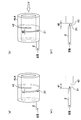
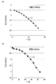
- It is a block diagram of a slit type sensing part (a) is a figure which shows the state before receiving external force, (b) is a figure which shows the state after receiving external force. It is a figure which shows the relationship between the external force given to a sensing part, and the flow volume of the air which flows through a flow path, (a) is a figure which shows an example in the case of a tube pinching type, (b) is an example in the case of a slit type.
- the force calculation system 100 of the present embodiment is, for example, a repulsive force from a visceral viscera applied to an entire forceps used in an endoscopic surgical robot (hereinafter simply referred to as “surgical robot”), or a suturing operation. It is assumed that it is used when calculating the tension of the yarn at the time.
- the force calculation system 100 includes an air delivery unit 1, a flow path 2, a flow meter 3, a sensor unit 4, and a calculation device 5.
- the air delivery unit 1 is a means for delivering air at a predetermined pressure, and can be realized by, for example, a combination of a compressor and a pressure reducing valve.
- the flow path 2 is connected to the air delivery section 1 and is a flow path for the air delivered from the air delivery section 1, and can be realized by a resin tube, for example.
- the sensitive part 4 side is also referred to as a distal end (part), and the air delivery part 1 side is also referred to as a proximal end (part).
- the flow meter 3 is a means for measuring the flow rate of air flowing through the flow path 2 and can be realized by, for example, a laminar flow meter (a laminar flow element and a differential pressure sensor at both ends).
- the sensing part 4 is provided at the tip of the flow path 2 and is a means for changing the ease of flow of air flowing through the flow path 2 by being deformed when receiving an external force (details will be described later).
- the arithmetic device 5 is a computer device and includes a receiving unit 51, a processing unit 52, a storage unit 53, an input unit 54, and an output unit 55.
- the receiving unit 51 is means for receiving flow rate measurement data from the flow meter 3 and can be realized by, for example, a dedicated IC (Integrated Circuit).
- the processing unit 52 is a means for performing various arithmetic processes, and can be realized by, for example, a CPU (Central Processing Unit).
- the processing unit 52 receives the sensitivity based on the measurement data of the flow rate of the air flowing through the flow path 2 measured by the flow meter 3 and the flow rate / force correspondence information 531 (correspondence relationship information) stored in the storage unit 53.
- the magnitude of the external force received by the unit 4 is calculated (details will be described later).
- the storage unit 53 is a means for storing information, and can be realized by, for example, a RAM (Random Access Memory), a ROM (Read Only Memory), an HDD (Hard Disk Drive), or the like.
- the storage unit 53 includes flow rate / force correspondence information 531 indicating the correspondence between the magnitude of external force received by the sensing unit 4 and the flow rate of the air sent from the air delivery unit 1 through the flow path 2. Is memorized.
- the flow rate / force correspondence information 531 is information obtained by converting a graph shown in FIGS. 3A and 3B described later into data.
- the input unit 54 is a means for the user of the arithmetic device 5 to input information, and can be realized by a keyboard or a mouse, for example.
- the output unit 55 is a means for outputting information, and can be realized by, for example, an external communication interface, LCD (Liquid Crystal Display), or the like.
- the tube sandwiching type sensing unit 4 will be described.
- the tube sandwiching type sensing parts 4a and 4 are made of stainless steel and can be realized by a coil spring (elastic body) in which a middle part of a cylindrical body is formed in a coil shape. .
- a midway part 22 in the vicinity of the tip part 21 of the flow path 2 is sandwiched in the gap 41 of the sensing part 4a.
- the flow path 2 needs to be an elastically deformable tube.
- the size of the sensing part 4a is, for example, about 5 mm in diameter and about 20 mm in length in the axial direction.
- the slit type sensing part 4 As shown in FIG. 2B (a), the slit-type sensing parts 4b, 4 are entirely made of cylindrical aluminum, and the interval between the openings is reduced when an external force is applied in the axial direction (predetermined direction). It has a slit 42 that changes. In addition, a hole through which the distal end portion 21 of the flow channel 2 can be inserted to the slit 42 is provided in a part of the side wall, and the flow channel 2 is disposed at a position where the distal end portion 21 opens into the slit 42.
- the flow path 2 does not need to be elastically deformable.
- the size of the sensing part 4b is, for example, about 10 mm in diameter and about 15 mm in the axial length.
- the tip 21 of the flow path 2 is separated from the facing surface 43 by the width d1 of the slit 42.
- the sensing part 4 is applied to tasks (such as surgery) whose operating frequency is 2 to 3 Hz or less. It can be said that has been realized.
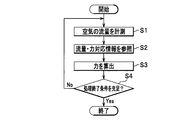
- the receiving unit 51 of the arithmetic device 5 measures the flow rate of the air flowing through the flow path 2 (step S1). Specifically, the receiving unit 51 receives measurement data of the flow rate of air flowing through the flow path 2 from the flow meter 3, and the processing unit 52 grasps (measures) the flow rate of air flowing through the flow path 2 based on the measurement data. )
- the processing unit 52 refers to the flow rate / force correspondence relationship information 531 in the storage unit 53 (step S2), and the flow rate / force correspondence relationship information 531 and the flow rate of air flowing through the flow path 2 measured in step S1. Based on the above, the force (external force) received by the sensor unit 4 is calculated (step S3).
- the force calculation system 100 is applied to a surgical robot, for example, feedback control that mechanically reproduces and applies the force calculated in step S3 to a doctor operating remotely may be performed.
- the processing unit 52 determines whether or not the processing end condition is satisfied (step S4). If Yes, the processing ends, and if No, the processing returns to step S1.
- the processing end condition may be, for example, a manual operation such as an input operation in the input unit 54 by the user, or a condition that the external force on the sensing unit 4 has not been for a predetermined time (for example, 5 minutes). It may be automatic.
- the sensor is provided at the tip of the flow path 2 and deforms when receiving an external force to change the ease of flow of air flowing through the flow path 2. 4 and the flow rate / force correspondence information 531 stored in the storage unit 53 are used to calculate the magnitude of the external force received by the sensing unit 4.
- the force calculation system 100 that calculates the force applied to the portion can be realized without using an electrical device. More specifically, the sensing part 4 can be realized by either a tube sandwiching type or a slit type.
- the air flow rate is a detection target, it can be used without any trouble even in an electromagnetic environment such as an MRI apparatus or an explosion-proof environment such as a nuclear power plant.
- the structure of the sensing part 4 is simple, it can be reduced in size, the number of parts can be reduced, and low cost and high durability can be realized.
- the sensing part 4 can be attached also to such a forceps.
- the entire system can be made compact by utilizing the air delivery unit 1.
- the sensing part 4 is made of a metal such as stainless steel or aluminum, it can withstand sterilization washing at about 125 ° C. and can be applied to the medical field.
- the sensing section 4 and the flowmeter 3 are connected by the flow path 2 for circulating air, the degree of freedom in arrangement is high. That is, when an optical fiber sensor is used, the motion of the surgical robot may be hindered by the rigidity of the optical fiber arranged in the articulated surgical robot. In this embodiment, a low-rigidity channel 2 can be used. Therefore, such a problem can be easily avoided.
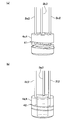
- the processing unit 52 of the arithmetic device 5 includes the three flow paths 2a, 2b, 2c based on the flow rates of air flowing through the three flow paths 2a, 2b, and 2c and the flow rate / force correspondence relationship information 531 of the storage unit 53.
- the magnitude of the received external force can be calculated for each of the tip portions 2b and 2c.
- the process part 52 can calculate the magnitude
- Corresponding flow rate / force correspondence relationship information 531 may be separately prepared for each of the three flow paths 2a, 2b, and 2c.
- three flow paths 2d, 2, 2e, 2, 2f, 2 are arranged at different positions.
- the flow rate of each air is measured by arranging a separate flow meter 3 for each of the three flow paths 2d, 2e, and 2f.
- the processing unit 52 of the arithmetic device 5 includes the three flow paths 2d, 2d, 2e, and 2f based on the flow rates of the air flowing through the three flow paths 2d, 2e, and 2f and the flow rate / force correspondence information 531 of the storage unit 53.
- the magnitude of the received external force can be calculated for each of the tip portions 2e and 2f.
- the process part 52 can calculate the magnitude
- Corresponding flow rate / force correspondence relationship information 531 may be separately prepared for each of the three flow paths 2d, 2e, and 2f.
- the magnitude and direction of force can be calculated by one sensing part 4 by using a plurality of flow paths 2.
- the aspect of the present invention is not limited to these.
- the material of the sensing part 4 is not limited to that described above, and may be other materials such as titanium and resin as long as they have the same elastic deformability.
- the coil sandwiching type sensing part 4 has been described by taking a coil spring as an example.
- the present invention is not limited to this, and the tube sandwiching type sensing part 4 has a gap for sandwiching the flow path 2 and changes the size of the gap when receiving external force. If so, other materials such as a leaf spring, a torsion spring, or an elastic body other than the spring may be used.
- the sensing part 4b may not be entirely cylindrical, but may be other shapes such as a square shape, and the spiral slit 42 may not be more than one but may be two or more. Furthermore, one or both of the bottom surface portions may be closed.
Landscapes
- Physics & Mathematics (AREA)
- General Physics & Mathematics (AREA)
- Fluid Mechanics (AREA)
- Measuring Volume Flow (AREA)
- Measurement Of The Respiration, Hearing Ability, Form, And Blood Characteristics Of Living Organisms (AREA)
- Force Measurement Appropriate To Specific Purposes (AREA)
Abstract
La présente invention concerne un système de calcul de force (100) comprenant : une unité de soufflage d'air (1) servant à souffler de l'air à une pression prédéterminée ; un canal (2) pour l'air soufflé par l'unité de soufflage d'air (1) ; une unité de détection (4) servant à modifier par déformation l'écoulement de l'air à travers le canal (2), quand une force externe est reçue ; une unité de stockage (53) servant à stocker à l'avance des informations de correspondance débit-force (531) représentant la correspondance entre l'intensité de la force reçue par l'unité de détection (4) et le débit de l'air soufflé par l'unité de soufflage d'air (1) à travers le canal ; et une unité de traitement (52) servant à calculer l'intensité d'une force externe reçue par l'unité de détection (4), sur la base du débit de l'air s'écoulant à travers le canal (2), mesuré par un débitmètre (3), et sur la base des informations de correspondance débit-force (531) stockées dans l'unité de stockage (53).
Priority Applications (2)
| Application Number | Priority Date | Filing Date | Title |
|---|---|---|---|
| EP12777692.0A EP2703796A4 (fr) | 2011-04-26 | 2012-04-20 | Système de calcul de force |
| US14/114,071 US9091605B2 (en) | 2011-04-26 | 2012-04-20 | Force calculating system |
Applications Claiming Priority (2)
| Application Number | Priority Date | Filing Date | Title |
|---|---|---|---|
| JP2011098178A JP5704712B2 (ja) | 2011-04-26 | 2011-04-26 | 力算出システム |
| JP2011-098178 | 2011-04-26 |
Publications (1)
| Publication Number | Publication Date |
|---|---|
| WO2012147655A1 true WO2012147655A1 (fr) | 2012-11-01 |
Family
ID=47072175
Family Applications (1)
| Application Number | Title | Priority Date | Filing Date |
|---|---|---|---|
| PCT/JP2012/060731 Ceased WO2012147655A1 (fr) | 2011-04-26 | 2012-04-20 | Système de calcul de force |
Country Status (4)
| Country | Link |
|---|---|
| US (1) | US9091605B2 (fr) |
| EP (1) | EP2703796A4 (fr) |
| JP (1) | JP5704712B2 (fr) |
| WO (1) | WO2012147655A1 (fr) |
Cited By (1)
| Publication number | Priority date | Publication date | Assignee | Title |
|---|---|---|---|---|
| US11221265B2 (en) | 2018-04-20 | 2022-01-11 | Mie Robot Exterior Technology Laboratory Co., Ltd. | Contact detecting device |
Families Citing this family (3)
| Publication number | Priority date | Publication date | Assignee | Title |
|---|---|---|---|---|
| JP5971638B1 (ja) | 2016-05-12 | 2016-08-17 | 株式会社三重木型製作所 | 接触検出装置 |
| CN108120739B (zh) * | 2018-01-24 | 2021-07-20 | 西安理工大学 | 一种针对高精密机床静压轴承的热变形测量装置 |
| CN108972601B (zh) * | 2018-08-10 | 2024-03-26 | 佛山科学技术学院 | 一种可感知三维力的末端执行器 |
Citations (6)
| Publication number | Priority date | Publication date | Assignee | Title |
|---|---|---|---|---|
| JPS4947770A (fr) * | 1972-07-14 | 1974-05-09 | ||
| JPS55106329A (en) * | 1979-02-09 | 1980-08-15 | Mitsubishi Heavy Ind Ltd | Load detector |
| JPS6056208U (ja) * | 1983-09-27 | 1985-04-19 | 株式会社東芝 | 空気マイクロメ−タ |
| JPS617431A (ja) * | 1984-06-21 | 1986-01-14 | Marui Seisakusho:Kk | 環状ばね型力計 |
| JP2003284699A (ja) * | 2002-03-28 | 2003-10-07 | Foundation For Nara Institute Of Science & Technology | 力検出装置 |
| JP2009276171A (ja) * | 2008-05-14 | 2009-11-26 | Nidec Tosok Corp | エアマイクロメーター |
Family Cites Families (7)
| Publication number | Priority date | Publication date | Assignee | Title |
|---|---|---|---|---|
| FR2681135A1 (fr) | 1991-09-05 | 1993-03-12 | Diot Gael | Procede pour mesurer le debit d'un fluide dans une conduite. debitmetre mettant en óoeuvre le procede. de maniere corollaire compteur. |
| EP0746752A4 (fr) * | 1993-08-19 | 2000-02-23 | Venturedyne Ltd | Detecteur de particules equipe d'un systeme de circulation d'air a faible perte de charge |
| US6253625B1 (en) * | 2000-10-13 | 2001-07-03 | Predator Systems, Inc. | Target flow meters with immersed strain gauges |
| US7438073B2 (en) * | 2002-03-08 | 2008-10-21 | Kaerys S.A. | Air assistance apparatus for computing the airflow provided by only means of pressure sensors |
| US6701778B2 (en) * | 2002-04-25 | 2004-03-09 | John A. Taylor | Coating stretch tester |
| US6994620B2 (en) * | 2003-04-30 | 2006-02-07 | Carrier Corporation | Method of determining static pressure in a ducted air delivery system using a variable speed blower motor |
| DE102011107547B4 (de) * | 2011-07-11 | 2015-08-06 | Krohne Messtechnik Gmbh | Druckaufnehmer für ein Vortex-Durchflussmessgerät, Vortex-Durchflussmessgerät und Verfahren zur Herstellung eines solchen Druckaufnehmers |
-
2011
- 2011-04-26 JP JP2011098178A patent/JP5704712B2/ja not_active Expired - Fee Related
-
2012
- 2012-04-20 US US14/114,071 patent/US9091605B2/en not_active Expired - Fee Related
- 2012-04-20 EP EP12777692.0A patent/EP2703796A4/fr not_active Withdrawn
- 2012-04-20 WO PCT/JP2012/060731 patent/WO2012147655A1/fr not_active Ceased
Patent Citations (6)
| Publication number | Priority date | Publication date | Assignee | Title |
|---|---|---|---|---|
| JPS4947770A (fr) * | 1972-07-14 | 1974-05-09 | ||
| JPS55106329A (en) * | 1979-02-09 | 1980-08-15 | Mitsubishi Heavy Ind Ltd | Load detector |
| JPS6056208U (ja) * | 1983-09-27 | 1985-04-19 | 株式会社東芝 | 空気マイクロメ−タ |
| JPS617431A (ja) * | 1984-06-21 | 1986-01-14 | Marui Seisakusho:Kk | 環状ばね型力計 |
| JP2003284699A (ja) * | 2002-03-28 | 2003-10-07 | Foundation For Nara Institute Of Science & Technology | 力検出装置 |
| JP2009276171A (ja) * | 2008-05-14 | 2009-11-26 | Nidec Tosok Corp | エアマイクロメーター |
Non-Patent Citations (3)
| Title |
|---|
| J. PEIRS ET AL.: "A micro optical force sensor for force feedback during minimally invasive robotic surgery", SENSORS AND ACTUATORS A, vol. 115, 2004, pages 447 - 455, XP004562104, DOI: doi:10.1016/j.sna.2004.04.057 |
| P. POLYGERINOS ET AL.: "A Fibre-Optic Catheter-Tip Force Sensor with MRI Compatibility: A Feasibility Study", 31ST ANNUAL INTERNATIONAL CONFERENCE OF THE IEEE EMBS MINNEAPOLIS, 2 September 2009 (2009-09-02), pages 1501 - 1504 |
| See also references of EP2703796A4 * |
Cited By (1)
| Publication number | Priority date | Publication date | Assignee | Title |
|---|---|---|---|---|
| US11221265B2 (en) | 2018-04-20 | 2022-01-11 | Mie Robot Exterior Technology Laboratory Co., Ltd. | Contact detecting device |
Also Published As
| Publication number | Publication date |
|---|---|
| EP2703796A1 (fr) | 2014-03-05 |
| EP2703796A4 (fr) | 2015-01-21 |
| JP2012229980A (ja) | 2012-11-22 |
| US9091605B2 (en) | 2015-07-28 |
| US20140047929A1 (en) | 2014-02-20 |
| JP5704712B2 (ja) | 2015-04-22 |
Similar Documents
| Publication | Publication Date | Title |
|---|---|---|
| US8347738B2 (en) | Sensors and control for an interventional catheter | |
| Bandari et al. | Miniaturized optical force sensor for minimally invasive surgery with learning-based nonlinear calibration | |
| Zhang et al. | A novel 3-DOF force sensing microneedle with integrated fiber Bragg grating for microsurgery | |
| Hadi Hosseinabadi et al. | Force sensing in robot-assisted keyhole endoscopy: A systematic survey | |
| JP5722023B2 (ja) | 校正装置および校正方法 | |
| Bonomo et al. | A tactile sensor for biomedical applications based on IPMCs | |
| US8312779B2 (en) | Force sensor for the detection of a force vector | |
| JP5851093B2 (ja) | ひずみゲージセンサーを有するカテーテル | |
| US9456786B2 (en) | Electrode contact feedback system | |
| Decroly et al. | Design, characterization and optimization of a soft fluidic actuator for minimally invasive surgery | |
| Tung et al. | Laser-machined shape memory alloy sensors for position feedback in active catheters | |
| JP5704712B2 (ja) | 力算出システム | |
| Li et al. | Disposable FBG-based tridirectional force/torque sensor for aspiration instruments in neurosurgery | |
| US20110046659A1 (en) | Minimally Invasive Surgical Tools With Haptic Feedback | |
| Lai et al. | Distal end force sensing with optical fiber bragg gratings for tendon-sheath mechanisms in flexible endoscopic robots | |
| JP4767175B2 (ja) | 手術器具を通すためのトロカール装置 | |
| JP2010042235A (ja) | 人体または動物体における運動特性経過を特徴付けるためのパラメータを検出するための方法および装置 | |
| He et al. | Development of a miniaturized 3-DOF force sensing instrument for robotically assisted retinal microsurgery and preliminary results | |
| US20200275942A1 (en) | Distal force sensing in three dimensions for actuated instruments: design, calibration, and force computation | |
| JP2013076658A (ja) | 硬度計算システムおよび硬度計算方法 | |
| Ahmadi et al. | A new hybrid catheter-tip tactile sensor with relative hardness measuring capability for use in catheter-based heart surgery | |
| US20240000417A1 (en) | Cranial implants with integrated ultrasound-based pressure sensing | |
| US20170156715A1 (en) | Sensing apparatus and surgical instrument having the same | |
| US11906376B2 (en) | Force sensor for tendon-actuated mechanisms | |
| Ahmadi et al. | Innovative optical microsystem for static and dynamic tissue diagnosis in minimally invasive surgical operations |
Legal Events
| Date | Code | Title | Description |
|---|---|---|---|
| 121 | Ep: the epo has been informed by wipo that ep was designated in this application |
Ref document number: 12777692 Country of ref document: EP Kind code of ref document: A1 |
|
| DPE1 | Request for preliminary examination filed after expiration of 19th month from priority date (pct application filed from 20040101) | ||
| WWE | Wipo information: entry into national phase |
Ref document number: 14114071 Country of ref document: US |
|
| NENP | Non-entry into the national phase |
Ref country code: DE |
|
| WWE | Wipo information: entry into national phase |
Ref document number: 2012777692 Country of ref document: EP |