WO2012147678A1 - Récipient d'accumulation de chaleur et compartiment de rétention de température - Google Patents
Récipient d'accumulation de chaleur et compartiment de rétention de température Download PDFInfo
- Publication number
- WO2012147678A1 WO2012147678A1 PCT/JP2012/060831 JP2012060831W WO2012147678A1 WO 2012147678 A1 WO2012147678 A1 WO 2012147678A1 JP 2012060831 W JP2012060831 W JP 2012060831W WO 2012147678 A1 WO2012147678 A1 WO 2012147678A1
- Authority
- WO
- WIPO (PCT)
- Prior art keywords
- heat storage
- heat
- storage material
- latent heat
- storage container
- Prior art date
- Legal status (The legal status is an assumption and is not a legal conclusion. Google has not performed a legal analysis and makes no representation as to the accuracy of the status listed.)
- Ceased
Links
Images












Classifications
-
- F—MECHANICAL ENGINEERING; LIGHTING; HEATING; WEAPONS; BLASTING
- F25—REFRIGERATION OR COOLING; COMBINED HEATING AND REFRIGERATION SYSTEMS; HEAT PUMP SYSTEMS; MANUFACTURE OR STORAGE OF ICE; LIQUEFACTION SOLIDIFICATION OF GASES
- F25D—REFRIGERATORS; COLD ROOMS; ICE-BOXES; COOLING OR FREEZING APPARATUS NOT OTHERWISE PROVIDED FOR
- F25D16/00—Devices using a combination of a cooling mode associated with refrigerating machinery with a cooling mode not associated with refrigerating machinery
-
- F—MECHANICAL ENGINEERING; LIGHTING; HEATING; WEAPONS; BLASTING
- F25—REFRIGERATION OR COOLING; COMBINED HEATING AND REFRIGERATION SYSTEMS; HEAT PUMP SYSTEMS; MANUFACTURE OR STORAGE OF ICE; LIQUEFACTION SOLIDIFICATION OF GASES
- F25D—REFRIGERATORS; COLD ROOMS; ICE-BOXES; COOLING OR FREEZING APPARATUS NOT OTHERWISE PROVIDED FOR
- F25D11/00—Self-contained movable devices, e.g. domestic refrigerators
- F25D11/006—Self-contained movable devices, e.g. domestic refrigerators with cold storage accumulators
-
- F—MECHANICAL ENGINEERING; LIGHTING; HEATING; WEAPONS; BLASTING
- F28—HEAT EXCHANGE IN GENERAL
- F28D—HEAT-EXCHANGE APPARATUS, NOT PROVIDED FOR IN ANOTHER SUBCLASS, IN WHICH THE HEAT-EXCHANGE MEDIA DO NOT COME INTO DIRECT CONTACT
- F28D20/00—Heat storage plants or apparatus in general; Regenerative heat-exchange apparatus not covered by groups F28D17/00 or F28D19/00
- F28D20/02—Heat storage plants or apparatus in general; Regenerative heat-exchange apparatus not covered by groups F28D17/00 or F28D19/00 using latent heat
-
- F—MECHANICAL ENGINEERING; LIGHTING; HEATING; WEAPONS; BLASTING
- F25—REFRIGERATION OR COOLING; COMBINED HEATING AND REFRIGERATION SYSTEMS; HEAT PUMP SYSTEMS; MANUFACTURE OR STORAGE OF ICE; LIQUEFACTION SOLIDIFICATION OF GASES
- F25D—REFRIGERATORS; COLD ROOMS; ICE-BOXES; COOLING OR FREEZING APPARATUS NOT OTHERWISE PROVIDED FOR
- F25D2317/00—Details or arrangements for circulating cooling fluids; Details or arrangements for circulating gas, e.g. air, within refrigerated spaces, not provided for in other groups of this subclass
- F25D2317/06—Details or arrangements for circulating cooling fluids; Details or arrangements for circulating gas, e.g. air, within refrigerated spaces, not provided for in other groups of this subclass with forced air circulation
- F25D2317/063—Details or arrangements for circulating cooling fluids; Details or arrangements for circulating gas, e.g. air, within refrigerated spaces, not provided for in other groups of this subclass with forced air circulation with air guides
-
- F—MECHANICAL ENGINEERING; LIGHTING; HEATING; WEAPONS; BLASTING
- F25—REFRIGERATION OR COOLING; COMBINED HEATING AND REFRIGERATION SYSTEMS; HEAT PUMP SYSTEMS; MANUFACTURE OR STORAGE OF ICE; LIQUEFACTION SOLIDIFICATION OF GASES
- F25D—REFRIGERATORS; COLD ROOMS; ICE-BOXES; COOLING OR FREEZING APPARATUS NOT OTHERWISE PROVIDED FOR
- F25D2317/00—Details or arrangements for circulating cooling fluids; Details or arrangements for circulating gas, e.g. air, within refrigerated spaces, not provided for in other groups of this subclass
- F25D2317/06—Details or arrangements for circulating cooling fluids; Details or arrangements for circulating gas, e.g. air, within refrigerated spaces, not provided for in other groups of this subclass with forced air circulation
- F25D2317/067—Details or arrangements for circulating cooling fluids; Details or arrangements for circulating gas, e.g. air, within refrigerated spaces, not provided for in other groups of this subclass with forced air circulation characterised by air ducts
-
- Y—GENERAL TAGGING OF NEW TECHNOLOGICAL DEVELOPMENTS; GENERAL TAGGING OF CROSS-SECTIONAL TECHNOLOGIES SPANNING OVER SEVERAL SECTIONS OF THE IPC; TECHNICAL SUBJECTS COVERED BY FORMER USPC CROSS-REFERENCE ART COLLECTIONS [XRACs] AND DIGESTS
- Y02—TECHNOLOGIES OR APPLICATIONS FOR MITIGATION OR ADAPTATION AGAINST CLIMATE CHANGE
- Y02E—REDUCTION OF GREENHOUSE GAS [GHG] EMISSIONS, RELATED TO ENERGY GENERATION, TRANSMISSION OR DISTRIBUTION
- Y02E60/00—Enabling technologies; Technologies with a potential or indirect contribution to GHG emissions mitigation
- Y02E60/14—Thermal energy storage
Definitions
- the present invention relates to a heat storage container and a heat storage using a latent heat storage material.
- Patent Document 1 discloses a cold storage type cold storage that is “a two-layer structure including a heat insulating material and a latent heat regenerator having a latent heat regenerator material on the whole or a part of the inner wall surface of the box” as a heat storage container.
- Patent Document 2 as a heat storage container, “a cold storage body having a composition that is installed on the bottom surface of a storage room and reaches thermal equilibrium at a predetermined temperature, a duct provided below the cold storage body, and an air temperature in the freezer room are detected.
- Temperature detecting means provided on the bottom of the storage chamber, and temperature detecting means fixed thermally conductive to the bottom of the storage chamber, the cool storage body is a pore through which cool air passes, and a cold storage material that reaches thermal equilibrium at a predetermined temperature, A coating material made of a stretchable material that wraps the cold storage material, and an outer case that sandwiches the coating material that wraps the cold storage material up and down, and the pores are a hole provided in the outer case and the cold storage material
- the regenerator body is cooled by the latent heat exchange and the part where the regenerator body melts is cooled by the cold air introduced from the pores generated by melting, so the heat exchange is high. , Save the room Can be maintained at a constant temperature, it is possible to save the food "is disclosed refrigerator.
- JP 58-219379 A Japanese Patent Laid-Open No. 11-257824 JP-A-5-322412 JP-A-1-182283 Japanese Patent Laid-Open No. 1-102269 JP-A-6-174354 JP 2003-287365 A
- An object of the present invention is to provide a heat storage container having a high temperature holding ability while suppressing power consumption.
- the object is arranged in a closed space region having a predetermined volume, a heat transfer region that is disposed on an inner wall of the closed space region, and moves heat for controlling the temperature in the closed space region, and the heat transfer region. It is achieved by a heat storage container characterized by having a latent heat storage material and a heat transfer region exposed portion in which the latent heat storage material is not disposed and the heat transfer region is exposed.
- the heat transfer region exposed portion has a plurality of through holes formed through the latent heat storage material.
- the heat storage container according to the present invention wherein the through hole has a hollow cylindrical shape.
- the heat storage container of the present invention is characterized in that the latent heat storage material and the heat transfer region exposed portion are alternately arranged.
- the heat storage container according to the present invention is characterized in that the heat transfer region of the heat transfer region exposed portion protrudes.
- air having a predetermined temperature is blown into the heat transfer region.
- the heat storage container according to the present invention wherein the latent heat storage material for shielding the heat transfer area exposure part and the latent heat storage material for shielding are moved to the heat transfer area exposure part to expose the heat transfer area. And a shielding mechanism for shielding the part.
- the object is to provide a closed space region having a predetermined volume, a heat transfer region that is disposed on an inner wall of the closed space region and moves heat for controlling the temperature in the closed space region, and for shielding the heat transfer region.
- This latent heat storage material and a shielding mechanism for moving the shielding latent heat storage material to the heat transfer region to shield the heat transfer region are achieved.
- the heat storage container of the present invention wherein the latent heat storage material contains a gelling agent.
- the heat storage container according to the present invention wherein the latent heat storage material contains paraffin.
- the heat storage container according to the present invention wherein the latent heat storage material is a liquid from a solid phase at a temperature between a temperature controllable in the closed space region and a temperature of an atmosphere around the closed space region in steady operation. It is characterized by a reversible phase transition to a phase.
- the heat storage container according to the present invention is characterized in that a heat insulating material is disposed between an inner wall and an outer wall of the closed space region.
- the heat storage container according to the present invention is characterized in that it further includes a door that opens the closed space region.
- thermoelectric container wherein the heat exchanger is a cooler.
- the heat storage container of the present invention described above further comprising a water receiving tray disposed below the cooler so as to receive water generated during defrosting of the cooler.
- the above object is achieved by a refrigerator characterized by using the heat storage container of the present invention.
- the temperature holding ability can be improved while suppressing power consumption.
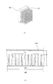
- FIG. 1 It is a block diagram of the heat exchange apparatus 37 with which the refrigerator 501 by Example 1 of the 2nd Embodiment of this invention was equipped. It is a figure which shows schematic structure of the refrigerator 550 by Example 2 of the 2nd Embodiment of this invention. It is a figure explaining the refrigerator 550 by Example 2-1 of the 2nd Embodiment of this invention. It is a figure explaining the refrigerator 550 by Example 2-2 of the 2nd Embodiment of this invention. It is a figure explaining the refrigerator 550 by Example 2-3 of the 2nd Embodiment of this invention. It is a figure explaining the refrigerator by Example 3-1 of the 2nd Embodiment of this invention. It is a figure explaining the refrigerator by Example 3-2 of the 2nd Embodiment of this invention. It is a figure explaining the refrigerator by Example 3-3 of the 2nd Embodiment of this invention. It is a figure explaining the refrigerator by Example 3-4 of the 2nd Embodiment of this invention.
- FIG. 1 is a perspective view showing an appearance of a heat storage container 100 according to the present embodiment.
- a direct cooling refrigerator will be described as an example of the heat storage container 100.
- the heat storage container 100 includes a heat storage container body 101 having a rectangular parallelepiped shape that is vertically high in the installed state.
- FIG. 1 the state which observed the front surface 101a of the thermal storage container main body 101 from diagonally upper left is shown.
- the front surface 101a of the heat storage container main body 101 is provided with rectangular openings at the upper and lower stages.
- a hollow box-shaped refrigeration chamber 104 is provided in the heat storage container body 101 with the lower rectangular opening as the opening end. Further, a hollow box-shaped freezer compartment 105 is provided in the heat storage container main body 101 with the upper rectangular opening as an opening end. The freezer compartment 105 has a volume smaller than that of the refrigerator compartment 104.
- the freezer compartment door 103 is shown in a closed state.
- the freezer compartment door 103 has a rectangular flat plate shape having a region that closes the rectangular opening of the freezer compartment 105 in a closed state.
- a refrigerator door 102 is attached to the right side of the open end of the refrigerator compartment 104 and freezer compartment 105 on the front face 101a through a hinge mechanism (not shown) so as to be opened and closed.
- a state where the refrigerator door 102 is opened is indicated by a solid line
- a state where the refrigerator door 102 is closed is indicated by a two-dot chain line refrigerator door 102a.
- the refrigerator door 102 has a rectangular flat plate shape having a region that closes the rectangular openings of both the refrigerator compartment 104 and the freezer compartment 105 in a closed state.
- a door packing 12 for ensuring the sealing of the refrigerator compartment 104 and the freezer compartment 105 when the door is closed is provided on the opposite side of the refrigerator door 102 to the outer periphery including both the refrigerator compartment 104 and the freezer compartment 105. Has been placed.
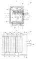
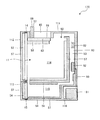
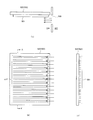
- FIG. 2A shows a state in which a cross section of the heat storage container 100 cut along the AA line of FIG. 1 in the illustrated vertical direction (the direction of the arrow of the AA line) is observed from the right side surface 101b side of the main body. Show. Moreover, in Fig.2 (a), the state which closed the refrigerator door 102 and the freezer compartment door 103 is shown.
- a cooler 2 serving as a heat exchanger is disposed between a refrigerator compartment 104 and a freezer compartment 105 in the heat storage container main body 101.
- the cooler 2 includes a flat plate-like surface member 2a and a back surface member 2b that are opposed to each other with an evaporation mechanism (not shown) for evaporating the refrigerant interposed therebetween.
- the surface member 2 a of the cooler 2 is exposed in the refrigerator compartment 104.
- the back member 2 b of the cooler 2 is exposed in the freezer compartment 105.
- the closed space region 1 is generally composed of at least six inner walls forming a rectangular parallelepiped cavity.
- a surface member 2 a of the cooler 2 is disposed on the inner wall on the upper surface side of the closed space region 1.
- the surface of the surface member 2 a constitutes a part of the inner wall of the closed space region 1.
- the surface of the surface member 2a is exposed to the closed space region 1 and serves as a heat transfer region 10 for transferring heat for controlling the temperature in the closed space region 1.
- the latent heat storage material 3 is partially disposed in the heat transfer region 10.
- Thermal storage refers to a technique for temporarily storing heat and extracting the heat as needed. Examples of the heat storage method include sensible heat storage, latent heat storage, chemical heat storage, and the like.
- latent heat storage is used.
- Latent heat storage uses the latent heat of a substance to store the thermal energy of the phase change of the substance. The heat storage density is high and the output temperature is constant.
- ice (water), paraffin, inorganic salt or the like is used as the latent heat storage material 3.
- the latent heat storage material may be formed by being surrounded by a resin film or a thin plate such as ABS or polycarbonate.
- the latent heat storage material 3 of the present embodiment contains paraffin.
- Paraffin is a generic name for saturated chain hydrocarbons represented by the general formula C n H 2n + 2 .
- the phase change temperature at which the latent heat storage material 3 reversibly changes from a solid phase to a liquid phase is preferably about 4 ° C. to 6 ° C.
- the latent heat storage material 3 includes a gelling agent that gels (solidifies) paraffin.
- a gel refers to a gel that has a three-dimensional network structure formed by cross-linking molecules, and has absorbed and swelled a solvent therein.
- a gelling agent produces a gelling effect only by being contained in paraffin by several weight%.
- the latent heat storage material 3 is attached to the surface of the surface member 2a on the closed space region 1 side, for example, with an adhesive or the like.
- a region where the latent heat storage material 3 is not disposed on the surface of the surface member 2a of the cooler 2 on the side of the closed space region 1 is a heat transfer region exposed portion 6 where the heat transfer region 10 is exposed.
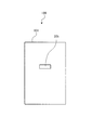
- FIG. 2B shows the shape of the latent heat storage material 3 arranged in the heat transfer region 10 as viewed from the closed space region 1 toward the surface of the surface member 2a.
- the latent heat storage material 3 is affixed to the surface of the surface member 2 a with a predetermined thickness, and a hollow cylindrical through hole 6 a is formed in the heat transfer region exposed portion 6.
- 16 through holes 6a are formed at a predetermined pitch, for example, in 4 rows and 4 columns.
- the total exposed area of the heat transfer region 10 covered with the latent heat storage material 3 is 1, the total exposed area of the heat transfer region 10 exposed at the heat transfer region exposed portion 6 is preferably about 0.8 to 1.2. Further, about 1 is preferable.
- the through-hole 6a does not have to be a hollow cylinder as long as the heat transfer region 10 is exposed.
- the through-hole 6a may have a polygonal column shape such as a hollow triangular column or a quadrangular column, or a tapered shape in which the hollow region expands toward the closed space region 1. It may be.
- the same latent heat storage as the latent heat storage material 3 is also applied to almost the entire inner wall of the refrigerator compartment 104 and the inner wall of the refrigerator door 102 that constitute the inner wall of the closed space region 1 other than the surface member 2 a of the cooler 2. Material 4 is affixed.
- a heat insulating material is disposed between the inner wall and the outer wall of the closed space region 1.
- the heat insulating material 7 is arranged in a region surrounding the refrigerator compartment 104 and the freezer compartment 105 inside the heat storage container main body 101.
- a heat insulating material 8 is disposed inside the refrigerator door 102 (between the outer wall and the latent heat storage material 4). These heat insulating materials 7 and 8 are arranged to insulate the refrigerator compartment 104 and the freezer compartment 105 that are cooled to a predetermined temperature so that heat is not transmitted from the outside of the heat storage container 100.
- the heat insulating materials 7 and 8 are formed using a forming material such as a fiber heat insulating material (glass wool or the like) or a foamed resin heat insulating material.
- a pipe 20 for supplying a refrigerant to an evaporation mechanism (not shown) in the cooler 2 is disposed inside the heat storage container main body 101.
- the pipe 20 is connected to a compressor 21 housed in a compressor housing portion 106 disposed on the bottom surface of the heat storage container main body 101.
- a gas compression type cooling device is configured.
- a gas absorption cooling device or an electronic cooling device using the Peltier effect may be used.
- the refrigerant compressed by the compressor 21 is condensed in the pipe 20 and then expanded to reach the cooler 2.
- the cooler 2 cools the refrigerator compartment 104 and the freezer compartment 105 by heat of vaporization when the expanded refrigerant evaporates.
- the cooling capacity of the cooler 2 is higher on the freezer compartment 105 side than on the heat transfer region 10 on the refrigerator compartment 104 side.
- the temperature in the freezer compartment 105 can be cooled to about ⁇ 10 ° C. and the temperature in the refrigerator compartment 104 can be about 3 ° C.
- heat exchange is performed between the surface member 2 a of the cooler 2 exposed in the closed space region 1 and the air in the closed space region 1.
- a temperature sensor (not shown) is installed at a predetermined position in the closed space region 1.
- the driving of the cooling device is controlled by a temperature control device (not shown) provided in the heat storage container 100 based on the temperature in the closed space region 1 measured by the temperature sensor, and the temperature in the closed space region 1 is adjusted in the heat transfer region 10. Heat transfer is performed for control.
- the latent heat storage material 3 is arranged at a predetermined rate. For this reason, the cooler 2 can directly cool the latent heat storage material 3 and can maintain the latent heat storage material 3 in a solid phase state having a phase transition temperature or lower in a relatively short time. In the region where the latent heat storage material 3 is disposed in the heat transfer region 10, heat exchange between the refrigerant in the cooler 2 and the air in the closed space region 1 is performed indirectly via the latent heat storage material 3.
- the latent heat storage material 3 that maintains the solid state exhibits a function of flattening the temporal change distribution of the temperature in the closed space region 1.
- the latent heat storage material 4 disposed on the inner wall of the closed space region 1 is also in contact with the air in the closed space region 1 and gradually maintained in a solid phase state below the phase transition temperature.
- the latent heat storage material 4 that maintains the solid state also exhibits a function of flattening the temporal change distribution of the temperature in the closed space region 1.
- the latent heat storage material 3 can be directly cooled by the cooler 2, and the latent heat storage material 3 is maintained in a solid phase state below the phase transition temperature in a relatively short time. can do. For this reason, useless power consumption can be suppressed in the heat storage container 100 according to the present embodiment.
- the heat transfer area exposed portions 6 are arranged in the heat transfer area 10 at a predetermined rate. For this reason, the air in the closed space region 1 can be directly cooled by the surface member 2a of the cooler 2 exposed by the heat transfer region exposed portion 6, and the air in the closed space region 1 can be cooled to a desired temperature in a relatively short time. The temperature can be lowered and maintained. Moreover, since the plurality of through holes 6a of the heat transfer region exposed portion 6 are formed at equal intervals, the inside of the closed space region 1 can be uniformly cooled. For this reason, useless power consumption can be suppressed in the heat storage container 100 according to the present embodiment.
- the latent heat storage materials 3 and 4 reversibly undergo a phase transition from a solid phase to a liquid phase at a temperature between a temperature controllable in the closed space region 1 and a temperature of the atmosphere around the closed space region 1 in steady operation.
- normal (linear structure) tetradecane C 14 H 30
- the melting point of normal tetradecane is about 5.9 ° C.
- the volume of the latent heat storage material shrinks during the phase change to the solid phase. After the latent heat storage material 3 has completely changed to a solid phase, the cross-sectional area of the through-hole 6a becomes wide due to volume contraction of the latent heat storage material 3. For this reason, the heat transfer area
- the heat transfer area 10 is disposed on the inner wall of the closed space area 1, the latent heat storage material 3 is disposed in the heat transfer area 10 at a predetermined rate. For this reason, it is possible to achieve a cold insulation effect also in the heat transfer region 10.
- the heat storage container 100 of the present embodiment even if a power supply (not shown) of the heat storage container 100 is turned off due to a power failure or the like, the temperature in the closed space region 1 is kept at a predetermined low temperature for a certain period. Can be maintained.
- the volume of the latent heat storage material expands when the phase changes to the liquid phase.
- the cross-sectional area of the through hole 6a becomes narrow due to the volume expansion of the latent heat storage material 3. For this reason, the exposed area of the heat transfer region 10 can be reduced and the cooling state of the refrigerator compartment 104 can be maintained for a longer time.
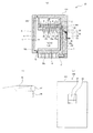
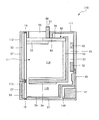
- FIG. 3 shows a heat storage container according to a comparative example.
- FIG. 3A shows the heat storage container 200 according to the first comparative example.
- FIG. 3B shows a heat storage container 210 according to Comparative Example 2.
- 3 (a) and 3 (b) both show the same cross section as the cross section of the heat storage container 100 shown in FIG. 2 (a).
- the same components as those of the heat storage container 100 according to the present embodiment are denoted by the same reference numerals, and the description thereof is omitted.
- the entire surface member 2a of the cooler 2 of the heat storage container 200 of Comparative Example 1 shown in FIG. 3A is covered with the latent heat storage material 4 having no through holes. Accordingly, there is no exposed portion at which the surface member 2a of the cooler 2 can directly contact the air in the refrigerator compartment 104.
- the air in the refrigerating chamber 104 cannot be directly cooled by the surface member 2a of the cooler 2, so that the air in the refrigerating chamber 104 can be lowered to the desired temperature and maintained. Takes a long time. For this reason, in the heat storage container 200 by the comparative example 1, useless electric power consumption will arise.
- the surface member 2a of the cooler 2 is arranged at the upper part of the refrigerating chamber 104, and no latent heat storage material is arranged on the surface member 2a of the cooler 2, the surface member 2a of the cooler 2 is kept cold. The effect cannot be achieved. For this reason, in the heat storage container 210 according to Comparative Example 2, when a power supply (not shown) of the heat storage container 210 is turned off due to a power failure or the like, the time during which the temperature in the refrigerator compartment 104 can be maintained at a low temperature is relatively short. Become.
- the temperature holding ability can be improved while suppressing power consumption.
- Example 2 Next, the heat storage container 110 according to Example 2 of the present embodiment will be described with reference to FIG. About the component which has the same function and effect
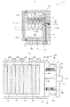
- FIG. 4A shows the heat storage container 110 of the present embodiment in the same cross section as the cross section of the heat storage container 100 shown in FIG.
- the surface member 2a of the cooler 2 of a present Example has uneven
- the concavo-convex shape has a convex portion extending substantially parallel to the front surface 101a of the heat storage container main body 101 and a groove space serving as a concave portion adjacent in a direction orthogonal to the front surface 101a.
- a plurality of sets are arranged side by side in a direction orthogonal to the front surface 101a, with adjacent convex portions and concave portions as a set.
- the cross section shown in FIG. 4A of the uneven shape is a plurality of continuous rectangular waves.
- the latent heat storage material 5 made of the same material as the latent heat storage material 3 of Example 1 is attached with an adhesive or the like to fill the groove space.
- the surface inside the closed space region 1 of the convex portion of the surface member 2a and the surface inside the closed space region 1 of the latent heat storage material 5 are flat with no steps.
- the uneven surface of the surface member 2 a becomes the heat transfer region 10.
- the surface of the convex portion of the surface member 2 a becomes the heat transfer region exposed portion 6.
- the latent heat storage material 5 and the heat transfer region exposed portion 6 are alternately arranged in the heat transfer region 10, and the heat transfer region 10 of the heat transfer region exposed portion 6 is It protrudes inward in the closed space region 1 from the heat transfer region 10 other than the heat transfer region exposed portion 6.
- FIG. 4B shows a shape of the latent heat storage material 5 arranged in the heat transfer region 10 as viewed from the closed space region 1 in the surface direction of the surface member 2a.
- the heat transfer region exposed portion 6 is composed of the surface of a plurality of convex portions of the surface member 2a formed in an elongated rectangular stripe shape.
- the latent heat storage material 5 is attached to the surface member 2a concave surface between adjacent heat transfer region exposed portions 6 in an elongated rectangular stripe shape.
- each latent heat storage material 5 and each heat transfer region exposed portion 6 are formed substantially the same. For this reason, the total covered area of the heat transfer area 10 covered with the latent heat storage material 5 and the total exposed area of the heat transfer area 10 exposed in the heat transfer area exposed portion 6 are approximately 1: 1. Yes.
- the surface of the convex portion of the surface member 2a may be formed so as to fill the through hole 6a in the configuration shown in FIG.
- the latent heat storage material 5 is in direct contact with the bottom surface and both side surfaces of the concave surface of the surface member 2a. For this reason, since the contact area of the surface member 2a and the latent heat storage material 5 can be enlarged compared with the case where it contacts only on the bottom surface like Example 1, the latent heat storage material 5 is cooled in a shorter time. be able to.
- the heat transfer area 10 is arranged on the upper part of the inner wall of the closed space area 1, the latent heat storage material 5 is arranged in the heat transfer area 10 at a predetermined rate. For this reason, it is possible to achieve a cold insulation effect also in the heat transfer region 10.
- the heat storage container 120 of the present embodiment even if a power supply (not shown) of the heat storage container 120 is turned off due to a power failure or the like, the temperature in the closed space region 1 is kept at a predetermined low temperature for a certain period. Can be maintained. Moreover, according to the heat storage container 120, the temperature holding ability can be improved while suppressing power consumption.
- Example 3 Next, the heat storage container 120 according to Example 3 of the present embodiment will be described with reference to FIGS.
- symbol is attached
- FIGS. Fig.5 (a) has shown the thermal storage container 120 of a present Example by the cross section similar to the cross section of the thermal storage container 100 shown to Fig.2 (a).
- the heat transfer region 10 on the surface of the surface member 2a of the cooler 2 of the present embodiment has the same planar shape as that of the first embodiment.
- a plurality of stripe-like latent heat storage materials 5 similar to those in the second embodiment are arranged in the heat transfer region 10.
- a stripe-shaped space region between adjacent latent heat storage materials 5 is a heat transfer region exposed portion 6.
- each latent heat storage material 5 and each heat transfer region exposed portion 6 are formed substantially the same. For this reason, the total covered area of the heat transfer area 10 covered with the latent heat storage material 5 and the total exposed area of the heat transfer area 10 exposed in the heat transfer area exposed portion 6 are approximately 1: 1. Yes.
- Each surface inside the closed space region 1 of the plurality of latent heat storage materials 5 is formed so as to be included in the same plane (hereinafter referred to as a first virtual plane).
- the height of the inner surface of the closed space region 1 of the plurality of latent heat storage materials 5 is formed substantially the same, so the first virtual plane is orthogonal to the front surface 101a of the heat storage container body 101.
- the heat storage container body 101 is almost horizontal in the installed state.
- a linear guide groove 32r (not shown in FIG. 5A) is formed on the inner wall of the right side surface 101b of the main body of the closed space region 1.
- a linear guide groove 32l (not shown in FIG. 5A) is formed on the inner wall of the left side surface of the main body of the closed space region 1.
- the guide grooves 32r and 32l are formed in parallel to each other.
- the guide grooves 32r and 32l are disposed on the second virtual plane parallel to the first virtual plane below the first virtual plane.
- the latent heat storage material support member 30 is slidably supported in the second virtual plane supported by the two parallel guide grooves 32r and 32l.
- the configuration of the latent heat storage material support member 30 will be described using FIG. 5B together with FIG. FIG. 5B shows the vicinity of the first and second virtual planes viewed from the closed space region 1 in the surface direction of the surface member 2a.
- the latent heat storage material support member 30 has an elongated rod-shaped guided member 30r that fits into the guide groove 32r and can slide in the guide groove 32r.
- the latent heat storage material support member 30 has an elongated rod-shaped guided member 30l that is fitted in the guide groove 32l and can slide in the guide groove 32l.
- One end sides of the guided members 30 r and 30 l are fixed to the base material 30 a of the latent heat storage material support member 30.
- a handle 30b is provided on the opposite side of the guided members 30r and 30l with the base material 30a interposed therebetween.
- a heat insulating material 31 formed of the same forming material as the heat insulating material 7 is disposed inside the handle 30b.
- a latent heat storage material fixing portion 30d extending in substantially parallel to the front surface 101a of the heat storage container main body 101 in the installed state is disposed.
- a space 30e is formed adjacent to the latent heat storage material fixing portion 30d in a direction orthogonal to the front surface 101a.
- a plurality of sets are arranged side by side in a direction orthogonal to the front surface 101a, with the adjacent latent heat storage material fixing portion 30d and the space portion 30e as a set.
- a striped latent heat storage material 35 similar to the latent heat storage material 5 is fixed to the latent heat storage material fixing portion 30d.
- the latent heat storage material 35 is used to shield the heat transfer area exposed portion 6 in addition to cooling the inside of the closed space area 1 in the event of a power failure.
- the latent heat storage material support member 30 and the guide grooves 32r and 32l constitute a shielding mechanism 300 that moves the latent heat storage material 35 to the heat transfer region exposure part 6 and shields the heat transfer region exposure part 6.
- each latent heat storage material 35 and each space 30e are formed to be substantially the same as the length and width of the stripes of each latent heat storage material 5 and each heat transfer region exposed portion 6.
- the latent heat storage material 35 is positioned so as to overlap vertically below the latent heat storage material 5.
- the space 30e is positioned so as to overlap vertically below the heat transfer region exposed portion 6. In this state, the heat transfer region exposed portion 6 is exposed to the closed space region 1 through the space 30e.
- FIG. 6 shows a state where the heat transfer region exposed portion 6 is shielded by the shielding mechanism 300.
- Fig.6 (a) has shown the thermal storage container 120 of a present Example by the cross section similar to the cross section shown to Fig.5 (a).
- FIG. 6B shows the vicinity of the first and second virtual planes viewed from the closed space region 1 in the surface direction of the surface member 2a.
- the latent heat storage material 35 is positioned so as to overlap vertically below the heat transfer region exposed portion 6. Further, the space 30 e is positioned so as to overlap vertically below the latent heat storage material 5. In this state, the heat transfer region exposed portion 6 is shielded from the closed space region 1 by the latent heat storage material 35.
- FIG. 7 shows the heat storage container 120 as viewed from the back side.
- the handle 30 b is exposed to the outside of the heat storage container 120. For this reason, the handle 30b can be moved in the horizontal direction by the operator.
- the operation of the heat storage container 120 will be described.
- the latent heat storage material support member 30 of the shielding mechanism 300 slides in the direction of the front surface 101a. Accordingly, the latent heat storage material 35 of the latent heat storage material support member 30 moves vertically below the latent heat storage material 5. Therefore, as shown in FIG. 5, the heat transfer region exposed portion 6 is exposed to the closed space region 1 through the space 30e.
- the air in the closed space region 1 can be directly cooled by the surface member 2a of the cooler 2 exposed by the heat transfer region exposed portion 6, and the air in the closed space region 1 can be cooled to a desired temperature in a relatively short time.
- the temperature can be lowered and maintained.
- the plurality of heat transfer region exposed portions 6 are formed at equal intervals, the inside of the closed space region 1 can be uniformly cooled. For this reason, useless power consumption can be suppressed in the heat storage container 120 according to the present embodiment.
- the latent heat storage material support member 30 of the shielding mechanism 300 slides in the opposite direction to the front surface 101a.
- the latent heat storage material 35 of the latent heat storage material support member 30 moves vertically below the heat transfer region exposed portion 6. Therefore, as shown in FIG. 6, the heat transfer region exposed portion 6 is shielded from the closed space region 1 by the latent heat storage material 35.
- the heat transfer region exposure unit 6 is moved by the latent heat storage material 35. Can be shielded. For this reason, a cold insulation effect can be produced on the entire surface of the heat transfer region 10.
- the temperature in the closed space region 1 is kept at a predetermined low temperature for a certain period. Can be maintained.
- the heat storage container 120 is provided with the shielding mechanism 300, so that the heat transfer region exposed portion 6 can be switched between the exposed state and the shielded state with respect to the closed space region 1. Moreover, according to the heat storage container 120 according to the present embodiment, the temperature holding ability can be improved while suppressing power consumption.
- a handle 33, a metal plate 36, and a pulley 37 are used as members for sliding the latent heat storage material support member 30 of the shielding mechanism 300.
- FIG. 8A shows a heat storage container 130 of this modification in a cross section similar to the cross section shown in FIG.
- FIG. 8A shows a state where the heat transfer region exposed portion 6 is shielded from the closed space region 1 by the latent heat storage material 35.
- FIG. 8B shows the vicinity of the pulley 37.
- FIG.8 (c) has shown the state which looked at the thermal storage container 130 from the back surface side.
- the handle 33, the metal plate 36, and the pulley 37 will be described with reference to FIGS. 8 (a), 8 (b), and 8 (c).
- a metal plate 36 is attached to the base material 30a (not shown in FIG. 8A) of the latent heat storage material support member 30. As shown in FIGS.
- the metal plate 36 is guided by a guide groove (not shown). One end of the metal plate 36 can move in the horizontal direction, and the other end can move in the vertical direction via a pulley 37.
- a handle 33 is attached to the other end of the metal plate 36. As shown in FIGS. 8A and 8C, the handle 33 is disposed in the opening 34 formed on the back side of the heat storage container 130. One end of the handle 33 protrudes from the opening 34. For this reason, the handle 33 can be held by the operator and moved in the vertical direction.
- the metal plate 36 is made of a metal having a small rigidity. For this reason, the region of the metal plate 36 in contact with the pulley 37 is deformed along the circumference of the pulley 36.
- the latent heat storage material support member 30 of the shielding mechanism 300 slides in the direction of the front surface 101a via the metal plate 36.
- the latent heat storage material 35 of the latent heat storage material support member 30 moves vertically below the latent heat storage material 5. Therefore, the heat transfer area exposed portion 6 is exposed to the closed space area 1 through the space 30e.
- the latent heat storage material support member 30 of the shielding mechanism 300 slides in the opposite direction to the front surface 101a.
- the latent heat storage material 35 of the latent heat storage material support member 30 moves vertically below the heat transfer region exposed portion 6. Therefore, as shown in FIG. 8A, the heat transfer region exposed portion 6 is shielded from the closed space region 1 by the latent heat storage material 35.
- Example 4 Next, the heat storage container 140 according to Example 4 of the present embodiment will be described with reference to FIGS. 9 and 10.
- symbol is attached
- FIG. 9A shows a heat storage container 140 according to this embodiment in the same cross section as the cross section shown in FIG.
- FIG. 9B shows the vicinity of the first and second virtual planes as viewed from the closed space region 1 in the surface direction of the surface member 2a.
- 9A and 9B show a state where the heat transfer region exposed portion 6 is exposed to the closed space region 1 through the space portion 30e.
- the surface member 2a of the cooler 2 of this embodiment has an uneven shape, as in the second embodiment shown in FIG.
- the latent heat storage material 5 is affixed with the adhesive etc. in the uneven
- FIG. 10A shows a heat storage container 140 according to the present embodiment in a cross section similar to the cross section shown in FIG.
- FIG. 10B shows the vicinity of the first and second virtual planes viewed from the closed space region 1 in the surface direction of the surface member 2a.
- FIGS. 10A and 10B both show a state where the heat transfer region exposed portion 6 is shielded from the closed space region 1 by the latent heat storage material 35.
- the surface member 2a of the cooler 2 has an uneven shape, and the latent heat storage material 5 is disposed in the uneven portion of the surface member 2a. For this reason, there can exist an effect similar to the thermal storage container 110 by Example 2.
- the heat storage container 140 includes a shielding mechanism 300 that shields the heat transfer region exposed portion 6. For this reason, the effect similar to the thermal storage container 120 and 130 by Example 3 can be show
- Example 5 Next, the heat storage container 150 according to Example 5 of the present embodiment will be described with reference to FIGS. 11 and 12.
- symbol is attached
- FIG. 11A shows a heat storage container 150 according to this embodiment in a cross section similar to the cross section shown in FIG. FIG. 11B shows the vicinity of the first and second virtual planes as viewed in the surface direction of the surface member 2a.
- an elongated rod-like base material 40 is disposed so as to face the base material 30 a of the latent heat storage material support member 30.
- the base material 40 is fixed to the inner wall of the heat storage container main body 101.
- An electric motor 41 is fixed substantially at the center of the substrate 40. Electric power is supplied to the electric motor 41 by a power source (not shown) of the heat storage container 150.
- a rope winder (not shown) is attached to the rotating shaft of the electric motor 41.
- One end of a rope 42 is fixed to the rope winder.
- the other end of the rope 42 is fixed to the base material 30 a of the latent heat storage material support member 30.
- the rope 42 has a required length.
- One ends of compression coil springs 43 r and 43 l are attached to both sides of the base material 40 on the latent heat storage material support member 30 side with the rope 42 interposed therebetween.
- the other ends of the compression coil springs 43r and 43l are attached to the base material 30a.
- positioning members 44r and 44l are attached to the base material 40 on the outside of the compression coil springs 43r and 43l with the rope 42 interposed therebetween. At the tip of the positioning members 44r and 44l, a contact surface is provided that contacts the end of the base material 30a of the latent heat storage material support member 30 drawn by winding the rope 42 with the electric motor 41. In the state shown in FIG.
- the contact surfaces of the positioning members 44 r and 44 l are in contact with the end of the base material 30 a of the latent heat storage material support member 30. Further, in the state shown in FIG. 11B, the compression coil springs 43r and 43l are compressed.
- the electric motor 41 is driven and the rope 42 is wound up. Therefore, the latent heat storage material support member 30 is drawn toward the base material 40 side. Further, the end portion of the base material 30a of the latent heat storage material support member 30 is in contact with the contact surfaces of the positioning members 44r and 44l. In this state, the latent heat storage material 35 of the latent heat storage material support member 30 is positioned vertically below the latent heat storage material 5. Accordingly, as shown in FIGS. 11A and 11B, the heat transfer region exposed portion 6 is exposed to the closed space region 1 through the space 30e.
- FIG. 12A shows a heat storage container 150 according to the present embodiment in a cross section similar to the cross section shown in FIG.
- FIG. 12B shows the vicinity of the first and second virtual planes as viewed from the inside of the closed space region 1 in the surface direction of the surface member 2a.
- FIGS. 12A and 12B show a case where the electric motor 41 is in a non-driven state.
- the extension force of the compression coil springs 43r and 43l is won, and the rope take-up device of the electric motor 41 is reversely rotated and the rope 42 is extended.
- the extension force of the compression coil springs 43 r and 43 l acts on the latent heat storage material support member 30, and the latent heat storage material support member 30 moves a predetermined distance in a direction away from the base material 40.
- the spring lengths of the compression coil springs 43r and 43l are longer than those shown in FIG.
- the latent heat storage material 35 of the latent heat storage material support member 30 is positioned vertically below the heat transfer region exposed portion 6. Accordingly, as shown in FIGS. 12A and 12B, the heat transfer region exposed portion 6 is shielded from the closed space region 1 by the latent heat storage material 35.
- the temperature can be lowered and maintained. Moreover, since the plurality of heat transfer region exposed portions 6 are formed at equal intervals, the inside of the closed space region 1 can be uniformly cooled. For this reason, wasteful power consumption can be suppressed in the heat storage container 150 according to the present embodiment.
- the latent heat storage material 35 can be moved vertically below the heat transfer region exposed portion 6 by the shielding mechanism 300.
- the exposed part 6 can be shielded.
- the cooling effect can be exerted also on the entire surface of the heat transfer region 10.
- Example 6 the heat storage container 160 according to Example 6 of the present embodiment will be described with reference to FIGS. 13 and 14. Constituent elements having the same functions and operations as those of the heat storage containers according to the first to fifth embodiments are denoted by the same reference numerals and description thereof is omitted.
- FIG. 13A and FIG. 14A show a cross section of the heat storage container 160 according to this embodiment.
- FIG. 13A and FIG. 14A show a cross section similar to the cross section of the heat storage container 100 shown in FIG. FIG. 13B and FIG. 14B show the vicinity of the first and second virtual planes as viewed from the inside of the closed space region 1 in the surface direction of the surface member 2a.
- FIGS. 13A and 13B show a state in which the heat transfer region exposed portion 6 is exposed to the closed space region 1 through the space 30e.
- 14A and 14B show a state in which the heat transfer region exposed portion 6 is shielded from the closed space region 1 by the latent heat storage material 35.
- FIG. 13A and FIG. 14A show a cross section similar to the cross section of the heat storage container 100 shown in FIG. FIG. 13B and FIG. 14B show the vicinity of the first and second virtual planes as viewed from the inside of the closed space region 1 in the surface direction of the surface member 2a.
- the heat storage container 160 has substantially the same configuration as the heat storage container 120 according to the third embodiment, but is different in that it includes a water tray 48.
- the water tray 48 is mounted on a water tray mounting portion (not shown) disposed below the cooler 2.
- the water tray 48 can be taken out from the closed space region 1 by opening the refrigerator door 102 of the heat storage container 160.
- a plurality of striped latent heat storage materials 5 are attached to the lower part of the water receiving tray mounting portion.
- a stripe-shaped space region between adjacent latent heat storage materials 5 is a heat transfer region exposed portion 6.
- the latent heat storage material 5 may be attached to a predetermined position below the water receiving tray 48.
- frost adheres to the surface member 2a of the cooler 2 when a predetermined period of time elapses during steady operation.
- the water receiving tray 48 is arranged to receive water generated by frost melting when the surface member 2a is defrosted. Since water generated at the time of defrosting is accumulated in the water receiving tray 48, the water receiving tray 48 can be taken out of the heat storage container 160 and the accumulated water can be discarded.
- FIG. 15 shows a schematic cross-sectional configuration of the heat storage container 170 according to this embodiment.
- a fan refrigerator will be described as an example of the heat storage container 170.
- the heat storage container 170 has a rectangular parallelepiped heat storage container main body 111.
- the heat storage container main body 111 is provided with rectangular openings at the upper and lower stages.
- a hollow box-shaped refrigerator compartment 114 is provided in the heat storage container main body 111 with the upper rectangular opening as an opening end.
- a hollow box-like vegetable chamber 115 is provided in the heat storage container main body 111 with the lower rectangular opening as an opening end.
- the vegetable compartment 115 has a volume smaller than that of the refrigerator compartment 114.
- a refrigerator door 112 is attached to the open end of the refrigerating chamber 114 of the heat storage container body 111 through a hinge mechanism (not shown) so as to be opened and closed.
- the refrigerator door 112 is in a closed state.
- the refrigerator door 112 has a rectangular flat plate shape having a region that closes the rectangular opening of the refrigerator compartment 114 in a closed state.
- a door packing 14 is provided on the opposite side of the refrigerator door 112 to the outer periphery of the refrigerator compartment 114 opening to ensure the sealing of the refrigerator compartment 114 when the door is closed.
- the vegetable compartment door 113 is attached to the open end of the vegetable compartment 115 of the heat storage container main body 111 through a hinge mechanism (not shown) so that it can be opened and closed.
- the vegetable compartment door 113 has shown the closed state.
- the vegetable compartment door 113 has a rectangular flat plate shape with a region that closes the rectangular opening of the vegetable compartment 115 in a closed state.
- the door packing 15 for ensuring the airtightness of the vegetable compartment 115 at the time of door closing is arrange
- the vegetable compartment 115 may have a drawer-type configuration in which the vegetable compartment can be pulled out instead of opening and closing the door.
- the closed space region 11 is composed of at least six inner walls that form a substantially rectangular parallelepiped cavity.
- a heat transfer region 60 that moves heat for controlling the temperature in the closed space region 11 is disposed.
- the heat transfer region 60 is an opening surface of the inner wall of the closed space region 11.
- the same latent heat storage material 53 as the latent heat storage material 3 of the first embodiment is attached to almost the entire inner wall of the refrigerator compartment 114 other than the heat transfer region 60 and the inner wall of the refrigerator door 112.
- a latent heat storage material 54 having a phase transition temperature higher than that of the latent heat storage material 3 is attached to almost the entire inner wall of the vegetable room 115 and the inner wall of the vegetable room door 113.
- the phase transition temperature at which the latent heat storage material 54 reversibly changes from a solid phase to a liquid phase is preferably about 7 to 9 ° C.
- a latent heat storage material 63 for shielding the heat transfer region 60 is disposed outside the closed space region 11 and inside the heat storage container main body 111.
- the latent heat storage material 63 is formed of the same forming material as the latent heat storage material 53.
- the latent heat storage material 63 has a thin plate shape larger than the heat transfer region 60.
- the latent heat storage material 63 is attached to a latent heat storage material support member 68.
- the latent heat storage material support member 68 is supported by a guide groove (not shown) so as to slide in a substantially horizontal direction when the heat storage container main body 101 is installed.
- An opening 65 is disposed in the heat storage container main body 111 above the latent heat storage material 63, and a handle 66 is attached to the latent heat storage material support member 68 in the opening 65.
- the head of the handle 66 protrudes from the opening 65. For this reason, the handle 66 can be moved in the horizontal direction by the operator holding it with the hand.
- the latent heat storage material support member 68 and the guide groove (not shown), the opening 65, and the handle 66 constitute a shielding mechanism 310 that moves the shielding latent heat storage material 63 to the heat transfer area 60 and shields the heat transfer area 60. is doing.
- a heat insulating material 57 is disposed between the inner wall and the outer wall of the closed space region 11. Specifically, a heat insulating material 57 is provided on the inner side of the heat storage container body 111 so as to surround the closed space region 11 and the vegetable compartment 115, on the outer side of the closed space region 11, and on the inner side of the refrigerator door 112 and the vegetable compartment door 113. Is arranged. A heat insulating material 57 is also arranged inside the handle 66. The heat insulating material 57 is disposed to insulate the closed space region 11 and the vegetable compartment 115 that are cooled to a predetermined temperature so that heat is not transmitted from the outside of the heat storage container 170.
- a cooler 52 is arranged in a duct 83 outside the closed space region 11 and the vegetable compartment 115 and inside the heat storage container body 111.
- a pipe 80 for supplying a refrigerant to an evaporation mechanism (not shown) in the cooler 52 is disposed inside the heat storage container main body 111.
- the pipe 80 is connected to a compressor 81 housed in a compressor housing portion 116 disposed on the bottom surface of the heat storage container main body 111.
- a gas compression type cooling device is configured.
- a fan 82 is disposed above the cooler 52 to blow cool air having a predetermined temperature from the cooler 52 to the heat transfer region 60 and circulate it in the heat storage container 170.
- FIG. 16 shows a schematic cross-sectional configuration of the heat storage container 170 according to this embodiment.
- the heat transfer region 60 is shown shielded from the closed space region 11 by the latent heat storage material 63.
- the operation of the heat storage container 170 will be described.
- the power supply (not shown) of the heat storage container 170 is on, the refrigerant compressed by the compressor 81 is condensed in the pipe 20 and then expanded to reach the cooler 52.
- the cooler 52 cools the heat storage container 111 with heat of vaporization when the expanded refrigerant evaporates.
- the cool air that has exited the cooler 52 rises in the duct 83 of the heat storage container body 111 by the fan, and is blown from the heat transfer area 60 exposed to the closed space area 11 on one end side of the duct 83 to the closed space area 11.
- a temperature sensor (not shown) is installed at a predetermined position in the closed space region 11.
- the driving of the cooling device is controlled by a temperature control device (not shown) provided in the heat storage container 170 based on the temperature in the closed space region 11 measured by the temperature sensor, and heat for controlling the temperature in the closed space region 11. A move is made.
- the latent heat storage material 53 in the closed space region 11 and the latent heat storage material 63 outside the closed space region are cooled by the cold air that has exited the cooler 52. Therefore, the latent heat storage materials 53 and 63 can be maintained in a solid phase state below the phase transition temperature.
- the latent heat storage materials 53 and 63 that maintain the solid state exhibit a function of flattening the temporal change distribution of the temperature in the closed space region 11.
- a vent pipe is disposed between the closed space region 11 and the vegetable compartment 115.
- the cold air that has cooled the inside of the closed space region 11 reaches the vegetable compartment 115 through the vent pipe.
- the inside of the vegetable compartment 115 and the latent heat storage material 54 are cooled by the cold air that has reached the vegetable compartment 115.
- the cooled latent heat storage material 54 is maintained in a solid phase state below the phase transition temperature.
- the latent heat storage material 54 that maintains the solid state also exhibits the function of flattening the temporal change distribution of the temperature in the vegetable compartment 115.
- the cold air after cooling the closed space region 11 circulates in the vegetable compartment. For this reason, the temperature in the vegetable compartment 115 becomes higher than the temperature in the closed space region 11.
- the set temperature of the vegetable compartment 115 is a temperature suitable for storing vegetables, and is, for example, about 6 ° C to 8 ° C. Further, the set temperature of the closed space region 11 is lower than the set temperature in the vegetable compartment 115 and is, for example, about 3 ° C.
- the temperature distribution in the heat storage container 170 can be kept more uniform than in a direct cooling refrigerator.
- a vent pipe is disposed between the vegetable room 115 and the other end of the duct 83 where the cooler 52 is disposed.
- the air cooled in the vegetable compartment 115 is exhausted to the other end of the duct outside the vegetable compartment 115 through the vent pipe.
- the exhausted air returns to the cooler 52 in the duct 83.
- air is circulated in this way.
- the latent heat storage material 63 is moved to the heat transfer region 60 to shield the heat transfer region from the closed space region 11. Then, the cold insulation by the latent heat storage materials 53 and 65 is started in the closed space region 11.
- the air in the closed space region 11 is maintained in a predetermined temperature range for a certain period by the latent heat storage material 53 stretched around the inner wall of the closed space region 11 and the latent heat storage material 63 that shields the heat transfer region 60. More specifically, the temperature in the closed space region 11 is maintained at about 6 ° C. during the period until the latent heat storage materials 53 and 65 undergo a phase transition from the solid phase to the liquid phase.
- a plurality of through holes may be formed in the latent heat storage material 63 for shielding the heat transfer region 60.
- the heat transfer region 60 is divided into a region shielded by the latent heat storage material 63 and a region where the through hole of the latent heat storage material 63 is formed and the heat transfer region 60 is exposed. Therefore, when the heat storage container 170 is in a steady operation, the cool air is blown into the closed space region 11 through the through hole in which the heat transfer region 60 is exposed.
- the heat storage container 170 has been described as an example of a fan-type refrigerator having a refrigerator compartment 114 and a vegetable compartment 115, it can also be applied to a refrigerator having a freezer.
- a latent heat storage material is installed to shield the heat transfer area that controls the temperature in the freezer compartment.
- the latent heat storage material for shielding the heat transfer region exposed portion 6 and the like is attached to the latent heat storage material support member and slidable, but the present embodiment is not limited to this.
- the latent heat storage material is stored in a predetermined storage location such as a refrigerator.
- the latent heat storage material is taken out from the predetermined storage location and attached to the heat transfer area in order to shield the heat transfer area exposed part etc. Good.
- a refrigerator is used as a heat storage container, but this embodiment is not limited to this, and of course can be applied to a warm storage room using a latent heat storage material having a phase transition temperature of, for example, several tens of degrees Celsius. It is.
- the second embodiment according to the present invention relates to a heat storage using a latent heat storage material.
- Refrigerator refrigerators are known to be fan type or direct cooling type.
- domestic refrigerator-freezers are mainly fan-type.
- the refrigerator-freezer using the heat storage material and the cool storage agent is known (patent document 6, patent document 7).
- Patent Document 6 discloses a heat storage refrigerator in which a heat storage material having a phase change temperature is provided in a temperature range of a freezing room in a room surrounded by a heat insulating material, and the heat storage material is solidified by circulating cold air in a freezer at night or the like. ing.
- the said heat storage refrigerator can reduce the load of the compressor at the time of cold storage.
- the heat storage refrigerator is provided with a heat storage material in a room covered with a heat insulating material independent of the refrigerator and the freezer, there is a problem that the internal volume is reduced.
- the said thermal storage refrigerator installs a thermal storage material as a block, it has the problem that heat exchange requires time.
- the fan-type refrigerator disclosed in Patent Documents 6 and 7 cools the inside of the refrigerator by circulating cold air.
- the flow of the cold air is set so that the stored food is not dried by the direct cold air.
- Even when a heat storage material is used in a conventional fan-type refrigerator there is a problem that the heat storage material is not efficiently cooled.
- fan-type refrigerator-freezers have a lower cooling rate than direct-cooled refrigerator-freezers. For this reason, the fan type refrigerator-freezer has a problem that it takes time to store cold in the latent heat storage material when the latent heat storage material is installed.
- An object of the present embodiment is to provide a heat storage that can efficiently cool the latent heat storage material.
- the purpose is to generate a heat exchange device that generates air having a temperature different from the ambient temperature, to generate a wind by forcibly convection the air having a different temperature, and to blow the wind, and so that the wind directly hits, Or it is arrange
- the heat insulation box according to the present embodiment further includes a storage room for storing a stored product, and the latent heat storage material is disposed in the storage room.
- the heat insulation box according to the present embodiment further comprising a shelf provided in the storage chamber on which the stored item is placed, and the latent heat storage material is provided in the shelf.
- the heat insulation box according to the present embodiment further including a wind outlet provided in the storage chamber and allowing the wind to flow into the storage chamber, and the latent heat storage material is configured such that the wind flowing out from the wind outlet is directly It is arrange
- the shelf portion includes a wind guide portion that guides the wind to the lower side of the shelf portion.
- the wind guide portion is characterized in that the wind inflow portion is formed wider than the wind outflow portion.
- the heat insulation box according to the present embodiment which is provided in the storage chamber, and is provided at the wind outlet and flows in a predetermined direction in the storage chamber, and is provided in the wind outlet and in a direction different from the predetermined direction. It further has a wind direction switching unit that switches the wind direction of the wind, and the latent heat storage material is arranged in the different direction when viewed from the wind outlet.
- the wind direction switching unit switches the wind direction to the different direction when the latent heat storage material is cooled.
- the shelf portion has a wind guide reflection portion that guides the wind below the shelf portion and reflects the wind.
- the heat insulation box according to the present embodiment wherein the latent heat storage material is detachable.
- the latent heat storage material includes a heat conductive sheet that conducts the heat of the wind.
- the heat insulation box of the present embodiment further comprising a conduction path for conducting the heat of the wind to the heat conduction sheet.
- the latent heat storage material has fins that conduct the heat of the wind.
- the heat insulation box according to the present embodiment wherein the heat conductive sheet can be detached.
- the fin can be detached.
- the latent heat storage material has a thermally conductive filler dispersion portion that conducts heat of the wind.
- the latent heat storage material has irregularities on the surface to which the wind hits.
- the latent heat storage material is normal paraffin.
- the heat insulation box according to the present embodiment wherein the normal paraffin is a gel.
- the heat exchange device includes a cooler that generates cool air having a temperature lower than the ambient temperature.
- the latent heat storage material can be efficiently cooled.
- it demonstrates more concretely using an Example.
- Example 1 The heat storage by Example 1 of this embodiment is demonstrated using FIG.17 and FIG.18.
- the heat storage according to the present embodiment is used for storing stored items at a temperature different from the ambient temperature (room temperature) during steady operation, and examples thereof include a refrigerator, a freezer, and a warm storage.
- the heat insulating box is a fan-type refrigerator.
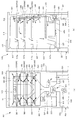
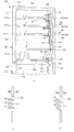
- FIG. 17 is a diagram illustrating a main part of a schematic configuration of a fan-type refrigerator 501 according to the present embodiment.
- FIG. 17A shows a front view of the refrigerator 501 seen through the door 517
- FIG. 17B shows a right side view of the refrigerator 501 seen through the right wall 505.
- FIG. 17A shows a front view of the refrigerator 501 seen through the door 517
- FIG. 17B shows a right side view of the refrigerator 501 seen through the right wall 505.
- FIG. 17A shows a front view of the refrigerator 501 seen through the door 517
- FIG. 17B shows a right side view of the refrigerator
- FIG. 17A shows a damper 533 that cannot be visually recognized in the refrigerator compartment 502 and a blower 506 that cannot be visually recognized in the freezer compartment 508.
- the refrigerator 501 has a rectangular parallelepiped shape as a whole.
- the refrigerator 501 is divided into three regions: a refrigerator compartment 502 provided in the upper stage, a freezer compartment 508 provided in the middle stage, and a vegetable room (not shown) provided in the lower stage.
- the set temperatures of the refrigerator compartment 502, the freezer compartment 508, and the vegetable compartment are set in advance so as to decrease in the order of the vegetable compartment, the refrigerator compartment 502, and the freezer compartment 508. That is, in the refrigerator 501, the set temperature in each storage room is set in advance so that “freezer room 508 ⁇ refrigeration room 502 ⁇ vegetable room”.
- the set temperature in the vegetable room is a temperature suitable for storing vegetables, for example, about 6 ° C to 8 ° C. Further, the set temperature in the refrigerator compartment 502 is lower than the set temperature in the vegetable compartment, for example, about 2 to 5 ° C. The set temperature in the freezer compartment 508 is lower than that of the refrigerator compartment 502 and is, for example, about ⁇ 18 ° C.
- the refrigerator compartment 502 has a thin plate-shaped door 517 that is rotatably provided on the container main body 514 via a hinge (not shown).
- the container main body 514 in the refrigerator compartment 502 has a rectangular opening 516, walls 505 and a partition 525 that are opened by the opening 516 and form a box shape, and a storage chamber 504 that stores stored items. ing.
- the refrigerator compartment 502 and the freezer compartment 508 are partitioned by a partition portion 525.
- the storage chamber 504 is connected to the outside through the opening 516 when the door 517 is opened.
- the storage chamber 504 is a space provided inside the wall portion 505.
- the storage chamber 504 becomes a sealed space surrounded by the door portion 517 and the wall portion 505 when the door portion 517 is closed. Thereby, the refrigerator compartment 502 can maintain the inside of the store room 504 at preset temperature.
- a plurality of latent heat storage materials 503 that store or release thermal energy by phase change are arranged. Although details will be described later, the plurality of latent heat storage materials 503 are arranged at locations where the cold air flowing out from the cold air outlet (wind outlet) 509 provided in the storage chamber 504 directly hits. The plurality of latent heat storage materials 503 are attached to the inner wall side surface of the storage chamber 504.
- the latent heat storage material 503 has a temperature at which the phase change between the solid phase and the liquid phase occurs reversibly within the operating temperature range of the refrigerator compartment 502.
- the latent heat storage material 503 becomes a liquid phase at a temperature higher than the phase change temperature, and becomes a solid phase at a temperature lower than the phase change temperature.
- the latent heat storage material 503 in the present embodiment includes paraffin.
- paraffin As the latent heat storage material 503, a single substance or a mixture of normal (linear structure) paraffin (general formula is C n H 2n + 2 ) and a carbon number n of 10 or more is used.
- the melting point of paraffin varies depending on the number of carbons n.
- n-tetradecane molecular formula: C 14 H 30
- the melting point (5.9 ° C.) of n-tetradecane is included in the operating temperature range of the refrigerator compartment 502.
- the boiling point of n-tetradecane is about 250 ° C. Paraffin becomes a translucent or white soft insoluble solid (wax) at room temperature when the carbon number exceeds a predetermined number.
- the latent heat storage material 503 contains a gelling agent that gels (solidifies) paraffin.
- a gel (chemical gel) refers to a gel that is formed by forming a three-dimensional network structure by cross-linking molecules, and absorbing the solvent therein to swell. Gels are chemically stable as long as they do not break the structure.
- a gelling agent produces a gelling effect only by containing it in paraffin by several weight%.
- the gelling agent used in this example contains a polymer material.
- polyethylene is used as the polymer material.
- the latent heat storage material 503 in the present embodiment is polyethylene-containing paraffin gelled with polyethylene.
- Polyethylene-containing paraffin maintains a solid state as a whole even when the paraffin changes between a solid phase and a liquid phase, and has no fluidity. Accordingly, the polyethylene-containing paraffin does not have fluidity at least within the use temperature range of the latent heat storage material 503.
- the gel-like latent heat storage material 503 can maintain a solid state as a whole before and after the phase change. Thereby, the latent heat storage material 503 can be continuously disposed in the storage chamber 504 before and after the phase change.
- a latent heat storage material stores thermal energy exchanged with the outside during phase transition of a substance as latent heat for phase change.
- the heat of fusion at the melting point of the latent heat storage material is used.
- heat exchange is continuously performed with the outside at a constant temperature, so that temperature change can be suppressed for a relatively long time.
- the storage chamber 504 is provided with a plurality of shelves 523 (four in this example) on which stored items such as food are placed.
- the plurality of shelves 523 have a thin plate shape and are arranged with a predetermined gap.
- a chilled chamber 529 is provided below the storage chamber 504.
- the chilled chamber 529 stores a chilled storage portion 529a that can be pulled out when the door portion 517 is opened.
- the refrigerator 501 has an internal temperature sensor 511 provided on the back of the inner wall of the storage chamber 504.
- the internal temperature sensor 511 is provided for measuring the temperature in the storage chamber 504.
- the refrigerator 501 has a temperature adjustment unit 515 provided on the back of the inner wall of the storage chamber 504.
- the temperature adjustment unit 515 is used by the user to adjust the temperature in the storage chamber 504 to an arbitrary temperature within the range of 2 to 5 ° C.
- the refrigerator 501 has an interior lamp 513 provided on the back of the inner wall of the storage room. The interior lamp 513 is turned off when the door portion 517 is closed, and is turned on when the door portion 517 is opened.
- the door portion 517 is semi-fixed by a door semi-fixing portion 519 provided on the container body 514.
- the door half fixing part 519 has a thin plate shape.
- the door half fixing portion 519 fixes the door portion 517 to the container main body 514 unless the user applies a pulling force to the door portion 517 in order to open the door portion 517.
- the door portion 517 includes door storage portions 517a to 517d arranged in the storage chamber 504 when the door portion 517 is closed.
- the door storage portions 517a to 517d can store, for example, eggs and drinking water.
- the freezer compartment 512 has a thin plate-shaped door 520 that is rotatably provided on the container main body 514 via a hinge (not shown).
- the container body 514 in the freezer compartment 512 has a rectangular opening 518, a wall 505, a partition 525, a freezer compartment 508, and a vegetable room (not shown) (not shown) that are opened by the opening 518 to form a box shape.
- the storage chamber 510 is provided with a latent heat storage material (not shown).
- the storage chamber 510 is connected to the outside through the opening 518 when the door 520 is opened.
- the storage chamber 510 is a space provided inside the wall portion 505.
- the storage chamber 510 becomes a sealed space surrounded by the door portion 520 and the wall portion 505 when the door portion 520 is closed.
- the freezer compartment 508 can maintain the interior of the storage compartment 510 at a set temperature.
- a heat insulating material is provided inside the partition portion that partitions the wall portion 505, the door portions 517 and 520, the partition portion 525, the freezer compartment 508, and the vegetable compartment.
- the heat insulating material insulates the storage chambers 502 and 508 and the latent heat storage material 503 that are cooled during the steady operation of the refrigerator 501 so that heat from the outside is not transmitted through the wall portion 505, the door portions 517 and 520, and the like. It is provided for.
- the heat insulating material can be formed using a material such as a fiber heat insulating material such as glass wool, a foamed resin heat insulating material such as polyurethane foam, or a natural fiber heat insulating material such as cellulose fiber.
- the refrigerator 501 is disposed above the freezer compartment 512 as viewed from the door portion 520 side, and is generated at a heat exchange device 537 (not shown in FIGS. 17A and 17B) and has a temperature different from the ambient temperature. It has a blower 506 that forcibly convects the air and generates wind (for example, cold wind) and blows air. The blower 506 blows the cold air to the storage room 504 of the refrigerating room 502 through the cold air inlet 527.
- the numerical range of the temperature of the cold air is determined by the outside air temperature of the refrigerator 501 and the temperature setting in the refrigerator.
- FIG. 18 is a block diagram illustrating a schematic configuration of a heat exchange device 537 provided in the refrigerator 501.
- the heat exchanging device 537 is disposed below the blower 506 and in the container main body 514. As shown in FIG. 18, the heat exchange device 537 is provided at the bottom of the container main body 514, and compresses the refrigerant 539, and is connected to the compressor 539 and compressed by the compressor 539.
- a condenser 541 that condenses while liquefying
- an expansion valve 543 that is connected to the condenser 541 and expands by reducing the pressure so that the liquefied refrigerant is easily vaporized, and is provided in the vicinity of the blower 506 connected to the expansion valve 543.
- a cooler 545 that cools the surroundings by heat of vaporization when the liquefied refrigerant evaporates.
- the cooler 545 generates cool air having a temperature lower than the ambient temperature. Note that the refrigerant evaporated by the cooler 545 is returned to the compressor 539 to be compressed again.
- the compressor 539 and the condenser 541, the condenser 541 and the expansion valve 543, the expansion valve 543 and the cooler 545, and the cooler 545 and the compressor 539 are connected to each other through predetermined pipes.
- the heat exchange device 537 may include a generally known configuration such as a dryer for removing moisture in the refrigerant.
- the refrigerator 501 has a cold air passage portion 507 connected to the cold air inlet 527 via the damper 533.
- the cold air path portion 507 is provided between the storage chamber 504 and the wall portion 505.
- the cold air path portion 507 has a Y shape when viewed from the door portion 517 side.
- the cold air path unit 507 is connected to the storage chamber 504 via a cold air outlet 509.
- the refrigerator 501 controls the conduction and non-conduction between the cold air inlet 527 and the cold air passage portion 507 by controlling the damper 533, thereby adjusting the amount of cool air blown into the storage room 504, The temperature is maintained at the set temperature.
- the refrigerator 501 controls the damper 533 so that a part of the cold air flowing into the cold air inlet 527 directly flows into the chilled chamber 529.
- the cold air that has flowed into the chilled chamber 529 is blown to the cold air path portion 531 provided below the refrigerating chamber 502 and on the back side of the freezing chamber 508.
- the cold air is blown to a vegetable room (not shown) via the cold air path portion 531 and used for cooling the vegetable room.
- FIG. A predetermined control circuit in the electrical box 521 of the refrigerator 501 turns on the power.
- the high-temperature and high-pressure gas refrigerant compressed by the compressor 539 reaches the condenser 541.
- the condenser 541 liquefies while radiating the gas refrigerant.
- the liquefied refrigerant is decompressed by the expansion valve 543 and reaches the cooler 545.
- the cooler 545 generates cool air by heat of vaporization when the decompressed refrigerant is vaporized.
- the blower 506 generates cold air by forcibly convection of the cold air generated by the heat exchange device 537, and the cold air is supplied to the cold air inlet 527. Blow.
- the refrigerator 501 controls the drive of the damper 533 by the temperature control device in the electrical box 521 based on the temperature in the storage room 504 measured by the internal temperature sensor 511 provided in the storage room 504, and goes to the cold air path unit 507. The amount of cool air blown is controlled.
- the damper 533 when the internal temperature sensor 511 detects a temperature substantially equal to the set temperature, the damper 533 is controlled so that the amount of cool air blown to the cool air path section 507 becomes a predetermined amount in order to maintain the current temperature. Is done. In addition, when the internal temperature sensor 511 detects a temperature higher than the set temperature, the damper 533 has an amount of cool air blown to the cool air path portion 507 from the predetermined amount in order to lower the temperature in the storage chamber 504. Controlled to increase. In addition, when the internal temperature sensor 511 detects a temperature lower than the set temperature, the damper 533 causes the amount of cool air blown to the cool air path portion 507 to be higher than the predetermined amount in order to increase the temperature in the storage chamber 504. Controlled to be less.
- the cold air blown into the cold air passage portion 507 flows out from the cold air outlet 509 into the storage chamber 504.
- the inside of the storage room 504 is cooled by direct cooling with cold air and circulation through the cooler of the internal air.
- the temperature control device Based on the temperature in the storage chamber 504 measured by the internal temperature sensor 511, the temperature control device controls the driving of the heat exchange device 537, the blower 506, and the damper 533, thereby controlling the temperature in the storage chamber 504.
- the cold air outlet 509 blows out cold air in a predetermined direction (in this example, the direction of the side of the inner wall of the storage chamber 504) as shown by an arrow in the figure so that the cold air does not directly hit the stored item such as food. It is configured.
- a latent heat storage material 503 is disposed in the direction in which the cold air that has flowed into the refrigerator compartment 504 is directed.
- the latent heat storage material 503 is directly exposed to cold air generated by forced convection of cold air.
- the cold air hits the surface of the latent heat storage material 503 at a predetermined angle. Thereby, the latent heat storage material 503 is cooled in a shorter time (details will be described later).
- the latent heat storage material 503 is cooled by direct contact with the cold air that has flowed into the storage chamber 504, and is gradually maintained in a solid state that is lower than or equal to the phase transition temperature.
- the latent heat storage material 503 that maintains the solid state exhibits a function of flattening the temporal change distribution of the temperature in the storage chamber 504.
- the cold air blown directly from the cold air inlet 527 and the cold air blown through the storage chamber 504 are sent to the chilled chamber 529 as indicated by arrows in the figure.
- the chilled chamber 529 is maintained at a predetermined set temperature by the cold air.
- the refrigerator 501 When a power supply (not shown) of the refrigerator 501 is turned off due to a power failure or the like, the power supply to the temperature control device and the heat exchange device 537 is stopped, and the cooling capacity of the heat exchange device 537 is lost.
- the cooling capacity by the heat exchange device 537 when the cooling capacity by the heat exchange device 537 is lost due to a power failure or the like, the cold storage by the latent heat storage material 503 is started.
- the air in the storage chamber 504 is maintained in a predetermined temperature range for a certain period by the latent heat storage material 503 provided on the inner wall of the storage chamber 504. More specifically, the temperature in the storage chamber 504 is maintained at about 5 ° C. until the latent heat storage material 503 undergoes a phase change from the solid phase to the liquid phase.
- the heat transfer amount Q between the substance 1 (temperature T1) and the substance 2 (temperature T2) can be expressed by the following formula (1), where A is the contact area and ⁇ is the heat transfer coefficient.
- Q A ⁇ ⁇ ⁇ (T1-T2) (1)
- the heat transfer coefficient in natural convection is, for example, about 2 to 25 (W / (m 2 ⁇ K)), whereas the heat transfer coefficient in forced convection by a fan or the like is, for example, 25 to 250 (W / (m 2 ⁇ K)).
- the heat transfer coefficient in forced convection is 10 times or more than the heat transfer coefficient in natural convection. Therefore, when the substances 1 and 2, the temperatures T1 and T2, and the contact area A are common, the heat transfer amount Q in forced convection is 10 times or more of the heat transfer amount Q in natural convection as shown in Equation (1).
- the refrigerator 501 according to the present embodiment can directly apply cold air generated by forced convection of cold air using the blower 506 to the latent heat storage material 503.
- the refrigerator 501 can improve the heat transfer coefficient between the latent heat storage material 503 and the air in the storage chamber 504 to about 10 times as compared with the case where it is cooled by cold air by natural convection. Thereby, the refrigerator 501 can shorten the cooling time of the latent heat storage material 503.
- the amount of heat Qs moving in the thickness direction of the heat storage member is expressed by the following equation (2). Can be represented.
- Qs A ⁇ (k / t) ⁇ (T1-T2) (2)
- the heat transfer by the heat quantity Qs becomes the rate of heat transfer in the whole, and the effect of improving the heat transfer quantity by forced convection becomes small. Therefore, by adopting a configuration in which the heat quantity Qs is larger than the heat transfer quantity Q, the effect of improving the heat transfer quantity by forced convection can be increased.
- the refrigerator 501 can increase the surface area of the latent heat storage material 503 by including the latent heat storage material 503 on the inner wall of the storage chamber 504. Thereby, the refrigerator 501 has a large surface area for heat exchange with the latent heat storage material 503 and the air in the storage chamber 504, and the cooling time of the latent heat storage material 503 can be shortened.
- Example 2 Next, a fan-type refrigerator according to Example 2 of the present embodiment will be described with reference to FIGS.
- the refrigerator 550 according to the present embodiment is characterized in that the direction of the cold air flowing out from the cold air outlet 509 is switched.
- FIG. 19 is a diagram illustrating a main part of a schematic configuration of the refrigerator 550 according to the present embodiment.
- 19A shows a front view of the refrigerator 550 seen through the door 517
- FIG. 19B shows a right side view of the refrigerator 550 seen through the right wall 505.
- FIG. 19A shows a damper 533 that cannot be viewed in the refrigerator compartment 502 and a blower 506 that cannot be viewed in the freezer compartment 508.
- symbol is attached
- the refrigerator 550 has a latent heat storage material 503 provided on the shelf 523.
- the latent heat storage material 503 is provided on the three shelves 523 from the top of the four shelves 523.
- the latent heat storage material 503 is provided in the shelf 523, for example.
- the refrigerator 550 includes a plurality of latent heat storage materials 503 provided on the inner wall back surface of the storage chamber 504. In this example, a total of three sheets between the second and third cold air outlets 509 from the top, between the third and fourth cold air outlets 509, and below the fourth cold air outlet 509.
- a latent heat storage material 503 is provided on the back of the inner wall.
- the refrigerator 550 is stored in a predetermined direction (in this example, storage so that the cold air flowing out from the cold air outlet 509 does not directly hit the stored item during normal operation. It flows out in the direction of the inner wall side surface of the chamber 504.
- a predetermined direction in this example, storage so that the cold air flowing out from the cold air outlet 509 does not directly hit the stored item during normal operation. It flows out in the direction of the inner wall side surface of the chamber 504.
- the thick arrows in FIGS. 19A and 19B when the refrigerator 550 cools the latent heat storage material 503, the cold air flowing out into the storage chamber 504 is the latent heat storage material. In order to directly hit 503, the wind direction of the cold air is switched in a direction different from the predetermined direction.
- the method for determining the temperature condition for changing the direction of the cold air in this embodiment is executed as follows, for example.
- the refrigerator 550 has a temperature sensor installed in the latent heat storage material 503, for example, determines whether or not the temperature detected by the temperature sensor exceeds the phase change temperature range, and the detected temperature is in the phase change temperature range. Is exceeded, the direction of the cold air is switched in the direction in which the latent heat storage material 503 is disposed.
- the refrigerator 550 has a storage unit that stores in advance the relationship between the temperature change of the latent heat storage material 503 and the temperature change of the internal temperature sensor 511 when the load capacity in the storage room 504 is changed, for example.
- the temperature detected by the internal temperature sensor 511 and the relationship read from the storage unit may be compared to switch the direction of the cold air.
- the refrigerator 550 detects the volume of the latent heat storage material 503 at the time of phase change, and if the detected volume has changed by, for example, 10 to 15% compared to the volume in the solid phase, the wind direction is changed. You may switch. Regardless of the determination method, the refrigerator 550 detects that the latent heat storage material 503 has changed to a liquid phase, and directly cools the latent heat storage material 503 by directly applying cold air to the latent heat storage material 503. To be in a solid phase state.
- FIG. 20 is a diagram illustrating a main part of a schematic configuration of the refrigerator 550 according to the embodiment 2-1.
- FIG. 20A shows a right side view of the refrigerator 550 viewed through the right wall 505.
- FIGS. 20B and 20C are enlarged views of the vicinity of the cold air outlet 509 of the refrigerator 550 according to the present embodiment.
- FIG. 20B shows a state where the wind direction of the cold wind is not switched
- FIG. 20C shows a state where the wind direction of the cold wind is switched.
- the refrigerator 501 switches the cool air direction upward to cool the latent heat storage material 503, and cools the cool air on the bottom surface of the shelf 523. It comes to directly hit. Thereby, the latent heat storage material 503 provided in the shelf 523 is rapidly cooled.
- the cold air outlet 509 has a louver (wind direction switching unit) 547 that switches the wind direction of the cold air.
- the louver 547 is controlled by a predetermined control unit provided in the electrical equipment unit 21 (see FIG. 20A).
- the louver 547 is arranged so as to be substantially parallel to the bottom surface of the shelf 523 (see FIG. 20A) during normal operation.
- the cold air that has flowed into the storage chamber 504 from the cold air passage portion 507 via the cold air outlet 509 is directed in a predetermined direction.
- FIG. 20B the louver 547 that has flowed into the storage chamber 504 from the cold air passage portion 507 via the cold air outlet 509 is directed in a predetermined direction.
- the louver 547 is disposed at a predetermined angle with respect to the bottom surface of the shelf 523 when the latent heat storage material 503 is cooled.
- the cold air that has flowed out of the cold air passage portion 507 into the storage chamber 504 via the cold air outlet 509 is directed in a direction different from the predetermined direction. Since the latent heat storage material 503 is provided in the shelf 523, the latent heat storage material 503 is disposed in the different direction as viewed from the cold air outlet 509. Since the cold air toward the different direction directly hits the latent heat storage material 503, the refrigerator 550 according to the present embodiment can cool the latent heat storage material 503 rapidly.
- the latent heat storage material 503 provided in the shelf 523 exhibits a function of being rapidly cooled and flattening the temporal change distribution of the temperature in the storage chamber 504. Thereby, although the cool air is not directly applied to the latent heat storage material 503 provided on the back of the inner wall of the storage chamber 504, the latent heat storage material 503 is cooled relatively quickly.
- FIG. 21 is a diagram illustrating a main part of a schematic configuration of the refrigerator 550 according to the present embodiment.
- FIG. 21A shows a right side view of the refrigerator 550 as seen through the right wall 505.
- FIG. 21B shows a schematic configuration of a cold wind induction reflecting portion (wind induction reflecting portion) 549 provided in the refrigerator 550 according to the present embodiment.
- FIG. 21A shows a right side view of the refrigerator 550 as seen through the right wall 505.
- FIG. 21B shows a schematic configuration of a cold wind induction reflecting portion (wind induction reflecting portion) 549 provided in the refrigerator 550 according to the present embodiment.
- wind induction reflecting portion cold wind induction reflecting portion
- the cold wind induction reflection portion 549 viewed from the bottom surface side of the shelf 523 is shown, and below that, the cold wind induction reflection portion 549 viewed from the cold air outflow side is shown,
- a cold wind induction reflecting portion 549 viewed in a direction parallel to the bottom surface of the shelf 523 and perpendicular to the direction in which the cold air flows is shown.
- FIG. 21B for the sake of easy understanding, the direction of the cold air that has flowed out of the cold air outlet 509 (the thin arrow in the figure) and the direction of the cold air reflected by the cold air induction reflecting portion 549 (in the figure). Thick arrows).
- the refrigerator 550 according to the present embodiment has a louver 547 (not shown in FIG. 21) at the cold air outlet 509, like the refrigerator 550 according to the embodiment 2-1. For this reason, as indicated by a thick arrow in the drawing of FIG. 21A, the refrigerator 550 according to the present embodiment switches the direction of the cold air upward when the latent heat storage material 503 is cooled. Cold air is directly applied to the bottom surface and the cold air induction reflecting portion 549.
- the cold wind induction reflecting portion 549 includes a plurality of guide portions 549a that guides the cold air flowing out from the cold air outlet 509 to the bottom surface of the shelf portion 523, and a reflection portion 549b that reflects the cold air.
- the guide portion 549a has a thin plate shape extending in the direction in which the cold air flows.
- a plurality of guiding portions 549a are provided.
- the cold air flows between the adjacent guiding portions 549a and is guided to the bottom surface of the shelf portion 523.
- the reflection portion 549b is formed to be stretched between one end portions of a pair of adjacent guide portions 549a.
- a path for cold air is formed between adjacent reflecting portions 549b.
- the reflection part 549b is disposed substantially orthogonal to the direction in which the cold air flows.
- the cold air is reflected by the reflecting portion 549b and directly hits the latent heat storage material 503 disposed on the back of the inner wall of the storage chamber 504, as shown in FIG.
- the louver 547 is disposed so as to be substantially parallel to the bottom surface of the shelf 523 (see FIG. 21A) during normal operation.
- the cold air that has flowed out of the cold air path portion 507 into the storage chamber 504 via the cold air outlet 509 is directed in a predetermined direction, and therefore hardly reaches the cold air induction reflecting portion 549.
- the louver 547 is disposed to be inclined at a predetermined angle with respect to the bottom surface of the shelf 523 when the latent heat storage material 503 is cooled.
- the cold wind induction reflecting portion 549 is disposed with a predetermined angle with respect to the bottom surface of the shelf portion 523.
- the cold air that has flowed out of the cold air path portion 507 into the storage chamber 504 through the cold air outlet 509 is directed to the cold air induction reflecting portion 549 that is in a direction different from the predetermined direction.
- a part of the cold air that has reached the cold air guiding reflection portion 549 passes between the guiding portions 549a and passes over the bottom surface of the shelf portion 523.
- the latent heat storage material 503 provided in the shelf portion 523 is rapidly cooled.
- the remaining cold wind that has reached the cold wind induction reflecting portion 549 is reflected by the reflecting portion 549b and directly hits the latent heat storage material 503 provided on the back of the inner wall of the storage chamber 504, thereby rapidly cooling the latent heat storage material 503.
- the refrigerator 550 since the refrigerator 550 according to the present embodiment can directly apply cold air to all the latent heat storage materials 503 provided in the storage chamber 504, the latent heat storage material 503 can be rapidly cooled.
- a heat conductive sheet may be attached to the bottom surface of the shelf 523. Thereby, the cooling efficiency of the latent heat storage material 503 can be improved.
- FIG. 22 shows a shelf 523 provided in the refrigerator 550 according to the present embodiment.
- 22A schematically shows the vicinity of the cold air inlet 9 and the shelf 523
- FIG. 22B shows a schematic configuration of the cold air guiding portion (wind guiding portion) 551 provided in the shelf 523.
- FIG. 22C shows a cut surface of the shelf 523 cut along the line AA ′ in the drawing of FIG.
- FIG. 22A and FIG. 22B the direction of the cold air flowing out from the cold air outlet 509 (thin arrow in the figure) is shown for easy understanding.
- the refrigerator 550 according to the present embodiment has the same configuration as that of the embodiment 2-1 except that the refrigerator 550 does not have the louver 547.
- the shelf 523 has a cold air guiding portion 551 that guides the cold air flowing into the storage chamber 504 to the lower side of the shelf 523.
- the cold air guiding portion 551 has a thin plate shape extending in the direction in which the cold air flows.
- a plurality of cold air guiding portions 551 are provided, and the cold air flows between adjacent cold air guiding portions 551 and is guided to the bottom surface of the shelf portion 523.
- the cold air inflow portion of the cold air guiding portion 551 into which the cold air flows is formed in a curved shape in order to reduce air resistance.
- the cold air inflow portion of the cold air guiding portion 551 is formed so as to bend alternately on the opposite side. Thereby, as shown in FIG.22 (b), the cold wind induction
- a part of the cold air that has flowed out from the cold air passage portion 9 into the storage chamber 504 through the cold air inlet 9 is guided by the cold air guiding portion 551 and in a predetermined direction. Passes on the bottom surface of the shelf 523 which is in a different direction. Thereby, since the cold air directly hits the latent heat storage material 503 provided in the shelf 523, the latent heat storage material 503 is rapidly cooled.
- the latent heat storage material 503 provided on the shelf 523 of the refrigerator 550 according to the present embodiment exhibits a function of being rapidly cooled and flattening the temporal change distribution of the temperature in the storage chamber 504. Thereby, although the cool air is not directly applied to the latent heat storage material 503 (not shown in FIG. 22) provided on the back of the inner wall of the storage chamber 504, the latent heat storage material 503 is cooled relatively quickly.
- a heat conductive sheet may be attached to the bottom surface of the shelf 523. Thereby, the cooling efficiency of the latent heat storage material 503 can be improved.
- Example 3 a refrigerator according to Example 3 of the present embodiment will be described with reference to FIGS.
- the refrigerator according to the present embodiment is characterized in that the latent heat storage material 503 has a configuration that increases the cooling efficiency. Since the schematic configuration of the refrigerator according to the present embodiment may be any of the refrigerators 501 and 550 according to the first embodiment or the second embodiment, the description thereof is omitted.
- the refrigerator according to the present embodiment will be described using Embodiment 3-1 to Embodiment 3-4.
- the refrigerator according to Example 3-1 is characterized in that a heat conductive sheet is attached to the back surface of the latent heat storage material 503.
- the latent heat storage material 503 disposed in the vicinity of the cold air outlet 509 has a heat conductive sheet 553 that reaches the cold air outlet 509 from the back surface.
- the cold heat of the cold air passing through the cold air outlet 509 is guided to the back surface of the latent heat storage material 503 by the heat conductive sheet 553. Since the latent heat storage material 503 is cooled by the surface, it is cooled more rapidly.
- the refrigerator according to the present embodiment includes a heat conductive sheet 554 affixed to the side wall of the cool air path portion 507 in addition to the heat conductive sheet 553 shown in FIG. 23 (a), and a heat conductive sheet.
- a conductive path 555 that conducts the cold heat of 554 to the heat conductive sheet 553 may be included.
- the conduction path 555 is formed in the back surface of the inner wall of the storage chamber 504. In the refrigerator shown in FIG. 23B, since the cold air flowing through the cold air passage portion 507 can be guided to the back surface of the latent heat storage material 503, the latent heat storage material 503 can be further rapidly cooled.
- the refrigerator is disposed on the back surface of the latent heat storage material 503 and is formed so as to surround the two cold air outlets 509.
- the heat conductive sheet 556 By using the heat conductive sheet 556, the cooling efficiency of the latent heat storage material 503 can be improved.
- FIG. 24 is a schematic diagram of the latent heat storage material 503 of the refrigerator according to the present embodiment.
- FIG. 24A is a perspective view schematically showing the latent heat storage material 503
- FIG. 24B is a view for explaining the arrangement state of the latent heat storage material 503 in the storage chamber 504.
- the refrigerator according to the present embodiment has a latent heat storage material 503 having a plurality of pin-shaped fins 557 on the back surface.
- the fins 557 are arranged facing the wall surface 504a side of the storage chamber 504.
- the refrigerator according to the present embodiment has a configuration in which the fins 557 are directed to the wall surface 504a side of the storage chamber 504, and cool air flows between the fins 557 and the wall surface 504a.
- the ratio of b (the distance from the tip of the fin 557 to the wall surface 504a) with respect to a (the height of the fin 557) shown in FIG. 24B is large, the cooling efficiency by the fins 557 decreases. For this reason, in the refrigerator according to the present embodiment, the height a of the fins 557 and the distance b are adjusted so that the ratio does not increase.
- the cold air is directly applied to the heat receiving portion such as the fin, and the cold heat of the cold air is indirectly applied to the latent heat storage material via the heat receiving portion. It may be transmitted.
- FIG. 25 shows a main part of the latent heat storage material 503 provided in the refrigerator according to the present embodiment.
- the latent heat storage material 503 is formed in a package 559 in which one surface has an uneven shape and a surface opposite to the surface is formed in a flat shape, and in a plurality of convex portions of the package 559.
- Thermal conductive filler dispersion portion 560 Since the refrigerator has a plurality of convex heat conductive filler dispersion portions 560, the latent heat storage material 503 can be rapidly cooled without providing additional fins unlike the refrigerator according to Example 3-2.
- the heat conductive filler for example, graphite, silver, copper, gold, silicon, silicon carbide, aluminum nitride, boron nitride, silicon nitride, magnesia or alumina can be used.
- FIG. 26 shows a schematic configuration of the latent heat storage material 503 provided in the refrigerator according to the present embodiment.
- the latent heat storage material 503 has irregularities on the surface on which the cold air hits. Thereby, the contact area with the air of the latent heat storage material 503 becomes large. For this reason, as shown in Formula (1), since the heat transfer amount Q becomes large, the refrigerator according to the present embodiment can improve the heat exchange efficiency between the latent heat storage material 503 and the air in the storage chamber 504.
- Example 4 Each member of the latent heat storage material 503, the heat conductive sheet, and the fins 557 shown in the above-described Example 1, Example 2, and Example 3 may be fixed in a detachable form.
- the detachable form may be separately removable.
- a unit composed of these members may be integrally removable. In the case where each can be detached and attached separately, it is possible to deal with replacement of only individual members. Moreover, when it can remove
- the refrigerator is mainly exemplified.
- the present invention is not limited to this, and can be applied to a freezer, a warm storage, a vending machine having a cold and warm function, and the like.
- a latent heat storage material having a phase transition temperature of about ⁇ 20 ° C. to ⁇ 5 ° C. that reversibly changes from a solid phase to a liquid phase should be used.
- a latent heat storage material having a phase transition temperature of about 0 ° C. to 10 ° C. can be used.
- this invention is applicable also to the refrigerator provided with the refrigerator compartment, the freezer compartment, and the vegetable compartment.
- the temperature of the refrigerator compartment is set to about 2 ° C to 5 ° C.
- the temperature of the door storage portion provided in the door for opening and closing the refrigerator compartment is set to about 3 ° C to 7 ° C.
- the temperature of the chilled chamber provided in the refrigerator compartment is set to about 0 ° C. to 2 ° C.
- the freezing room has an ice storage room for storing ice, an upper freezing room, and a lower freezing room.
- the temperature of the ice storage room and the lower freezing room is set to about ⁇ 18 ° C. to ⁇ 20 ° C.
- the set temperature of the upper freezer compartment is set to about ⁇ 17 ° C. to ⁇ 19 ° C.
- the temperature of the vegetable room is set to about 3 ° C to 8 ° C. These set temperatures are approximate when the temperature in the refrigerator is stable when the outside air temperature of the refrigerator is 30 ° C. and the door is closed and the refrigerator compartment is closed without food in the refrigerator. This is the approximate temperature.
- a latent heat storage material is used in which the phase transition temperature at which the phase transition from the solid phase to the liquid phase reversibly falls within these set temperature ranges.
- the present invention can be widely used in the field of a heat storage container or a heat storage that stores stored items at a temperature different from the outside air temperature.
Landscapes
- Engineering & Computer Science (AREA)
- Physics & Mathematics (AREA)
- Mechanical Engineering (AREA)
- Thermal Sciences (AREA)
- General Engineering & Computer Science (AREA)
- Chemical & Material Sciences (AREA)
- Combustion & Propulsion (AREA)
- Devices That Are Associated With Refrigeration Equipment (AREA)
Abstract
L'objet de la présente invention est de fournir un récipient d'accumulation de chaleur ou un compartiment de rétention de température qui est doté d'une capacité de rétention de température élevée et qui est en mesure de refroidir de façon efficace un matériau d'accumulation de chaleur latente. Le récipient d'accumulation de chaleur (100) comprend : une zone d'espace clos (1) qui est dotée d'un volume prescrit ; une zone de transfert de chaleur (10) qui est disposée sur une paroi intérieure de la zone d'espace clos et qui transfère la chaleur afin de contrôler la température à l'intérieur de la zone d'espace clos (1) ; un matériau d'accumulation de chaleur latente (3) qui est disposé dans la zone de transfert de chaleur ; et des sections d'exposition de zone de transfert de chaleur (6), où le matériau d'accumulation de chaleur latente (3) n'est pas disposé et où la zone de transfert de chaleur (10) est exposée. Un réfrigérateur (501) comprend : un échangeur de chaleur (537) qui génère de l'air froid doté d'une température inférieure à la température ambiante ; un ventilateur (506) qui génère des souffles froids en soumettant l'air froid à une convection forcée et qui souffle les souffles froids ; et un matériau d'accumulation de chaleur latente (503) qui est disposé de manière à être directement exposé aux souffles froids ou de manière à ce que le froid provenant des souffles froids, qui vient frapper directement une section de réception de chaleur, soit indirectement transmis par l'intermédiaire de la section de réception de chaleur et qui accumule ou relâche de l'énergie thermique au moyen de transitions de phase.
Priority Applications (1)
| Application Number | Priority Date | Filing Date | Title |
|---|---|---|---|
| CN201280020738.3A CN103502753B (zh) | 2011-04-26 | 2012-04-23 | 蓄热容器 |
Applications Claiming Priority (4)
| Application Number | Priority Date | Filing Date | Title |
|---|---|---|---|
| JP2011098766 | 2011-04-26 | ||
| JP2011-098770 | 2011-04-26 | ||
| JP2011-098766 | 2011-04-26 | ||
| JP2011098770 | 2011-04-26 |
Publications (1)
| Publication Number | Publication Date |
|---|---|
| WO2012147678A1 true WO2012147678A1 (fr) | 2012-11-01 |
Family
ID=47072197
Family Applications (1)
| Application Number | Title | Priority Date | Filing Date |
|---|---|---|---|
| PCT/JP2012/060831 Ceased WO2012147678A1 (fr) | 2011-04-26 | 2012-04-23 | Récipient d'accumulation de chaleur et compartiment de rétention de température |
Country Status (2)
| Country | Link |
|---|---|
| CN (1) | CN103502753B (fr) |
| WO (1) | WO2012147678A1 (fr) |
Cited By (4)
| Publication number | Priority date | Publication date | Assignee | Title |
|---|---|---|---|---|
| JP2014206289A (ja) * | 2013-04-10 | 2014-10-30 | 富士電機株式会社 | 収容庫 |
| CN105783160A (zh) * | 2016-04-05 | 2016-07-20 | 李伟源 | 一种存储空调余冷的环保节能系统 |
| CN113397361A (zh) * | 2021-07-08 | 2021-09-17 | 华春新能源股份有限公司 | 一种节能多温区生鲜快递柜 |
| JP7416991B1 (ja) | 2023-02-15 | 2024-01-17 | 照男 竹中 | 冷凍機 |
Families Citing this family (1)
| Publication number | Priority date | Publication date | Assignee | Title |
|---|---|---|---|---|
| CN110779273B (zh) * | 2019-11-21 | 2023-09-26 | 郑州轻工业大学 | 一种有蓄能功能的新型储藏柜 |
Citations (3)
| Publication number | Priority date | Publication date | Assignee | Title |
|---|---|---|---|---|
| JPH01140474U (fr) * | 1988-03-17 | 1989-09-26 | ||
| JPH05296642A (ja) * | 1992-04-10 | 1993-11-09 | Sanden Corp | 冷却貯蔵庫 |
| JPH0626748A (ja) * | 1992-04-06 | 1994-02-04 | Sanden Corp | 蓄冷式冷凍冷蔵庫 |
Family Cites Families (3)
| Publication number | Priority date | Publication date | Assignee | Title |
|---|---|---|---|---|
| JPS61208493A (ja) * | 1985-03-14 | 1986-09-16 | Mitsubishi Corp | 潜熱利用蓄熱装置 |
| US6484794B1 (en) * | 2000-07-06 | 2002-11-26 | Edward R. Schulak | Energy transfer system for cold storage facilities |
| KR101213564B1 (ko) * | 2009-03-26 | 2012-12-18 | 가부시키가이샤 덴소 | 냉기 저장형 열교환기 |
-
2012
- 2012-04-23 CN CN201280020738.3A patent/CN103502753B/zh not_active Expired - Fee Related
- 2012-04-23 WO PCT/JP2012/060831 patent/WO2012147678A1/fr not_active Ceased
Patent Citations (3)
| Publication number | Priority date | Publication date | Assignee | Title |
|---|---|---|---|---|
| JPH01140474U (fr) * | 1988-03-17 | 1989-09-26 | ||
| JPH0626748A (ja) * | 1992-04-06 | 1994-02-04 | Sanden Corp | 蓄冷式冷凍冷蔵庫 |
| JPH05296642A (ja) * | 1992-04-10 | 1993-11-09 | Sanden Corp | 冷却貯蔵庫 |
Cited By (5)
| Publication number | Priority date | Publication date | Assignee | Title |
|---|---|---|---|---|
| JP2014206289A (ja) * | 2013-04-10 | 2014-10-30 | 富士電機株式会社 | 収容庫 |
| CN105783160A (zh) * | 2016-04-05 | 2016-07-20 | 李伟源 | 一种存储空调余冷的环保节能系统 |
| CN113397361A (zh) * | 2021-07-08 | 2021-09-17 | 华春新能源股份有限公司 | 一种节能多温区生鲜快递柜 |
| JP7416991B1 (ja) | 2023-02-15 | 2024-01-17 | 照男 竹中 | 冷凍機 |
| JP2024116019A (ja) * | 2023-02-15 | 2024-08-27 | 照男 竹中 | 冷凍機 |
Also Published As
| Publication number | Publication date |
|---|---|
| CN103502753A (zh) | 2014-01-08 |
| CN103502753B (zh) | 2016-10-19 |
Similar Documents
| Publication | Publication Date | Title |
|---|---|---|
| US10247462B2 (en) | Ice-making device for refrigerator and refrigerator including the same | |
| US10001314B2 (en) | Freezer | |
| JP4931880B2 (ja) | 蓄冷パネルおよびこれを備えた冷凍・冷蔵装置 | |
| US20160138849A1 (en) | Refrigerator | |
| CN102317716B (zh) | 冰箱 | |
| KR20130071577A (ko) | 냉장고 | |
| WO2012147678A1 (fr) | Récipient d'accumulation de chaleur et compartiment de rétention de température | |
| KR102679833B1 (ko) | 저장 용기 및 이를 포함하는 냉장고 | |
| KR20110028037A (ko) | 배달용 용기함 | |
| CN113720074A (zh) | 制冷设备、控制方法、控制装置和计算机可读存储介质 | |
| KR200320682Y1 (ko) | 축냉식 냉장고 선반 및 이를 이용한 휴대용 아이스박스 | |
| JP4260873B1 (ja) | 冷却方法及び冷却装置 | |
| KR20070120765A (ko) | 냉장고 | |
| JP2013245842A (ja) | 保冷庫 | |
| WO2012102234A1 (fr) | Contenant isolant et son procédé de fonctionnement | |
| EP3757484A1 (fr) | Appareil réfrigérateur | |
| CN113701421B (zh) | 制冷设备、控制方法、控制装置和计算机可读存储介质 | |
| JP6026966B2 (ja) | 冷蔵庫 | |
| JP2011208834A (ja) | 冷蔵庫 | |
| CN108885046A (zh) | 冷藏库 | |
| KR20100022278A (ko) | 냉장고 | |
| JP7696239B2 (ja) | 冷蔵庫 | |
| CN113701419B (zh) | 制冷设备、控制方法、控制装置和计算机可读存储介质 | |
| KR100701954B1 (ko) | 냉장고의 해동실유닛 및 급속냉동실유닛 | |
| ES2399016A2 (es) | Aparato refrigerador |
Legal Events
| Date | Code | Title | Description |
|---|---|---|---|
| 121 | Ep: the epo has been informed by wipo that ep was designated in this application |
Ref document number: 12776693 Country of ref document: EP Kind code of ref document: A1 |
|
| NENP | Non-entry into the national phase |
Ref country code: DE |
|
| 122 | Ep: pct application non-entry in european phase |
Ref document number: 12776693 Country of ref document: EP Kind code of ref document: A1 |
|
| NENP | Non-entry into the national phase |
Ref country code: JP |