WO2012147730A1 - Dispositif de préparation d'échantillons sur lame mince - Google Patents
Dispositif de préparation d'échantillons sur lame mince Download PDFInfo
- Publication number
- WO2012147730A1 WO2012147730A1 PCT/JP2012/060952 JP2012060952W WO2012147730A1 WO 2012147730 A1 WO2012147730 A1 WO 2012147730A1 JP 2012060952 W JP2012060952 W JP 2012060952W WO 2012147730 A1 WO2012147730 A1 WO 2012147730A1
- Authority
- WO
- WIPO (PCT)
- Prior art keywords
- sample
- sample block
- unit
- image data
- light
- Prior art date
- Legal status (The legal status is an assumption and is not a legal conclusion. Google has not performed a legal analysis and makes no representation as to the accuracy of the status listed.)
- Ceased
Links
Images




Classifications
-
- G—PHYSICS
- G01—MEASURING; TESTING
- G01N—INVESTIGATING OR ANALYSING MATERIALS BY DETERMINING THEIR CHEMICAL OR PHYSICAL PROPERTIES
- G01N1/00—Sampling; Preparing specimens for investigation
- G01N1/02—Devices for withdrawing samples
- G01N1/04—Devices for withdrawing samples in the solid state, e.g. by cutting
- G01N1/06—Devices for withdrawing samples in the solid state, e.g. by cutting providing a thin slice, e.g. microtome
Definitions
- the present invention relates to a thin-section sample preparation device and a thin-section sample preparation method for preparing a thin-section sample used for physicochemical sample analysis or microscopic observation of biological samples.
- a microtome is widely known as an apparatus for producing a thin-section sample used for physicochemical sample analysis or microscopic observation of a biological sample.
- the microtome is an apparatus for producing a thin slice by slicing a surface layer portion of a sample block in which a biological sample or the like is embedded (embedded) in an embedding agent such as paraffin or the like by a cutter.
- the thin slice produced by the microtome is collected in a tank filled with a liquid for extension such as water or hot water using a brush, paper, etc., and the heel is extended, and then an adhesive solution (for example, water) Is attached to the slide glass.
- a liquid for extension such as water or hot water using a brush, paper, etc.
- an adhesive solution for example, water
- an extension such as a wrinkle
- the thin slice attached to the slide glass is closely fixed to the slide glass as the adhesive solution evaporates, and is used as a thin slice sample for tissue observation.
- the sample block is roughly cut to a predetermined thickness and then sliced for tissue observation. In this way, roughening the surface of the sample block to obtain a surface for slicing for tissue observation is called chamfering.
- the surface of the sample block is inclined by using a light projecting unit and a line sensor arranged in the thickness direction of the sample block.
- a method and apparatus for chamfering the surface of a sample block at a position where the amount of light received by a sensor is maximized see, for example, Patent Document 1).
- the chamfering in this case is for matching the inclination angle of the surface of the sample block with the cutting surface of the cutter, and compared with the chamfering of the present application, “obtain a surface for performing a thin slice for tissue observation” Although it is common in a broad sense, it differs in a narrow sense from the surface finding in the present application of “obtaining a surface for performing useful tissue observation”.
- JP 2008-76251 A Japanese Patent Application Laid-Open No. 6-265542 JP 2004-37459 A JP 2008-20293 A JP 2007-212387 A JP 2007-212276 A JP 2010-44069 A
- the surface of the sample block has been roughed to a predetermined thickness to perform chamfering.
- Patent Document 2 a device provided with an observation device during the roughing process is known (for example, see Patent Document 2). Furthermore, what is provided with the ascending-light illuminating device which has LED, and the incident-light illuminating device, and the sample internal illuminating device in order to illuminate a sample is known (for example, refer patent document 3).
- Patent Document 2 does not consider anything about the control for determining the cutting surface. Further, when the tissue is nearly transparent or the tissue is small, an identifiable image could not be obtained. Furthermore, in the apparatus described in Patent Document 3, when it is necessary to change the cutting direction, adjustment work requiring skill is still required, and the burden on the operator is large.
- an image is generated based on each of the image data obtained by capturing the embedding block by the epi-illumination system and the image data captured by the diffuse illumination system, and both images are displayed in a superimposed state.
- Thin slice manufacturing apparatuses that perform thin cutting are known (see, for example, Patent Documents 4 and 5).
- both images are simply displayed in a superimposed state, and the operator grasps the state of the biological sample in the embedding block based on the images, and works.
- the cutting surface is designated by the operator himself. Therefore, the skill of the operator himself is required as in the conventional case, and the burden on the operator is large after all.
- It also has a photographic optical system that irradiates perpendicularly to the cutting surface of the embedding block from the light source and receives the reflected light reflected by the cutting surface, and performs binarization processing based on the luminance information of the image data to obtain light and dark data.
- a thin-slice preparation device that creates and identifies a portion where a biological sample on the surface is exposed based on light / dark data (see, for example, Patent Document 6). In other words, the exposed part of the biological sample and the part of the embedding agent are identified based on the brightness data.
- the first problem is that, as described above, the reflected light that is irradiated perpendicularly to the cutting surface and reflected by the cutting surface is specular reflection light, but the embedding part of the cutting surface becomes a perfect mirror surface. Since it is unthinkable, it is difficult to receive only 100% specularly reflected light. That is, when irregularly reflected light is mixed, the portion of the biological sample that is not exposed on the surface appears dark, and thus the portion of the biological sample that does not appear on the surface may be erroneously detected.
- the second problem is that there is almost no difference in the intensity of the reflected light from the exposed portion of the biological sample and the portion of the embedding agent in a biological sample with a low cell density such as adipose tissue. That's what it means. In this case as well, there is a risk of erroneous detection because there is almost no difference between the brightness data and the brightness data based on the brightness data.
- the object of the present invention is to provide a sample portion and an embedding agent portion on the surface of the sample block without depending on only the brightness data obtained by performing the binarization processing based on the luminance information of the image data. It is an object to provide a thin-section sample preparation device and a thin-section sample preparation method that can identify and determine whether the area of a sample portion is sufficient for preparation of a thin-section sample.
- the thin-section sample preparation device is a thin-section sample preparation apparatus that prepares a thin-section sample by slicing a surface layer portion of a sample block embedded in an embedding agent with a cutter, A cutter portion for slicing the surface of the sample block; A surface determination unit that determines whether the area of the sample portion of the surface of the sample block is sufficient for thin-section sample preparation; and A sample block transport unit for transporting the sample block;
- the surface determination unit includes: An irradiation unit for irradiating light on the surface of the sample block; An imaging unit that receives reflected light from the surface of the sample block of light irradiated from the irradiation unit and obtains image data of two or more different colors; An image data processing unit for identifying the portion of the sample on the surface of the sample block and the portion of the embedding agent based on the image data for the light of two or more colors obtained by the imaging unit; The imaging unit, the irradiation unit, and the image data processing unit are controlled
- the surface of the sample block can be obtained by image data for light of two or more colors, without depending on only the brightness data obtained based on the luminance information of the image data.
- the sample portion and the embedding portion can be identified, and it can be determined whether or not the area of the sample portion is sufficient for the preparation of the thin-section sample.
- FIG. 4 is a flowchart showing a process of producing a plurality of thin slice samples in the thin slice sample producing apparatus according to Embodiment 1 of the present invention. It is the schematic which shows the structure of the surface determination determination part of a sample block in the thin section sample preparation apparatus which concerns on Embodiment 2 of this invention.
- (A) is sectional drawing seen from the front direction of the sample block after rough cutting
- (b) is a top view which showed the maximum projection area
- FIG. 9 is a flowchart showing details of a step of detecting a maximum projection area of a sample in a sample block in the flowchart of FIG. 8. It is a flowchart which shows the detail of the step which identifies the part of the sample in the surface of a sample block, and the part of an embedding agent among the flowcharts of FIG.
- FIG. 9 is a flowchart showing details of a step of determining whether or not the area of the sample portion on the surface of the obtained sample block is sufficient for thin slice sample preparation in the flowchart of FIG. 8. It is the schematic for demonstrating the principle which uses diffused light in order to detect the largest projection area
- the thin-section sample preparation apparatus is a thin-section sample preparation apparatus that prepares a thin-section sample by slicing a surface layer portion of a sample block in which a sample is embedded in an embedding agent with a cutter.
- a cutter portion for slicing the surface of the sample block A surface determination unit that determines whether the area of the sample portion of the surface of the sample block is sufficient for thin-section sample preparation; and A sample block transport unit for transporting the sample block;
- the surface determination unit includes: An irradiation unit for irradiating light on the surface of the sample block; An imaging unit that receives reflected light from the surface of the sample block of light irradiated from the irradiation unit and obtains image data of two or more different colors; An image data processing unit for identifying the portion of the sample on the surface of the sample block and the portion of the embedding agent based on the image data for the light of two or more colors obtained by the imaging unit; The imaging unit, the irradiation unit, and the image data processing unit are controlled, and the area of the sample portion on the surface of the sample block obtained by the image data processing unit is sufficient for thin slice sample preparation.
- the thin-section sample preparation device is the first aspect, wherein the irradiation unit includes: An incident light irradiation unit that irradiates light from a regular reflection position on the surface of the sample block with respect to the imaging unit; A diffused light irradiating unit that irradiates light on the surface of the sample block from a position that is not a regular reflection position with respect to the imaging unit; May be provided.
- diffused light from the surface of the sample block of the light emitted from the diffused light irradiation unit is received by the photographing unit to obtain image data of two or more different colors, and the image data processing unit Then, based on the obtained image data, the maximum projection area of the sample of the sample block is detected. Further, specular reflection light from the surface of the sample block of the light irradiated from the incident light irradiation unit is received by the imaging unit to obtain image data of two or more different colors, and the image data processing unit The sample portion and the embedding agent portion on the surface of the sample block are identified based on the obtained image data of the two or more colors of light. Further, the control unit determines whether the ratio of the area of the sample portion on the surface of the sample block to the area of the maximum projection area of the sample block is equal to or greater than a predetermined ratio.
- the image data is obtained by receiving the regular reflection light of the light irradiated from the incident light irradiation unit from the surface of the sample block by the imaging unit, and obtained by the image data processing unit.
- the entire area of the surface of the sample block may be detected based on the image data.
- control unit of the surface determination unit may further control the sample block transport unit and the cutter unit. Furthermore, when the control unit determines that the area of the sample portion on the surface of the sample block is not sufficient for thin slice sample preparation, the sample block is transferred to the cutter unit by the sample block transfer unit, After roughing the sample block, the sample block is returned to the surface determination unit by the sample block transport unit, and whether the area of the sample portion on the surface of the sample block is sufficient for thin slice sample preparation Make a decision, When it is determined that the area of the sample portion on the surface of the sample block is sufficient for thin-section sample preparation, the sample block is transported to the cutter unit by the sample block transport unit, and the sample block is sliced A thin slice sample may be prepared.
- the thin-section sample preparation method is a thin-section sample preparation method in which a thin-section sample is prepared by slicing a surface layer portion of a sample block in which a sample is embedded in an embedding agent with a cutter. And detecting the entire area of the surface of the sample block in which the sample is embedded with the embedding agent; Detecting a maximum projected area of the sample out of a cross section parallel to the surface of the sample block; Identifying a portion of the sample and a portion of the embedding agent on the surface of the sample block; Determining whether the portion of the sample on the surface of the sample block is sufficient for thin section sample preparation; including.
- the step of detecting the entire area of the surface of the sample block includes: Irradiating the surface of the sample block with light; Receiving specularly reflected light from the surface of the sample block of the irradiated light to obtain image data; Detecting the entire area of the surface of the sample block based on the obtained image data; May be included.
- the step of detecting the maximum projection area of the sample in a cross section parallel to the surface of the sample block includes: Irradiating the surface of the sample block with light; Receiving diffused light from the surface of the sample block of the irradiated light to obtain image data; Detecting the maximum projected area of the sample of the sample block based on the obtained image data; May be included.
- the step of identifying the part of the sample and the part of the embedding agent on the surface of the sample block Irradiating the surface of the sample block with light; Receiving regular reflection light of the irradiated light from the surface of the sample block to obtain image data of two or more different colors; Identifying the portion of the sample and the portion of the embedding agent on the surface of the sample block based on the obtained image data for the two or more colors of light; May be included.
- the step of determining whether or not the area of the sample portion on the surface of the obtained sample block is sufficient for thin slice sample preparation Calculating the ratio of the area of the sample portion on the surface of the sample block to the area of the maximum projected area of the sample; Determining whether the area of the portion of the sample is sufficient for thin-section sample preparation according to whether the ratio of the area to the area of the maximum projected area of the sample is a predetermined ratio or more; May be included.
- FIG. 4 is a schematic diagram showing the overall configuration of the thin-section sample preparation apparatus 100 according to Embodiment 1 of the present invention.
- the thin-section sample preparation device 100 includes a surface determination unit 10 for the sample block 1, a cutter unit 30 for slicing the surface of the sample block 1, and a surface determination unit 10 for the sample block 1 and the cutter unit 30. It suffices to include at least a sample block transport unit 20 that transports the sample block 1. Note that the control unit 8 of the surface determination unit 10 may control the sample block transport unit 20 and the cutter unit 30.
- the sample block transport section 20 transports the sample block 1 to the cutter section 30. Then, after roughing the sample block 1, the sample block 1 is returned to the surface determination unit 10 by the sample block transport unit 20, and the area of the sample 11 on the surface of the sample block 1 is once again used for thin slice sample preparation. A determination is made as to whether it is sufficient. On the other hand, when it is determined that the area of the portion of the sample 11 on the surface of the sample block 1 is sufficient for thin slice sample preparation, the sample block 1 is transferred to the cutter unit 30 by the sample block transfer unit 20, and the sample block 1 Is cut into thin slice samples.
- FIG. 1 is a schematic diagram showing the configuration of a sample block surface determination unit 10 in the thin-section sample preparation device according to Embodiment 1 of the present invention.
- the sample block surface determination unit 10 includes an irradiation unit 3, an imaging unit 4, an image data processing unit 6, and a control unit 8.
- the irradiation unit 3 irradiates the surface of the sample block 1 in which the sample 11 is embedded in the embedding agent 12 with two or more different colors of light.
- the imaging unit 4 receives the light reflected from the surface of the sample block 1 of the light irradiated from the irradiation unit 3 and obtains image data of light of two or more colors.
- the image data processing unit 6 discriminates the part of the sample 11 and the part of the embedding agent 12 on the surface of the sample block 1 based on the image data of two or more colors obtained by the photographing unit 4.
- the control unit 8 controls the irradiation unit 3, the imaging unit 4, and the image data processing unit 6, and the area of the sample 11 portion on the surface of the sample block 1 obtained by the image data processing unit 6 is a thin slice. Determine whether the sample preparation is sufficient.
- FIG. 2A is a cross-sectional view as seen from the front direction of the sample block 1 before rough cutting
- FIG. 2B is a cross-sectional view as seen from the front direction of the sample block 1 after rough cutting
- (C) is a plan view of the sample block 1.
- the sample block 1 is obtained by embedding (embedding) a biological sample 11 or the like in an embedding agent 12 such as paraffin.
- the sample block 1 is used by being placed on a sample table 13. When the sample block 1 is cut with the surface being dried, it is difficult to obtain a good section such as a sample having a fluffy cross section.
- the sample block 1 has a problem that expansion and contraction are likely to occur due to a subtle change in temperature, and unevenness is likely to occur in the thickness of the thin slice during the thinning process. For this reason, a cooler and a humidifier (not shown) are provided so as to maintain a constant temperature (for example, 10 ° C. to 25 ° C.) and a constant humidity.
- the temperature and humidity may be set as appropriate according to the type of sample 11 and embedding agent 12 used as the sample block 1.
- the sample block surface determination unit 10 based on the image data of two or more colors having different wavelengths obtained by the imaging unit 4, the portion of the sample 11 on the surface of the sample block 1 and the embedding agent 12.
- the part can be identified. That is, the sample block 1 is based on the color difference based on the image data of the light of two or more colors without depending only on the brightness data obtained by performing the binarization processing based on the luminance information as in the prior art.
- the portion of the sample 11 and the portion of the embedding agent 12 can be discriminated. Therefore, since it can be determined whether or not the portion of the sample 11 appears sufficiently on the surface of the sample block 1, the surface of the sample block 1 can be surfaced when preparing the thin slice sample. If it is determined that the portion of the sample 11 does not sufficiently appear on the surface of the sample block 1, the surface of the sample block 1 is roughened to, for example, the surface 14 shown in FIG. Again, the sample block 1 is surfaced.
- the irradiation unit 3 can be used as long as it irradiates the surface of the sample block 1 with light.
- a white light source may be used.
- a light source that can irradiate two or more different colors of light may be used.
- a plurality of single color LEDs may be used.
- a surface light source or a line light source may be used.
- photography part 4 should just scan the surface of the sample block 1, maintaining a mutual positional relationship using a line sensor.
- the above description is an example and does not limit the range that can be used as the irradiation unit 3.
- the imaging unit 4 can be used as long as it can obtain image data of light of two or more colors having different wavelengths.
- a CCD camera may be used.
- an area camera may be used, or a line sensor may be used.
- the above description is an example and does not limit the range that can be used as the photographing unit 4.
- the image data processing unit 6 has a function of discriminating between the portion of the sample 11 and the portion of the embedding agent 12 on the surface of the sample block 1 based on the obtained image data of two or more colors of light. Can be used.
- the control unit 8 controls the irradiation unit 3, the imaging unit 4, and the image data processing unit 6, and the area of the sample 11 portion on the surface of the sample block 1 obtained by the image data processing unit 6 is determined. Any material can be used as long as it has a function of determining whether or not a thin slice sample is sufficient. Note that the image data processing unit 6 and the control unit 8 are divided into two for the sake of convenience, but may function as a unit.
- a personal computer can be used as the image data processing unit 6 and the control unit 8.
- a personal computer for example, a CPU, a ROM, a RAM, an HDD (storage unit), an input unit such as a keyboard or a mouse, a display unit, an input / output unit, and the like may be provided.
- the cutter unit 30 performs rough cutting for chamfering the sample block 1 and main cutting for producing a thin slice sample.
- rough cutting the surface layer portion of the sample block 1 is cut to a predetermined thickness, and then returned to the surface determination unit 10 to perform surface determination.
- main cutting the surface of the sample block 1 is sliced with a cutter 31 to produce a thin slice sample 32.
- the prepared thin section sample 32 is attached on the carrier tape 34 supplied from the supply reel 33.
- the thin slice sample 32 can be satisfactorily adhered onto the carrier tape 34 by performing humidification.
- the carrier tape 34 is wound around the take-up reel 39 from the supply tape 33 through the guide rollers 35, 36, 37 and 38.
- sample block transport unit 20 only needs to transport the sample block 1 at least between the surface determination unit 10 of the sample block 1 and the cutter unit 30.
- the thin-section sample preparation apparatus 100 includes a sample block storage unit 40, a position adjustment unit 50, and a transfer in addition to the surface determination unit 10, the cutter unit 30, and the sample block transport unit.
- the part 60, the extension part 70, and the slide glass conveyance part 80 may be provided.
- sample block storage unit The sample block storage unit 40 stores a plurality of sample blocks 1 in a state where they can be taken out.
- the transfer unit 60 includes a pair of guide rollers 61 disposed on the upstream side of the travel path of the carrier tape 34 and a pair of guide rollers 62 disposed on the downstream side of the travel path.
- a part of the carrier tape 21 to which the thin slice sample 32 is attached is sandwiched between the pair of guide rollers 61 and the pair of guide rollers 62, and in this state, the pair of guide rollers 62 or the pair The guide roller 61 is moved downward to bend the carrier tape 21 downward.
- the thin slice sample 32 is brought into contact with the upper surface of the slide glass 63 supplied with the adhesive liquid 64 on the upper surface, and the thin slice sample 32 is transferred to the upper surface of the slide glass 63.
- the slide glass to which the thin section is transferred is called a slide glass with a thin section.
- the extension unit 12 includes a heating plate (not shown), and is attached to the slide glass 63 with a thin section placed on the heating plate (not shown) by the slide glass transport unit 80 by the heating plate.
- the first heating for example, about 40 ° C. to 60 ° C., several seconds to several tens of seconds
- the second heating is further performed to completely evaporate the moisture on the slide glass 63 with a thin section, and the thin section sample 32 is firmly fixed to the slide glass 63.
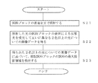
- FIG. 3 is a flowchart of the sample block surface determination method in the thin-section sample preparation method according to the first embodiment.
- a method for determining the surface area of the sample block in this thin-section sample preparation method will be described below with reference to FIG.
- (A) The reflected light of the irradiated light from the surface of the sample block 1 is received, and image data for two or more different colors is obtained (S01).
- (B) Based on the obtained image data for two or more colors of light, the portion of the sample 11 on the surface of the sample block 1 and the portion of the embedding agent 12 are identified (S02).
- S02 Based on the obtained image data for two or more colors of light, the portion of the sample 11 on the surface of the sample block 1 and the portion of the embedding agent 12 are identified (S02).
- (C) It is determined whether the area of the portion of the sample 11 on the surface of the obtained sample block 1 is sufficient for the preparation of the thin slice sample (S03).
- the portion of the sample 11 and the portion of the embedding agent 12 on the surface of the sample block 1 can be identified based on the obtained image data of light of two or more colors. .
- the sample 11 portion and the embedding agent 12 portion on the surface of the sample block 1 can be identified based on the color difference based on the image data for the light of two or more colors without depending only on the brightness data. Therefore, since it can be determined whether the portion of the sample 11 appears sufficiently on the surface of the sample block 1, it is possible to improve the accuracy of the surface determination of the sample block 1 in the preparation of the thin slice sample.
- FIG. 5 is a flowchart of the thin-section sample preparation method according to Embodiment 1 of the present invention. It is a flowchart of the production method of the slide glass 63 with the thin slice sample 32 concretely using FIG.
- the sample block 1 is conveyed from the position adjustment unit 50 to the surface determination unit 10 by the sample block conveyance unit 20 (S53).
- the surface determination unit 10 determines whether the area of the portion of the sample 11 on the surface of the sample block 1 is sufficient for the preparation of the thin-section sample as described above (S54). Note that the surface determination unit 10 may perform a step of detecting the area of the entire surface of the sample block 1 for the sample block 1 before rough cutting in the apparatus, as will be described in the second embodiment described later. . Further, a step of detecting the area of the maximum projection area of the sample in the sample block 1 may be performed. After performing a predetermined amount of rough cutting, the surface determination unit 10 determines whether or not the portion of the sample 11 on the surface of the sample block 1, that is, whether the exposed surface area of the surface after slicing is sufficient for thin slice sample preparation. Make a decision.
- the extension section 70 performs the first heating (for example, about 40 ° C. to 60 ° C. for several seconds to several tens of seconds) on the conveyed slide glass 63 with a thin section, and While extending the eyelids, the adhesive force of the thin slice sample 32 to the slide glass 63 is strengthened. Thereafter, the second heating (for example, about 40 ° C. for several hours) is further performed to completely evaporate the moisture and to fix the thin slice sample 32 to the slide glass 22 (S62). Thereby, the production of the slide glass 63 with the thin slice sample 32 is completed. Thereafter, the sample block 1 is transported by the sample block transport unit 20 in the same manner as described above, and the thin slice operation is automatically and continuously repeated any number of times, thereby preparing an arbitrary number of thin slice samples 32. it can.
- the first heating for example, about 40 ° C. to 60 ° C. for several seconds to several tens of seconds
- FIG. 6 is a schematic diagram illustrating the configuration of the sample block surface determination unit 10a in the thin-section sample preparation device according to the second embodiment.
- the sample block surface determination unit 10a has an incident light irradiation unit 3a and a diffused light irradiation unit as irradiation units as compared to the sample block surface determination unit in the thin-section sample preparation device according to the first embodiment. It is different in that it includes two irradiation parts different from 3b.
- the incident light irradiation unit 3a means a light source that irradiates the surface of the sample block with light from the regular reflection position with respect to the photographing unit 4.
- the diffused light irradiation unit 3b means a light source that irradiates light from a position that is not in a regular reflection position with respect to the imaging unit 4 on the surface of the sample block. Furthermore, by providing the diffused light irradiating unit 3b, by using the image data based on the diffused light, the maximum projection region (the portion surrounded by the dotted line in FIG. 7B) Smax of the biological sample 11 that is not exposed is used. It can be detected.
- the inspection range can be grasped even if the size of the sample block 1 changes.
- FIG. 7A is a cross-sectional view of the sample block 1 after rough cutting as viewed from the front direction
- FIG. 7B is a dotted line showing the maximum projection area of the sample 11 that is not exposed in the sample block 1 after rough cutting.
- FIG. 13 is a schematic diagram for explaining the principle of using diffused light to detect the maximum projection area of the sample 11 in the sample block 1 in the flowchart of FIG. 10 described later.
- the inventor receives the diffused light DI-2 reflected by the sample 11 that is not exposed to the surface with respect to the light that has entered the sample block 1 at the maximum. It has been found that the area Smax of the projection region can be detected.
- FIG. 8 is a flowchart of the sample block surface determination method in the thin-section sample preparation method according to the second embodiment.
- A The entire area of the surface of the sample block 1 in which the sample 11 is embedded with the embedding agent 12 is detected (S10).
- B The maximum projection area Smax of the sample 11 in the cross section parallel to the surface of the sample block 1 is detected (S20). Normally, the steps (a) and (b) up to here are performed before roughing in the present apparatus, and after this step (b), roughing is performed.
- C The part of the sample 11 and the part of the embedding agent 12 on the surface of the sample block 1 are identified (S30).
- D) It is determined whether the area of the portion of the sample 11 on the surface of the obtained sample block 1 is sufficient for the preparation of the thin-section sample (S40). The details of each step will be described below.
- FIG. 9 is a flowchart showing details of the step (S10) of detecting the entire area of the surface of the sample block of FIG. (A-1)
- the surface of the sample block is irradiated with light (S11).
- light is irradiated by the incident light irradiation unit 3a of FIG.
- the amount of light from the incident light irradiation unit 3a may be increased so that the amount of received light is larger than in the normal case.
- A-2 The regular reflection light of the irradiated light from the surface of the sample block 1 is received to obtain image data (S12).
- the amount of light from the incident light irradiation unit 3a may be increased in the previous step, the light reception gain may be set high, or the light reception time may be increased.
- the light may be received with a light reception amount that is twice or more the normal light reception amount.
- the amount of light received that is at least twice that of the normal amount of light received is one measure, and is the amount of light received that can illuminate the entire upper surface of the sample block 1 compared to the other part, particularly the sample stage 13. I just need it.
- the amount of received light is increased to the extent that the surface is bright as a whole regardless of the portion of the sample 11 and the portion of the embedding agent 12, that is, the whole becomes white.
- the amount of received light is saturated by the reflected light from the surface in the photographing unit 4.
- the entire area of the surface of the sample block is detected (S13). That is, the surface area of the upper surface of the sample block 1 can be obtained by subjecting the obtained image data to a light / dark binarization process. In this case, the portion of the sample 11 on the surface and the portion of the embedding agent 12 are not distinguished. Note that the entire area of the surface is the inspection range. Thereby, even if the size of the sample block 1 changes, the inspection range can be grasped.
- FIG. 10 is a flowchart showing details of the step (S20) of detecting the maximum projection area of the sample 11 in the cross section parallel to the surface of the sample block 1 of FIG. (B-1)
- the surface of the sample block is irradiated with light of two or more colors having different wavelengths (S21).
- light is irradiated by the diffused light irradiation unit 3b in FIG. (B-2)
- the diffused light from the surface of the sample block of the irradiated light is received to obtain image data for light of two or more colors (S22).
- the diffused lights DI-2 and DI-3 can be received also from the portion of the sample 11 that is not exposed on the surface of the sample block 1.
- the cross section C-1 of the portion of the sample 11 that is not exposed obtained by the diffused light DI-2 is different from the cross section C-2 of the portion of the sample 11 that is not exposed that is obtained by the diffused light DI-3.
- the maximum projection area Smax means an area obtained by projecting the maximum spread area of the sample on the surface, not a single cross section.
- the maximum projection area of the sample 11 of the sample block 1 is detected based on the obtained image data for light of two or more colors (S23). In this case, using the color difference between the embedding agent 12, for example, paraffin and the biological sample 11, not only the portion of the biological sample 11 appearing on the surface within the inspection range but also the unexposed biological sample 11.
- the detection method of the portion of the biological sample 11 based on the image data for the light of two or more colors may be combined with the determination of the portion of the biological sample 11 using the light / dark data based on the luminance information. That is, determination based only on luminance information for each color of RGB and determination using feature values of at least two colors from RGB may be combined with each other. Furthermore, the maximum projection area of the biological sample 11 that is not exposed can be detected by using image data based on diffused light.
- FIG. 11 is a flowchart showing details of the step (S30) of identifying the portion of the sample 11 and the portion of the embedding agent 12 on the surface of the sample block 1 of FIG. (C-1)
- the surface of the sample block 1 is irradiated with light of two or more colors having different wavelengths (S31).
- light is irradiated by the incident light irradiation unit 3a of FIG. (C-2)
- the regular reflection light of the irradiated light from the surface of the sample block 1 is received to obtain image data for light of two or more colors (S32).
- FIG. 12 is a step of determining whether or not the area of the portion of the sample 11 on the surface of the obtained sample block 1 of FIG. 8, that is, the exposed surface area of the surface after slicing is sufficient for the preparation of the thin slice sample (S40). It is a flowchart which shows the specific content of these. (D-1) The ratio S / Smax of the area S of the portion of the sample 11 on the surface of the sample block 1 to the area Smax of the maximum projection region of the sample 11 is calculated (S41).
- step S40 for determining whether or not the area of the portion of the sample 11 on the surface of the obtained sample block 1 is sufficient for producing the thin-section sample.
- the thin-section sample preparation apparatus and the thin-section sample preparation method according to the present invention do not depend only on the light / dark data obtained based on the luminance information of the image data, and the sample portion and the embedding agent on the surface of the sample block. Since it is possible to discriminate from the portion and determine whether the area of the portion of the sample is sufficient for the preparation of a thin slice sample, it is possible to prepare a thin slice sample for use in a physicochemical analysis or a microscopic observation of a biological sample. It is useful for a section sample preparation method and apparatus.
Landscapes
- Physics & Mathematics (AREA)
- Health & Medical Sciences (AREA)
- Life Sciences & Earth Sciences (AREA)
- Chemical & Material Sciences (AREA)
- Analytical Chemistry (AREA)
- Biochemistry (AREA)
- General Health & Medical Sciences (AREA)
- General Physics & Mathematics (AREA)
- Immunology (AREA)
- Pathology (AREA)
- Investigating Or Analysing Materials By Optical Means (AREA)
- Sampling And Sample Adjustment (AREA)
Abstract
La présente invention concerne un dispositif de préparation d'échantillons sur lame mince en coupant avec un cutter des films minces de la couche de surface d'un bloc échantillon comprenant un échantillon incorporé dans un milieu d'incorporation. Ce dispositif de préparation d'échantillons sur lame mince comprend un cutter destiné à couper des films minces de la surface du bloc échantillon, une unité de détermination de l'exposition de la surface destinée à déterminer si oui ou non la surface de la partie d'échantillon à la surface du bloc échantillon est suffisamment grande pour la préparation de l'échantillon sur lame mince, et une unité de transport du bloc échantillon destinée à transporter le bloc échantillon. L'unité de détermination de l'exposition de la surface comprend : une unité d'irradiation destinée à irradier avec de la lumière la surface du bloc échantillon comprenant l'échantillon incorporé dans le milieu d'incorporation ; une unité d'imagerie recevant la lumière irradiée par l'unité d'irradiation et réfléchie par la surface du bloc échantillon, et obtenant des données images de la lumière ayant deux couleurs ou plus différentes les unes des autres ; une unité de traitement des données images qui, en se basant sur les données images de la lumière ayant deux couleurs ou plus obtenues par l'unité d'imagerie, permet de différencier la partie échantillon de la surface du bloc échantillon et le milieu d'incorporation ; et une unité de contrôle permettant de contrôler l'unité d'imagerie, l'unité d'irradiation, et l'unité de traitement des données images et de déterminer si oui ou non la surface de la partie d'échantillon à la surface du bloc échantillon obtenue grâce à l'unité de traitement des données images est suffisamment grande pour la préparation de l'échantillon sur lame mince.
Applications Claiming Priority (2)
| Application Number | Priority Date | Filing Date | Title |
|---|---|---|---|
| JP2011-098482 | 2011-04-26 | ||
| JP2011098482A JP2012229993A (ja) | 2011-04-26 | 2011-04-26 | 薄切片試料作製装置及び薄切片試料作製方法 |
Publications (1)
| Publication Number | Publication Date |
|---|---|
| WO2012147730A1 true WO2012147730A1 (fr) | 2012-11-01 |
Family
ID=47072248
Family Applications (1)
| Application Number | Title | Priority Date | Filing Date |
|---|---|---|---|
| PCT/JP2012/060952 Ceased WO2012147730A1 (fr) | 2011-04-26 | 2012-04-24 | Dispositif de préparation d'échantillons sur lame mince |
Country Status (2)
| Country | Link |
|---|---|
| JP (1) | JP2012229993A (fr) |
| WO (1) | WO2012147730A1 (fr) |
Cited By (6)
| Publication number | Priority date | Publication date | Assignee | Title |
|---|---|---|---|---|
| WO2013118699A1 (fr) * | 2012-02-08 | 2013-08-15 | サクラファインテックジャパン株式会社 | Dispositif et procédé de préparation de tranche mince |
| WO2015002070A1 (fr) * | 2013-07-03 | 2015-01-08 | サクラファインテックジャパン株式会社 | Dispositif de fabrication de tranches minces et procédé de fabrication de tranches minces |
| WO2018090008A3 (fr) * | 2016-11-14 | 2018-06-14 | Sakura Finetek U.S.A., Inc. | Microtome |
| US11435268B2 (en) | 2020-02-22 | 2022-09-06 | Clarapath, Inc. | Facing and quality control in microtomy |
| US11959835B2 (en) | 2020-10-23 | 2024-04-16 | Clarapath, Inc. | Preliminary diagnoses of cut tissue sections |
| US12498298B2 (en) | 2021-12-20 | 2025-12-16 | Clarapath, Inc. | Automated tissue section system with cut quality prediction |
Families Citing this family (3)
| Publication number | Priority date | Publication date | Assignee | Title |
|---|---|---|---|---|
| JP2017009286A (ja) * | 2013-09-30 | 2017-01-12 | 倉敷紡績株式会社 | 薄切片試料作製装置および薄切片試料作製方法 |
| WO2015046518A1 (fr) * | 2013-09-30 | 2015-04-02 | 倉敷紡績株式会社 | Dispositif d'évaluation d'échantillons coupés en tranches, dispositif de préparation d'échantillons coupés en tranches comprenant ledit dispositif d'évaluation d'échantillons coupés en tranches et procédé d'évaluation d'échantillons coupés en tranches |
| ES3019361T3 (en) * | 2018-11-20 | 2025-05-20 | Leanap Inc | Sample imaging and imagery archiving for imagery comparison |
Citations (6)
| Publication number | Priority date | Publication date | Assignee | Title |
|---|---|---|---|---|
| JPH06258578A (ja) * | 1993-03-04 | 1994-09-16 | Kanagawa Kagaku Gijutsu Akad | 試料断面からの立体情報画像化装置及びその試料断面画像の観察方法 |
| JPH10123054A (ja) * | 1996-10-23 | 1998-05-15 | Kagaku Gijutsu Shinko Jigyodan | 試料観察方法及びその装置 |
| JP2004037459A (ja) * | 2002-06-28 | 2004-02-05 | Leica Mikrosysteme Gmbh | ミクロトーム、とりわけウルトラミクロトーム |
| JP2007212276A (ja) * | 2006-02-09 | 2007-08-23 | Seiko Instruments Inc | 薄切片作製装置及び薄切片の作製方法 |
| JP2008020293A (ja) * | 2006-07-12 | 2008-01-31 | Seiko Instruments Inc | 薄切片作製装置及び薄切片作製方法 |
| JP2010044069A (ja) * | 2008-08-08 | 2010-02-25 | Leica Biosystems Nussloch Gmbh | 画像認識システムを用いてサンプルの薄切片を作製する方法及び装置 |
-
2011
- 2011-04-26 JP JP2011098482A patent/JP2012229993A/ja active Pending
-
2012
- 2012-04-24 WO PCT/JP2012/060952 patent/WO2012147730A1/fr not_active Ceased
Patent Citations (6)
| Publication number | Priority date | Publication date | Assignee | Title |
|---|---|---|---|---|
| JPH06258578A (ja) * | 1993-03-04 | 1994-09-16 | Kanagawa Kagaku Gijutsu Akad | 試料断面からの立体情報画像化装置及びその試料断面画像の観察方法 |
| JPH10123054A (ja) * | 1996-10-23 | 1998-05-15 | Kagaku Gijutsu Shinko Jigyodan | 試料観察方法及びその装置 |
| JP2004037459A (ja) * | 2002-06-28 | 2004-02-05 | Leica Mikrosysteme Gmbh | ミクロトーム、とりわけウルトラミクロトーム |
| JP2007212276A (ja) * | 2006-02-09 | 2007-08-23 | Seiko Instruments Inc | 薄切片作製装置及び薄切片の作製方法 |
| JP2008020293A (ja) * | 2006-07-12 | 2008-01-31 | Seiko Instruments Inc | 薄切片作製装置及び薄切片作製方法 |
| JP2010044069A (ja) * | 2008-08-08 | 2010-02-25 | Leica Biosystems Nussloch Gmbh | 画像認識システムを用いてサンプルの薄切片を作製する方法及び装置 |
Cited By (23)
| Publication number | Priority date | Publication date | Assignee | Title |
|---|---|---|---|---|
| JP2013160719A (ja) * | 2012-02-08 | 2013-08-19 | Sakura Finetek Japan Co Ltd | 薄切片作製装置及び薄切片作製方法 |
| US9164014B2 (en) | 2012-02-08 | 2015-10-20 | Sakura Finetek Japan Co., Ltd. | Thin section fabrication apparatus and method of fabricating thin section |
| WO2013118699A1 (fr) * | 2012-02-08 | 2013-08-15 | サクラファインテックジャパン株式会社 | Dispositif et procédé de préparation de tranche mince |
| US10018535B2 (en) | 2013-07-03 | 2018-07-10 | Sakura Finetek Japan Co., Ltd | Thin-slice manufacturing device and thin-slice manufacturing method |
| WO2015002070A1 (fr) * | 2013-07-03 | 2015-01-08 | サクラファインテックジャパン株式会社 | Dispositif de fabrication de tranches minces et procédé de fabrication de tranches minces |
| AU2017357124B2 (en) * | 2016-11-14 | 2020-03-05 | Sakura Finetek U.S.A., Inc. | Microtome |
| US10012567B2 (en) | 2016-11-14 | 2018-07-03 | Sakura Finetek U.S.A., Inc. | Microtome chuck with light source |
| US10422724B2 (en) | 2016-11-14 | 2019-09-24 | Sakura Finetek U.S.A., Inc. | Microtome waste removal assembly |
| US10466143B2 (en) | 2016-11-14 | 2019-11-05 | Sakura Finetek U.S.A., Inc. | Microtome storage assembly |
| JP2019534461A (ja) * | 2016-11-14 | 2019-11-28 | サクラ ファインテック ユー.エス.エー., インコーポレイテッド | ミクロトーム |
| WO2018090008A3 (fr) * | 2016-11-14 | 2018-06-14 | Sakura Finetek U.S.A., Inc. | Microtome |
| US11112337B2 (en) | 2016-11-14 | 2021-09-07 | Sakura Finetek U.S.A., Inc. | Microtome with generator |
| JP7003128B2 (ja) | 2016-11-14 | 2022-01-20 | サクラ ファインテック ユー.エス.エー., インコーポレイテッド | ミクロトーム |
| US11467071B2 (en) | 2020-02-22 | 2022-10-11 | Clarapath, Inc. | Facing and quality control in microtomy |
| US11435268B2 (en) | 2020-02-22 | 2022-09-06 | Clarapath, Inc. | Facing and quality control in microtomy |
| US11609162B2 (en) | 2020-02-22 | 2023-03-21 | Clarapath, Inc. | Facing and quality control in microtomy |
| US11821826B2 (en) | 2020-02-22 | 2023-11-21 | Clarapath, Inc. | Facing and quality control in microtomy |
| US11898948B2 (en) | 2020-02-22 | 2024-02-13 | Clarapath, Inc. | Facing and quality control in microtomy |
| US12158404B2 (en) | 2020-02-22 | 2024-12-03 | Clarapath, Inc. | Facing and quality control in microtomy |
| US12405194B2 (en) | 2020-02-22 | 2025-09-02 | Clarapath, Inc. | Facing and quality control in microtomy |
| US11959835B2 (en) | 2020-10-23 | 2024-04-16 | Clarapath, Inc. | Preliminary diagnoses of cut tissue sections |
| US12292360B2 (en) | 2020-10-23 | 2025-05-06 | Clarapath, Inc. | Preliminary diagnoses of cut tissue sections |
| US12498298B2 (en) | 2021-12-20 | 2025-12-16 | Clarapath, Inc. | Automated tissue section system with cut quality prediction |
Also Published As
| Publication number | Publication date |
|---|---|
| JP2012229993A (ja) | 2012-11-22 |
Similar Documents
| Publication | Publication Date | Title |
|---|---|---|
| JP5766004B2 (ja) | 薄切片試料作製装置及び薄切片試料作製方法 | |
| WO2012147730A1 (fr) | Dispositif de préparation d'échantillons sur lame mince | |
| US11435268B2 (en) | Facing and quality control in microtomy | |
| CN102834712B (zh) | 带树脂覆膜的钢板的表面检查方法及其表面检查装置 | |
| JP5825278B2 (ja) | 欠陥検査装置および欠陥検査方法 | |
| WO2010024082A1 (fr) | Système d’inspection des défauts et procédé d’inspection des défauts | |
| CN110389021A (zh) | 透镜图像产生系统及屈光能力和厚度确定与缺陷检测方法 | |
| JP6483022B2 (ja) | 薄切片試料評価装置、該薄切片試料評価装置を含む薄切片試料作製装置、及び、薄切片試料評価方法 | |
| CN110402386A (zh) | 圆筒体表面检查装置及圆筒体表面检查方法 | |
| JP6782449B2 (ja) | 表面検査方法及びその装置 | |
| WO2020195137A1 (fr) | Dispositif et procédé d'inspection | |
| TW201727219A (zh) | 薄膜檢查裝置及薄膜檢查方法 | |
| KR20150138007A (ko) | 두께 판단 방법, 장치 및 시스템 | |
| JP2023142887A (ja) | 欠陥検査装置及び欠陥検査方法 | |
| JP2016125817A (ja) | 検査システム、検査方法 | |
| JP2020177032A (ja) | 検査装置及び検査方法 | |
| JP2014186030A (ja) | 欠点検査装置 | |
| JP2016148520A (ja) | キズ欠点検査装置およびキズ欠点検査方法 |
Legal Events
| Date | Code | Title | Description |
|---|---|---|---|
| 121 | Ep: the epo has been informed by wipo that ep was designated in this application |
Ref document number: 12777217 Country of ref document: EP Kind code of ref document: A1 |
|
| NENP | Non-entry into the national phase |
Ref country code: DE |
|
| 122 | Ep: pct application non-entry in european phase |
Ref document number: 12777217 Country of ref document: EP Kind code of ref document: A1 |