WO2012147738A1 - Appareil à embrayage centrifuge - Google Patents
Appareil à embrayage centrifuge Download PDFInfo
- Publication number
- WO2012147738A1 WO2012147738A1 PCT/JP2012/060965 JP2012060965W WO2012147738A1 WO 2012147738 A1 WO2012147738 A1 WO 2012147738A1 JP 2012060965 W JP2012060965 W JP 2012060965W WO 2012147738 A1 WO2012147738 A1 WO 2012147738A1
- Authority
- WO
- WIPO (PCT)
- Prior art keywords
- clutch
- clutch shoe
- centrifugal
- retaining
- swing shaft
- Prior art date
- Legal status (The legal status is an assumption and is not a legal conclusion. Google has not performed a legal analysis and makes no representation as to the accuracy of the status listed.)
- Ceased
Links
Images


Classifications
-
- F—MECHANICAL ENGINEERING; LIGHTING; HEATING; WEAPONS; BLASTING
- F16—ENGINEERING ELEMENTS AND UNITS; GENERAL MEASURES FOR PRODUCING AND MAINTAINING EFFECTIVE FUNCTIONING OF MACHINES OR INSTALLATIONS; THERMAL INSULATION IN GENERAL
- F16D—COUPLINGS FOR TRANSMITTING ROTATION; CLUTCHES; BRAKES
- F16D43/00—Automatic clutches
- F16D43/02—Automatic clutches actuated entirely mechanically
- F16D43/04—Automatic clutches actuated entirely mechanically controlled by angular speed
- F16D43/14—Automatic clutches actuated entirely mechanically controlled by angular speed with centrifugal masses actuating the clutching members directly in a direction which has at least a radial component; with centrifugal masses themselves being the clutching members
- F16D43/18—Automatic clutches actuated entirely mechanically controlled by angular speed with centrifugal masses actuating the clutching members directly in a direction which has at least a radial component; with centrifugal masses themselves being the clutching members with friction clutching members
-
- F—MECHANICAL ENGINEERING; LIGHTING; HEATING; WEAPONS; BLASTING
- F16—ENGINEERING ELEMENTS AND UNITS; GENERAL MEASURES FOR PRODUCING AND MAINTAINING EFFECTIVE FUNCTIONING OF MACHINES OR INSTALLATIONS; THERMAL INSULATION IN GENERAL
- F16D—COUPLINGS FOR TRANSMITTING ROTATION; CLUTCHES; BRAKES
- F16D43/00—Automatic clutches
- F16D43/02—Automatic clutches actuated entirely mechanically
- F16D43/04—Automatic clutches actuated entirely mechanically controlled by angular speed
- F16D43/14—Automatic clutches actuated entirely mechanically controlled by angular speed with centrifugal masses actuating the clutching members directly in a direction which has at least a radial component; with centrifugal masses themselves being the clutching members
- F16D2043/145—Automatic clutches actuated entirely mechanically controlled by angular speed with centrifugal masses actuating the clutching members directly in a direction which has at least a radial component; with centrifugal masses themselves being the clutching members the centrifugal masses being pivoting
Definitions
- the present invention relates to a centrifugal clutch device capable of transmitting or interrupting a driving force of a driving means by causing a clutch shoe to contact or separate from an inner peripheral wall surface of a driven side rotation member via a friction material by a centrifugal force. .
- a clutch device is usually disposed in a transmission path through which the driving force of the vehicle engine should be transmitted to the driving wheels, and the centrifugal force is used as a main clutch device to transmit or shut off the driving force.
- a clutch device may be mentioned.
- Such a centrifugal clutch device includes, as disclosed in, for example, Patent Document 1, a drive plate connected to an engine crankshaft, and a clutch shoe that is swingably disposed on a swing shaft of the drive plate. And a housing having an inner peripheral wall surface that can be contacted via a friction material (facing) when the clutch shoe is swung by centrifugal force.
- the friction material When the drive plate rotates as the engine is driven, a centrifugal force is applied to the clutch shoe and the shaft swings about the swing shaft. Therefore, when the rotational speed of the drive plate exceeds a certain value, the friction material The power is transmitted in contact with the inner peripheral wall surface.
- the surface facing the inner peripheral wall surface of the clutch shoe is formed in an arc shape following the inner peripheral wall surface of the housing, and a friction material is fixed to the arc-shaped surface.
- damper means for applying friction to the side surface of the clutch shoe.
- the damper means is composed of a metal plate, a disc spring, and the like, and is configured such that the metal plate can be brought into contact with the side surface of the clutch shoe by the biasing force of the disc spring while having elasticity. By applying friction, it has become possible to suppress the judder phenomenon and the like.
- the damper means composed of a metal plate and a disc spring for imparting friction to the side surface of the clutch shoe is disposed, the axial direction of the centrifugal clutch device is There was a problem that the size would increase. Further, in addition to the metal plate and the disc spring, a washer or the like for fixing the metal plate is required, so that the number of parts is increased and the manufacturing cost is deteriorated.
- the present invention has been made in view of such circumstances, and it is possible to suppress the judder phenomenon and the like by applying friction to the side surface of the clutch shoe, and to reduce the size in the axial direction of the device and reduce the size.
- An object of the present invention is to provide a centrifugal clutch device that can reduce the number of components.
- the invention according to claim 1 is attached to a driving side rotating member rotatable around an axis connected to the driving means, and a swing shaft formed on the driving side rotating member, and applied with a centrifugal force.
- a clutch shoe capable of swinging on the outer diameter side of the drive-side rotating member with the swing shaft as a center, and the drive-side rotating member are independently rotatably accommodated, and the inner periphery of the clutch shoe is swung in the swinging direction.
- a driven-side rotating member having a wall surface is fixed to a surface of the clutch shoe facing the inner peripheral wall surface, and contacts the inner peripheral wall surface when the clutch shoe is swung by centrifugal force.
- a centrifugal clutch device comprising: a friction material that transmits a driving force to a driven side rotating member to rotate; and a retaining means for preventing the clutch shoe from slipping from a swing shaft of the driving side rotating member. Missing Because means is characterized in that it consists of locking plate material for omission bent in the clutch shoe side had contact with the pressure contact portion while having elasticity on the side surface of the clutch shoe.
- the invention according to claim 2 is the centrifugal clutch device according to claim 1, wherein the retaining plate is fixed to the swing shaft.
- the retaining plate is assembled such that the press contact portion is in surface contact with the side surface of the clutch shoe.
- the retaining plate has a fixing portion in which an insertion hole through which the swing shaft can be inserted is formed.
- a retaining means is attached to the projecting end side of the fixed portion of the moving shaft so as to fix the retaining plate material to the swing shaft, and further to the outer diameter side of the retaining means of the fixing portion. Is characterized in that a bent portion formed by bending on the locking means side is formed.
- the retaining means comprises the retaining plate material that has a pressure contact portion that is bent toward the clutch shoe side and is elastically abutted against the side surface of the clutch shoe.
- the retaining plate is fixed to the swing shaft, the retaining of the clutch shoe can be ensured and the retaining plate can be securely fixed. Can be made.
- the press-contact portion is assembled with the press contact portion being in surface contact with the side surface of the clutch shoe, the friction is more stably and reliably applied to the side surface of the clutch shoe. be able to.
- the retaining plate has a fixing portion formed with an insertion hole through which the swing shaft can be inserted, and the locking means is provided on the protruding end side from the fixed portion of the swing shaft.
- the retaining plate is configured to be fixed to the rocking shaft, and a bent portion formed by bending to the locking means side is formed on the outer diameter side of the locking means in the fixing portion. Further, it is possible to prevent the locking means from coming off to the outer diameter side due to the centrifugal force when the driving side rotating member rotates.
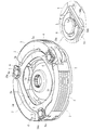
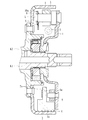
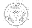
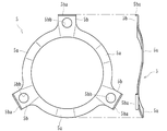
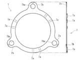
- the perspective view which shows the centrifugal clutch apparatus which concerns on 1st Embodiment of this invention Sectional drawing which shows the state which attached the centrifugal clutch apparatus to the vehicle Top view showing the centrifugal clutch device (with the retaining plate removed)
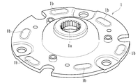
- the perspective view which shows the drive plate (drive side rotation member) in the centrifugal clutch apparatus The perspective view which shows the state which attached the rocking
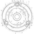
- FIG. 1 The perspective view which shows the centrifugal clutch apparatus which concerns on 2nd Embodiment of this invention.
- the centrifugal clutch device is disposed in a transmission path that should transmit the driving force of the engine of the vehicle to the driving wheels, and the clutch shoe abuts against the inner peripheral wall surface of the housing via the friction material by the centrifugal force.
- it is called a wet clutch device that can transmit or cut off the driving force of the engine by being separated from each other.
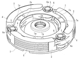
- a drive plate 1 as a driving side rotating member and a clutch shoe 2
- a housing 3 as a driven side rotating member and a retaining plate 5 as a retaining means.
- the drive plate 1 is made of a disk-like member that is rotatable around a clutch shaft L1 connected to the engine, and is rotatable by driving the engine.
- the drive plate 1 is disposed so that the peripheral edge thereof faces the inner peripheral wall surface 3a of the housing 3, and rotates with the housing 3 in a state where the friction material 4 is in contact with the inner peripheral wall surface 3a. 4 is rotatable independently of the housing 3 in a state of being separated from the inner peripheral wall surface 3a.
- the drive plate 1 has a contact projection 1b formed by coining or the like at the position where the clutch shoe 2 is disposed.
- the contact convex portion 1b is formed in an oval shape in a plan view while projecting to the front surface side (clutch shoe 2 side) of the figure, and the side surface of the clutch shoe 2 (retaining stopper) in a state where the clutch shoe 2 is assembled. It can come into contact with the side surface opposite to the surface with which the plate material 5 abuts. Thereby, the rocking
- a rocking shaft L is formed at a predetermined portion of the drive plate 1 (a portion corresponding to the position where the clutch shoe 2 is disposed), and the clutch shoe is formed on the rocking shaft L. 2 can be attached.
- a mounting hole 1a having a spline formed on the inner peripheral surface is formed at the center (rotation center) of the drive plate 1, and the clutch shaft L1 is inserted into the mounting hole 1a.
- the spline formed on the outer peripheral surface of the clutch shaft L1 is fitted into the spline of the mounting hole 1a.
- the three clutch shoes 2 are formed on the surface side of the drive plate 1 at substantially equal intervals in the circumferential direction.
- Each clutch shoe 2 is formed by laminating a plurality of iron plate materials and has a predetermined weight.
- the clutch shoe 2 is swingable about the swing axis L. When a centrifugal force is applied by rotation of the drive plate 1, the clutch shoe 2 swings toward the outer diameter side (outside) of the drive plate 1. It is possible to move.
- the clutch shoe 2 may be integrally formed of one material instead of a laminate of a plurality of plate-like members.
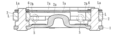
- the clutch shoe 2 has a pressure contact portion 2a that can come into contact with the retaining plate 5 on the side surface thereof as shown in FIGS.
- the pressure contact portion 2a is formed of a flat surface formed at a low position (a low position in the thickness direction of the clutch shoe 2 in FIG. 5) of the side surfaces of the clutch shoe 2, and the clutch shoe 2 and the retaining member are prevented from coming off the drive plate 1.
- the pressure contact portion 5a of the retaining plate material 5 can come into contact with the pressure contact portion 2a.
- the housing 3 is a container having a drive plate 1 that is independently rotatable and having an inner peripheral wall surface 3a in the swinging direction of the clutch shoe 2 as described above, and is provided with an output shaft L2 ( (See FIG. 2).
- the output shaft L2 is connected to drive wheels via a vehicle transmission or the like, and the drive plate 1 and the housing 3 rotate together with the friction material 4 in contact with the inner peripheral wall surface 3a.
- the driving force of the engine is configured to be transmitted to the driving wheels via the output shaft L2.
- the friction material 4 is fixed to a surface of the clutch shoe 2 facing the inner peripheral wall surface 3a.
- the friction material 4 comes into contact with the inner peripheral wall surface 3a to transmit the driving force of the engine to the housing 3. It is for transmitting to and rotating. That is, when the friction material 4 comes into contact with the inner peripheral wall surface 3a, the rotational force on the drive plate 1 side is transmitted to the housing 3 side by the friction force.
- coil springs S are connected between the adjacent clutch shoes 2, and when the rotation of the drive plate 1 is reduced and the centrifugal force is reduced, each clutch shoe 2 is in the initial state. Configured to return to position. However, as shown in FIG. 2, a damper T is formed at a predetermined position of the drive plate 1, and the clutch shoe 2 is made to interfere with the inner peripheral wall surface 3a by causing the clutch shoe 2 to interfere with the damper T. Oscillation of the process of contacting or separating is regulated.
- the retaining plate 5 as a retaining means is for retaining the clutch shoe 2 with respect to the swing shaft L of the drive plate 1.
- the retaining plate 5 is made of a metal plate having a substantially annular shape.
- the retaining plate 5 may be any material as long as it has flexibility and elasticity due to restoring force. However, when considering the strength, for example, a metal plate such as SUS is used. It is preferable to use it.
- the clutch shoe 2 is configured to be swingably held between the retaining plate 5 and the drive plate 1.
- the retaining plate 5 is bent toward the clutch shoe 2 and is pressed against the side surface of the clutch shoe 2 while having elasticity.
- it has a fixing portion 5b in which an insertion hole 5bb into which the swing shaft L can be inserted is formed. That is, in a state where the clutch shoe 2 is assembled to the swing shaft L of the drive plate 1, the retaining plate 5 is fixed by inserting the insertion hole 5bb of the fixing portion 5b into the protruding end side of the swing shaft L. Due to the elasticity of the retaining plate 5 itself, the pressure contact portion 5a can come into contact with the side surface (pressure contact portion 2a) of the clutch shoe 2 while having elasticity.
- the pressure contact portion 5a abuts the side surface (pressure contact portion 2a) of the clutch shoe 2 with elasticity and presses the clutch shoe 2 toward the drive plate 1 (contact convex portion 1b). Friction can be applied to the side surface of the shoe 2, and judder phenomenon and the like can be suppressed.
- the press contact portion 5a is configured by a surface formed over a predetermined range, the press contact portion 5a is in surface contact with the side surface (the press contact portion 2a) of the clutch shoe 2. It can be pressed with elasticity. Therefore, according to the present embodiment, the retaining plate 5 is assembled with the press contact portion 5a in surface contact with the side surface of the clutch shoe 2 (the press contact portion 2a). Thus, the friction can be applied more stably and reliably.
- a groove La (see FIG. 5) is formed in the circumferential direction on the protruding end side from the portion through which the fixing portion 5b is inserted in the swing shaft L, and an E-shape as a locking means is formed in the groove La.
- a ring 6 (E-shaped circlip) is attached to fix the retaining plate 5. That is, the retaining plate 5 is fixed to the swing shaft L by attaching the E-shaped ring 6 as a locking means to the protruding end side of the fixed portion 5b of the swing shaft L.
- a bent portion formed by bending the outer side (outside) of the E-shaped ring 6 (locking means) in the fixed portion 5b toward the E-shaped ring 6 (locking means). 5ba is formed.
- E-shaped ring 6 (locking means) remove
- the E-shaped ring 6 is attached to the groove La of the rocking shaft L so that the notch 6a is positioned on the outer diameter side (outer side), and due to the centrifugal force applied when the drive plate 1 rotates. It is more reliably prevented from coming off the swinging shaft L.
- the retaining means is composed of the retaining plate 5 having the pressure contact portion 5a that is bent toward the clutch shoe 2 side and is in contact with the side surface of the clutch shoe 2 while having elasticity.
- the retaining plate 5 can have both a retaining function of the clutch shoe 2 with respect to the swing shaft L and a function of imparting friction to the side surface of the clutch shoe 2 and is imparted by the retaining plate 5. Friction can be easily set with a dimension to be bent toward the clutch shoe 2 side. Furthermore, since the E-shaped ring 6 as a locking means is attached to the groove La of the swing shaft L and the retaining plate 5 is fixed, the retaining plate 5 can be positioned more easily and reliably. The desired friction can be imparted to the side surface of the clutch shoe 2.
- the clutch shoe 2 can be reliably prevented from being detached, and the retaining plate 5 can be secured. Fixing can be performed reliably.
- the fixing of the retaining plate 5 to the rocking shaft L is not limited to that by the E-shaped ring 6 (locking means) as described above, but by other general-purpose locking means or a locking method (caulking or the like). It may be a thing.
- the centrifugal clutch device according to the second embodiment is disposed in a transmission path through which the driving force of the engine of the vehicle is to be transmitted to the drive wheels, and the clutch shoe is housed via the friction material by the centrifugal force.
- This is called a dry clutch device that can transmit or cut off the driving force of the engine by contacting or separating from the inner peripheral wall surface of the motor, and as shown in FIGS. It is mainly composed of a plate 1, a clutch shoe 2, a housing 3 as a driven side rotating member, and a retaining plate 7 as a retaining means.
- symbol is attached
- the retaining plate 7 as a retaining means is intended to prevent the clutch shoe 2 from slipping off the rocking shaft L of the drive plate 1, and in this embodiment, as shown in FIG. It is made of a metal plate having a substantially annular shape.
- the retaining plate 7 may be any material as long as it has flexibility and elasticity due to restoring force. However, when considering the strength, for example, a metal plate such as SUS material is used. It is preferable to use it.
- the clutch shoe 2 is configured to be swingably held between the retaining plate 7 and the drive plate 1.
- the retaining plate 7 is bent toward the clutch shoe 2 and is in contact with the side surface of the clutch shoe 2 while having elasticity.
- a fixing portion 7b formed with an insertion hole 7ba through which the swing shaft L can be inserted. That is, in a state where the clutch shoe 2 is assembled to the swing shaft L of the drive plate 1, the retaining plate 7 is fixed by inserting the insertion hole 7ba of the fixing portion 7b into the protruding end side of the swing shaft L. Due to the elasticity of the retaining plate 7 itself, the pressure contact portion 7a can come into contact with the side surface (pressure contact portion 2a) of the clutch shoe 2 while having elasticity.
- the pressure contact portion 7a abuts the side surface (pressure contact portion 2a) of the clutch shoe 2 with elasticity, and presses the clutch shoe 2 toward the drive plate 1 (contact convex portion 1b). Friction can be applied to the side surface of the shoe 2, and judder phenomenon and the like can be suppressed.
- the pressure contact portion 7a is formed in a wave shape (protrusion) bent toward the clutch shoe 2, the number of wave shapes to be formed (2 in this embodiment) is arbitrarily set. By setting, the friction applied to the side surface (the pressed contact portion 2a) of the clutch shoe 2 can be adjusted as desired.
- the retaining means includes the pressure contact portion 7a that is bent toward the clutch shoe 2 and is in contact with the side surface of the clutch shoe 2 while having elasticity, as in the first embodiment. Since the plate material 7 is used, the judder phenomenon and the like can be suppressed by applying friction to the side surface of the clutch shoe 2, and the axial dimension of the centrifugal clutch device can be reduced and the size can be reduced. Since the friction can be applied only by the stopping plate material 7, the number of parts can be reduced.
- the retaining plate member 7 can have both the retaining function of the clutch shoe 2 with respect to the swing shaft L and the function of imparting friction to the side surface of the clutch shoe 2, and the friction imparted by the retaining plate member 7. Can be easily set by a dimension to be bent toward the clutch shoe 2 side. Further, as in the first embodiment, since the E-shaped ring 6 as the locking means is attached to the groove La of the swing shaft L and the retaining plate 7 is fixed, the retaining plate 7 is positioned. Thus, desired friction can be applied to the side surface of the clutch shoe 2.
- the clutch shoe 2 can be reliably prevented from being detached, and the retaining plate 7 can be secured. Fixing can be performed reliably.
- the fixing of the retaining plate 7 to the swing axis L is not limited to the one using the E-shaped ring 6 (locking means) as described above, as in the first embodiment. It is good also by the stop method (caulking etc.).
- this invention is not limited to these, For example, suppose that the board
- the retaining means is a centrifugal clutch device made of a retaining plate having a pressure contact portion that is bent toward the clutch shoe side and has elasticity on the side surface of the clutch shoe, the outer shape may be different. It can also be applied to those to which the above function is added.
Landscapes
- Engineering & Computer Science (AREA)
- General Engineering & Computer Science (AREA)
- Mechanical Engineering (AREA)
- One-Way And Automatic Clutches, And Combinations Of Different Clutches (AREA)
Abstract
L'objet de la présente invention est de fournir un appareil à embrayage centrifuge permettant de supprimer tout phénomène de vibrations et similaire en communiquant un frottement à une surface latérale d'une masselotte d'embrayage, de réduire les dimensions axiales de l'appareil en vue de produire un appareil plus compact et de réduire le nombre de composants. La présente invention a trait à un appareil à embrayage centrifuge qui est équipé : d'un plateau d'entraînement (1) ; de masselottes d'embrayage (2) ; d'un logement (3) qui est doté d'une surface de paroi périphérique intérieure (3a) ; d'éléments de frottement (4) permettant de transmettre au logement (3) la force d'entraînement d'un moyen d'entraînement et de faire en sorte que le logement tourne, les éléments de frottement étant fixés à une surface opposée à la surface de paroi périphérique intérieure (3a) dans les masselottes d'embrayage (2) et venant en butée contre la surface de paroi périphérique intérieure (3a) lorsque les masselottes d'embrayage (2) sont balancées par la force centrifuge ; et d'un moyen d'arrêt permettant d'arrêter les masselottes d'embrayage (2) par rapport aux arbres à balancement (L) du plateau d'entraînement (1) ; lequel moyen d'arrêt comprend une plaque d'arrêt (5) qui est dotée de parties de contact par pression (5a) incurvées vers les masselottes d'embrayage (2) et poussées à venir buter avec une force élastique contre une surface latérale des masselottes d'embrayage (2).
Priority Applications (1)
| Application Number | Priority Date | Filing Date | Title |
|---|---|---|---|
| CN201280019865.1A CN103502674B (zh) | 2011-04-26 | 2012-04-24 | 离心式离合器装置 |
Applications Claiming Priority (2)
| Application Number | Priority Date | Filing Date | Title |
|---|---|---|---|
| JP2011097848A JP5758687B2 (ja) | 2011-04-26 | 2011-04-26 | 遠心クラッチ装置 |
| JP2011-097848 | 2011-04-26 |
Publications (1)
| Publication Number | Publication Date |
|---|---|
| WO2012147738A1 true WO2012147738A1 (fr) | 2012-11-01 |
Family
ID=47072256
Family Applications (1)
| Application Number | Title | Priority Date | Filing Date |
|---|---|---|---|
| PCT/JP2012/060965 Ceased WO2012147738A1 (fr) | 2011-04-26 | 2012-04-24 | Appareil à embrayage centrifuge |
Country Status (3)
| Country | Link |
|---|---|
| JP (1) | JP5758687B2 (fr) |
| CN (1) | CN103502674B (fr) |
| WO (1) | WO2012147738A1 (fr) |
Families Citing this family (7)
| Publication number | Priority date | Publication date | Assignee | Title |
|---|---|---|---|---|
| JP2016041944A (ja) | 2014-08-14 | 2016-03-31 | 株式会社マキタ | 遠心クラッチ装置 |
| JP5913497B2 (ja) * | 2014-09-17 | 2016-04-27 | 株式会社エクセディ | 遠心式クラッチ装置 |
| JP5925266B2 (ja) * | 2014-09-17 | 2016-05-25 | 株式会社エクセディ | 遠心式クラッチ装置 |
| JP6200474B2 (ja) * | 2015-10-08 | 2017-09-20 | 株式会社エフ・シー・シー | 遠心クラッチ |
| CN114251382B (zh) * | 2021-12-28 | 2024-07-09 | 中铁十一局集团有限公司 | 双向超越离合器 |
| JP7191268B1 (ja) | 2022-09-01 | 2022-12-16 | 株式会社エフ・シー・シー | 遠心クラッチ組付け装置 |
| KR102620031B1 (ko) * | 2023-10-19 | 2024-01-02 | 이영석 | 원심클러치를 이용한 전동식 이동대차 |
Citations (2)
| Publication number | Priority date | Publication date | Assignee | Title |
|---|---|---|---|---|
| JPS62104033U (fr) * | 1985-12-23 | 1987-07-02 | ||
| JPH0418725U (fr) * | 1990-06-08 | 1992-02-17 |
Family Cites Families (5)
| Publication number | Priority date | Publication date | Assignee | Title |
|---|---|---|---|---|
| DE19721747B4 (de) * | 1997-05-24 | 2014-06-05 | Andreas Stihl Ag & Co. | Fliehkörperkupplung |
| JP4588195B2 (ja) * | 2000-11-06 | 2010-11-24 | 本田技研工業株式会社 | 小型車両の動力伝達装置 |
| JP4229274B2 (ja) * | 2003-08-26 | 2009-02-25 | 本田技研工業株式会社 | 内燃機関の遠心式クラッチにおける給油装置 |
| JP4364668B2 (ja) * | 2004-02-17 | 2009-11-18 | 本田技研工業株式会社 | 遠心クラッチ |
| JP4054818B2 (ja) * | 2005-07-20 | 2008-03-05 | 株式会社エクセディ | 遠心式クラッチ装置 |
-
2011
- 2011-04-26 JP JP2011097848A patent/JP5758687B2/ja not_active Expired - Fee Related
-
2012
- 2012-04-24 WO PCT/JP2012/060965 patent/WO2012147738A1/fr not_active Ceased
- 2012-04-24 CN CN201280019865.1A patent/CN103502674B/zh not_active Expired - Fee Related
Patent Citations (2)
| Publication number | Priority date | Publication date | Assignee | Title |
|---|---|---|---|---|
| JPS62104033U (fr) * | 1985-12-23 | 1987-07-02 | ||
| JPH0418725U (fr) * | 1990-06-08 | 1992-02-17 |
Also Published As
| Publication number | Publication date |
|---|---|
| JP2012229730A (ja) | 2012-11-22 |
| JP5758687B2 (ja) | 2015-08-05 |
| CN103502674B (zh) | 2016-04-13 |
| CN103502674A (zh) | 2014-01-08 |
Similar Documents
| Publication | Publication Date | Title |
|---|---|---|
| JP5758687B2 (ja) | 遠心クラッチ装置 | |
| JP5502507B2 (ja) | 動力伝達装置 | |
| JP5747259B2 (ja) | ドライダブルクラッチ | |
| JP6617051B2 (ja) | クラッチ装置 | |
| WO2016024557A1 (fr) | Dispositif de transmission de puissance | |
| JP6961427B2 (ja) | 動力伝達装置 | |
| US11460077B2 (en) | Power transmission device | |
| JP2018504567A (ja) | デカップラ | |
| CN102725555B (zh) | 离心式离合器设备 | |
| WO2017154554A1 (fr) | Appareil amortisseur | |
| JP7522546B2 (ja) | クラッチ装置 | |
| JP2000213598A (ja) | トルク伝達装置 | |
| JPH1182630A (ja) | トルク伝達装置 | |
| CN111108304B (zh) | 扭矩传递装置、扭转阻尼器及相关组件 | |
| JP2005282651A (ja) | 捩り振動低減装置 | |
| JPH0725478Y2 (ja) | トルク変動吸収装置 | |
| KR101963027B1 (ko) | 자동차 클러치디스크의 프릭션부싱 | |
| JP4194103B2 (ja) | 多重摩擦部材を有するクラッチダンパディスクアセンブリ | |
| WO2016042941A1 (fr) | Dispositif d'embrayage de type centrifuge | |
| JP2023084447A (ja) | ダンパー装置 | |
| JP2000346168A (ja) | トルク伝達装置 | |
| JP2010084933A (ja) | 捩り振動低減装置 | |
| JP2008038992A (ja) | スプリングクラッチ | |
| JPH11280843A (ja) | 捩じりダンパ | |
| JP2012225480A (ja) | トーショナルダンパ |
Legal Events
| Date | Code | Title | Description |
|---|---|---|---|
| 121 | Ep: the epo has been informed by wipo that ep was designated in this application |
Ref document number: 12776685 Country of ref document: EP Kind code of ref document: A1 |
|
| NENP | Non-entry into the national phase |
Ref country code: DE |
|
| 122 | Ep: pct application non-entry in european phase |
Ref document number: 12776685 Country of ref document: EP Kind code of ref document: A1 |