WO2012147789A1 - Dispositif pour fabriquer un échantillon à section mince - Google Patents
Dispositif pour fabriquer un échantillon à section mince Download PDFInfo
- Publication number
- WO2012147789A1 WO2012147789A1 PCT/JP2012/061082 JP2012061082W WO2012147789A1 WO 2012147789 A1 WO2012147789 A1 WO 2012147789A1 JP 2012061082 W JP2012061082 W JP 2012061082W WO 2012147789 A1 WO2012147789 A1 WO 2012147789A1
- Authority
- WO
- WIPO (PCT)
- Prior art keywords
- sample block
- sample
- height
- thin
- height position
- Prior art date
- Legal status (The legal status is an assumption and is not a legal conclusion. Google has not performed a legal analysis and makes no representation as to the accuracy of the status listed.)
- Ceased
Links
- 0 CCCC(C1CCC1)C(C1)C(C(CCNC)*2CCC2)C1(C(C*C*C)C(**C)N1CC1)C(CN)C1CCC1 Chemical compound CCCC(C1CCC1)C(C1)C(C(CCNC)*2CCC2)C1(C(C*C*C)C(**C)N1CC1)C(CN)C1CCC1 0.000 description 3
Images



Classifications
-
- G—PHYSICS
- G01—MEASURING; TESTING
- G01N—INVESTIGATING OR ANALYSING MATERIALS BY DETERMINING THEIR CHEMICAL OR PHYSICAL PROPERTIES
- G01N1/00—Sampling; Preparing specimens for investigation
- G01N1/02—Devices for withdrawing samples
- G01N1/04—Devices for withdrawing samples in the solid state, e.g. by cutting
- G01N1/06—Devices for withdrawing samples in the solid state, e.g. by cutting providing a thin slice, e.g. microtome
-
- G—PHYSICS
- G01—MEASURING; TESTING
- G01B—MEASURING LENGTH, THICKNESS OR SIMILAR LINEAR DIMENSIONS; MEASURING ANGLES; MEASURING AREAS; MEASURING IRREGULARITIES OF SURFACES OR CONTOURS
- G01B5/00—Measuring arrangements characterised by the use of mechanical techniques
- G01B5/02—Measuring arrangements characterised by the use of mechanical techniques for measuring length, width or thickness
- G01B5/06—Measuring arrangements characterised by the use of mechanical techniques for measuring length, width or thickness for measuring thickness
- G01B5/061—Measuring arrangements characterised by the use of mechanical techniques for measuring length, width or thickness for measuring thickness height gauges
Definitions
- the present invention relates to a thin-section sample preparation apparatus for preparing a thin-section sample used for physicochemical sample analysis or microscopic observation of biological samples.
- a microtome is known as this type of device.
- a microtome is an apparatus for producing a thin slice sample by slicing a specimen embedded with paraffin or the like with a cutter.
- a thin slice sample prepared by a microtome is attached to a slide glass and used as a thin slice sample for tissue observation.
- the preparation work of a thin section sample using a microtome has been conventionally performed manually by an operator, and requires a lot of labor and labor. Further, the thickness required for the thin slice sample is very thin (for example, 3 ⁇ m to 10 ⁇ m, although it varies depending on the sample), and high uniformity is also required. For this reason, even an operator skilled in the use of a microtome usually takes several days to process dozens of sample blocks. Further, since the same work is repeated, an excessive burden is imposed on the worker physically and mentally.
- This type of device adjusts the height position of the cutter and the sample block so that the cutter can slice the surface layer portion of the sample block, and then transports the sample block toward the cutter to produce a thin slice sample.
- This type of device is configured as follows.
- a predetermined amount of rough cutting is performed to perform surface matching, and then the main cutting is performed when the exposed area of the sample block becomes appropriate.
- the surface layer portion of the sample block is inclined with respect to the extending direction of the cutting edge of the cutter or the conveying direction of the sample block, rough cutting takes too much time. For this reason, it is important to adjust the position of the sample block so that the surface layer portion of the sample block is parallel to the extending direction of the cutting edge of the cutter and the conveying direction of the sample block.
- Patent Document 1 Japanese Patent Application Laid-Open No. 2008-76251 discloses a method in which a line sensor is provided and a sample block is surfaced (surface matching) based on a change in the amount of light received by the line sensor. Note that adjusting the position of the sample block so that it is parallel is sometimes referred to as “face-up”, but in the field of thin-section sample preparation equipment, the term “face-up” refers to “the subject on the surface of the sample block. May be effectively exposed ". For this reason, in order to avoid misunderstanding, here, adjusting the position of the sample block so that the surface layer portion of the sample block is parallel to the extending direction of the cutting edge of the cutter and the conveying direction of the sample block is referred to as “surface matching. "
- an object of the present invention is to provide a thin-section sample preparation device that can solve the above-described problems and can perform the surface alignment of the sample blocks more accurately.
- a thin-section sample preparation device for preparing a thin-section sample by slicing a surface layer portion of a sample block with a cutter,
- a sample block cutting section comprising the cutter;
- a sample block transport unit configured to adjust an inclination angle of the sample block with respect to an XY orthogonal two-axis direction and a height position in the Z-axis direction, and transports the sample block in the X-axis direction;
- a height detector for detecting a height position of the sample block;
- a control unit for adjusting the tilt angle and the height position of the sample block based on detection information of the height detection unit;
- the height detection unit is configured to contact at least three measurement points that are not collinear with the surface layer portion of the sample block, and detect at least three contact points to detect the height positions of the at least three measurement points.
- the thin-section sample preparation device according to the first aspect, wherein the three measurement points are located inside the outer edge of the sample block.
- the height detection unit can detect the height position of the fourth measurement point by contacting the fourth measurement point located approximately at the center of the sample block.
- the thin-section sample preparation apparatus according to the first or second aspect, further comprising a fourth contact sensor.
- the control unit adjusts the tilt angle of the sample block, and then causes the height detection unit to detect the height position of the sample block again, and the height detection unit. Based on the detected information, the sample block transport unit is controlled to readjust the inclination angle of the sample block, and the height detecting unit detects the height position of the sample block, and the height of the sample block is determined.
- the thin-section sample preparation device according to any one of the first to third aspects, in which the position is adjusted, is provided.
- the height detection unit since the height detection unit includes the three contact sensors, three measurement points that are not collinear with the surface layer portion of the sample block are provided.
- the height position of the three measurement points can be detected by contact.
- the tilt angle and height position of the sample block can be detected.
- it since it is a contact-type sensor, even if a foreign material has adhered to the surface of the sample block, the possibility that the height position of the sample block is erroneously detected by the foreign material can be suppressed. Therefore, the surface alignment of the sample block can be performed more accurately.
- FIG. 1 is a block diagram showing a schematic configuration of a thin-section sample preparation device according to an embodiment of the present invention.
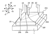
- FIG. 2 is a perspective view showing a schematic configuration of the height detection unit
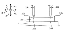
- FIG. 3 is a side view schematically showing a state in which the contact sensor is brought into contact with the surface layer portion of the sample block.
- FIG. 4 is a side view schematically showing a state in which the contact sensor is brought into contact with the surface layer portion of the sample block adjusted to be parallel to the XY plane.
- FIG. 1 is a block diagram showing a schematic configuration of a thin-section sample preparation device according to an embodiment of the present invention.
- FIG. 2 is a perspective view showing a schematic configuration of the height detection unit
- FIG. 3 is a side view schematically showing a state in which the contact sensor is brought into contact with the surface layer portion of the sample block.
- FIG. 4 is a side view schematically showing a state in which the contact sensor is brought into contact with the surface layer portion of the sample block adjusted
- FIG. 5 is a side view schematically showing a state in which the surface layer portion of the sample block finely adjusted to be parallel to the XY plane from the state shown in FIG. 4 is brought into contact with the contact sensor.
- FIG. 6 is a side view schematically showing a state in which a contact sensor provided in the height detection unit shown in FIG. 2 is brought into contact with a sample block whose surface is warped inward.
- FIG. 7 is a perspective view showing a schematic configuration of a modified example of the height detection unit
- FIG. 8 is a side view schematically showing a state in which the contact sensor provided in the height detection unit shown in FIG. 7 is brought into contact with the sample block whose surface is warped inward.
- FIG. 1 is a block diagram showing a schematic configuration of a thin-section sample preparation apparatus according to an embodiment of the present invention.
- a thin-section sample preparation apparatus 100 is an apparatus that forms a plurality of thin-section samples 24 by automatically and continuously slicing the surface layer portion of the sample block 20 with a cutter 41.
- the sample block 20 is obtained by embedding the subject 20a in an embedding material such as paraffin.
- Examples of the subject 20a include biological samples such as human and animal tissues.
- the thin-section sample preparation apparatus 100 includes a sample block storage unit 30 that stores a plurality of sample blocks 20.
- One sample block 20 selected from the plurality of sample blocks 20 stored in the sample block storage unit 30 is transported by the sample block transport unit 1 to the sample block cutting unit 4 including the cutter 41.
- the sample block transport unit 1 is configured such that after the sample block 20 to be sliced next is taken out from the sample block storage unit 30 and transported onto the position A, the sample block 20 can be transported back and forth between the positions A to C. Has been.
- the positions A to C are linearly aligned in the ⁇ X axis direction. That is, the sample block transport unit 1 is configured to be able to transport the sample block 20 in the X-axis direction.
- the sample block transport unit 1 is configured to be able to adjust the tilt angle of the sample block 20 with respect to the XY orthogonal biaxial direction (also referred to as the XY plane) and the height position in the Z axis direction.
- a height detection unit 2 for detecting the height position of the sample block 20 is arranged.
- the configuration of the height detection unit 2 will be described in detail later.
- the image pickup unit 3 that picks up an image of the cut surface of the sample block 20 sliced and exposed by the cutter 41 is disposed.
- the imaging unit 3 is configured to have a portion that irradiates the surface of the sample block, such as a white light source or a monochromatic LED light source, and a photographing portion for obtaining image data such as a CCD camera.
- the sample block cutting section 4 is disposed that can hold the cutter 41 and slice the surface layer portion of the sample block 20. The cutter 41 is held such that the cutting edge extends in the ⁇ Y axis direction.
- a carrier tape 21 that holds a thin slice sample 24 obtained by slicing the surface layer portion of the sample block 20 with a cutter 41 is supplied.
- the carrier tape 21 is fed out from the supply reel 5, guided by the guide rollers 81 and 82, and supplied above the position C.
- the carrier tape 21 holding the sliced piece sample 24 above the position C is guided by the guide rollers 83 and 84 and taken up on the take-up reel 6.
- a feeding motor 51 is provided on the supply reel 5. By driving the feeding motor 51, the carrier tape 21 is fed from the supply reel 5.
- the take-up reel 6 is provided with a take-up motor 61.
- a constant torque is always applied to the take-up reel 6 by always driving the take-up motor 61.
- the carrier tape 21 fed out from the supply reel 5 by the driving of the feeding motor 51 is taken up on the take-up reel 6 simultaneously with the feeding out.
- the thin slice sample 24 held on the carrier tape 21 is stuck to the slide glass 22 by the thin slice sticking portion 7 disposed between the guide rollers 83 and 84.
- the thin-section pasting portion 7 is a pair of guide rollers 71 disposed on the upstream side ( ⁇ X axis direction side) of the traveling path of the carrier tape 21 and the downstream side (+ X axis direction side) of the traveling path of the carrier tape 21. And a pair of guide rollers 72 arranged.
- the thin slice pasting portion 7 is bent downward with the carrier tape 21 sandwiched between the pair of guide rollers 71 and 71 and the pair of guide rollers 72 and 72, and the thin slice sample 24 held on the carrier tape 21. Is brought into contact with the slide glass 22 supplied with an adhesive liquid 23 such as water. As a result, the thin slice sample 24 is attached to the slide glass 22.
- the slide glass to which the thin section sample 24 is attached is referred to as a slide glass with a thin section.
- the slide glass 22 with a thin section is transported to the extension unit 9 by the slide glass transport unit 8.
- the slide glass transport unit 8 transports the slide glass 22 with a thin section to the extension unit 9, and takes out the slide glass 22 to which the thin section sample 24 has not been pasted from the slide glass storage unit (not shown), and a thin section pasting unit. 7 is conveyed below.
- the extension unit 9 includes a heating plate (not shown), extends the folds of the thin slice sample 24, and completely evaporates the moisture on the slide glass 22, thereby closely attaching the thin slice sample 24 to the slide glass 22. Fix it.
- each component such as the sample block transport unit 1 is controlled by the control unit 10.
- the control unit 10 controls the operation of each component based on information input to an input unit (not shown).
- the input unit is configured to be able to input, for example, the number of manufactured slide glasses with thin sections, the number of thin section samples attached per slide glass, and the like.
- the manufacturing operation of the thin slice sample 24 will be described.
- the production operation of the thin slice sample 24 is performed under the control of the control unit 10.
- the subject 20a is embedded in the embedding material so as not to be exposed to the outside (or slightly exposed).
- the surface layer portion of the sample block 20 is roughened until the exposed area of the subject 20a is equal to or larger than a preset area, and then a thin slice sample 24 of about 3 to 10 ⁇ m is produced. I try to sharpen.
- the roughing operation will be described.
- the sample block transport unit 1 takes out the sample block 20 to be sliced next from the sample block storage unit 30 and transports it to the position A.
- the height detector 2 detects the height position of the sample block 20.
- the sample block transport unit 1 adjusts the inclination angle of the sample block 20 with respect to the XY plane and the height position in the Z-axis direction based on the detection information of the height detection unit 2.
- the sample block transport unit 1 transports the sample block 20 to the position B.
- the imaging unit 3 images the sample block 20.
- the maximum projection area (maximum projection area) of the subject 20a in the sample block 20 is recognized.
- the sample block transport unit 1 transports the sample block 20 to the position C. Thereby, the surface layer portion of the sample block 20 is roughly cut by the cutter 41.
- the sample block transport unit 1 transports the sample block 20 to the position B.
- the imaging unit 3 captures an image of the cut surface of the sample block 20 that is exposed by being sliced by the cutter 41.
- the sample block transport unit 1 uses the cutter 41 as the surface layer portion.
- the height position of the sample block 20 is adjusted so that it is roughly cut.
- the sample block transport unit 1 transports the sample block 20 to the position C.
- the surface layer portion of the sample block 20 is roughed again by the cutter 41.
- the sample block transport unit 1 transports the sample block 20 to the position B, and the imaging unit 3 captures the cutting surface of the sample block 20 again.
- the rough cutting of the sample block 20 and the imaging operation of the cutting surface are repeated until the exposed area of the subject 20a on the cutting surface of the sample block 20 is equal to or larger than a preset area.
- the rough cutting operation is terminated and the main cutting operation is started.
- the position of the cutting edge 41a of different cutter 41 or different cutter 41 for rough cutting and main cutting or when the thickness of rough cutting differs from the thickness of main cutting, the thickness accuracy of the section to be manufactured is improved. Therefore, at the position of the cutter 41 used for the main cutting or the cutting edge 41a of the cutter 41, a so-called discarding operation is performed in which the thin cutting sample 24 is thinly cut several times with the main cutting thickness before the thin section sample 24 is manufactured (before the main cutting). Is preferably performed.
- the sample block transport unit 1 adjusts the height position of the sample block 20 so that the surface layer portion of the sample block 20 is sliced by the cutter 41 (about 3 ⁇ m to 10 ⁇ m). Thereafter, the sample block transport unit 1 transports the sample block 20 to the position C. Thereby, the surface layer part of the sample block 20 is sliced by the cutter 41, and the thin slice sample 24 is produced. Thereafter, the sample block transport unit 1 retracts the sample block 20 from the position C to the position B or the like, and adjusts the height position of the sample block 20 so that the surface layer portion of the sample block 20 is sliced by the cutter 41.
- the operations of adjusting the height position of the sample block 20, slicing, and retracting are automatically and continuously repeated an arbitrary number of times based on information input to the input unit (not shown), and an arbitrary number of sheets A thin slice sample 24 is prepared.
- the thin slice sample 24 produced by the main cutting operation is affixed to the carrier tape 21.
- the surface of the carrier tape 21 is subjected to treatments such as humidification, cooling, and charging so that the thin slice sample 24 is securely attached to the carrier tape 21.
- the thin slice sample 24 affixed to the carrier tape 21 is conveyed to the thin slice affixing unit 7 by driving of the feeding motor 51 and the take-up motor 61 and affixed to the slide glass 22 by the thin segment affixing unit 7. Thereafter, the slide glass 22 with a thin section is conveyed to the extension unit 9 by the slide glass conveyance unit 8. Thereafter, the extension section 9 extends the folds of the thin slice sample 24 and closely fixes the thin slice sample 24 to the slide glass 22.
- FIG. 2 is a perspective view illustrating a schematic configuration of the height detection unit 2.
- the height detector 2 includes three contact sensors 2A, 2B, and 2C.
- Each of the contact sensors 2A, 2B, and 2C can detect the height position of the three measurement points by contacting the three measurement points 20b to 20d that are not on the same straight line with respect to the surface layer portion of the sample block 20.
- Each contact type sensor 2A, 2B, 2C is configured to detect, for example, the contact pressure with the surface layer portion of the sample block 20, and when the contact pressure of each sensor is the same, the inclination angle of the sample block 20 with respect to the XY plane is It is provided to be 0 degrees (that is, parallel to the extending direction of the cutting edge of the cutter 41 and the conveying direction of the sample block 20).
- the height detection operation of the sample block 20 by the height detection unit 2 is performed under the control of the control unit 10.
- the sample block transport unit 1 transports the sample block 20 to be sliced next from the sample block storage unit 30 to the position A.
- the sample block transport unit 1 moves the sample block 20 in the + Z-axis direction, and brings the surface layer portion of the sample block 20 into contact with the three contact sensors 2A, 2B, and 2C of the height detection unit 2.
- the contact sensors 2A, 2B, 2C detect the height position of the sample block 20.
- the inclination angle of the sample block 20 with respect to the XY plane is adjusted.
- the sample block transport unit 1 causes the sample block 20 so that the surface layer portion of the sample block 20 is parallel to the XY plane. Adjust the tilt angle.
- the rough cutting time of the thin slice sample 24 can be shortened and the rough cutting amount can be reduced by bringing the surface layer portion of the sample block 20 closer to the XY plane.
- it is preferable to make the surface layer portion of the sample block 20 completely parallel to the XY plane by this adjustment since the adjustment requires an accuracy of several ⁇ m level, it is practically difficult. For this reason, it is preferable to perform the following operation.
- the sample block transport unit 1 moves the sample block 20 in the + Z-axis direction, and re-contacts the surface layer portion of the sample block 20 with the three contact sensors 2A, 2B, 2C as shown in FIG. As a result, the contact sensors 2A, 2B, 2C redetect the height position of the sample block 20.
- the sample block transport unit 1 retracts the sample block 20 from the three contact sensors 2A, 2B, and 2C in the ⁇ Z axis direction
- the sample block 20 is finely adjusted with respect to the XY plane.
- the accuracy of making the surface layer portion of the sample block 20 parallel to the XY plane is improved. Note that the redetection and fine adjustment operations of the height position of the sample block 20 may be repeated until a desired accuracy is obtained.
- the sample block transport unit 1 moves the sample block 20 in the + Z-axis direction, and again brings the surface layer portion of the sample block 20 into contact with the three contact sensors 2A, 2B, and 2C as shown in FIG. Thereby, the contact-type sensors 2A, 2B, and 2C detect the height position of the sample block 20 again.
- the sample block transport unit 1 retracts the sample block 20 from the three contact sensors 2A, 2B, 2C in the ⁇ Z-axis direction.
- the sample is adjusted so that the height position of the measurement point located at the highest position among the three measurement points detected by the three contact sensors 2A, 2B, and 2C and the cutting edge of the cutter 41 coincide with each other.
- the block transport unit 1 adjusts the height position of the sample block 20.
- the sample block transport unit 1 transports the sample block 20 to the position C. Thereby, the surface layer portion of the sample block 20 is sliced by the cutter 41, and rough cutting can be performed in a shorter time, and the thin slice sample 24 is produced.
- the height detection unit 2 since the height detection unit 2 includes the three contact sensors 2A, 2B, and 2C, the three measurement points 20b that are not collinear with the surface layer portion of the sample block 20 are provided. , 20c and 20d, the height positions of the three measurement points can be detected. In particular, by detecting the height positions of the three measurement points 20b, 20c, and 20d twice, the fineness of the inclination angle of the sample block 20 with respect to the XY plane can improve the accuracy of the surface matching. .
- the contact type sensors 2A, 2B, and 2C are in contact with the surface layer portion of the sample block 20, even if foreign matter adheres to the surface of the sample block 20, the sample is caused by the foreign matter.
- the possibility of erroneous detection of the height position of the block 20 can be suppressed.
- paraffin waste as an embedding material adheres to the surface of the sample block 20 as a foreign substance.
- a fiber material such as a non-woven fabric may be used, but the fiber waste may adhere to the surface of the sample block 20.
- the thickness including the foreign matter will be detected.
- a contact-type sensor it is possible to exclude the thickness due to the foreign matter because the foreign matter can be pushed into the sample block 20 to some extent at the time of contact with paraffin waste. Therefore, the surface alignment of the sample block 20 using paraffin as the embedding material can be performed more accurately.
- the three measurement points 20b, 20c, and 20d at which the contact sensors 2A, 2B, and 2C detect the height position are located inside the outer edge portion 20e of the sample block 20.
- the sample block 20 is produced, for example, by placing a subject 20a in a plastic mold and then pouring paraffin into it. In this case, when removing the mold from the manufactured sample block 20, the surface of the sample block 20 may be warped (recessed) inward as shown in FIG. In this case, even if only the outer edge portion 20e of the sample block 20 is sliced, it cannot be used as the thin-section sample 24. Therefore, the time taken to slice the outer edge portion 20e is wasted.
- the sample block 20 generally has a surface size of 24 mm ⁇ 24 mm, 24 mm ⁇ 30 mm, 24 mm ⁇ 37 mm. For this reason, it is preferable that the space
- the sample block 20 has a surface size of 15 mm ⁇ 15 mm.
- the interval between the measurement points 20b, 20c, and 20d is preferably less than 15 mm. it is conceivable that.
- the distance between the measurement points 20b, 20c, and 20d becomes narrower, it becomes more difficult to detect the inclination angle of the surface layer portion of the sample block 20 with respect to the XY plane.
- the bottom of the concave portion on the surface of the sample block 20 is shown to be flat, but the bottom may be arcuate.
- the height detection unit 2 is in contact with the fourth measurement point 20f located approximately at the center of the sample block and can detect the height position of the measurement point 20f.
- a contact sensor 2D may be provided. This makes it possible to detect the height position in the vicinity of the lowest point of the concave portion on the surface of the sample block 20, thereby further shortening the production time of the thin slice sample 24.
- the fourth measurement point 20f is preferably located at the center of the sample block 20. As a result, the height position near the lowest point of the concave portion on the surface of the sample block 20 can be detected, and the production time of the thin-section sample 24 can be further shortened.
- the fourth measurement point 20f at approximately the center of the sample block 20
- the three contact sensors 2A, 2B, 2C cannot contact the sample block 20, and the apparatus may enter an error state and stop.
- at least the contact sensor 2D comes into contact with the sample block 20 by providing the fourth contact sensor 2D that can come into contact with the fourth measurement point 20f located approximately at the center of the sample block 20. Can do.
- the height position of the sample block 20 can be adjusted.
- the continuous operation state can be maintained without entering an error state.
- the thin-section sample preparation device can perform the surface alignment of the sample block more accurately, the thin-section sample preparation device is useful as a thin-section sample preparation device used for physicochemical sample analysis or microscopic observation of biological samples. is there.
Landscapes
- Physics & Mathematics (AREA)
- General Physics & Mathematics (AREA)
- Health & Medical Sciences (AREA)
- Life Sciences & Earth Sciences (AREA)
- Chemical & Material Sciences (AREA)
- Analytical Chemistry (AREA)
- Biochemistry (AREA)
- General Health & Medical Sciences (AREA)
- Immunology (AREA)
- Pathology (AREA)
- Sampling And Sample Adjustment (AREA)
Abstract
La présente invention concerne un dispositif servant à fabriquer un échantillon à section mince, le dispositif comprenant une unité de découpe de bloc à échantillon doté d'un dispositif de découpe pour entrer en contact avec plus de précision avec les surfaces des blocs à échantillon ; un dispositif de transport de bloc à échantillon servant à transporter le bloc à échantillon dans le sens de l'axe des X, le dispositif de transport de bloc à échantillon étant conçu pour permettre l'ajustement de la hauteur dans le sens de l'axe des Z et l'angle d'inclinaison par rapport au sens biaxial orthogonal XY du bloc à échantillon ; un détecteur de hauteur servant à détecter la hauteur du bloc à échantillon ; et un dispositif de commande servant à ajuster l'angle d'inclinaison et la hauteur du bloc à échantillon sur la base de la détection de la hauteur. Le détecteur de hauteur est doté de trois capteurs de contact pouvant entrer en contact avec trois points de mesure mutuellement différents sur la partie couche superficielle du bloc à échantillon afin de détecter la hauteur des trois points de mesure.
Applications Claiming Priority (2)
| Application Number | Priority Date | Filing Date | Title |
|---|---|---|---|
| JP2011098491A JP2012229996A (ja) | 2011-04-26 | 2011-04-26 | 薄切片試料作製装置 |
| JP2011-098491 | 2011-04-26 |
Publications (1)
| Publication Number | Publication Date |
|---|---|
| WO2012147789A1 true WO2012147789A1 (fr) | 2012-11-01 |
Family
ID=47072307
Family Applications (1)
| Application Number | Title | Priority Date | Filing Date |
|---|---|---|---|
| PCT/JP2012/061082 Ceased WO2012147789A1 (fr) | 2011-04-26 | 2012-04-25 | Dispositif pour fabriquer un échantillon à section mince |
Country Status (2)
| Country | Link |
|---|---|
| JP (1) | JP2012229996A (fr) |
| WO (1) | WO2012147789A1 (fr) |
Citations (6)
| Publication number | Priority date | Publication date | Assignee | Title |
|---|---|---|---|---|
| JPS59155511U (ja) * | 1983-04-05 | 1984-10-18 | 株式会社三幸製作所 | 工作物の研削面面振れ検査装置 |
| JP2002039741A (ja) * | 2000-07-19 | 2002-02-06 | Komai Tekko Inc | 物体表面の凹凸測定方法および装置 |
| JP2008020293A (ja) * | 2006-07-12 | 2008-01-31 | Seiko Instruments Inc | 薄切片作製装置及び薄切片作製方法 |
| JP2008076250A (ja) * | 2006-09-21 | 2008-04-03 | Kurabo Ind Ltd | 薄切片試料作製方法及び装置 |
| JP2008076251A (ja) * | 2006-09-21 | 2008-04-03 | Kurabo Ind Ltd | 試料ブロックの面出し方法 |
| JP2008134127A (ja) * | 2006-11-28 | 2008-06-12 | Seiko Instruments Inc | 自動薄切装置及び自動薄切方法 |
-
2011
- 2011-04-26 JP JP2011098491A patent/JP2012229996A/ja active Pending
-
2012
- 2012-04-25 WO PCT/JP2012/061082 patent/WO2012147789A1/fr not_active Ceased
Patent Citations (6)
| Publication number | Priority date | Publication date | Assignee | Title |
|---|---|---|---|---|
| JPS59155511U (ja) * | 1983-04-05 | 1984-10-18 | 株式会社三幸製作所 | 工作物の研削面面振れ検査装置 |
| JP2002039741A (ja) * | 2000-07-19 | 2002-02-06 | Komai Tekko Inc | 物体表面の凹凸測定方法および装置 |
| JP2008020293A (ja) * | 2006-07-12 | 2008-01-31 | Seiko Instruments Inc | 薄切片作製装置及び薄切片作製方法 |
| JP2008076250A (ja) * | 2006-09-21 | 2008-04-03 | Kurabo Ind Ltd | 薄切片試料作製方法及び装置 |
| JP2008076251A (ja) * | 2006-09-21 | 2008-04-03 | Kurabo Ind Ltd | 試料ブロックの面出し方法 |
| JP2008134127A (ja) * | 2006-11-28 | 2008-06-12 | Seiko Instruments Inc | 自動薄切装置及び自動薄切方法 |
Also Published As
| Publication number | Publication date |
|---|---|
| JP2012229996A (ja) | 2012-11-22 |
Similar Documents
| Publication | Publication Date | Title |
|---|---|---|
| JP5827490B2 (ja) | 薄切片試料作製装置 | |
| JP4503692B1 (ja) | 液晶表示素子を連続製造する装置において用いられる情報格納読出演算システム及び情報格納読出演算システムの製造方法 | |
| KR20140066551A (ko) | 릴-투-릴 검사장치 및 릴-투-릴 검사방법 | |
| TW201232689A (en) | Measurement means and method for measuring layer thicknesses and voids of a wafer stack | |
| JP6483022B2 (ja) | 薄切片試料評価装置、該薄切片試料評価装置を含む薄切片試料作製装置、及び、薄切片試料評価方法 | |
| WO2012147787A1 (fr) | Dispositif de préparation d'échantillon à section mince | |
| US8540543B2 (en) | Method for continuously manufacturing liquid crystal display panel and inspection method | |
| KR102671826B1 (ko) | 검사 장치, 판상물 제조장치, 검사 방법, 판상물 제조방법 | |
| JP4795181B2 (ja) | 試料ブロックの面出し方法 | |
| JP5022507B1 (ja) | 製品パネルの連続製造方法、検出システム及び検出方法 | |
| WO2015029998A1 (fr) | Dispositif de pelliculage, système et procédé de production de dispositif d'affichage optique | |
| JP4854442B2 (ja) | 薄切片試料作製方法及び装置 | |
| WO2012147789A1 (fr) | Dispositif pour fabriquer un échantillon à section mince | |
| WO2015046202A1 (fr) | Dispositif et procédé de production d'échantillons en tranches | |
| JP4769178B2 (ja) | 検査装置及びシート貼付装置 | |
| JP6476123B2 (ja) | 薄切片試料作製装置及び薄切片試料作製方法 | |
| TW201135212A (en) | Inspection method and device for cracks on rectangular sheet-like object | |
| JP2007218616A (ja) | 自動薄切装置、自動薄切片標本作製装置及び自動薄切方法 | |
| CN105283751A (zh) | 薄切片制作装置以及薄切片制作方法 | |
| JP4683425B2 (ja) | 自動薄切片作製装置及び自動薄切片標本作製装置並びに自動薄切片作製方法 | |
| KR102723091B1 (ko) | 복수의 분석 테스트 스트립을 제조하는 방법 및 시스템 | |
| JP4817320B2 (ja) | 薄切片標本作製装置及び薄切片標本作製方法 | |
| JP2010185818A (ja) | 薄切片作製システム | |
| JP5261534B2 (ja) | 検査装置 | |
| JP4148273B2 (ja) | 結晶方位測定方法及び結晶方位測定装置 |
Legal Events
| Date | Code | Title | Description |
|---|---|---|---|
| 121 | Ep: the epo has been informed by wipo that ep was designated in this application |
Ref document number: 12777439 Country of ref document: EP Kind code of ref document: A1 |
|
| NENP | Non-entry into the national phase |
Ref country code: DE |
|
| 122 | Ep: pct application non-entry in european phase |
Ref document number: 12777439 Country of ref document: EP Kind code of ref document: A1 |