WO2012147889A1 - 光通信装置及び光経路切替装置及びネットワーク - Google Patents
光通信装置及び光経路切替装置及びネットワーク Download PDFInfo
- Publication number
- WO2012147889A1 WO2012147889A1 PCT/JP2012/061285 JP2012061285W WO2012147889A1 WO 2012147889 A1 WO2012147889 A1 WO 2012147889A1 JP 2012061285 W JP2012061285 W JP 2012061285W WO 2012147889 A1 WO2012147889 A1 WO 2012147889A1
- Authority
- WO
- WIPO (PCT)
- Prior art keywords
- optical
- signal
- client
- communication device
- wavelength
- Prior art date
- Legal status (The legal status is an assumption and is not a legal conclusion. Google has not performed a legal analysis and makes no representation as to the accuracy of the status listed.)
- Ceased
Links
Images






Classifications
-
- H—ELECTRICITY
- H04—ELECTRIC COMMUNICATION TECHNIQUE
- H04J—MULTIPLEX COMMUNICATION
- H04J14/00—Optical multiplex systems
- H04J14/02—Wavelength-division multiplex systems
- H04J14/0227—Operation, administration, maintenance or provisioning [OAMP] of WDM networks, e.g. media access, routing or wavelength allocation
- H04J14/0238—Wavelength allocation for communications one-to-many, e.g. multicasting wavelengths
-
- H—ELECTRICITY
- H04—ELECTRIC COMMUNICATION TECHNIQUE
- H04J—MULTIPLEX COMMUNICATION
- H04J14/00—Optical multiplex systems
- H04J14/02—Wavelength-division multiplex systems
- H04J14/0201—Add-and-drop multiplexing
- H04J14/0202—Arrangements therefor
- H04J14/0204—Broadcast and select arrangements, e.g. with an optical splitter at the input before adding or dropping
-
- H—ELECTRICITY
- H04—ELECTRIC COMMUNICATION TECHNIQUE
- H04J—MULTIPLEX COMMUNICATION
- H04J14/00—Optical multiplex systems
- H04J14/02—Wavelength-division multiplex systems
- H04J14/0201—Add-and-drop multiplexing
- H04J14/0202—Arrangements therefor
- H04J14/0209—Multi-stage arrangements, e.g. by cascading multiplexers or demultiplexers
-
- H—ELECTRICITY
- H04—ELECTRIC COMMUNICATION TECHNIQUE
- H04J—MULTIPLEX COMMUNICATION
- H04J14/00—Optical multiplex systems
- H04J14/02—Wavelength-division multiplex systems
- H04J14/0201—Add-and-drop multiplexing
- H04J14/0202—Arrangements therefor
- H04J14/021—Reconfigurable arrangements, e.g. reconfigurable optical add/drop multiplexers [ROADM] or tunable optical add/drop multiplexers [TOADM]
- H04J14/0212—Reconfigurable arrangements, e.g. reconfigurable optical add/drop multiplexers [ROADM] or tunable optical add/drop multiplexers [TOADM] using optical switches or wavelength selective switches [WSS]
-
- H—ELECTRICITY
- H04—ELECTRIC COMMUNICATION TECHNIQUE
- H04J—MULTIPLEX COMMUNICATION
- H04J14/00—Optical multiplex systems
- H04J14/02—Wavelength-division multiplex systems
- H04J14/0201—Add-and-drop multiplexing
- H04J14/0202—Arrangements therefor
- H04J14/0213—Groups of channels or wave bands arrangements
-
- H—ELECTRICITY
- H04—ELECTRIC COMMUNICATION TECHNIQUE
- H04J—MULTIPLEX COMMUNICATION
- H04J14/00—Optical multiplex systems
- H04J14/02—Wavelength-division multiplex systems
- H04J14/0201—Add-and-drop multiplexing
- H04J14/0215—Architecture aspects
- H04J14/0217—Multi-degree architectures, e.g. having a connection degree greater than two
-
- H—ELECTRICITY
- H04—ELECTRIC COMMUNICATION TECHNIQUE
- H04Q—SELECTING
- H04Q11/00—Selecting arrangements for multiplex systems
- H04Q11/0001—Selecting arrangements for multiplex systems using optical switching
- H04Q11/0062—Network aspects
- H04Q11/0067—Provisions for optical access or distribution networks, e.g. Gigabit Ethernet Passive Optical Network (GE-PON), ATM-based Passive Optical Network (A-PON), PON-Ring
-
- H—ELECTRICITY
- H04—ELECTRIC COMMUNICATION TECHNIQUE
- H04L—TRANSMISSION OF DIGITAL INFORMATION, e.g. TELEGRAPHIC COMMUNICATION
- H04L27/00—Modulated-carrier systems
- H04L27/26—Systems using multi-frequency codes
- H04L27/2601—Multicarrier modulation systems
- H04L27/2697—Multicarrier modulation systems in combination with other modulation techniques
-
- H—ELECTRICITY
- H04—ELECTRIC COMMUNICATION TECHNIQUE
- H04Q—SELECTING
- H04Q11/00—Selecting arrangements for multiplex systems
- H04Q11/0001—Selecting arrangements for multiplex systems using optical switching
- H04Q11/0062—Network aspects
- H04Q2011/0086—Network resource allocation, dimensioning or optimisation
Definitions
- the present invention relates to an optical communication device having a function of converting a client signal of a client communication device such as a router into an optical signal suitable for transmission over an optical network, and converting a received optical signal into a client signal, and And a network composed of these devices and client communication devices, in particular, distributes client signals according to destinations and communication capacities for each destination, and divides them into a plurality of different central optical frequencies.
- the present invention relates to an optical communication device including means for converting to an optical signal and outputting, and an optical path switching device and a network including the optical communication device.
- wavelength division multiplexing networks which utilizes wavelength division multiplexing transmission technology in optical fiber transmission technology to associate optical signal wavelengths with transmission and reception grounds and realize multipoint-to-multipoint optical communications.
- Such optical wavelength division multiplexing networks connect optical path switching devices called ROADM (Reconfigurable Optical Add Drop Dropplexer) and WXC (Wavelength Cross Connection) with optical fiber.
- ROADM Reconfigurable Optical Add Drop Dropplexer
- WXC Widelength Cross Connection
- a ring-shaped or mesh-shaped optical wavelength division multiplexing network is constructed.
- a client signal of a client communication device such as a router is converted into an optical signal suitable for transmission on an optical network, and also has a function of converting a received optical signal into a client signal, via an optical communication device called an optical transponder. Connected to the optical path switching device.
- optical communication is performed between any client communication devices connected to the optical wavelength multiplexing network through a series of processing such as wavelength separation of wavelength-multiplexed optical signals, editing for each destination, and wavelength multiplexing.
- processing such as wavelength separation of wavelength-multiplexed optical signals, editing for each destination, and wavelength multiplexing.
- Optical signals in optical wavelength division multiplexing networks that are currently commercially introduced are placed on a frequency grid specified by ITU-T, and the interval between the center frequencies of adjacent optical signals is constant, for example, 100 GHz. is there.
- the center frequency interval between adjacent optical signals is set according to the requirements of individual optical signals.
- patent documents 1 and 2 and non-patent documents 1 and 2 have been proposed.
- WO2010 / 032844 “Variable Bandwidth Communication Device and Bandwidth Variable Communication Method”
- WO2011 / 030897 Bandwidth variable communication method, band variable communication device, transmission band determination device, transmission band determination method, node device, communication path setting system, and communication path setting method”
- the network side interface of the optical communication apparatus is as shown in the basic block example of the conventional optical communication apparatus in FIG.
- the transmission processing unit includes a client reception interface, an optical layer management information processing unit, and an electro-optical conversion unit
- the reception processing unit includes an opto-electric conversion unit, an optical layer management information processing unit, and a client transmission interface. Only a single optical signal is input / output.
- FIG. 2 shows an example of a conventional router network.
- the optical wavelength division multiplexing network which is the router network shown in FIG. 2, assigns one optical frequency (wavelength) between two communication points, and transfers an optical signal along a predesigned path using this optical frequency as a label.
- the client communication device connected to the optical network accepts the client signal and the network side interface of the optical communication device that is the starting point of the optical communication transmits and receives only a single optical signal. , Meaning point-to-point point-to-point connection.
- Non-Patent Document 1 an optical communication device capable of adaptively increasing an optical transmission capacity in response to an increase in communication demand of a client communication device has been researched and developed.
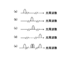
- FIG. 3 such an optical communication apparatus is a system in which the occupied optical spectrum width increases (increases the bit rate of one wavelength or increases the number of subcarriers) as the transmission capacity increases.
- the adjacent optical spectrum is occupied, the optical frequency needs to be changed, and the service is interrupted.
- client communication devices such as routers are arranged at a plurality of sites and are responsible for communication between these sites.
- client communication devices such as routers are arranged at a plurality of sites and are responsible for communication between these sites.
- the required number of client communication device ports and optical transponders increase with the square of the number of client communication devices, resulting in capital investment costs and maintenance. Increase costs. Therefore, in the conventional router network shown in FIG. 2, the client communication device port and the optical transponder are shared by a plurality of connections between the client communication devices, and the connection between the plurality of client communication devices is routed in the relay client communication device. This problem is avoided by sorting.
- the route distribution processing of relay client communication devices also increases, and there is concern that future data communication demands cannot be accommodated with realistic device size, power consumption, and device cost. Is spreading.
- the present invention has been made in view of the above points, and realizes a smooth change in the transmission capacity of an optical communication device, and does not increase the load on the relay client communication device via one port of the client communication device.
- An object of the present invention is to provide an optical communication device, an optical path switching device, and a network that realize communication with a plurality of client communication devices.
- An optical communication apparatus converts a client signal input from a client communication apparatus into an optical signal suitable for transmission over an optical network, and converts the received optical signal into a client signal.
- a communication device A distribution unit that distributes the input client signal into a plurality according to a destination and a communication capacity for each destination;
- Electro-optical conversion means for converting the distributed client signal into a plurality of optical signals having different central optical frequencies; Wavelength multiplexing means for wavelength-multiplexing and outputting the plurality of optical signals; Means for separating a plurality of wavelength multiplexed optical signals for each wavelength; Photoelectric conversion means for converting the separated optical signal into an electrical signal; Multiple output means for multiplexing a plurality of electrical signals converted by the photoelectric conversion means and outputting the multiplexed electrical signals as electrical signals or converted into optical signals as client signals. It is configured as a characteristic optical communication device.
- An optical path switching apparatus is an optical path switching apparatus having a function of multiplexing, demultiplexing, inserting, branching, and distributing a wavelength multiplexed signal, and an inserting / branching port includes the optical communication
- An optical input / output port to the apparatus is provided, and an optical frequency bandwidth for multiplexing, demultiplexing, inserting, branching, and route allocation is configured to be variable according to the optical spectrum width of the optical signal.
- a network includes an optical wavelength division multiplexing network in which a plurality of the optical path switching devices are connected by a plurality of optical fibers, and a plurality of client communication devices, and the client communication devices are the optical communication devices. It is a network that is connected via an optical communication device provided in an insertion / branching port of a route switching device, and that communicates between arbitrary client communication devices via a wavelength path, The input / output port of the client communication device has means for giving information identifying the destination to the client signal, One input / output port of an arbitrary client communication device is configured to be connected to the input / output ports of an arbitrary plurality of client communication devices via the optical communication device.
- the client signal is converted into a plurality of optical signals having different central optical frequencies according to the communication capacity of each destination and the destination, which could not be realized by the prior art, and wavelength multiplexing is performed.
- the arrangement of the center optical frequency of the optical signal carrying the increased traffic can be freely set. It becomes possible to reduce blocking due to spectrum collision with other optical signals.
- optical communication device for example, even when there is no free optical spectrum on the same route, the optical signal carrying the increased traffic is distributed to another route with free spectrum. This effect can be further enhanced.
- the client communication device side can be connected to an optical wavelength division multiplexing network using only one input / output port and connected to a plurality of other client communication devices.
- Multipoint connection can be realized.
- the number of connection destinations and the transmission capacity between them can be adjusted as needed on the client communication device side.
- a client communication device such as a router is connected to the optical wavelength division multiplexing network via the minimum number of ports and the optical communication device, and the necessary client communication via the minimum necessary number of relay client communication devices.
- 1 is a basic functional block diagram of an optical communication device in a first embodiment of the present invention. It is a figure which shows the example of optical frequency arrangement
- FIG. 4 is a diagram illustrating basic functional blocks of the optical communication apparatus according to the first embodiment of the present invention
- FIG. 5 illustrates an example of optical signal frequency arrangement.
- FIG. 4 includes a transmission processing unit 100 and a reception processing unit 200.
- the transmission processing unit 100 includes a client reception interface 110 that receives a client signal, a client signal distribution unit 120 that distributes the client signal into a plurality, an optical layer management information processing unit 130 that adds management information to the client signal, and transfers the communication amount It comprises an electro-optical conversion unit 140 that converts an optical signal having a central optical frequency assigned in association with a band and a path sufficient for the purpose, and an optical wavelength multiplexing output unit 150 that wavelength-multiplexes and outputs the converted optical signal.
- the client reception interface 110 receives a client signal from the client communication device, arranges the format of the received client signal, and outputs the client signal to the client signal distribution unit 120.
- the client signal received from the client communication device may be an electrical signal or an optical signal.
- the client signal may be a wavelength multiplexed optical signal obtained by multiplexing a plurality of wavelengths. If the client signal to be received is an optical signal, the client reception interface 110 converts the optical signal into an electrical signal and outputs the electrical signal to the client signal distribution unit 120.
- FIG. 4 illustrates, as an example, how the client signal input from the client reception interface 110 is distributed into four in the client signal distribution unit 120.
- the number to be distributed may be set freely, and each communication amount does not need to be the same.
- the client signal distribution unit 120 distributes an input client signal into a plurality according to a destination and a communication capacity for each destination.
- Each client signal distributed by the client signal distribution unit 120 is managed by the optical layer management information processing unit 130, for example, as management information (such as OTN (Optical Transport Network) defined by ITU-T® G.709). (Including error correction information).
- OTN Optical Transport Network
- ITU-T® G.709 Optical Transport Network
- the electro-optical conversion unit 140 converts the optical signal into a light signal having a center optical frequency designated by a network accommodation design device (not shown).
- the amount of traffic and the transfer distance for each distributed client signal are different. Therefore, when converting to an optical signal, the minimum necessary occupation is required according to the communication capacity and transfer distance required to transfer each client signal.
- the optical layer management information processing unit 130 and the electro-optical conversion unit 140 do not have to be a single device as shown in FIG. 4, and may be a plurality of devices for each distribution unit (in the case of FIG. 4). 4). It should be noted that the use of the optical layer management information processing unit 130 and the electro-optical conversion unit 140 as a single device as shown in FIG. 4 has advantages such as cost reduction and maintenance work amount reduction, for example.
- a plurality of carriers may be used.
- the carriers may be arranged adjacent to each other on the optical frequency axis, or may be arranged dispersedly.
- a modulation scheme that allows spectrum overlap between adjacent carriers such as OFDM (Orthogonal Frequency Division Multiplexing)
- OFDM Orthogonal Frequency Division Multiplexing
- the plurality of carriers are filtered together seamlessly between the carriers, the adverse effect of the filtering constriction effect between the carriers can be ignored.
- the interval between adjacent carriers may be arranged close to the limit at which spectral overlap does not occur. In this case, since a guard band is unnecessary, the frequency utilization efficiency is increased.
- Each optical signal output from the electro-optical converter 140 is multiplexed by the optical wavelength multiplexing output unit 150 and output from the output optical fiber 160.
- an optical coupler, a wavelength selective switch, or the like can be used for the optical wavelength multiplexing output unit 150.
- the occupied optical frequency width of each optical signal varies depending on the amount of client signals carried by the optical signal and the transfer distance. If a frequency grid stipulated by ITU-T is selected according to the optical signal having the maximum occupied optical frequency width, an optical spectrum is excessively allocated to the optical signal having a narrow occupied optical frequency width, resulting in poor frequency utilization efficiency. Become.
- Non-Patent Document 1 it is possible to employ a flexible center frequency interval that narrows the center frequency interval between adjacent optical signals to the minimum necessary regardless of the frequency grid. it can.
- the center frequency interval is designed to ensure necessary transmission quality in consideration of interference between signal spectra, waveform deterioration due to nonlinear optical effects during optical fiber transmission, and the effect of narrowing the signal spectrum by an optical filter.
- the optical wavelength multiplexing output unit 150 in such a case can use a variable band filter or a variable band wavelength selective switch based on a spatial light modulator such as an optical coupler or LCoS (Liquid Crystal Crystal on Silicon). .
- an optical amplifier can be arranged to ensure the necessary optical output power.
- FIG. 5 shows an example of a spectrum in the case of arranging without depending on the frequency grid.
- a part of the spectrum overlaps, but it is assumed that the spectrum can be separated by using optical OFDM (Orthogonal Frequency Division Multiplexing).
- the destination identification information includes the MAC address, IP address, port number, VLAN tag, VC identification number, ODU identification information, and other signal identification information included in the client signal. Or a combination of these can be used.
- the reception processing unit 200 of the optical communication apparatus includes an optical branching unit 220 that guides a wavelength-multiplexed input optical signal to the photoelectric conversion unit 230 in the next stage, and converts the optical signal into an electrical signal.
- the client signal transmission interface 260 transmits a client signal to the client communication device.
- the client signal transmitted to the client communication device may be an optical signal or an electrical signal. In the case of an optical signal, the client signal transmission interface 260 converts the electrical signal received from the client signal concentrator 250 into an optical signal.
- the optical branching unit 220 can be an optical coupler, a wavelength selective switch, or the like.
- the photoelectric conversion unit 230 includes a single or a plurality of digital coherent receivers having a wavelength tunable local oscillation laser.
- Digital coherent receiver is based on digital signal processing circuit, separation of wavelength multiplexed signal, demodulation of multilevel signal, demodulation of OFDM signal, separation of polarization multiplexed signal, dispersion compensation, compensation of waveform degradation due to nonlinear optical effect It has functions such as.
- the optical layer management information processing unit 240 removes the optical layer management information from each electrical signal converted from the optical signal, and the client signal is extracted.
- Each client signal is collected as a series of client signals in the client signal concentrator 250 and transmitted from the client signal transmission interface 260 to the client communication device.
- the photoelectric conversion unit 230 and the optical layer management information processing unit 240 do not have to be one device as shown in FIG. 4, and may be a plurality of devices (see FIG. 4). 4 for 4).
- the client signal is distributed according to the destination and the communication capacity for each destination, and the distributed signal is converted into an optical signal having a different center frequency (electrical-optical).
- the optical signal is multiplexed and output.
- the wavelength multiplexed optical signal is branched for each wavelength (for each transmission source), and the branched optical signals are multiplexed and output.
- FIG. 6 shows a configuration of an optical path switching apparatus according to the second embodiment of the present invention.
- the optical path switching apparatus has N input fibers 10 1 to 10 N and N output fibers 20 1 to 20 N on the network side, and the above-mentioned on the insertion / branching side.
- the M optical communication devices 30 1 to 30 M having the function of the multi-optical signal output optical communication device shown in the first embodiment of the present invention include M insertion fibers 31 1 to 10 M and M branch fibers 32. 1 to 32 M is connected to the band variable optical switching unit 50. That is, the inserting / branching port includes the input / output port to the optical communication apparatus shown in the first embodiment.
- the client signals input to the optical communication devices 30 1 to 30 M are converted into a plurality of optical signals having different center optical frequencies, and then input to the band variable optical switching unit 50 to correspond to the allocated center optical frequencies. Then, it is output to a predetermined output fiber 20.
- the wavelength multiplexed signal input from the input fiber 10 is output to the output fiber 20 or the branch fiber 32 that is determined in advance in association with the assigned center optical frequency. Since a plurality of optical signals that are input to or output from the optical communication device 30 have different optical spectrum widths, the band variable optical switching unit 50 inserts between the input and branch fibers and inserts each optical signal.
- -It has a function to change the bandwidth of the optical frequency switching window so as to provide an optical frequency switching window having an optimum width between the output fibers.
- FIG. 7 is a configuration example of an optical path switching apparatus having such a band variable optical switching function.
- the band variable wavelength selective switch 12 is an optical switch having N input ports and one output port, and outputs an arbitrary optical signal among a plurality of wavelength multiplexed optical signals input from a certain input port to an output port. can do.
- the switchable optical frequency width can be changed.
- Such a band-tunable wavelength selective switch 12 is disclosed in, for example, a document “G.
- the wavelength selective switch that is connected to the output fiber 20 with, among the input fiber 10 and inserting branch side optical signal input from the band tunable wavelength selective switches 13 1, only the output fibers 20 predetermined light signal Can be output.
- variable bandwidth optical switching unit 50 is not limited to the configuration illustrated in FIG. 7.
- the network according to the third embodiment includes an optical wavelength division multiplexing network in which a plurality of optical path switching devices are connected by a plurality of optical fibers, and a plurality of client communication devices, and the client communication device is the optical path switching device.
- This is an example of a network that is connected via an optical communication device provided in an add / drop port and performs communication between arbitrary client communication devices via a wavelength path.
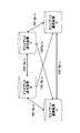
- FIG. 8 shows the amount of communication between client communication devices assumed as an example.
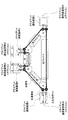
- FIG. 9 shows an example in which the band variable optical switching device 50 including the multi-optical signal output optical communication device 30 shown in the first embodiment is connected in a ring shape by an optical fiber 60. Yes.
- the client communication devices A, B, C, and D can communicate with each other by connecting the input / output port and the optical communication device 30.
- the bandwidth variable optical switching unit 50 is connected in a ring shape, but the network connection configuration of the present invention is not limited to the ring network, and the bandwidth variable optical switching device is a straight line. May be connected in a mesh, connected in a mesh, or a combination of straight lines, rings, and meshes, and can be applied to a network of any topology.
- one optical fiber 60 is drawn between the optical path switching devices, but this is shown by omitting a pair of upstream and downstream optical fibers.
- the optical signal a pair of upstream and downstream optical signals are omitted by using double-ended arrows.
- the input / output ports of the client communication devices A, B, C, and D are provided with means for adding information for identifying the destination to the client signal.
- the client communication device A will be described as an example.
- a client signal 100 Gb / s for the client communication device B From the input / output port of the client communication device A, a client signal 100 Gb / s for the client communication device B, a client signal 100 Gb / s for the client communication device C, and a client signal 200 Gb / s for the client communication device D Is output.
- the optical communication device 30A in which the variable bandwidth optical switching unit 50A is mounted distributes client signals for each destination, assigns management information, and then has a specified center optical frequency and is necessary for transferring each client signal. Depending on the capacity and transfer distance, it is converted into an optical signal having an appropriate baud rate, multi-value number, and number of carriers, wavelength-multiplexed, and input to the band variable optical switching unit 50A.
- Each optical signal is output to an output optical fiber corresponding to the assigned center optical frequency in the band variable optical switching unit 50A.
- the optical signal traveling from the optical communication device A to C is not processed by the client communication device B but is switched by the band variable optical switching unit 50B and reaches the band variable optical switching unit 50C. For this reason, the processing load of the client communication apparatus B does not increase.
- the number of client communication device interfaces and optical communication devices can be single or minimized, and low cost and low power consumption can be realized.
Landscapes
- Engineering & Computer Science (AREA)
- Computer Networks & Wireless Communication (AREA)
- Signal Processing (AREA)
- Optical Communication System (AREA)
Abstract
Description
前記入力されたクライアント信号を、宛先と宛先毎の通信容量に応じて複数に振り分ける振り分け手段と、
振り分けられたクライアント信号を中心光周波数が異なる複数の光信号に変換する電気光変換手段と、
前記複数の光信号を波長多重して出力する波長多重手段と、
波長多重された複数の波長多重光信号を波長毎に分離する手段と、
前記分離された光信号を電気信号に変換する光電気変換手段と、
前記光電気変換手段で変換された複数の電気信号を多重し、当該多重した電気信号を、電気信号のまま、もしくは光信号に変換してクライアント信号として出力する多重出力手段と、を有することを特徴とする光通信装置として構成される。
前記クライアント通信装置の入出力ポートは、宛先を識別する情報をクライアント信号に付与する手段を有し、
任意のクライアント通信装置の一つの入出力ポートは、前記光通信装置を介して、任意の複数のクライアント通信装置の前記入出力ポートに接続されるように構成される。
図4は、本発明の第1の実施の形態における光通信装置の基本機能ブロックを説明した図であり、図5は光信号周波数配置例を示す。
次に本発明の第2の実施の形態による光経路切替装置の構成を図6に示す。
次に本発明の第3の実施形態によるネットワークの構成を説明する。第3の実施形態によるネットワークは、複数の光経路切替装置が複数の光ファイバで接続された光波長多重ネットワークと、複数のクライアント通信装置から構成され、該クライアント通信装置が該光経路切替装置の挿入分岐ポートに備えられた光通信装置を介して接続され、任意のクライアント通信装置間が波長パスにより通信を行うネットワークの例である。
20 出力光ファイバ
30 光通信装置
31 挿入光ファイバ
32 分岐光ファイバ
50 帯域可変光切り替え部
60 光ファイバ
100 送信処理部
110 クライアント受信インタフェース
120 クライアント信号振り分け部
130 光レイヤ管理情報処理部
140 電気光変換部
150 光波長多重出力部
160 光ファイバ
200 受信処理部
210 光ファイバ
220 光分岐部
230 光電気変換部
240 光レイヤ管理情報処理部
250 クライアント信号集線部
260 クライアント送信インタフェース
Claims (4)
- クライアント通信装置から入力されたクライアント信号を、光ネットワークで転送するのに適した光信号に変換するとともに、受信した光信号をクライアント信号に変換する光通信装置であって、
前記入力されたクライアント信号を、宛先と宛先毎の通信容量に応じて複数に振り分ける振り分け手段と、
振り分けられたクライアント信号を中心光周波数が異なる複数の光信号に変換する電気光変換手段と、
前記複数の光信号を波長多重して出力する波長多重手段と、
波長多重された複数の波長多重光信号を波長毎に分離する手段と、
前記分離された光信号を電気信号に変換する光電気変換手段と、
前記光電気変換手段で変換された複数の電気信号を多重し、当該多重した電気信号を、電気信号のまま、もしくは光信号に変換してクライアント信号として出力する多重出力手段と、
を有することを特徴とする光通信装置。 - 前記電気光変換手段は、
前記光信号の伝送すべき距離と通信容量に応じて、必要最小限の占有スペクトル幅となるように変調方式を選択する手段を含む
請求項1記載の光通信装置。 - 波長多重信号を、多重、分離、挿入、分岐、方路振り分けする機能を有する光経路切替装置であって、
挿入分岐ポートが、請求項1又は2に記載の光通信装置への入出力ポートを具備し、多重、分離、挿入、分岐、方路振り分けする光周波数帯域幅は光信号の光スペクトル幅に応じて可変である
ことを特徴とする光経路切替装置。 - 複数の光経路切替装置が複数の光ファイバで接続された光波長多重ネットワークと、複数のクライアント通信装置から構成され、該クライアント通信装置が該光経路切替装置の挿入分岐ポートに備えられた光通信装置を介して接続され、任意のクライアント通信装置間が波長パスにより通信を行うネットワークであって、
前記クライアント通信装置の入出力ポートは、
宛先を識別する情報をクライアント信号に付与する手段を有し、
前記光経路切替装置は、
請求項3に記載の装置であり、
任意のクライアント通信装置の一つの入出力ポートは、請求項1又は2に記載の光通信装置を介して、任意の複数のクライアント通信装置の前記入出力ポートに接続される、
ことを特徴とするネットワーク。
Priority Applications (2)
| Application Number | Priority Date | Filing Date | Title |
|---|---|---|---|
| US14/009,264 US9479282B2 (en) | 2011-04-27 | 2012-04-26 | Optical communication apparatus, optical route switching apparatus and network |
| JP2013512450A JP5700877B2 (ja) | 2011-04-27 | 2012-04-26 | 光通信装置及び光経路切替装置及びネットワーク |
Applications Claiming Priority (2)
| Application Number | Priority Date | Filing Date | Title |
|---|---|---|---|
| JP2011099830 | 2011-04-27 | ||
| JP2011-099830 | 2011-04-27 |
Publications (1)
| Publication Number | Publication Date |
|---|---|
| WO2012147889A1 true WO2012147889A1 (ja) | 2012-11-01 |
Family
ID=47072404
Family Applications (1)
| Application Number | Title | Priority Date | Filing Date |
|---|---|---|---|
| PCT/JP2012/061285 Ceased WO2012147889A1 (ja) | 2011-04-27 | 2012-04-26 | 光通信装置及び光経路切替装置及びネットワーク |
Country Status (3)
| Country | Link |
|---|---|
| US (1) | US9479282B2 (ja) |
| JP (1) | JP5700877B2 (ja) |
| WO (1) | WO2012147889A1 (ja) |
Cited By (19)
| Publication number | Priority date | Publication date | Assignee | Title |
|---|---|---|---|---|
| JP2014217053A (ja) * | 2013-04-22 | 2014-11-17 | 富士通株式会社 | 可変的サブキャリアスペクトル割り当てを利用する光ネットワークにおけるクロストーク低減 |
| WO2015029091A1 (ja) * | 2013-08-30 | 2015-03-05 | 日本電気株式会社 | 光送信装置、光受信装置、光通信装置、光通信システム、及びこれらの制御方法 |
| JP2015220590A (ja) * | 2014-05-16 | 2015-12-07 | 富士通株式会社 | 光送信装置、光受信装置、及び、光伝送方法 |
| JP2016005193A (ja) * | 2014-06-18 | 2016-01-12 | 日本電信電話株式会社 | 光アクセスシステム、終端装置、宅内装置及び光アクセス方法 |
| JP2016509387A (ja) * | 2012-12-31 | 2016-03-24 | ゼットティーイー (ユーエスエー) インコーポレイテッド | 光伝送ネットワークのための適応データ伝送フォーマット |
| JP2016103760A (ja) * | 2014-11-28 | 2016-06-02 | 日本電信電話株式会社 | 光伝送装置、及び光信号伝送方法 |
| JP2016522599A (ja) * | 2013-04-07 | 2016-07-28 | ゼットティーイー コーポレーションZte Corporation | 可変グリッドラベルに基づくスペクトルリソース割当て方法及び装置 |
| JP2016213539A (ja) * | 2015-04-30 | 2016-12-15 | 日本電信電話株式会社 | 光伝送装置、光伝送方法、および、光伝送システム |
| WO2017033223A1 (ja) * | 2015-08-21 | 2017-03-02 | 三菱電機株式会社 | 光通信制御装置及び光通信制御方法 |
| JPWO2015033545A1 (ja) * | 2013-09-09 | 2017-03-02 | 日本電気株式会社 | 光ネットワーク制御装置および光ネットワーク制御方法 |
| EP3107227A4 (en) * | 2014-03-20 | 2018-02-28 | Nippon Telegraph and Telephone Corporation | Transport apparatus and transport method |
| JP2018088692A (ja) * | 2018-01-16 | 2018-06-07 | 日本電気株式会社 | 光送信装置、光受信装置、光通信装置、光通信システム、及びこれらの制御方法 |
| JP2018137507A (ja) * | 2017-02-20 | 2018-08-30 | 日本電信電話株式会社 | 光伝送システム及び光伝送方法 |
| JP2019193266A (ja) * | 2018-04-27 | 2019-10-31 | 富士通株式会社 | 変調方式及びサブキャリア数の制御を通じた光ネットワークについての到達距離拡大 |
| JP2019213212A (ja) * | 2018-01-16 | 2019-12-12 | 日本電気株式会社 | 光送信装置、光受信装置、光通信装置、光通信システム、及びこれらの制御方法 |
| JP2020078092A (ja) * | 2015-03-27 | 2020-05-21 | 日本電気株式会社 | 光ネットワークシステム、光ノード装置、および光ネットワーク制御方法 |
| JP2021158696A (ja) * | 2019-08-14 | 2021-10-07 | 日本電気株式会社 | 光送信装置、光受信装置、光通信装置、光通信システム、及びこれらの制御方法 |
| WO2023032200A1 (ja) * | 2021-09-06 | 2023-03-09 | 日本電信電話株式会社 | 通信システム、計算機、通信方法、および、プログラム |
| WO2024195049A1 (ja) * | 2023-03-22 | 2024-09-26 | 日本電信電話株式会社 | 光伝送システム、光伝送装置及び光伝送方法 |
Families Citing this family (15)
| Publication number | Priority date | Publication date | Assignee | Title |
|---|---|---|---|---|
| US9525490B2 (en) * | 2012-07-26 | 2016-12-20 | Aurrion, Inc. | Reconfigurable optical transmitter |
| US9088313B2 (en) * | 2013-02-16 | 2015-07-21 | Cable Television Laboratories, Inc. | Multiple-input multiple-output (MIMO) communication system |
| US9319257B2 (en) | 2013-02-16 | 2016-04-19 | Cable Television Laboratories, Inc. | Multiple-input multiple-output (MIMO) communication system |
| US9923621B2 (en) | 2013-02-16 | 2018-03-20 | Cable Television Laboratories, Inc. | Multiple-input multiple-output (MIMO) communication system |
| IN2013MU01980A (ja) * | 2013-06-10 | 2015-05-29 | Indian Inst Technology Bombay | |
| WO2015129472A1 (ja) * | 2014-02-28 | 2015-09-03 | 国立大学法人名古屋大学 | 光ネットワーク |
| CN108292952B (zh) * | 2015-11-26 | 2021-07-06 | 日本电信电话株式会社 | 通信系统以及故障检测方法 |
| KR102444403B1 (ko) * | 2016-02-23 | 2022-09-21 | 한국전자통신연구원 | 주파수 다중화 방식 광 전송 링크에서 if 반송파의 중심 주파수를 할당하는 광 신호 전송 시스템 및 그 방법 |
| KR102478167B1 (ko) * | 2016-11-29 | 2022-12-16 | 한국전자통신연구원 | 주파수 할당 방법 및 그 방법을 수행하는 전송 장치 |
| CN109600170B (zh) * | 2017-09-30 | 2023-01-24 | 中兴通讯股份有限公司 | 光模块及信号处理方法 |
| CN109802742B (zh) * | 2017-11-16 | 2020-05-19 | 华为技术有限公司 | 一种传输数据的方法、设备及系统 |
| CN107959528B (zh) * | 2017-12-13 | 2020-05-22 | 苏州大学 | 多芯光纤网络流量不对称业务传输的网络规划方法及网络 |
| JP6691155B2 (ja) * | 2018-02-27 | 2020-04-28 | ファナック株式会社 | 光通信システムおよび光送信モジュール |
| JPWO2023032127A1 (ja) * | 2021-09-02 | 2023-03-09 | ||
| US12237868B2 (en) * | 2022-02-02 | 2025-02-25 | Infinera Corporation | Service and power control orchestrator |
Citations (5)
| Publication number | Priority date | Publication date | Assignee | Title |
|---|---|---|---|---|
| JPS6359227A (ja) * | 1986-08-29 | 1988-03-15 | Nippon Telegr & Teleph Corp <Ntt> | パラレル伝送方式 |
| JPH1127231A (ja) * | 1997-06-30 | 1999-01-29 | Toshiba Corp | 無線通信システム |
| JP2009010679A (ja) * | 2007-06-28 | 2009-01-15 | Nippon Telegr & Teleph Corp <Ntt> | 光送信装置および光伝送システム |
| JP2010193184A (ja) * | 2009-02-18 | 2010-09-02 | Fujitsu Ltd | 光リングネットワークシステム及び光伝送装置 |
| WO2011030897A1 (ja) * | 2009-09-14 | 2011-03-17 | 日本電信電話株式会社 | 帯域可変通信方法、帯域可変通信装置、伝送帯域決定装置、伝送帯域決定方法、ノード装置、通信路設定システム、及び通信路設定方法 |
Family Cites Families (24)
| Publication number | Priority date | Publication date | Assignee | Title |
|---|---|---|---|---|
| JP3770767B2 (ja) * | 2000-02-17 | 2006-04-26 | 株式会社日立製作所 | トランスポンダ、波長多重伝送装置、波長多重伝送システムおよび情報通信装置 |
| JP3826653B2 (ja) * | 2000-02-25 | 2006-09-27 | Kddi株式会社 | 無線通信システムのサブキャリア割当方法 |
| US6288811B1 (en) * | 2000-10-17 | 2001-09-11 | Seneca Networks | WDM optical communication system with channels supporting multiple data formats |
| US20060210274A1 (en) * | 2001-02-06 | 2006-09-21 | Eyal Lichtman | Apparatus For and Method of MAC Based Transmission in WDM Optical Ring Networks |
| SE523986C2 (sv) * | 2001-03-09 | 2004-06-15 | Lumentis Ab | Optiskt WDM-Ringnät för flexibla förbindelser |
| JP3637965B2 (ja) * | 2001-11-22 | 2005-04-13 | 日本電気株式会社 | 無線通信システム |
| KR100493096B1 (ko) * | 2003-05-07 | 2005-06-02 | 삼성전자주식회사 | 고속 광 라우팅 장치 및 그 방법 |
| US8043854B2 (en) * | 2003-05-15 | 2011-10-25 | Waseda University | Method of decellularizing tissues |
| US20050063298A1 (en) * | 2003-09-02 | 2005-03-24 | Qualcomm Incorporated | Synchronization in a broadcast OFDM system using time division multiplexed pilots |
| US20050185959A1 (en) * | 2004-02-19 | 2005-08-25 | Fujitsu Limited | Photonic data storage network |
| JP4562443B2 (ja) * | 2004-07-15 | 2010-10-13 | 富士通株式会社 | 光伝送システム及び光伝送方法 |
| US7609966B2 (en) * | 2005-02-18 | 2009-10-27 | Fujitsu Limited | Method and system for time-sharing transmission frequencies in an optical network |
| KR20070112573A (ko) * | 2006-05-22 | 2007-11-27 | 삼성전자주식회사 | 다중반송파 통신시스템에서 자원 할당 장치 및 방법 |
| US20080181605A1 (en) * | 2007-01-30 | 2008-07-31 | Paparao Palacharla | Multi-degree optical node architectures |
| US20090186645A1 (en) * | 2008-01-17 | 2009-07-23 | Sangiamwong Jaturong | Multicarrier radio communication system, base station, radio relay station, mobile station, and multicarrier radio communication method |
| US7986878B2 (en) * | 2008-02-05 | 2011-07-26 | Opnext Subsystems, Inc. | Adjustable bit rate optical transmission using programmable signal modulation |
| JP5545212B2 (ja) * | 2008-05-26 | 2014-07-09 | 日本電気株式会社 | 波長パス通信ノード装置、波長パス通信制御方法、プログラム、および記録媒体 |
| WO2010003176A1 (en) * | 2008-07-07 | 2010-01-14 | Commonwealth Scientific And Industrial Resaerch Organisation | Parallel packet transmission |
| US8682175B2 (en) * | 2008-08-28 | 2014-03-25 | Cisco Technology, Inc. | Variable rate transponders for optical communication systems using digital electric filters |
| WO2010032844A1 (ja) * | 2008-09-19 | 2010-03-25 | 日本電信電話株式会社 | 帯域可変通信装置及び帯域可変通信方法 |
| US8218969B2 (en) * | 2009-03-18 | 2012-07-10 | Cisco Technology, Inc. | OFDM transponder interface with variable bit transfer rate in optical communications systems |
| US8909043B2 (en) * | 2011-02-04 | 2014-12-09 | Nec Laboratories America, Inc. | Routing, wavelength assignment, and spectrum allocation in wavelength convertible flexible optical wavelength-division multiplexing networks |
| US8611743B2 (en) * | 2011-02-22 | 2013-12-17 | Nec Laboratories America, Inc. | Optical-layer traffic grooming in flexible optical networks |
| US8873962B2 (en) * | 2011-03-30 | 2014-10-28 | Nec Laboratories America, Inc. | Method for traffic grooming, wavelength assignment and spectrum allocation |
-
2012
- 2012-04-26 WO PCT/JP2012/061285 patent/WO2012147889A1/ja not_active Ceased
- 2012-04-26 US US14/009,264 patent/US9479282B2/en active Active
- 2012-04-26 JP JP2013512450A patent/JP5700877B2/ja active Active
Patent Citations (5)
| Publication number | Priority date | Publication date | Assignee | Title |
|---|---|---|---|---|
| JPS6359227A (ja) * | 1986-08-29 | 1988-03-15 | Nippon Telegr & Teleph Corp <Ntt> | パラレル伝送方式 |
| JPH1127231A (ja) * | 1997-06-30 | 1999-01-29 | Toshiba Corp | 無線通信システム |
| JP2009010679A (ja) * | 2007-06-28 | 2009-01-15 | Nippon Telegr & Teleph Corp <Ntt> | 光送信装置および光伝送システム |
| JP2010193184A (ja) * | 2009-02-18 | 2010-09-02 | Fujitsu Ltd | 光リングネットワークシステム及び光伝送装置 |
| WO2011030897A1 (ja) * | 2009-09-14 | 2011-03-17 | 日本電信電話株式会社 | 帯域可変通信方法、帯域可変通信装置、伝送帯域決定装置、伝送帯域決定方法、ノード装置、通信路設定システム、及び通信路設定方法 |
Non-Patent Citations (1)
| Title |
|---|
| M. JINNO ET AL.: "Spectrum-Efficient and Scalable Elastic Optical Path Network: Architecture, Benefits, and Enabling Technologies", IEEE COMMUNICATIONS MAGAZINE, vol. 47, no. 11, November 2009 (2009-11-01), pages 66 - 73, XP011284156, DOI: doi:10.1109/MCOM.2009.5307468 * |
Cited By (41)
| Publication number | Priority date | Publication date | Assignee | Title |
|---|---|---|---|---|
| JP2016509387A (ja) * | 2012-12-31 | 2016-03-24 | ゼットティーイー (ユーエスエー) インコーポレイテッド | 光伝送ネットワークのための適応データ伝送フォーマット |
| JP2016522599A (ja) * | 2013-04-07 | 2016-07-28 | ゼットティーイー コーポレーションZte Corporation | 可変グリッドラベルに基づくスペクトルリソース割当て方法及び装置 |
| JP2014217053A (ja) * | 2013-04-22 | 2014-11-17 | 富士通株式会社 | 可変的サブキャリアスペクトル割り当てを利用する光ネットワークにおけるクロストーク低減 |
| US11637633B2 (en) | 2013-08-30 | 2023-04-25 | Nec Corporation | Optical transmission apparatus, optical reception apparatus, optical communications apparatus, optical communication system, and methods of controlling them |
| JPWO2015029091A1 (ja) * | 2013-08-30 | 2017-03-02 | 日本電気株式会社 | 光送信装置、光受信装置、光通信装置、光通信システム、及びこれらの制御方法 |
| WO2015029091A1 (ja) * | 2013-08-30 | 2015-03-05 | 日本電気株式会社 | 光送信装置、光受信装置、光通信装置、光通信システム、及びこれらの制御方法 |
| US10855377B2 (en) | 2013-08-30 | 2020-12-01 | Nec Corporation | Optical transmission apparatus, optical reception apparatus, optical communication apparatus, optical communication system, and methods of controlling them |
| US11936431B2 (en) | 2013-08-30 | 2024-03-19 | Nec Corporation | Optical transmission apparatus, optical reception apparatus, optical communication apparatus, optical communication system, and methods of controlling them |
| RU2634847C2 (ru) * | 2013-08-30 | 2017-11-07 | Нек Корпорейшн | Устройство оптической передачи, устройство оптического приема, устройство оптической связи, система оптической связи и способы управления ими |
| US11296793B2 (en) | 2013-08-30 | 2022-04-05 | Nec Corporation | Optical transmission apparatus, optical reception apparatus, optical communications apparatus, optical communication system, and methods of controlling them |
| JPWO2015033545A1 (ja) * | 2013-09-09 | 2017-03-02 | 日本電気株式会社 | 光ネットワーク制御装置および光ネットワーク制御方法 |
| US10231035B2 (en) | 2013-09-09 | 2019-03-12 | Nec Corporation | Optical network controller and optical network control method |
| EP3107227A4 (en) * | 2014-03-20 | 2018-02-28 | Nippon Telegraph and Telephone Corporation | Transport apparatus and transport method |
| US10122462B2 (en) | 2014-03-20 | 2018-11-06 | Nippon Telegraph And Telephone Corporation | Transport apparatus and transport method |
| JP2015220590A (ja) * | 2014-05-16 | 2015-12-07 | 富士通株式会社 | 光送信装置、光受信装置、及び、光伝送方法 |
| JP2016005193A (ja) * | 2014-06-18 | 2016-01-12 | 日本電信電話株式会社 | 光アクセスシステム、終端装置、宅内装置及び光アクセス方法 |
| JP2016103760A (ja) * | 2014-11-28 | 2016-06-02 | 日本電信電話株式会社 | 光伝送装置、及び光信号伝送方法 |
| JP2020078092A (ja) * | 2015-03-27 | 2020-05-21 | 日本電気株式会社 | 光ネットワークシステム、光ノード装置、および光ネットワーク制御方法 |
| US11652546B2 (en) | 2015-03-27 | 2023-05-16 | Nec Corporation | Optical network system, optical node device, and optical network control method |
| US12170539B2 (en) | 2015-03-27 | 2024-12-17 | Nec Corporation | Optical network system, optical node device, and optical network control method |
| JP7568031B2 (ja) | 2015-03-27 | 2024-10-16 | 日本電気株式会社 | 光ネットワークシステム |
| JP2023182832A (ja) * | 2015-03-27 | 2023-12-26 | 日本電気株式会社 | 光ネットワークシステム |
| US11201668B2 (en) | 2015-03-27 | 2021-12-14 | Nec Corporation | Optical network system, optical node device, and optical network control method |
| JP2016213539A (ja) * | 2015-04-30 | 2016-12-15 | 日本電信電話株式会社 | 光伝送装置、光伝送方法、および、光伝送システム |
| WO2017033223A1 (ja) * | 2015-08-21 | 2017-03-02 | 三菱電機株式会社 | 光通信制御装置及び光通信制御方法 |
| JPWO2017033223A1 (ja) * | 2015-08-21 | 2017-10-12 | 三菱電機株式会社 | 光通信制御装置及び光通信制御方法 |
| JP2018137507A (ja) * | 2017-02-20 | 2018-08-30 | 日本電信電話株式会社 | 光伝送システム及び光伝送方法 |
| JP2018088692A (ja) * | 2018-01-16 | 2018-06-07 | 日本電気株式会社 | 光送信装置、光受信装置、光通信装置、光通信システム、及びこれらの制御方法 |
| JP2019213212A (ja) * | 2018-01-16 | 2019-12-12 | 日本電気株式会社 | 光送信装置、光受信装置、光通信装置、光通信システム、及びこれらの制御方法 |
| JP2019193266A (ja) * | 2018-04-27 | 2019-10-31 | 富士通株式会社 | 変調方式及びサブキャリア数の制御を通じた光ネットワークについての到達距離拡大 |
| JP7287087B2 (ja) | 2018-04-27 | 2023-06-06 | 富士通株式会社 | 変調方式及びサブキャリア数の制御を通じた光ネットワークについての到達距離拡大 |
| JP2021158696A (ja) * | 2019-08-14 | 2021-10-07 | 日本電気株式会社 | 光送信装置、光受信装置、光通信装置、光通信システム、及びこれらの制御方法 |
| JP2023086981A (ja) * | 2019-08-14 | 2023-06-22 | 日本電気株式会社 | 光送信装置、光受信装置、光通信装置、光通信システム、及びこれらの制御方法 |
| JP7306433B2 (ja) | 2019-08-14 | 2023-07-11 | 日本電気株式会社 | 光送信装置、光受信装置、光通信装置、光通信システム、及びこれらの制御方法 |
| JP7599080B2 (ja) | 2019-08-14 | 2024-12-13 | アイピー ウェーブ ピーティーイー リミテッド | 光送信装置、光受信装置、光通信装置、光通信システム、及びこれらの制御方法 |
| WO2023032200A1 (ja) * | 2021-09-06 | 2023-03-09 | 日本電信電話株式会社 | 通信システム、計算機、通信方法、および、プログラム |
| US20240357008A1 (en) * | 2021-09-06 | 2024-10-24 | Nippon Telegraph And Telephone Corporation | Communication system, computer, communication method, and program |
| JPWO2023032200A1 (ja) * | 2021-09-06 | 2023-03-09 | ||
| JP7688291B2 (ja) | 2021-09-06 | 2025-06-04 | 日本電信電話株式会社 | 通信システム、計算機、通信方法、および、プログラム |
| US12363192B2 (en) | 2021-09-06 | 2025-07-15 | Nippon Telegraph And Telephone Corporation | Communication system, computing machine, communication method and program |
| WO2024195049A1 (ja) * | 2023-03-22 | 2024-09-26 | 日本電信電話株式会社 | 光伝送システム、光伝送装置及び光伝送方法 |
Also Published As
| Publication number | Publication date |
|---|---|
| US20140270776A1 (en) | 2014-09-18 |
| US9479282B2 (en) | 2016-10-25 |
| JP5700877B2 (ja) | 2015-04-15 |
| JPWO2012147889A1 (ja) | 2014-07-28 |
Similar Documents
| Publication | Publication Date | Title |
|---|---|---|
| JP5700877B2 (ja) | 光通信装置及び光経路切替装置及びネットワーク | |
| Jinno | Elastic optical networking: roles and benefits in beyond 100-Gb/s era | |
| US9124369B2 (en) | Multi-direction variable optical transceiver | |
| Saleh et al. | Evolution toward the next-generation core optical network | |
| US8861977B2 (en) | Multiplexer and modulation arrangements for multi-carrier optical modems | |
| Shen et al. | Spectrum-efficient and agile CO-OFDM optical transport networks: architecture, design, and operation | |
| CN102833029B (zh) | 用于多载波光调制解调器的复用器和调制装置 | |
| Kozicki et al. | Filtering characteristics of highly-spectrum efficient spectrum-sliced elastic optical path (SLICE) network | |
| JP2015220590A (ja) | 光送信装置、光受信装置、及び、光伝送方法 | |
| JP2014150544A (ja) | Ofdmを使用する光伝送方法および装置 | |
| US9560429B2 (en) | Optical switch | |
| Takara et al. | Spectrally-efficient elastic optical path networks toward 1 Tbps era | |
| WO2011047715A1 (en) | Optical transport switching node with framer | |
| Tremblay et al. | Agile filterless optical networking | |
| JP5775012B2 (ja) | 光識別再生装置及び光経路切り替え装置 | |
| US9693123B2 (en) | Optical switch | |
| Nooruzzaman et al. | Low-cost hybrid ROADM architectures for scalable C/DWDM metro networks | |
| Papapavlou et al. | Scalability analysis and switching hardware requirements for a novel multi-granular SDM/UWB 10 Pbps optical node | |
| Jinno et al. | Elastic optical path network architecture: Framework for spectrally-efficient and scalable future optical networks | |
| Jinno et al. | Elastic optical path networking: Enhancing network capacity and disaster survivability toward 1 Tbps era | |
| US10735126B1 (en) | Splitter-based colorless-directionless-contentionless reconfigurable optical add/drop multiplexer | |
| Jinno et al. | Introducing elasticity and adaptation into the optical domain toward more efficient and scalable optical transport networks | |
| Zami | Multiflow application for WDM networks with multicarrier transponders serving superchannels in contentionless OXCS | |
| Gumaste et al. | Reach optimized architecture for multi-rate transport system (ROAMTS): One size does not fit all | |
| Bohn et al. | Elastic optical networks: The vision of the ICT project IDEALIST |
Legal Events
| Date | Code | Title | Description |
|---|---|---|---|
| 121 | Ep: the epo has been informed by wipo that ep was designated in this application |
Ref document number: 12777646 Country of ref document: EP Kind code of ref document: A1 |
|
| ENP | Entry into the national phase |
Ref document number: 2013512450 Country of ref document: JP Kind code of ref document: A |
|
| WWE | Wipo information: entry into national phase |
Ref document number: 14009264 Country of ref document: US |
|
| NENP | Non-entry into the national phase |
Ref country code: DE |
|
| 122 | Ep: pct application non-entry in european phase |
Ref document number: 12777646 Country of ref document: EP Kind code of ref document: A1 |