WO2012147934A1 - Couteau médical - Google Patents
Couteau médical Download PDFInfo
- Publication number
- WO2012147934A1 WO2012147934A1 PCT/JP2012/061406 JP2012061406W WO2012147934A1 WO 2012147934 A1 WO2012147934 A1 WO 2012147934A1 JP 2012061406 W JP2012061406 W JP 2012061406W WO 2012147934 A1 WO2012147934 A1 WO 2012147934A1
- Authority
- WO
- WIPO (PCT)
- Prior art keywords
- blade
- width direction
- edge
- end portion
- distal end
- Prior art date
- Legal status (The legal status is an assumption and is not a legal conclusion. Google has not performed a legal analysis and makes no representation as to the accuracy of the status listed.)
- Ceased
Links
Images




Classifications
-
- A—HUMAN NECESSITIES
- A61—MEDICAL OR VETERINARY SCIENCE; HYGIENE
- A61B—DIAGNOSIS; SURGERY; IDENTIFICATION
- A61B17/00—Surgical instruments, devices or methods
- A61B17/32—Surgical cutting instruments
- A61B17/3209—Incision instruments
- A61B17/3211—Surgical scalpels, knives; Accessories therefor
-
- A—HUMAN NECESSITIES
- A61—MEDICAL OR VETERINARY SCIENCE; HYGIENE
- A61F—FILTERS IMPLANTABLE INTO BLOOD VESSELS; PROSTHESES; DEVICES PROVIDING PATENCY TO, OR PREVENTING COLLAPSING OF, TUBULAR STRUCTURES OF THE BODY, e.g. STENTS; ORTHOPAEDIC, NURSING OR CONTRACEPTIVE DEVICES; FOMENTATION; TREATMENT OR PROTECTION OF EYES OR EARS; BANDAGES, DRESSINGS OR ABSORBENT PADS; FIRST-AID KITS
- A61F9/00—Methods or devices for treatment of the eyes; Devices for putting in contact-lenses; Devices to correct squinting; Apparatus to guide the blind; Protective devices for the eyes, carried on the body or in the hand
- A61F9/007—Methods or devices for eye surgery
- A61F9/013—Instruments for compensation of ocular refraction ; Instruments for use in cornea removal, for reshaping or performing incisions in the cornea
- A61F9/0133—Knives or scalpels specially adapted therefor
-
- F—MECHANICAL ENGINEERING; LIGHTING; HEATING; WEAPONS; BLASTING
- F04—POSITIVE - DISPLACEMENT MACHINES FOR LIQUIDS; PUMPS FOR LIQUIDS OR ELASTIC FLUIDS
- F04C—ROTARY-PISTON, OR OSCILLATING-PISTON, POSITIVE-DISPLACEMENT MACHINES FOR LIQUIDS; ROTARY-PISTON, OR OSCILLATING-PISTON, POSITIVE-DISPLACEMENT PUMPS
- F04C2270/00—Control; Monitoring or safety arrangements
- F04C2270/04—Force
- F04C2270/042—Force radial
- F04C2270/0421—Controlled or regulated
Definitions
- the present invention relates to a medical knife used as various surgical cutting tools for incising a living tissue such as an eyeball in, for example, cataract surgery.
- a corneal incision method and a keratotomy method are well known.
- an operator forms an incision in the cornea with a single knife such as a slit knife or a clear conical knife and perforates the anterior chamber.
- a single knife such as a slit knife or a clear conical knife
- the operator cuts the conjunctiva, then cuts the sclera through a half-layer with a straight knife, then extends the incision to the cornea with a crescent knife, and finally punctures the anterior chamber with a slit knife.
- a transconjunctival / corneal one-sided incision method is known.
- the surgeon is about 0.5 mm outward from the ring portion 31, for example, about the eyebrow side.
- a knife is inserted into the conjunctiva 32 at a position of 0.5 mm and cut into the sclera 33 as it is to enter the cornea 34, and then pierced into the anterior chamber 35 with the knife.
- the incision is covered and protected by the upper eyelid after the operation, so that endophthalmitis due to infection is less likely to occur.
- the operator performs the sensation of pushing the knife up along the curve of the cornea 34 and moving it upward, ie, outward.
- the inside of the incision 37 The incision line 37a tends to be substantially straight.
- the operator rounds up the conjunctiva 32 toward the cornea 34 at both side edges of the wound 37b (outward incision line) of the incision 37, and allows the perfusate to escape to the side of the wound 37b (outward incision line).
- the knife moves along the movement trajectory 38a along the direction of the arrow P that penetrates the conjunctiva 32 and the direction of the arrow Q that enters the cornea 34 from the sclera 33 in the cross section of the eyeball shown in FIG.
- the movement trajectory 38b and the movement trajectory 38c along the direction of the arrow R drilled into the anterior chamber 35 move along the substantially S-shaped movement trajectory 38 while sequentially changing the approach direction.
- the advantages and disadvantages of these incisions are shown in Table 1.
- the path of the incision 37 is formed in a substantially crank shape or a substantially S shape, so that the incision 37 is closed without being sewn. Excellent self-closing properties.
- a medical knife used when performing a cataract operation by such a transconjunctival / corneal keratotomy for example, a bevel-up type slit knife, or FIG.
- a handle is provided on the base end portion of the blade plate having the blade portion at the distal end portion.
- a knife is used in which the extending direction of the grip portion provided on the handle and the extending direction of the blade plate intersect each other.
- the blade portion of the blade plate is on the upper side, which is the extending direction of the handle grip portion, on the upper and lower sides in the thickness direction of the blade plate.
- It has a formed front part and a back part formed on the lower side opposite to the extending direction of the handle gripping part.
- the distance in the thickness direction is reduced from the center in the width direction of the blade plate to both outer edges in the width direction.
- a blade edge that extends from the distal end portion to the proximal end portion of the blade portion is formed at the outer edge where the blade surface of the front portion and the blade surface of the back portion intersect each other.
- the surgeon is shown in FIG.
- the anterior chamber 35 is perforated by a knife with a moving locus 38 c along the direction of the arrow R.
- the front portion of the blade portion and the back portion of the blade portion are provided with the blade portion according to the shape of the front portion and the back portion. The upward force that pushes up and the downward force that pushes down work.
- the blade portion Depending on the balance between the upward force and the downward force, the blade portion enters the anterior chamber 35 while being translated upward or downward.
- the incision line 37c tends to be a convex chevron as shown in FIG. 4 (c) due to the sharp edges where the blade edges in the width direction intersect each other.
- the incision line 37d tends to be V-shaped as shown in FIG. In either case, the inner incision lines 37c and 37d are liable to be displaced from each other, which may impair the self-closing property.
- both the blade surfaces in the width direction of the front portion gradually widen as the distance between the opposite sides with respect to the blade edge moves from the tip portion toward the base end portion. It is formed as follows. As shown in FIG. 2 in the drawing of Patent Document 1, the widths of the two blade surfaces in the width direction of the back portion are such that the distance between the opposite sides to the blade edge is the same in the entire blade edge extending from the distal end portion to the proximal end portion of the blade edge. Is formed. As shown in FIG.
- the widths of the opposite sides of the widthwise direction of the back portion of the back portion with respect to the blade edge are directed from the distal end portion to the proximal end portion in the same manner as the two blade surfaces in the width direction of the front portion. It is formed so as to spread gradually.
- the area of both blade surfaces in the width direction at the front portion of the blade portion is larger on the proximal side than the tip portion. Therefore, as described above, when the downward force that pushes down the blade portion is applied to the front portion, the downward force applied to the base end portion of the front portion is less than the downward force applied to the front end portion of the front portion. Also grows. The difference in the downward force tends to cause a rotational moment in a direction in which the base end of the blade is pushed down and the tip of the blade is pushed up. Further, the area of both blade surfaces in the width direction at the back of the blade portion is larger on the proximal end side than on the distal end side.
- the object of the present invention is to improve the shape of the blade portion of a medical knife so that, for example, when performing a cataract operation by transconjunctival / corneal one-sided incision, a substantially S-shaped incision with excellent self-closing properties is easily obtained. There is in forming.
- the medical knife of the first to sixth aspects of the present invention has the following common configuration.
- the medical knife includes a handle having a grip portion and extending in one direction, a blade plate extending from the handle so as to intersect the handle, and having a distal end portion and a proximal end portion, and a distal end of the blade plate A blade portion formed on the portion.
- the blade portion of the blade plate is opposite to the extending direction of the handle gripping portion and the front portion formed on the upper side, which is the extending direction of the handle gripping portion, of the upper and lower sides in the thickness direction of the blade plate. And a back portion formed on a lower side.
- the distance in the thickness direction is reduced from the center portion in the width direction of the blade plate to both outer edges in the width direction.
- an inclined blade surface is formed, and a blade edge extending from the distal end portion of the blade portion toward the proximal end portion is formed at the outer edge where the blade surface of the front portion and the blade surface of the back portion intersect each other.
- the two blade surfaces in the width direction of the front portion and the two blade surfaces in the width direction of the back portion of the blade portion are opposite to the blade edge. Is formed so as to gradually widen from one end to the other of the tip end portion and the base end portion. That is, the two blade surfaces in the width direction of the back portion are formed so as to gradually spread from the distal end portion toward the proximal end portion as shown in the first embodiment of FIGS. Alternatively, the two blade surfaces in the width direction of the back portion are formed so as to gradually expand from the base end portion toward the tip end portion as shown in the second embodiment of FIGS.
- the distance between the opposite sides of the tip edge to the edge of the edge and the distance between the opposite edges of the edge to the edge of the edge of the entire edge extending from the tip of the edge to the base end is the same. It is formed to become.
- the same includes substantially the same.
- the two blade surfaces in the width direction of the front portion and the two blade surfaces in the width direction of the back portion of the blade portion are opposite to the blade edge. Is formed so as to gradually widen from one end to the other of the tip end portion and the base end portion.
- the two blade surfaces in the width direction of the front portion are opposite from the direction in which the distance between the two blade surfaces in the width direction of the back portion is widened with respect to the blade edge. It is formed so that it gradually narrows as it goes to. That is, as shown in the third embodiment in FIGS.
- the both blade surfaces in the width direction of the back portion are formed so as to gradually spread from the tip portion toward the base end portion, and the width direction of the front portion.
- the two blade surfaces are formed so as to gradually spread from the proximal end portion toward the distal end portion, or, as shown in the fourth embodiment in FIGS. 9 to 10, the both blade surfaces in the width direction of the back portion are formed from the proximal end portion to the distal end portion.
- the two blade surfaces in the width direction of the front portion are formed so as to gradually spread from the distal end portion toward the proximal end portion.
- the width of the back portion of the blade portion in the width direction of the front portion and the blade surface in the width direction of the back portion of the blade portion is such that the distance between the opposite sides of the entire edge of the blade edge extending from the distal end to the proximal end of the edge of the blade edge with respect to the edge of the distal end is the same as the distance between the opposite sides with respect to the edge of the proximal edge. Is formed.
- the two blade surfaces in the width direction of the front portion are formed such that the distance between the opposite sides with respect to the edge of the blade gradually increases as it goes from the base end portion to the tip end portion.
- the same includes substantially the same.
- the third mode corresponding to the third embodiment shown in FIGS. 7 to 8, and the fifth mode shown in FIGS.
- the operator when performing a cataract operation by transconjunctival / corneal one-sided incision, the operator moves the blade part from the vicinity of the annulus to the anterior chamber through the conjunctiva, sclera and cornea. Push forward along the trajectory. At this time, the surgeon tends to generate a rotational moment that pushes up the proximal end of the blade and pushes down the distal end of the blade.
- a character-shaped incision can be easily formed, and the incision line of the incision is not chevron-shaped and is easily formed in a single straight line.
- cataract surgery using a transconjunctival / corneal keratotomy is performed.
- the surgeon pushes the blade portion from the vicinity of the limbus through the conjunctiva, sclera and cornea to the anterior chamber with a substantially S-shaped movement locus.
- it is easy to generate a rotational moment that pushes up the distal end of the blade and pushes down the proximal end of the blade.
- the two blade surfaces in the width direction of the front portion are the entire edge of the blade edge extending from the distal end portion to the proximal end portion of the blade edge. Are formed so that the distance between the opposite sides is the same.
- the same includes substantially the same.
- it in the first mode corresponding to the first embodiment shown in FIGS. 1 to 4, it is easy to generate a rotational moment that pushes up the base end of the blade and pushes down the tip of the blade.
- the first mode corresponding to the second embodiment shown in FIGS. 5 to 6 it is easy to generate a rotational moment in a direction in which the tip end portion of the blade portion is pushed up and the base end portion of the blade portion is pushed down.
- the two blade surfaces in the width direction of the back portion are the entire edge of the blade edge extending from the distal end portion to the proximal end portion of the blade edge. Are formed so that the distance between the opposite sides is the same.
- the same includes substantially the same. In this case, a rotational moment in a direction D that pushes up the base end of the blade 6 and pushes down the tip of the blade 6 is likely to occur.
- the pointed edge and the double-edged blade in which the blade edges of the double-edged blade surfaces intersect each other respectively.
- a boundary edge between the two blade surfaces in the width direction is formed between the top edges where the opposite sides of the surface intersect each other, and an intermediate surface is formed between the opposite sides of the two blade surfaces in the width direction.
- both edge edges in the width direction of the blade portion are extended from the tip to the end.
- the maximum width direction interval is set between the end points of both edge edges in the width direction.
- Marks are provided on a line segment that connects the ends of both edge edges in the width direction with each other or on the base end side or the tip end side of the line segment.
- the distance between the mark and the tip and the distance in the width direction between the ends of both edge edges in the width direction are set to be the same.
- the same includes substantially the same.
- the surgeon pushes the blade from the vicinity of the limbus through the conjunctiva, sclera and cornea to the anterior chamber with a substantially S-shaped movement trajectory.
- the mark reaches the outer incision line of the incision, the tip of the blade begins to enter the anterior chamber.
- the shape of the incision formed between the inner incision line and the outer incision line becomes close to a square, and the self-closing property of the incision can be improved.
- both edge edges in the width direction of the blade portion are extended from the tip to the end.
- the maximum width direction interval is set between the end points of both edge edges in the width direction.
- Marks are provided on a line segment that connects the ends of both edge edges in the width direction with each other or on the base end side or the tip end side of the line segment.
- the distance between the mark and the tip and the distance in the width direction between the ends of both edge edges in the width direction are set to be the same.
- the same includes substantially the same.
- the surgeon pushes the blade from the vicinity of the limbus through the conjunctiva, sclera and cornea to the anterior chamber with a substantially S-shaped movement trajectory.
- the mark reaches the outer incision line of the incision, the tip of the blade begins to enter the anterior chamber.
- the shape of the incision formed between the inner incision line and the outer incision line becomes close to a square, and the self-closing property of the incision can be improved.
- the blade plate is bent toward the front portion of the blade portion with respect to the handle.
- the length of the blade plate extending from the distal end portion to the proximal end portion of the blade portion is set to be not less than 10 times and not more than 50 times the thickness of the blade plate.
- the opening angle between both blade edges in the width direction in the blade portion is 60 degrees or more and 120 degrees or less, preferably 60 degrees or more. It is set to 90 degrees or less.
- the opening angle between the blade edges in the width direction is made obtuse, and the incision line of the incision is not formed in a mountain shape but is easily formed in a single straight line.
- the intermediate surface of the front portion of the blade portion and the intermediate surface of the back portion of the blade portion may be formed in parallel to each other. Accordingly, when performing a cataract operation by transconjunctival / corneal corneal incision, the operator moves the blade portion from the vicinity of the annulus 31 to the anterior chamber through the conjunctiva, the sclera, and the cornea to a substantially S-shaped movement locus 38. Can be pushed along with less resistance.
- the width direction with respect to the thickness direction surface passing through the boundary edge between both blade surfaces in the width direction may be formed symmetrically.
- the blade surface of the front portion of the blade portion and the blade surface of the back portion of the blade portion may have different shapes. This makes it easy to generate a rotational moment that pushes up the base end of the blade and pushes down the tip of the blade, or a rotational moment that pushes up the tip of the blade and pushes down the base of the blade. Become.
- the inclination angle ⁇ formed by the blade surface of the front portion of the blade portion with respect to the surface passing through both edge edges in the width direction, and the width One of the inclination angles formed by the blade surface of the back portion of the blade portion with respect to the surface passing through both edge edges in the direction may be set larger than the other. This makes it easy to generate a rotational moment that pushes up the base end of the blade and pushes down the tip of the blade, or a rotational moment that pushes up the tip of the blade and pushes down the base of the blade. Become.
- one of the inclination angle formed by the blade surface of the front portion of the blade portion and the inclination angle formed by the blade surface 10 of the back portion of the blade portion may be set to be equal to or less than half of the other.
- the blade plate is bent toward the front side of the blade portion with respect to the handle, and extends from the distal end portion to the proximal end portion of the blade portion.
- the length of the blade plate may be set to 10 to 50 times the thickness of the blade plate.
- the opening angle between both blade edges in the width direction is 60 degrees or more and 120 degrees or less, preferably 60 degrees or more. It is set to 90 degrees or less.
- the opening angle between the blade edges 11 in the width direction is made obtuse, and the incision line of the incision is not formed in a mountain shape but is easily formed in a single straight line.
- the pointed edge and the double edge in the width direction where the edge edges of the two blade surfaces in the width direction intersect with each other, respectively.
- a boundary edge between the two blade surfaces in the width direction is formed between the top edges where the opposite sides of the surface intersect with each other, and an intermediate surface is formed between the opposite sides of the two blade surfaces in the width direction.
- the distance between opposite sides of the blade edge in the width direction with respect to the blade edge may be set to be larger than the distance between the opposite edge with respect to the edge of the blade in the width direction of the front portion of the blade portion.
- the surgeon pushes the blade from the vicinity of the annulus to the anterior chamber through the conjunctiva, sclera and cornea along a substantially S-shaped trajectory. Not only is the rotation moment of the blade portion pushed up and the tip portion of the blade portion pushed down, or the moment of rotation of the blade portion 6 pushed up and the base portion of the blade portion 6 pushed down. In terms of occurrence, the two blade surfaces in the width direction at the back of the blade portion are more likely to affect the two blade surfaces in the width direction at the front portion of the blade portion.
- the present invention improves the shape of the blade of a medical knife so that, for example, when performing cataract surgery using a transconjunctival / corneal one-sided incision method, an approximately S-shaped incision 37 having excellent self-closing properties can be easily obtained. Can be formed.
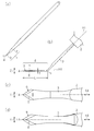
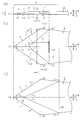
- FIG. 1 which shows the back side of a blade part It is the elements on larger scale of (d).
- 2A is a cross-sectional view taken along the line A1-A1 of FIG. 2B
- FIG. 2B is a cross-sectional view taken along the line A2-A2 of FIG. 2B
- FIG. 1 is the elements on larger scale of (d).
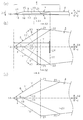
- A3 line partial sectional view is a partial cross-sectional view of an eyeball for explaining the method of using a medical knife by transconjunctival and cornea one-sided incision method, and (b), (c), and (d) are the eyeball rings respectively. It is a partial surface view of a part.
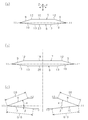
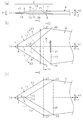
- (A) is a partial enlarged front view of a blade part in the medical knife concerning 2nd Embodiment of this invention, (b) is the elements on larger scale which show the front side of a blade part similarly, (c) is the same It is a partial expanded bottom view which shows the back side of a blade part.
- 5A is a cross-sectional view taken along line B1-B1 of FIG. 5B, FIG.
- FIG. 5B is a cross-sectional view taken along line B2-B2 of FIG. 5B
- FIG. 5C is a cross-sectional view taken along line B3-B2 of FIG. It is a B3 line partial sectional view.
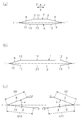
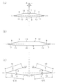
- (A) is the elements on larger scale of the blade part in the medical knife concerning 3rd Embodiment of this invention
- (b) is the elements on larger scale which similarly show the front side of a blade part
- (c) is the same It is a partial expanded bottom view which shows the back side of a blade part.
- 7A is a sectional view taken along line C1-C1 in FIG. 7B
- FIG. 7B is a sectional view taken along line C2-C2 in FIG. 7B
- FIG. 7C is a sectional view taken along line C3-C2 in FIG. It is a C3 partial fragmentary sectional view.
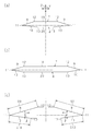
- (A) is a partial enlarged front view of a blade part in the medical knife concerning 4th Embodiment of this invention,
- (b) is the elements on larger scale which show the front side of a blade part similarly,
- (c) is the same It is a partial expanded bottom view which shows the back side of a blade part.
- 9A is a sectional view taken along line D1-D1 in FIG. 9B
- FIG. 9B is a sectional view taken along line D2-D2 in FIG. 9B
- FIG. 9C is a sectional view taken along line D3-D2 in FIG. It is a D3 line fragmentary sectional view.
- FIG. 11A is a cross-sectional view taken along line E1-E1 in FIG. 11B
- FIG. 11B is a cross-sectional view taken along line E2-E2 in FIG. 11B
- FIG. 11C is a cross-sectional view taken along line E3- in FIG. It is an E3 line partial sectional view.
- the medical knife shown in FIG. 1 (a) is mainly used as various surgical cutting tools for incising a living tissue such as an eyeball in cataract surgery.
- the medical knife includes a handle 1 having a grip portion 2 made of a synthetic resin and a support plate 3 made of a metal such as stainless steel, and a blade plate 4 extending from the handle 1.
- the blade plate 4 is made of a metal such as stainless steel.
- the support plate 3 is inserted into the distal end portion of the grip portion 2, and their extending directions X1 coincide with each other.
- the blade plate 4 extends continuously and integrally from the support plate 3, and is bent with respect to the support plate 3 at a bent portion 5 provided at a base end portion of the blade plate 4.
- the extending direction X1 of the grip portion 2 and the support plate 3 in the handle 1 and the extending direction X4 of the blade plate 4 intersect each other at 45 degrees.
- a blade 6 is provided at the tip of the blade plate 4.
- the blade portion 6 of the blade plate 4 is a front portion formed on the upper side which is the extending direction of the handle 1 and the support plate 3, that is, the bending direction, of the upper and lower sides in the thickness direction Z of the blade plate 4. 7 and a back portion 8 formed on the lower side opposite to the extending direction of the grip portion 2 of the handle 1 and the support plate 3.
- the front part 7 and the back part 8 of the blade part 6 intersect in the thickness direction Z.
- the flat blade surfaces 9 are inclined so as to narrow the distance in the thickness direction Z from the center in the width direction Y of the blade plate 4 to both outer edges in the width direction Y, respectively.
- 10 are formed.
- a blade edge 11 that extends linearly from the distal end portion to the proximal end portion of the blade portion 6 is formed at the outer edge where the blade surface 9 of the front portion 7 and the blade surface 10 of the back portion 8 intersect each other.
- opposite sides 12 and 13 with respect to the blade edge 11 extend linearly from the distal end portion of the blade portion 6 toward the proximal end portion.
- the tip edges 14 (tips of the blade plate 4 and the blade portion 6) where the blade edges 11 of both the blade surfaces 9 and 10 in the width direction Y intersect each other in a V shape.
- the top edges 15 and 16 where the opposite sides 12 and 13 of the both blade surfaces 9 and 10 in the width direction Y intersect each other in a V shape are the boundary edges between the both blade surfaces 9 and 10 in the width direction Y 17 and 18 are linearly formed.
- Flat intermediate surfaces 19 and 20 are formed between opposite sides 12 and 13 of both blade surfaces 9 and 10 in the width direction Y.
- Each of the intermediate surfaces 19 and 20 has an isosceles triangle shape connecting the top ends 15 and 16 of the opposite sides 12 and 13 and the end points 22 and 23 of the opposite sides 12 and 13 to each other.
- the base end portion of the blade portion 6 is between the end portions 23 that are far from the tip end 14 among the line segment portion that connects the end points 22 of the opposite sides 12 and the line segment portion that connects the end points 23 of the opposite sides 13 to each other. This corresponds to the line segment.
- the intermediate surface 19 of the front portion 7 of the blade portion 6 and the intermediate surface 20 of the back portion 8 of the blade portion 6 are formed in parallel to each other.
- Both the blade edges 11 in the width direction Y are extended so as to gradually incline from the back part 8 toward the front part 7 toward the terminal end 21 from the pointed end 14.
- the both blade surfaces 9, 10 in the width direction Y with respect to the thickness direction surface passing through the boundary edges 17, 18 between the both blade surfaces 9, 10 in the width direction Y are respectively It is formed symmetrically.
- Both the blade surfaces 10 in the width direction Y of the back portion 8 in the blade portion 6 are formed such that the gap G10 of the opposite side 13 with respect to the blade edge 11 gradually increases from the distal end portion to the proximal end portion of the blade portion 6.
- interval G10 it can set to the range of 0.2 mm or more and 1.5 mm or less in the front-end
- the gap G10 is set to 0.44 mm at the distal end portion of the blade portion 6, and is set to 0.63 mm at the proximal end portion of the blade portion 6, for example.
- the two blade surfaces 9 in the width direction Y of the front portion 7 of the blade portion 6 are such that the distance G9 between the opposite sides 12 with respect to the blade edge 11 is substantially the same for the entire blade edge 11 extending from the distal end portion to the proximal end portion of the blade portion 6. Is formed.
- interval G9 it is preferable to set to the range of 0.2 mm or more and 1.5 mm or less both in the front-end
- the gap G9 is set to 0.42 mm at the distal end portion of the blade portion 6 and is set to 0.38 mm at the proximal end portion of the blade portion 6. Therefore, the blade surface 9 of the front portion 7 of the blade portion 6 and the blade surface 10 of the back portion 8 of the blade portion 6 have different shapes.
- the inclination angle ⁇ formed by the blade surface 9 of the front portion 7 of the blade portion 6 with respect to the surface passing through both blade edges 11 in the width direction Y is the back of the blade portion 6 with respect to this surface.
- the inclination angle ⁇ is set to be larger than the inclination angle ⁇ formed by the blade surface 10 of the portion 8, and the inclination angle ⁇ is set to be equal to or less than half of the inclination angle ⁇ .
- the inclination angle ⁇ is set in the range of 10 degrees to 60 degrees, preferably in the range of 10 degrees to 30 degrees, and the inclination angle ⁇ is in the range of 3 degrees to 30 degrees, preferably in the range of 3 degrees to 10 degrees.
- the inclination angle ⁇ is set to 20 degrees
- the inclination angle ⁇ is set to 6 degrees.
- the opening angle ⁇ between the two blade edges 11 in the width direction Y in the blade portion 6 is in the range of 60 degrees to 120 degrees, preferably 60 degrees to 90 degrees. Is set in the range. In the present embodiment, the opening angle ⁇ is set to 67 degrees, for example.
- the length L of the blade plate 4 extending from the sharp tip 14 of the blade portion 6 to the bent portion 5 of the blade plate 4, the intermediate surface 19 of the front portion 7 of the blade portion 6 and the blade portion 6. It is preferable to set in the range of 10 times to 50 times the thickness T of the blade plate 4 between the back part 8 and the intermediate surface 20.
- the length L is set to, for example, 6 mm within a range of 2.5 mm to 10 mm
- the thickness T is set to, for example, 0.2 mm within a range of 0.05 mm to 1.0 mm.
- the two edge edges 11 in the width direction Y of the blade portion 6 form a maximum width direction interval W between the terminal ends 21 of the edge edges 11, and the width thereof.
- a linear mark 24 is attached to the base end portion of the blade portion 6 rather than the line segment connecting the terminal ends 21 of the blade edge 11 in the direction Y to each other.
- the distance M between the mark 24 and the tip 14 and the width direction interval W between the terminal ends 21 of the two blade edges 11 in the width direction Y are set to be substantially the same.
- the interval W in the width direction and the distance M are preferably set in the range of 1.0 mm or more and 5.0 mm or less, and in this embodiment, for example, 2.4 mm.
- the linear mark 24 may be attached
- the blade portion 6 moves along the movement locus 38a along the direction of the arrow P that penetrates the conjunctiva 32 and moves along the direction of the arrow Q that enters the cornea 34 from the sclera 33.
- the trajectory 38b and the movement trajectory 38c along the direction of the arrow R drilled into the anterior chamber 35 are moved along the substantially S-shaped movement trajectory 38 while sequentially changing the approach direction.
- the area of both blade surfaces 10 in the width direction Y at the back portion 8 of the blade portion 6 is larger on the proximal end side than on the distal end side of the blade portion 6.
- the movement locus 38b, 38c When moving to the movement locus 38c along the direction of the arrow R drilled into the edge, the movement locus 38b, 38c is moved by the rotational moment in the direction D that pushes up the proximal end portion of the blade portion 6 and pushes down the distal end portion of the blade portion 6. It is easy to make changes.
- Both the blade surfaces 10 in the width direction Y of the back portion 8 in the blade portion 6 are different from the back portion 8 in the blade portion 6 of the first embodiment, and the distance G10 of the opposite side 13 to the blade edge 11 is the blade portion of the first embodiment.
- 6 is formed so as to gradually spread from the base end portion of the blade portion 6 toward the tip portion in the opposite direction to the back portion 8.
- the base end portion of the blade portion 6 is located at a position far from the apex 14 among a line segment portion connecting the end points 22 of the opposite sides 12 and a line segment portion connecting the end points 23 of the opposite sides 13 to each other. This corresponds to the line segment between the end points 22.
- interval G10 can set to the range of 0.2 mm or more and 1.5 mm or less at the base end part of the blade part 6, and can set to the range of 0.3 mm or more and 2.0 mm or less at the front-end
- the gap G10 is set to 0.63 mm at the distal end portion of the blade portion 6, and is set to 0.44 mm at the proximal end portion of the blade portion 6.
- Both the blade surfaces 9 in the width direction Y of the front portion 7 of the blade portion 6 have a distance G9 between the opposite sides 12 with respect to the blade edge 11 in the entire blade edge 11 extending from the distal end portion to the proximal end portion of the blade portion 6 according to the first embodiment. It is formed to be substantially the same as the front portion 7 in the blade portion 6. About this space
- the inclination angle ⁇ formed by the blade surface 9 of the front portion 7 of the blade portion 6 with respect to the surface passing through the two blade edges 11 in the width direction Y is the back of the blade portion 6 with respect to this surface.
- the inclination angle ⁇ formed by the blade surface 10 of the portion 8 is set larger.
- the inclination angle ⁇ is set to be equal to or less than half of the inclination angle ⁇ .
- the inclination angle ⁇ is set in the range of 10 ° to 60 °, preferably in the range of 10 ° to 30 °.
- the inclination angle ⁇ is set in the range of 3 ° to 30 °, preferably 3 ° to 10 °. Is set in the range. In the present embodiment, for example, the inclination angle ⁇ is set to 20 degrees, and the inclination angle ⁇ is set to 6 degrees.
- the opening angle ⁇ between the two blade edges 11 in the width direction Y in the blade portion 6 is in the range of 60 degrees to 120 degrees, preferably 60 degrees to 90 degrees. The following range is set. In the present embodiment, the opening angle ⁇ is set to 63 degrees, for example.
- the length L of the blade plate 4 is 10 times to 50 times the thickness T of the blade plate 4 between the intermediate surface 19 of the front portion 7 of the blade portion 6 and the intermediate surface 20 of the back portion 8 of the blade portion 6. It is preferable to set the following range.
- the length L is set to, for example, 6 mm within a range of 2.5 mm to 10 mm
- the thickness T is set to, for example, 0.2 mm within a range of 0.05 mm to 1.0 mm.
- both the blade edges 11 in the width direction Y of the blade portion 6 are from the front portion 7 to the back portion 8 from the pointed end 14 toward the terminal end 21. It is extended so that it may incline gradually.
- the maximum width direction interval W is formed between the terminal ends 21 of the two cutting edge 11 in the width direction Y, and the base end side of the blade part 6 from the line segment connecting the terminal ends 21 of the two cutting edge 11 in the width direction Y to each other.
- the mark 24 is attached.
- the distance M between the mark 24 and the tip 14 and the width direction interval W between the terminal ends 21 of the two blade edges 11 in the width direction Y are set to be substantially the same.
- the width direction interval W and the distance M are set in the range of 1.0 mm or more and 5.0 mm or less.
- the interval W and the distance M are set to 2.4 mm, for example.
- the linear mark 24 may be attached
- the blade portion 6 moves along the movement locus 38a along the direction of the arrow P that penetrates the conjunctiva 32 and moves along the direction of the arrow Q that enters the cornea 34 from the sclera 33.
- the trajectory 38b and the movement trajectory 38c along the direction of the arrow R drilled into the anterior chamber 35 are moved along the substantially S-shaped movement trajectory 38 while sequentially changing the approach direction.
- the area of both blade surfaces 10 in the width direction Y at the back portion 8 of the blade portion 6 is larger on the distal end side than on the proximal end side of the blade portion 6.
- the sclera 33 changes from the sclera 33 to the cornea 34 through the movement locus 38a along the direction of the arrow P inserted into the conjunctiva 32 out of the aforementioned substantially S-shaped movement locus 38.
- the movement locus 38a, 38b is moved by the rotational moment in the direction U that pushes up the distal end portion of the blade portion 6 and pushes down the proximal end portion of the blade portion 6. Easy to make changes.
- FIGS. 7 to 8 a medical knife according to a third embodiment of the present invention will be described with reference to FIGS. 7 to 8, focusing on differences from the first embodiment.
- Both the blade surfaces 10 in the width direction Y of the back portion 8 of the blade portion 6 have a gap G10 of the opposite side 13 with respect to the blade edge 11 from the tip portion of the blade portion 6 in the same manner as the back portion 8 of the blade portion 6 of the first embodiment. It forms so that it may spread gradually toward a base end part.
- Both blade surfaces 9 in the width direction Y of the front portion 7 in the blade portion 6 are different from the front portion 7 in the blade portion 6 of the first embodiment. That is, the distance G9 between the opposite side 12 with respect to the blade edge 11 is opposite to the direction in which the distance G10 between the two blade surfaces 10 in the width direction Y of the back 8 is widened, and is the same as the back 8 of the blade 6 of the second embodiment.
- the blade portion 6 is formed so as to gradually expand from the proximal end portion toward the distal end portion, that is, to gradually narrow toward the proximal end portion from the distal end portion of the blade portion 6.
- the base end part of the blade part 6 has both ends located at a position far from the apex 14 among a line segment portion connecting the end points 22 of the opposite sides 12 and a line segment portion connecting the end points 23 of the opposite sides 13 to each other. It corresponds to the line segment part between 23. Therefore, the blade surface 9 of the front portion 7 of the blade portion 6 and the blade surface 10 of the back portion 8 of the blade portion 6 have different shapes.
- both the blade edge 11 of the width direction Y of the blade part 6 is extended so that it may incline gradually toward the front part 7 from the back part 8 as it goes to the terminal end 21 from the tip 14 like the 1st Embodiment. ing.
- the blade portion 6 moves along the movement locus 38a along the direction of the arrow P that penetrates the conjunctiva 32 and moves along the direction of the arrow Q that enters the cornea 34 from the sclera 33.
- the trajectory 38b and the movement trajectory 38c along the direction of the arrow R drilled into the anterior chamber 35 are moved along the substantially S-shaped movement trajectory 38 while sequentially changing the approach direction. Since the area of both blade surfaces 10 in the width direction Y is larger on the base end side than the distal end side of the blade portion 6 at the back portion 8 of the blade portion 6, an upward force that pushes up the blade portion 6 is applied to the back portion 8.
- the upward force applied to the proximal end portion of the back portion 8 is greater than the upward force applied to the distal end portion of the back portion 8. Then, as shown in FIG. 7A, a rotational moment in a direction D that pushes up the proximal end portion of the blade portion 6 and pushes down the distal end portion of the blade portion 6 easily occurs due to the upward force difference therebetween. Further, since the area of both blade surfaces 9 in the width direction Y is larger on the front end side than the base end side of the blade portion 6 in the front portion 7 of the blade portion 6, the downward force that pushes down the blade portion 6 is the front portion 7.
- the downward force applied to the distal end portion of the front portion 7 is larger than the downward force applied to the proximal end portion of the front portion 7. Due to the difference in the downward force, a rotational moment in a direction D that pushes down the distal end portion of the blade portion 6 and pushes up the proximal end portion of the blade portion 6 is likely to occur. Therefore, as shown in FIG. 4A, among the aforementioned substantially S-shaped movement trajectory 38, it passes through the movement trajectory 38b along the direction of the arrow Q entering the cornea 34 from the sclera 33, and enters the anterior chamber 35.
- FIGS. 9 to 10 a medical knife according to a fourth embodiment of the present invention will be described with reference to FIGS. 9 to 10, focusing on differences from the first embodiment.
- Both the blade surfaces 10 in the width direction Y of the back portion 8 in the blade portion 6 are such that the gap G10 of the opposite side 13 with respect to the blade edge 11 is the base end portion of the blade portion 6 like the back portion 8 in the blade portion 6 of the second embodiment. It forms so that it may spread gradually toward a front-end
- the base end portion of the blade portion 6 has both of the line segment portion connecting the end points 22 of the opposite sides 12 to each other and the line segment portion connecting the end points 23 of the opposite sides 13 to each other at positions far from the tip end 14. This corresponds to the line segment between the end points 22.
- Both the blade surfaces 9 in the width direction Y of the front portion 7 in the blade portion 6 are different from the front portion 7 in the blade portion 6 of the second embodiment, and the distance G9 between the opposite sides 12 with respect to the blade edge 11 is the width direction of the back portion 8.
- the back portion 8 in the blade portion 6 of the first embodiment it gradually spreads from the distal end portion to the proximal end portion of the blade portion 6. That is, the blade portion 6 is formed so as to gradually narrow from the proximal end portion toward the distal end portion. Therefore, the blade surface 9 of the front portion 7 of the blade portion 6 and the blade surface 10 of the back portion 8 of the blade portion 6 have different shapes.
- both the blade edge 11 of the width direction Y of the blade part 6 is extended so that it may incline gradually toward the back part 8 from the front part 7 as it goes to the terminal end 21 from the tip 14 like 2nd Embodiment. ing.
- the blade portion 6 moves along the movement locus 38a along the direction of the arrow P that penetrates the conjunctiva 32 and moves along the direction of the arrow Q that enters the cornea 34 from the sclera 33.
- the trajectory 38b and the movement trajectory 38c along the direction of the arrow R drilled into the anterior chamber 35 are moved along the substantially S-shaped movement trajectory 38 while sequentially changing the approach direction.
- the area of both blade surfaces 10 in the width direction Y at the back portion 8 of the blade portion 6 is larger on the distal end side than on the proximal end side of the blade portion 6.
- the sclera 33 changes from the sclera 33 to the cornea 34 through the movement locus 38a along the direction of the arrow P inserted into the conjunctiva 32 out of the aforementioned substantially S-shaped movement locus 38.
- FIGS. 11 to 12 a medical knife according to a fifth embodiment of the present invention will be described with reference to FIGS. 11 to 12, focusing on differences from the first embodiment.
- Both the blade surfaces 10 in the width direction Y of the back portion 8 in the blade portion 6 have a gap G10 of the opposite side 13 with respect to the blade edge 11 in the entire blade edge 11 extending from the distal end portion to the proximal end portion of the blade portion 6 according to the first embodiment. It is formed to be substantially the same as the front portion 7 in the blade portion 6 of the second embodiment.
- the distal end portion to the proximal end portion of the blade portion 6 is far from the tip end 14 among the line segment portion connecting the end points 22 of the opposite sides 12 to each other and the line segment portion connecting the end points 23 of the opposite sides 13 to each other. Corresponds to the line segment between both ends 23 at the position.
- Both the blade surfaces 9 in the width direction Y of the front portion 7 in the blade portion 6 have a gap G9 of the opposite side 12 to the blade edge 11 in the back portion 8 in the blade portion 6 of the second embodiment and the blade portion 6 of the third embodiment. Similar to the front portion 7, the blade portion 6 is formed so as to gradually spread from the proximal end portion toward the distal end portion. In addition, both the blade edge 11 of the width direction Y of the blade part 6 is extended so that it may incline gradually toward the front part 7 from the back part 8 as it goes to the terminal end 21 from the tip 14 like the 1st Embodiment. ing.
- the blade portion 6 moves along the movement locus 38a along the direction of the arrow P that penetrates the conjunctiva 32 and moves along the direction of the arrow Q that enters the cornea 34 from the sclera 33.
- the trajectory 38b and the movement trajectory 38c along the direction of the arrow R drilled into the anterior chamber 35 are moved along the substantially S-shaped movement trajectory 38 while sequentially changing the approach direction.
- the area of both blade surfaces 9 in the width direction Y is larger on the distal end side than on the proximal end side of the blade portion 6.
- the movement locus 38b, 38c When moving to the movement locus 38c along the direction of the arrow R drilled into the blade, the movement locus 38b, 38c is caused by the rotational moment in the direction D that pushes down the distal end portion of the blade portion 6 and pushes up the proximal end portion of the blade portion 6. It is easy to make changes.
- the surgeon when performing a cataract operation by transconjunctival / corneal one-sided incision, the surgeon moves the blade 6 from the vicinity of the annulus 31 to the conjunctiva 32 and the sclera 33. It pushes along the cornea 34 to the anterior chamber 35 with a substantially S-shaped movement locus 38. At this time, the surgeon blades the blade portion 6 to the movement locus 38c along the direction of the arrow R drilling into the anterior chamber 35 through the movement locus 38b along the direction of the arrow Q entering the cornea 34 from the sclera 33. Can be pushed in a natural flow with little resistance. Therefore, the substantially S-shaped incision 37 excellent in self-closing property can be easily formed.
- the blade portion 6 when the blade portion 6 enters the anterior chamber 35, the blade portion 6 linearly enters with a movement locus 38c along the direction of the arrow R without parallelly moving upward or downward.
- 37a does not have a chevron shape and is easily formed in a single straight line.
- the inner incision line 37a becomes substantially linear, and the overall shape of the incision 37 formed between the inner incision line 37a and the outer incision line 37b becomes nearly square.
- the self-closing property of the incision 37 can be enhanced.
- the present invention may be configured as follows, for example, in addition to the above embodiment.
- the both blade surfaces 9 in the width direction Y of the front part 7 and the width direction of the back part 8 are formed such that the distances G9 and G10 between the opposite sides 12 and 13 with respect to the blade edge 11 are substantially the same over the entire blade edge 11 extending from the distal end portion to the proximal end portion of the blade portion 6.
- the intermediate cutting edge 11 between the distal end cutting edge 11 and the proximal cutting edge 11 is recessed inward (toward the opposite sides 12, 13) or inflated to the opposite sides 12, 13 with respect to the intermediate cutting edge 11.
- the distances G9 and G10 may be different from the distances G9 and G10 of the opposite sides 12 and 13 with respect to the leading edge edge 11 and the proximal edge 11. Even in this case, a rotational moment due to a difference in downward force that pushes down the blade portion 6 and a difference in upward force that pushes up the blade portion 6 is unlikely to occur.
- both the blade surfaces 9 and 10 in the width direction Y are not only formed flat between the blade edge 11 and the opposite sides 12 and 13, but are also recessed inward or expanded outward. May be formed.
- the intermediate surfaces 19 and 20 may be formed not only flatly but also recessed inward or expanded outward.
- the blade edges 11 of the two blade surfaces 9 and 10 in the width direction Y may be formed inwardly swelled or bulged outwardly (on the opposite sides 12 and 13 side). Further, the opposite sides 12 and 13 of the two blade surfaces 9 and 10 in the width direction Y may also be formed to bulge outward (to the blade edge 11 side) or to be recessed inward.
- the tip 14 where the blade edges 11 of the both blade surfaces 9 and 10 in the width direction Y intersect each other may be slightly rounded.
- the boundary edges 17 and 18 between the tip 14 and the top ends 15 and 16 are eliminated.
- the apex 14 and the apexes 15 and 16 may coincide with each other, or the apex 15 and 16 may be brought close to the apex 14 to shorten the boundary edges 17 and 18.
- a plurality of blade portions including the first blade portion 6 are extended from the distal end portion to the proximal end portion of the blade plate 4. You may arrange in parallel continuously. For example, when the blade plate 4 has the first blade portion 6 and the second blade portion, the opening angle ⁇ between the blade edge 11 in the width direction Y in the first blade portion 6 and the second blade portion One of the opening angles between the blade edges in the width direction may be formed larger than the other, or may be formed to be substantially the same.
- the blade plate 4 and the support plate 3 of the handle 1 are formed of a metal other than stainless steel, such as titanium or a titanium alloy, or a material other than metal, such as ceramics or single crystal silicon. Or diamond.
- the mark 24 may be an aggregate of two or more points or line segments that are separated from each other, or a geometric pattern, other than a straight line.
- the entire outer surface including the front portion 7 and the back portion 8 of the blade portion 6 may be provided with a coating layer made of silicone resin, fluororesin, diamond-like carbon, or the like.
- the entire outer surface of the blade portion 6 is adjusted in surface roughness, or provided with a coating layer that does not reflect light or a coating layer that does not reflect light. You may suppress reflection.
- the medical knife according to the first to fifth embodiments is used for an incision method other than transconjunctival / corneal keratotomy in cataract surgery, for example, corneal incision method, keratotomy method, eye surgery other than cataract surgery, etc. Can also be used.
Landscapes
- Health & Medical Sciences (AREA)
- Surgery (AREA)
- Life Sciences & Earth Sciences (AREA)
- Engineering & Computer Science (AREA)
- Biomedical Technology (AREA)
- Heart & Thoracic Surgery (AREA)
- Nuclear Medicine, Radiotherapy & Molecular Imaging (AREA)
- Animal Behavior & Ethology (AREA)
- General Health & Medical Sciences (AREA)
- Public Health (AREA)
- Veterinary Medicine (AREA)
- Ophthalmology & Optometry (AREA)
- Medical Informatics (AREA)
- Molecular Biology (AREA)
- Vascular Medicine (AREA)
- Surgical Instruments (AREA)
Abstract
Dans le cas d'une incision sclérocornéenne transconjonctivale dans un plan unique, lorsqu'un chirurgien pousse un couteau vers l'avant depuis l'environnement d'une partie du limbe en direction d'une partie antérieure via la conjonctive, de la sclère, et de la cornée le long d'une trajectoire de mouvement approximativement en forme de S, un moment rotatif se produit facilement dans une direction telle que l'extrémité de base du couteau est poussée vers le haut et en outre l'extrémité avant du couteau est poussée vers le bas. Pour cette raison, il est facile pour un chirurgien de pousser le couteau vers l'avant le long d'une trajectoire de mouvement dans un sens de perforation dans la partie antérieure via une trajectoire de mouvement dans une direction de progression de la sclère à la cornée. Une plaie d'incision approximativement en forme de S avec une bonne propriété d'auto-fermeture peut être facilement formée. Lorsque le couteau progresse en direction de la partie antérieure, le couteau avance linéairement le long d'une trajectoire de mouvement dans une direction dans laquelle il ne se déplace pas en même temps vers le bas, et il est ainsi peu probable que la ligne d'incision intérieure de la plaie d'incision ait la forme d'un « V » inversé.
Priority Applications (2)
| Application Number | Priority Date | Filing Date | Title |
|---|---|---|---|
| EP12776663.2A EP2702954B1 (fr) | 2011-04-28 | 2012-04-27 | Bistouri |
| US14/110,503 US9808279B2 (en) | 2011-04-28 | 2012-04-27 | Medical knife |
Applications Claiming Priority (2)
| Application Number | Priority Date | Filing Date | Title |
|---|---|---|---|
| JP2011-100960 | 2011-04-28 | ||
| JP2011100960A JP5795188B2 (ja) | 2011-04-28 | 2011-04-28 | 医療用ナイフ |
Publications (1)
| Publication Number | Publication Date |
|---|---|
| WO2012147934A1 true WO2012147934A1 (fr) | 2012-11-01 |
Family
ID=47072446
Family Applications (1)
| Application Number | Title | Priority Date | Filing Date |
|---|---|---|---|
| PCT/JP2012/061406 Ceased WO2012147934A1 (fr) | 2011-04-28 | 2012-04-27 | Couteau médical |
Country Status (4)
| Country | Link |
|---|---|
| US (1) | US9808279B2 (fr) |
| EP (1) | EP2702954B1 (fr) |
| JP (1) | JP5795188B2 (fr) |
| WO (1) | WO2012147934A1 (fr) |
Families Citing this family (5)
| Publication number | Priority date | Publication date | Assignee | Title |
|---|---|---|---|---|
| CN105411650A (zh) * | 2016-01-14 | 2016-03-23 | 宋玥 | 一种改进型手术刀 |
| JP6457985B2 (ja) * | 2016-08-29 | 2019-01-23 | マニー株式会社 | 医療用ナイフ |
| USD846740S1 (en) * | 2017-05-31 | 2019-04-23 | Pfm Medical Ag | Knife for surgical purposes |
| IT201700089117A1 (it) * | 2017-08-02 | 2019-02-02 | Riccardo Bonomi Ltd | Bisturi perfezionato |
| JP6898505B1 (ja) * | 2020-10-13 | 2021-07-07 | 株式会社貝印刃物開発センター | 涙嚢切開ナイフ |
Citations (7)
| Publication number | Priority date | Publication date | Assignee | Title |
|---|---|---|---|---|
| US5002565A (en) * | 1989-10-19 | 1991-03-26 | Ethicon, Inc. | Surgical needle configuration with star shaped cross-section |
| US5713915A (en) * | 1996-11-15 | 1998-02-03 | Rhein Medical, Inc. | Surgical knife blade |
| US6056764A (en) * | 1998-03-18 | 2000-05-02 | Smith; Thomas C. | Opthalmic surgical blade having hard single bevel edges |
| US6099543A (en) * | 1998-03-18 | 2000-08-08 | Smith; Thomas C. | Ophthalmic surgical blade |
| JP2005103035A (ja) * | 2003-09-30 | 2005-04-21 | Kai R & D Center Co Ltd | 医療用ナイフ |
| JP2005334054A (ja) * | 2004-05-24 | 2005-12-08 | Kai R & D Center Co Ltd | 医療用刃物 |
| JP3120743U (ja) * | 2006-01-21 | 2006-04-20 | 茂樹 村上 | 眼科手術用ナイフ |
Family Cites Families (9)
| Publication number | Priority date | Publication date | Assignee | Title |
|---|---|---|---|---|
| JPS6148713U (fr) | 1984-09-05 | 1986-04-01 | ||
| US5234436A (en) | 1991-07-17 | 1993-08-10 | Eaton Alexander M | Sheath structure for a surgical knife |
| US5312413A (en) | 1991-07-17 | 1994-05-17 | Eaton Alexander M | Instrumentation for ophthalmic surgery and method of using the same |
| US5217476A (en) | 1991-10-01 | 1993-06-08 | Medical Sterile Products, Inc. | Surgical knife blade and method of performing cataract surgery utilizing a surgical knife blade |
| US5352233A (en) | 1993-02-09 | 1994-10-04 | Anis Aziz Y | Scalpel and technique for using scalpel |
| JP4269299B2 (ja) * | 2000-02-29 | 2009-05-27 | マニー株式会社 | 医療用ナイフ |
| US7356898B2 (en) * | 2000-08-23 | 2008-04-15 | Mani, Inc. | Surgical knife production method |
| EP1270534A1 (fr) * | 2001-06-22 | 2003-01-02 | SIS AG Surgical Instrument Systems | Lame de scalpel pour opérations de cataracte |
| JP4143708B2 (ja) | 2003-06-25 | 2008-09-03 | マニー株式会社 | 医療用ナイフ |
-
2011
- 2011-04-28 JP JP2011100960A patent/JP5795188B2/ja active Active
-
2012
- 2012-04-27 EP EP12776663.2A patent/EP2702954B1/fr active Active
- 2012-04-27 US US14/110,503 patent/US9808279B2/en active Active
- 2012-04-27 WO PCT/JP2012/061406 patent/WO2012147934A1/fr not_active Ceased
Patent Citations (7)
| Publication number | Priority date | Publication date | Assignee | Title |
|---|---|---|---|---|
| US5002565A (en) * | 1989-10-19 | 1991-03-26 | Ethicon, Inc. | Surgical needle configuration with star shaped cross-section |
| US5713915A (en) * | 1996-11-15 | 1998-02-03 | Rhein Medical, Inc. | Surgical knife blade |
| US6056764A (en) * | 1998-03-18 | 2000-05-02 | Smith; Thomas C. | Opthalmic surgical blade having hard single bevel edges |
| US6099543A (en) * | 1998-03-18 | 2000-08-08 | Smith; Thomas C. | Ophthalmic surgical blade |
| JP2005103035A (ja) * | 2003-09-30 | 2005-04-21 | Kai R & D Center Co Ltd | 医療用ナイフ |
| JP2005334054A (ja) * | 2004-05-24 | 2005-12-08 | Kai R & D Center Co Ltd | 医療用刃物 |
| JP3120743U (ja) * | 2006-01-21 | 2006-04-20 | 茂樹 村上 | 眼科手術用ナイフ |
Also Published As
| Publication number | Publication date |
|---|---|
| US9808279B2 (en) | 2017-11-07 |
| JP2012231842A (ja) | 2012-11-29 |
| US20140031847A1 (en) | 2014-01-30 |
| EP2702954B1 (fr) | 2018-07-25 |
| JP5795188B2 (ja) | 2015-10-14 |
| EP2702954A4 (fr) | 2014-09-17 |
| EP2702954A1 (fr) | 2014-03-05 |
Similar Documents
| Publication | Publication Date | Title |
|---|---|---|
| US6139559A (en) | Surgical blade | |
| US4766897A (en) | Capsulectomy surgical instrument | |
| US6231583B1 (en) | Corneal circular channel dissecting device | |
| EP1325721B1 (fr) | Lame pour la chirurgie cornéale et appareil de chirurgie cornéale équipé de celle-ci | |
| WO2012147934A1 (fr) | Couteau médical | |
| JP2022093418A (ja) | 侵襲性を最小限とした緑内障手術のためのデバイス及びシステム | |
| US5376099A (en) | Undercut diamond surgical blade and method of using the same | |
| WO2020083824A1 (fr) | Dérivations de glaucome à commande bleb | |
| CN102256572B (zh) | 医疗用刀 | |
| US20090137971A1 (en) | Phacoemulsification Needle Tips for Torsional Motion | |
| JP2002541878A (ja) | 角膜切開術用装置 | |
| US6497712B1 (en) | Keratotomy surgery knife | |
| JP2012506296A (ja) | マイクロ硝子体網膜套管針刃 | |
| JP4161026B2 (ja) | 医療用ナイフ | |
| EP3498202B1 (fr) | Couteau destiné à être utilisé dans un traitement médical | |
| JP5221916B2 (ja) | 手術用刃物 | |
| JP2005334054A (ja) | 医療用刃物 | |
| JP3120743U (ja) | 眼科手術用ナイフ | |
| US20170319230A1 (en) | Skin surgery knife | |
| JP6546864B2 (ja) | 手術用メス | |
| WO2020033017A1 (fr) | Instrument chirurgical ophtalmique et procédé d'utilisation | |
| JP2007513713A (ja) | 単勾配切開ブレードアセンブリを取り付けて使用するためのマイクロケラトームの切開ヘッド | |
| JP4255822B2 (ja) | 医療用刃物 | |
| JP7305223B1 (ja) | 眼科手術用ナイフ | |
| RU2639852C1 (ru) | Набор инструментов для синустрабекулэктомии |
Legal Events
| Date | Code | Title | Description |
|---|---|---|---|
| 121 | Ep: the epo has been informed by wipo that ep was designated in this application |
Ref document number: 12776663 Country of ref document: EP Kind code of ref document: A1 |
|
| WWE | Wipo information: entry into national phase |
Ref document number: 14110503 Country of ref document: US |
|
| WWE | Wipo information: entry into national phase |
Ref document number: 2012776663 Country of ref document: EP |
|
| NENP | Non-entry into the national phase |
Ref country code: DE |