WO2012147938A1 - Aube de turbine - Google Patents
Aube de turbine Download PDFInfo
- Publication number
- WO2012147938A1 WO2012147938A1 PCT/JP2012/061422 JP2012061422W WO2012147938A1 WO 2012147938 A1 WO2012147938 A1 WO 2012147938A1 JP 2012061422 W JP2012061422 W JP 2012061422W WO 2012147938 A1 WO2012147938 A1 WO 2012147938A1
- Authority
- WO
- WIPO (PCT)
- Prior art keywords
- blade
- line
- curve portion
- dorsal
- ventral
- Prior art date
- Legal status (The legal status is an assumption and is not a legal conclusion. Google has not performed a legal analysis and makes no representation as to the accuracy of the status listed.)
- Ceased
Links
Images



Classifications
-
- F—MECHANICAL ENGINEERING; LIGHTING; HEATING; WEAPONS; BLASTING
- F01—MACHINES OR ENGINES IN GENERAL; ENGINE PLANTS IN GENERAL; STEAM ENGINES
- F01D—NON-POSITIVE DISPLACEMENT MACHINES OR ENGINES, e.g. STEAM TURBINES
- F01D5/00—Blades; Blade-carrying members; Heating, heat-insulating, cooling or antivibration means on the blades or the members
- F01D5/12—Blades
- F01D5/14—Form or construction
- F01D5/141—Shape, i.e. outer, aerodynamic form
- F01D5/145—Means for influencing boundary layers or secondary circulations
-
- F—MECHANICAL ENGINEERING; LIGHTING; HEATING; WEAPONS; BLASTING
- F01—MACHINES OR ENGINES IN GENERAL; ENGINE PLANTS IN GENERAL; STEAM ENGINES
- F01D—NON-POSITIVE DISPLACEMENT MACHINES OR ENGINES, e.g. STEAM TURBINES
- F01D5/00—Blades; Blade-carrying members; Heating, heat-insulating, cooling or antivibration means on the blades or the members
- F01D5/12—Blades
- F01D5/14—Form or construction
-
- F—MECHANICAL ENGINEERING; LIGHTING; HEATING; WEAPONS; BLASTING
- F01—MACHINES OR ENGINES IN GENERAL; ENGINE PLANTS IN GENERAL; STEAM ENGINES
- F01D—NON-POSITIVE DISPLACEMENT MACHINES OR ENGINES, e.g. STEAM TURBINES
- F01D5/00—Blades; Blade-carrying members; Heating, heat-insulating, cooling or antivibration means on the blades or the members
- F01D5/12—Blades
- F01D5/14—Form or construction
- F01D5/141—Shape, i.e. outer, aerodynamic form
-
- F—MECHANICAL ENGINEERING; LIGHTING; HEATING; WEAPONS; BLASTING
- F05—INDEXING SCHEMES RELATING TO ENGINES OR PUMPS IN VARIOUS SUBCLASSES OF CLASSES F01-F04
- F05D—INDEXING SCHEME FOR ASPECTS RELATING TO NON-POSITIVE-DISPLACEMENT MACHINES OR ENGINES, GAS-TURBINES OR JET-PROPULSION PLANTS
- F05D2250/00—Geometry
- F05D2250/30—Arrangement of components
- F05D2250/32—Arrangement of components according to their shape
- F05D2250/322—Arrangement of components according to their shape tangential
-
- F—MECHANICAL ENGINEERING; LIGHTING; HEATING; WEAPONS; BLASTING
- F05—INDEXING SCHEMES RELATING TO ENGINES OR PUMPS IN VARIOUS SUBCLASSES OF CLASSES F01-F04
- F05D—INDEXING SCHEME FOR ASPECTS RELATING TO NON-POSITIVE-DISPLACEMENT MACHINES OR ENGINES, GAS-TURBINES OR JET-PROPULSION PLANTS
- F05D2250/00—Geometry
- F05D2250/70—Shape
-
- F—MECHANICAL ENGINEERING; LIGHTING; HEATING; WEAPONS; BLASTING
- F05—INDEXING SCHEMES RELATING TO ENGINES OR PUMPS IN VARIOUS SUBCLASSES OF CLASSES F01-F04
- F05D—INDEXING SCHEME FOR ASPECTS RELATING TO NON-POSITIVE-DISPLACEMENT MACHINES OR ENGINES, GAS-TURBINES OR JET-PROPULSION PLANTS
- F05D2250/00—Geometry
- F05D2250/70—Shape
- F05D2250/71—Shape curved
-
- F—MECHANICAL ENGINEERING; LIGHTING; HEATING; WEAPONS; BLASTING
- F05—INDEXING SCHEMES RELATING TO ENGINES OR PUMPS IN VARIOUS SUBCLASSES OF CLASSES F01-F04
- F05D—INDEXING SCHEME FOR ASPECTS RELATING TO NON-POSITIVE-DISPLACEMENT MACHINES OR ENGINES, GAS-TURBINES OR JET-PROPULSION PLANTS
- F05D2270/00—Control
- F05D2270/01—Purpose of the control system
- F05D2270/17—Purpose of the control system to control boundary layer
-
- Y—GENERAL TAGGING OF NEW TECHNOLOGICAL DEVELOPMENTS; GENERAL TAGGING OF CROSS-SECTIONAL TECHNOLOGIES SPANNING OVER SEVERAL SECTIONS OF THE IPC; TECHNICAL SUBJECTS COVERED BY FORMER USPC CROSS-REFERENCE ART COLLECTIONS [XRACs] AND DIGESTS
- Y02—TECHNOLOGIES OR APPLICATIONS FOR MITIGATION OR ADAPTATION AGAINST CLIMATE CHANGE
- Y02T—CLIMATE CHANGE MITIGATION TECHNOLOGIES RELATED TO TRANSPORTATION
- Y02T50/00—Aeronautics or air transport
- Y02T50/60—Efficient propulsion technologies, e.g. for aircraft
Definitions
- the present invention relates to a turbine blade used in, for example, an aircraft jet engine.
- profile loss is attracting attention.
- This profile loss is mainly due to a loss of velocity distribution based on the wake from the trailing edge of the turbine blade.
- An important point for reducing the profile loss is how to reduce the velocity distribution deficiency.
- the thinner the blade trailing edge of the turbine blade the smaller the velocity distribution defect.
- the shape of the blade back line and blade belly side line connected by a semicircle arc of a perfect circle, or the shape connected by a straight line perpendicular to the camber line is the blade trailing edge. Many are adopted.
- the thickness of the blade trailing edge cannot be less than the diameter of the semicircle. Therefore, the thickness of the blade trailing edge becomes relatively large, the wake from the blade trailing edge of the turbine blade becomes large, and the velocity distribution defect becomes relatively large.
- Patent Document 1 Conventionally, as a turbine blade formed so as to reduce the velocity distribution defect, there is one disclosed in Patent Document 1, for example.
- the radius of curvature gradually decreases from either the blade back line or the blade vent line toward the rear end portion located on the most downstream side in the fluid flow direction.
- the radius of curvature becomes the smallest at the end, and then the radius of curvature gradually increases from the rear end toward the other side of the wing back side line or wing ventral side line. It has the structure which has the curved surface of the rear edge part leading to the other.
- the thickness of the blade trailing edge can be reduced while maintaining sufficient strength as compared with a turbine blade having a semicircular blade trailing edge.
- the string length increases. Therefore, there is a concern about the influence on the structural design due to the increase in the blade weight and the change in the axial clearance between the blades as the chord length increases, and it has been a conventional problem to solve this.
- the present invention has been made by paying attention to the above-mentioned conventional problems, and after ensuring that the strength is ensured and the weight of the blade is increased or the structural design is affected, loss due to velocity distribution loss
- An object of the present invention is to provide a turbine blade that can further improve the performance while suppressing the amount of the pressure and can increase the work.
- the present invention has a blade trailing edge formed by connecting a blade back side line, a blade blade side line, and the rear ends of the blade back side line and the blade blade side line with curves.
- a curve forming a blade trailing edge in the profile includes a ventral curve portion having an arc shape with a constant radius of curvature from a rear end of the blade ventral line toward the camber line of the profile, and the camber A dorsal curve portion that passes through a region closer to the camber line than a symmetric curve portion that is in line symmetry with the ventral curve portion with a line in between, and from the rear end of the blade dorsal line toward the camber line It is assumed that the connection is made.
- the camber line which is the airfoil centerline, is curved, but is substantially straight at the trailing edge of the blade. Therefore, the turbine blade according to the present invention also has a camber at the trailing edge of the blade.
- the line is treated as a straight line.
- the dorsal curve portion has a configuration represented by an elliptical configuration line extending from the center of the curved portion along the major axis direction of the ellipse to the center of the curved portion along the minor axis direction.
- connection point between the rear end of the blade dorsal line and the back curve portion is not less than the length of the radius of the ventral curve portion from the rearmost end of the blade trailing edge in the profile and the blade. It is assumed that the position is within a range of 10% or less of the chord length.
- connection point between the rear end of the blade dorsal line and the dorsal curve portion is not less than three times the length of the radius at the ventral curve portion from the rearmost end of the blade trailing edge in the profile. And it is set as the structure located in the range of 10% or less of chord length.
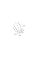
- a position (near point) S closest to the rearmost end 5a of the blade trailing edge 5 that can be a connection point P between the rear end of the blade backside line 2 and the back curve portion 4b is: It is set based on the radius R of the ventral side curved portion 4a having an arc shape. When the chord length is C, the radius R of this circle is often set to 0.5% to 2% of the chord length C.
- the most distant position (far point) from the rearmost end 5a of the blade trailing edge 5 that can be the connection point P between the rear end of the blade backside line 2 and the back curve portion 4b is to reduce the thickness of the blade trailing edge 5.
- the profile was set to 10% or less of the chord length from the rearmost end 5a of the blade trailing edge 5 in the profile.
- FIG. 2 shows a case where the connection point P between the rear end of the blade back side line 2 and the back curve portion 4 b is set to a position 5% of the chord length C from the rearmost end 5 a of the blade trailing edge 5.
- connection point between the ventral curve portion and the dorsal curve portion is about 30 ° around the center of the ventral curve portion located on the camber line and 30 ° on the dorsal ventral side of the camber line. It is set as the structure located in the range.
- connection point between the ventral curve portion and the dorsal curve portion can be shifted to both the dorsal side and the ventral side of the camber line, how to connect the ventral curve portion and the dorsal curve portion.
- the degree of freedom increases in manufacturing.
- the dorsal curve portion of the curve forming the blade trailing edge passes through a region closer to the camber line than the symmetrical curve portion that is in line symmetry with the ventral curve portion with the camber line in between. Since the rear end of the blade back line reaches the camber line, the main flow (air flow) at the back curve is accelerated and the boundary layer becomes smaller. In addition, the main flow becomes the dorsal curve by the Coanda effect. As a result, the outflow angle from the trailing edge of the main wing increases.
- the strength is ensured, and the loss due to the velocity distribution deficiency is suppressed and the performance is further improved without causing the fear that the blade weight may increase or the influence on the structural design.
- the outflow angle from the mainstream blade trailing edge can be increased, resulting in a very good effect of increasing work.
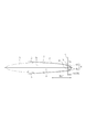
- FIG. 1 and 2 show the profile of a turbine blade according to an embodiment of the present invention.
- the turbine blade 1 has a profile including a blade back side line 2, a blade ventral side line 3, a blade trailing edge 5, and a blade leading edge 6.
- the rear ends of the blade back side line 2 and the blade ventral side line 3 are connected by a curve 4 in the profile.
- the curve 4 forming the blade trailing edge 5 in the profile is composed of a ventral curve portion 4a and a dorsal curve portion 4b.
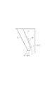
- the ventral curve portion 4a has an arc shape with a constant radius of curvature from the rear end of the wing ventral line 3 toward the camber line CL of the profile.
- the dorsal curve portion 4b is a symmetrical curve portion (a curve portion indicated by a two-dot chain line in the enlarged portion of FIG. 1) that is symmetrical with the ventral curve portion 4 with the camber line CL from the rear end of the blade dorsal line 2 in between. That is, it passes toward the camber line CL through a region closer to the camber line CL than the conventional back side curve portion).
- the ventral curve portion 4a and the dorsal curve portion 4b are connected to each other in the vicinity of the camber line CL.
- the dorsal curve portion 4 b is represented by an elliptical component line extending from the center of the curved portion along the major axis a direction of the ellipse A to the center of the curved portion along the minor axis b direction. Yes.
- connection point P between the rear end of the blade back line 2 and the back curve portion 4b of the curve 4 is to reduce the change in the natural frequency while reducing the thickness of the blade trailing edge 5. It is set at a position of 5% C (C is the chord length) from the rearmost end 5a of the blade trailing edge 5.
- the back curve portion 4b of the curve 4 forming the blade trailing edge 5 is connected to the camber line CL from the rear end of the blade back side line 2 than the symmetrical curve portion.
- the mainstream FP in the dorsal curve portion 4b is accelerated, and the Coanda effect causes the dorsal curve portion 4b to the ventral curve portion. 4a, and the outflow angle of the mainstream FP from the blade trailing edge 5 is increased as compared with the conventional mainstream FB that flows straight out from the conventional blade trailing edge 55 shown in FIG.
- the blade trailing edge (blade back side line and blade backside line in the conventional turbine blade indicated by a two-dot chain line in the enlarged portion of FIG.
- connection point between the ventral curve portion 4a and the dorsal curve portion 4b of the curve 4 forming the blade trailing edge 5 in the turbine blade 1 according to the present invention is the blade trailing edge 5 on the camber line CL.
- the present invention is not limited to this.
- the connection point Q between the ventral curve portion 4a and the dorsal curve portion 4b of the curve 4 is described. However, it is good also as a structure located in the site
- connection point Q between the ventral curve portion 4a and the dorsal curve portion 4b of the curve 4 may be positioned around the center O of the ventral curve portion 4a and in the range of 30 ° on the ventral side of the camber line CL. .
- connection point Q between the ventral curve portion 4a and the dorsal curve portion 4b can be shifted to the dorsal ventral side of the camber line CL, the connection between the ventral curve portion 4a and the dorsal curve portion 4b is possible. As a result, the degree of freedom in the method of spreading increases, and the manufacture becomes easier.
- the configuration of the turbine blade according to the present invention is not limited to the above-described embodiment.
Landscapes
- Engineering & Computer Science (AREA)
- Mechanical Engineering (AREA)
- General Engineering & Computer Science (AREA)
- Physics & Mathematics (AREA)
- Fluid Mechanics (AREA)
- Turbine Rotor Nozzle Sealing (AREA)
Abstract
Priority Applications (4)
| Application Number | Priority Date | Filing Date | Title |
|---|---|---|---|
| JP2013512478A JP5549825B2 (ja) | 2011-04-28 | 2012-04-27 | タービン翼 |
| CA2833859A CA2833859C (fr) | 2011-04-28 | 2012-04-27 | Pale de turbine a rebord arriere eliminant la perte |
| EP12776447.0A EP2703600B1 (fr) | 2011-04-28 | 2012-04-27 | Aube de turbine |
| US14/113,265 US9371734B2 (en) | 2011-04-28 | 2013-10-22 | Turbine blade |
Applications Claiming Priority (2)
| Application Number | Priority Date | Filing Date | Title |
|---|---|---|---|
| JP2011101266 | 2011-04-28 | ||
| JP2011-101266 | 2011-04-28 |
Related Child Applications (1)
| Application Number | Title | Priority Date | Filing Date |
|---|---|---|---|
| US14/113,265 Continuation US9371734B2 (en) | 2011-04-28 | 2013-10-22 | Turbine blade |
Publications (1)
| Publication Number | Publication Date |
|---|---|
| WO2012147938A1 true WO2012147938A1 (fr) | 2012-11-01 |
Family
ID=47072450
Family Applications (1)
| Application Number | Title | Priority Date | Filing Date |
|---|---|---|---|
| PCT/JP2012/061422 Ceased WO2012147938A1 (fr) | 2011-04-28 | 2012-04-27 | Aube de turbine |
Country Status (5)
| Country | Link |
|---|---|
| US (1) | US9371734B2 (fr) |
| EP (1) | EP2703600B1 (fr) |
| JP (1) | JP5549825B2 (fr) |
| CA (1) | CA2833859C (fr) |
| WO (1) | WO2012147938A1 (fr) |
Cited By (2)
| Publication number | Priority date | Publication date | Assignee | Title |
|---|---|---|---|---|
| WO2014069216A1 (fr) * | 2012-10-31 | 2014-05-08 | 株式会社Ihi | Aube de turbine |
| EP2927427A1 (fr) | 2014-04-04 | 2015-10-07 | MTU Aero Engines GmbH | Aube de turbine à gaz |
Families Citing this family (6)
| Publication number | Priority date | Publication date | Assignee | Title |
|---|---|---|---|---|
| EP3231996B1 (fr) * | 2016-04-11 | 2020-06-17 | Rolls-Royce plc | Aube pour une machine à flux axial |
| US20210215050A1 (en) * | 2018-09-12 | 2021-07-15 | General Electric Company | Hybrid elliptical-circular trailing edge for a turbine airfoil |
| GB2581351A (en) | 2019-02-13 | 2020-08-19 | Rolls Royce Plc | Blade for a gas turbine engine |
| EP4206440A4 (fr) * | 2020-12-03 | 2024-08-14 | IHI Corporation | Ventilateur à flux axial, procédé de modification de pale pour compresseur et turbine, et pale obtenue selon ledit modèle |
| US11840939B1 (en) * | 2022-06-08 | 2023-12-12 | General Electric Company | Gas turbine engine with an airfoil |
| CN116658345A (zh) * | 2023-07-17 | 2023-08-29 | 中国石油大学(华东) | 导轮/涡轮叶片、其设计方法及导轮与涡轮结构 |
Citations (4)
| Publication number | Priority date | Publication date | Assignee | Title |
|---|---|---|---|---|
| DE10039642A1 (de) * | 2000-08-14 | 2002-03-07 | Honda Motor Co Ltd | Turbinenblattluftflügel und Turbinenblatt für eine Axialstromturbine |
| JP2003254002A (ja) * | 2002-03-01 | 2003-09-10 | Honda Motor Co Ltd | 軸流型タービンのタービン翼型およびタービン翼 |
| JP2005076533A (ja) * | 2003-08-29 | 2005-03-24 | Toshiba Corp | タービン翼 |
| JP2011017290A (ja) | 2009-07-09 | 2011-01-27 | Mitsubishi Heavy Ind Ltd | 翼体および回転機械 |
Family Cites Families (4)
| Publication number | Priority date | Publication date | Assignee | Title |
|---|---|---|---|---|
| US6461110B1 (en) * | 2001-07-11 | 2002-10-08 | General Electric Company | First-stage high pressure turbine bucket airfoil |
| US6769879B1 (en) * | 2003-07-11 | 2004-08-03 | General Electric Company | Airfoil shape for a turbine bucket |
| DE102005025213B4 (de) * | 2005-06-01 | 2014-05-15 | Honda Motor Co., Ltd. | Schaufel einer Axialströmungsmaschine |
| EP2299124A1 (fr) * | 2009-09-04 | 2011-03-23 | Siemens Aktiengesellschaft | Aube de rotor pour un compresseur axial |
-
2012
- 2012-04-27 EP EP12776447.0A patent/EP2703600B1/fr active Active
- 2012-04-27 CA CA2833859A patent/CA2833859C/fr active Active
- 2012-04-27 WO PCT/JP2012/061422 patent/WO2012147938A1/fr not_active Ceased
- 2012-04-27 JP JP2013512478A patent/JP5549825B2/ja active Active
-
2013
- 2013-10-22 US US14/113,265 patent/US9371734B2/en active Active
Patent Citations (4)
| Publication number | Priority date | Publication date | Assignee | Title |
|---|---|---|---|---|
| DE10039642A1 (de) * | 2000-08-14 | 2002-03-07 | Honda Motor Co Ltd | Turbinenblattluftflügel und Turbinenblatt für eine Axialstromturbine |
| JP2003254002A (ja) * | 2002-03-01 | 2003-09-10 | Honda Motor Co Ltd | 軸流型タービンのタービン翼型およびタービン翼 |
| JP2005076533A (ja) * | 2003-08-29 | 2005-03-24 | Toshiba Corp | タービン翼 |
| JP2011017290A (ja) | 2009-07-09 | 2011-01-27 | Mitsubishi Heavy Ind Ltd | 翼体および回転機械 |
Non-Patent Citations (1)
| Title |
|---|
| See also references of EP2703600A4 |
Cited By (4)
| Publication number | Priority date | Publication date | Assignee | Title |
|---|---|---|---|---|
| WO2014069216A1 (fr) * | 2012-10-31 | 2014-05-08 | 株式会社Ihi | Aube de turbine |
| US10024167B2 (en) | 2012-10-31 | 2018-07-17 | Ihi Corporation | Turbine blade |
| EP2927427A1 (fr) | 2014-04-04 | 2015-10-07 | MTU Aero Engines GmbH | Aube de turbine à gaz |
| US9869184B2 (en) | 2014-04-04 | 2018-01-16 | MTU Aero Engines AG | Gas turbine blade |
Also Published As
| Publication number | Publication date |
|---|---|
| EP2703600B1 (fr) | 2024-01-17 |
| EP2703600A4 (fr) | 2014-10-15 |
| US9371734B2 (en) | 2016-06-21 |
| JP5549825B2 (ja) | 2014-07-16 |
| EP2703600A1 (fr) | 2014-03-05 |
| US20140112795A1 (en) | 2014-04-24 |
| JPWO2012147938A1 (ja) | 2014-07-28 |
| CA2833859C (fr) | 2016-12-13 |
| CA2833859A1 (fr) | 2012-11-01 |
Similar Documents
| Publication | Publication Date | Title |
|---|---|---|
| JP5549825B2 (ja) | タービン翼 | |
| JP5999348B2 (ja) | タービン翼 | |
| US9932960B2 (en) | Rotor blade of a wind turbine | |
| JP6524258B2 (ja) | タービンロータ翼の断面形状を決定するための方法 | |
| JP5558095B2 (ja) | タービン動翼翼列および蒸気タービン | |
| JP2012510018A (ja) | 翼の形状および対応する翼を最適化する方法 | |
| JP6525273B2 (ja) | プロペラ伴流の空気力学的な影響を打ち消す航空機および方法 | |
| WO2015134005A8 (fr) | Profil aérodynamique de turbine | |
| WO2015041801A3 (fr) | Diffuseur avec agitation vortex induite par traverses | |
| JP5351637B2 (ja) | 翼体および回転機械 | |
| JP2022510749A5 (fr) | ||
| JP2014528552A (ja) | 湾曲部を含むターボ機械センターブレード | |
| CN106536858A (zh) | 具有顺翼展延伸流阻断器的涡轮翼型件冷却系统 | |
| CN111907685A (zh) | 横截面厚度不同的凹凸面船舶舵 | |
| CN104763477B (zh) | 一种叶轮机械动叶叶尖部分围带结构 | |
| CN111699323B (zh) | 旋转叶片以及具备该旋转叶片的离心压缩机 | |
| JP6774044B2 (ja) | ファン及び圧縮機の静翼 | |
| KR20180022773A (ko) | 터보 기계류 회전자 블레이드 | |
| JP4944979B2 (ja) | 高転向・高遷音速翼 | |
| JP7210324B2 (ja) | 翼及びこれを備えた機械 | |
| JP5595532B2 (ja) | 翼体および回転機械 | |
| JP2019027751A5 (fr) | ||
| JP5456186B2 (ja) | 翼体および回転機械 | |
| WO2012090269A1 (fr) | Corps d'aube et machine rotative |
Legal Events
| Date | Code | Title | Description |
|---|---|---|---|
| 121 | Ep: the epo has been informed by wipo that ep was designated in this application |
Ref document number: 12776447 Country of ref document: EP Kind code of ref document: A1 |
|
| ENP | Entry into the national phase |
Ref document number: 2013512478 Country of ref document: JP Kind code of ref document: A |
|
| ENP | Entry into the national phase |
Ref document number: 2833859 Country of ref document: CA |
|
| WWE | Wipo information: entry into national phase |
Ref document number: 2012776447 Country of ref document: EP |
|
| NENP | Non-entry into the national phase |
Ref country code: DE |