WO2012148242A2 - 이동 단말기 및 그 제어 방법 - Google Patents
이동 단말기 및 그 제어 방법 Download PDFInfo
- Publication number
- WO2012148242A2 WO2012148242A2 PCT/KR2012/003362 KR2012003362W WO2012148242A2 WO 2012148242 A2 WO2012148242 A2 WO 2012148242A2 KR 2012003362 W KR2012003362 W KR 2012003362W WO 2012148242 A2 WO2012148242 A2 WO 2012148242A2
- Authority
- WO
- WIPO (PCT)
- Prior art keywords
- terminal
- mobile terminal
- neighboring
- location
- neighbor
- Prior art date
- Legal status (The legal status is an assumption and is not a legal conclusion. Google has not performed a legal analysis and makes no representation as to the accuracy of the status listed.)
- Ceased
Links
Images


Classifications
-
- H—ELECTRICITY
- H04—ELECTRIC COMMUNICATION TECHNIQUE
- H04W—WIRELESS COMMUNICATION NETWORKS
- H04W4/00—Services specially adapted for wireless communication networks; Facilities therefor
- H04W4/02—Services making use of location information
- H04W4/025—Services making use of location information using location based information parameters
-
- H—ELECTRICITY
- H04—ELECTRIC COMMUNICATION TECHNIQUE
- H04W—WIRELESS COMMUNICATION NETWORKS
- H04W4/00—Services specially adapted for wireless communication networks; Facilities therefor
- H04W4/02—Services making use of location information
- H04W4/029—Location-based management or tracking services
-
- H—ELECTRICITY
- H04—ELECTRIC COMMUNICATION TECHNIQUE
- H04W—WIRELESS COMMUNICATION NETWORKS
- H04W4/00—Services specially adapted for wireless communication networks; Facilities therefor
- H04W4/02—Services making use of location information
-
- H—ELECTRICITY
- H04—ELECTRIC COMMUNICATION TECHNIQUE
- H04W—WIRELESS COMMUNICATION NETWORKS
- H04W4/00—Services specially adapted for wireless communication networks; Facilities therefor
- H04W4/02—Services making use of location information
- H04W4/023—Services making use of location information using mutual or relative location information between multiple location based services [LBS] targets or of distance thresholds
-
- H—ELECTRICITY
- H04—ELECTRIC COMMUNICATION TECHNIQUE
- H04W—WIRELESS COMMUNICATION NETWORKS
- H04W4/00—Services specially adapted for wireless communication networks; Facilities therefor
- H04W4/30—Services specially adapted for particular environments, situations or purposes
- H04W4/33—Services specially adapted for particular environments, situations or purposes for indoor environments, e.g. buildings
-
- H—ELECTRICITY
- H04—ELECTRIC COMMUNICATION TECHNIQUE
- H04W—WIRELESS COMMUNICATION NETWORKS
- H04W64/00—Locating users or terminals or network equipment for network management purposes, e.g. mobility management
-
- H—ELECTRICITY
- H04—ELECTRIC COMMUNICATION TECHNIQUE
- H04W—WIRELESS COMMUNICATION NETWORKS
- H04W88/00—Devices specially adapted for wireless communication networks, e.g. terminals, base stations or access point devices
- H04W88/02—Terminal devices
Definitions
- the present invention relates to a mobile terminal and a method of controlling the same so that the use of the terminal can be implemented in consideration of user convenience.
- Terminal can move It may be divided into a mobile terminal (portable terminal) and a stationary terminal according to whether or not.
- the mobile terminal may be further classified into a handheld terminal and a vehicle mount terminal according to whether a user can directly carry it.
- such a terminal is a multimedia player having a complex function such as taking a picture or a video, playing a music or video file, playing a game, or receiving a broadcast. Is being implemented.
- the mobile terminal may be applied as a component of a home automation system for remotely controlling home appliances located in a home.
- the home automation service is for remotely controlling the operation of home appliances located in a house, and a mobile terminal may be used as the control means.
- the user can control home appliances in the house at any time as long as the user carries the mobile terminal.
- the present invention has been proposed to meet the above-mentioned needs, and an object of the present invention is to provide a mobile terminal and a method of controlling the same, which can enhance user convenience using the mobile terminal.
- an object of the present invention is to provide an appropriate service to a mobile terminal based on a location where the mobile terminal is located.
- an object of the present invention is to provide information about a neighboring terminal adjacent to the mobile terminal, based on the location where the mobile terminal is located.
- the present invention is to allow the communication between the mobile terminal and the neighboring terminal to perform a predetermined data from the neighboring terminal expected to be exposed to the same environment as the mobile terminal, or to control the operation of the neighboring terminal. There is a purpose.
- the present invention is to detect the location of the mobile terminal, and the image of the location corresponding to the location of the mobile terminal and neighbor terminal information about at least one neighboring terminal placed in the same place as the mobile terminal from the outside;
- a wireless communication unit for receiving;
- a controller configured to generate a device map for displaying the neighboring terminal located at the same place as the mobile terminal based on the place image and the neighboring terminal information;
- a memory for storing the device map;
- a display unit for displaying the device map.
- the neighbor terminal information may correspond to the neighbor terminal located within a predetermined distance from the mobile terminal or correspond to the neighbor terminal belonging to the same network cell as the wireless communication unit.
- the memory further stores a search parameter designating a terminal category, and the controller determines whether the neighboring device is classified into a terminal category defined by the search parameter, and the neighboring terminal is classified into a terminal category defined by the search parameter.
- the neighboring device may be displayed on the device map.
- the controller may generate the device map by displaying the location of the adjacent terminal on the place image.
- the present invention has an effect that can provide information about the neighboring terminal adjacent to the mobile terminal, based on the location where the mobile terminal is located.
- the present invention by the communication between the mobile terminal and the neighboring terminal, by receiving a predetermined data from the neighboring terminal expected to be exposed to the same environment as the mobile terminal, or the effect of remotely controlling the operation of the neighboring terminal There is.
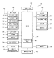
- FIG. 1 is a block diagram of a mobile terminal according to an embodiment of the present invention.
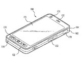
- Figure 2a is a front perspective view of a mobile terminal according to an embodiment of the present invention.
- FIG. 2b is a rear perspective view of a mobile terminal according to one embodiment of the present invention.
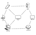
- FIG. 3 is a schematic diagram of a system for constructing a location-based device map using a mobile terminal 100 according to the present invention.
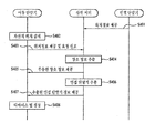
- FIG. 4 is an operation flowchart of a system for constructing a location-based device map using a mobile terminal according to the present invention
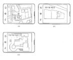
- 5A to 5C are exemplary diagrams illustrating a place image provided to a mobile terminal.
- FIG. 6 is an exemplary diagram for describing a neighboring terminal belonging to the same network cell as the mobile terminal
- FIG. 7 is an operation flowchart of a mobile terminal according to an embodiment of the present invention.
- FIG. 8 is an exemplary view of a screen provided to a user for designating a terminal category as a search parameter.
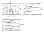
- 9A-9C illustrate an example device map displayed via a mobile terminal.
- 10 is an exemplary diagram of an Ad-hoc network formed between a mobile terminal and an adjacent terminal.
- 11A to 11C are exemplary diagrams for explaining a mobile terminal reading a shared file shared by a neighboring terminal.
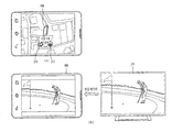
- 12A and 12B are exemplary diagrams for explaining that a mobile terminal outputs the same screen as a neighboring terminal.
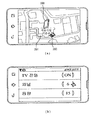
- 13A and 13B are exemplary diagrams for controlling the operation of a neighboring terminal through a mobile terminal.
- 14A to 14C are exemplary diagrams for explaining that a first event occurs in a neighboring terminal and a second event occurs in a mobile terminal.
- 15A and 15B are exemplary diagrams for describing transmitting a text message or an instant message to a neighbor terminal through a mobile terminal.
- 16A and 16B are exemplary views for explaining the case where the above-described embodiments 1 to 6 are used in a combined form in one mobile terminal.
- 17 is an exemplary diagram of a device map when the mobile terminal is present inside a vehicle traveling on a road;
- the mobile terminal described herein may include a mobile phone, a smart phone, a laptop computer, a digital broadcasting terminal, a personal digital assistant (PDA), a portable multimedia player (PMP), navigation, and the like.
- PDA personal digital assistant
- PMP portable multimedia player
- the configuration according to the embodiments described herein may also be applied to fixed terminals such as digital TVs, desktop computers, etc., except when applicable only to mobile terminals.
- FIG. 1 is a block diagram of a mobile terminal according to an embodiment of the present invention.
- the mobile terminal 100 includes a wireless communication unit 110, an A / V input unit 120, a user input unit 130, a sensing unit 140, an output unit 150, a memory 160, and an interface.
- the unit 170, the controller 180, and the power supply unit 190 may be included.
- the components shown in FIG. 1 are not essential, so that a mobile terminal having more or fewer components may be implemented.
- the wireless communication unit 110 may include one or more modules that enable wireless communication between the mobile terminal 100 and the wireless communication system or between the mobile terminal 100 and a network in which the mobile terminal 100 is located.
- the wireless communication unit 110 may include a broadcast receiving module 111, a mobile communication module 112, a wireless internet module 113, a short range communication module 114, a location information module 115, and the like. .
- the broadcast receiving module 111 receives a broadcast signal and / or broadcast related information from an external broadcast management server through a broadcast channel.
- the broadcast channel may include a satellite channel and a terrestrial channel.
- Two or more broadcast reception modules 1100 may be provided to the mobile terminal 100 for simultaneous broadcast reception or broadcast channel switching for at least two broadcast channels.
- the broadcast management server may mean a server that generates and transmits a broadcast signal and / or broadcast related information or a server that receives a previously generated broadcast signal and / or broadcast related information and transmits the same to a terminal.
- the broadcast signal may include not only a TV broadcast signal, a radio broadcast signal, and a data broadcast signal, but also a broadcast signal having a data broadcast signal combined with a TV broadcast signal or a radio broadcast signal.
- the broadcast associated information refers to information related to a broadcast channel, a broadcast program, or a broadcast service provider.
- the broadcast related information may also be provided through a mobile communication network. In this case, it may be received by the mobile communication module 112.
- the broadcast related information may exist in various forms. For example, it may exist in the form of Electronic Program Guide (EPG) of Digital Multimedia Broadcasting (DMB) or Electronic Service Guide (ESG) of Digital Video Broadcast-Handheld (DVB-H).
- EPG Electronic Program Guide
- DMB Digital Multimedia Broadcasting
- ESG Electronic Service Guide
- DVB-H Digital Video Broadcast-Handheld
- the broadcast receiving module 111 may include, for example, Digital Multimedia Broadcasting-Terrestrial (DMB-T), Digital Multimedia Broadcasting-Satellite (DMB-S), Media Forward Link Only (MediaFLO), and Digital Video Broadcast (DVB-H). -Handheld), DVB-CBMS (Convergence of Broadcasting and Mobile Service), OMA-BCAST (Open Mobile Alliance-BroadCAST), CMMB (China Multimedia Mobile Broadcasting), MBBMS (Mobile Broadcasting Business Management System), ISDB-T (Integrated Services) Digital broadcast signals may be received using a digital broadcast system such as Digital Broadcast-Terrestrial.
- the broadcast receiving module 111 may be configured to be suitable for not only the above-described digital broadcasting system but also other broadcasting systems.
- the broadcast signal and / or broadcast related information received through the broadcast receiving module 111 may be stored in the memory 160.
- the mobile communication module 112 may include at least one of a base station, an external terminal, and a server on a mobile communication network such as but not limited to Gobal System for Mobile communications (GSM), Code Division Multiple Access (CDMA), and Wideband CDMA (WCDMA). Send and receive wireless signals with one.
- the wireless signal may include various types of data according to transmission and reception of a voice call signal, a video call call signal, or a text / multimedia message.
- the wireless internet module 113 refers to a module for wireless internet access and may be embedded or external to the mobile terminal 100.
- Wireless Internet technologies include Wireless LAN (Wi-Fi), Wireless Broadband (Wibro), World Interoperability for Microwave Access (Wimax), High Speed Downlink Packet Access (HSDPA), GSM, CDMA, WCDMA, Long Term Evolution), but is not limited to such.
- the wireless Internet module 113 for performing a wireless Internet access through the mobile communication network is the mobile communication module.
- (112) may be understood as a kind.
- the short range communication module 114 refers to a module for short range communication.
- Bluetooth Radio Frequency Identification (RFID), Infrared Data Association (IrDA), Ultra Wideband (UWB), ZigBee, Near Field Communication (NFC), etc. may be used. have.
- RFID Radio Frequency Identification
- IrDA Infrared Data Association
- UWB Ultra Wideband
- ZigBee ZigBee
- NFC Near Field Communication
- the location information module 115 is a module for obtaining a location of a mobile terminal, and a representative example thereof is a GPS (Global Position System) module.
- the GPS module 115 calculates distance information and accurate time information away from three or more satellites, and then applies trigonometric methods to the calculated information, thereby providing three-dimensional chords according to latitude, longitude, and altitude.
- the location information can be calculated accurately.
- a method of calculating position and time information using three satellites and correcting the error of the calculated position and time information using another satellite is widely used.
- the GPS module 115 may calculate speed information by continuously calculating the current position in real time.
- the A / V input unit 120 is for inputting an audio signal or a video signal, and may include a camera 121 and a microphone 122.
- the camera 121 processes image frames such as still images or moving images obtained by the image sensor in the video call mode or the photographing mode.
- the processed image frame may be displayed on the display unit 151.
- the image frame processed by the camera 121 may be stored in the memory 160 or transmitted to the outside through the wireless communication unit 110. Two or more cameras 121 may be provided according to the use environment.
- the microphone 122 receives an external sound signal by a microphone in a call mode, a recording mode, a voice recognition mode, etc., and processes the external sound signal into electrical voice data.
- the processed voice data may be converted into a form transmittable to the mobile communication base station through the mobile communication module 112 and output in the call mode.
- the microphone 122 may implement various noise removing algorithms for removing noise generated in the process of receiving an external sound signal.
- the user input unit 130 generates input data for the user to control the operation of the terminal.
- the user input unit 130 may include a key pad, a dome switch, a touch pad (constant voltage / capacitance), a jog wheel, a jog switch, and the like.
- the sensing unit 140 detects a current state of the mobile terminal 100 such as an open / closed state of the mobile terminal 100, a location of the mobile terminal 100, presence or absence of a user contact, orientation of the mobile terminal, acceleration / deceleration of the mobile terminal, and the like. To generate a sensing signal for controlling the operation of the mobile terminal 100. For example, when the mobile terminal 100 is in the form of a slide phone, it may sense whether the slide phone is opened or closed. In addition, whether the power supply unit 190 is supplied with power, whether the interface unit 170 is coupled to the external device may be sensed. On the other hand, the sensing unit 140 may include a proximity sensor 141, although not shown may further include an acceleration sensor, gravity sensor, gyro sensor and the like.
- the output unit 150 is used to generate an output related to sight, hearing, or tactile sense, and includes a display unit 151, an audio output module 152, an alarm unit 153, and a haptic module 154. Can be.
- the display unit 151 displays (outputs) information processed by the mobile terminal 100. For example, when the mobile terminal is in a call mode, the mobile terminal displays a user interface (UI) or a graphic user interface (GUI) related to the call. When the mobile terminal 100 is in a video call mode or a photographing mode, the mobile terminal 100 displays a photographed and / or received image, UI, or GUI.
- UI user interface
- GUI graphic user interface
- the display unit 151 includes a liquid crystal display (LCD), a thin film transistor-liquid crystal display (TFT LCD), an organic light-emitting diode (OLED), and a flexible display (flexible). and at least one of a 3D display.
- LCD liquid crystal display
- TFT LCD thin film transistor-liquid crystal display
- OLED organic light-emitting diode
- flexible display flexible display
- Some of these displays can be configured to be transparent or light transmissive so that they can be seen from the outside. This may be referred to as a transparent display.
- a representative example of the transparent display is TOLED (Transparant OLED).
- the rear structure of the display unit 151 may also be configured as a light transmissive structure. With this structure, the user can see the object located behind the terminal body through the area occupied by the display unit 151 of the terminal body.
- a plurality of display units may be spaced apart or integrally disposed on one surface of the mobile terminal 100, or may be disposed on different surfaces, respectively.
- the display unit 151 and a sensor for detecting a touch operation form a mutual layer structure (hereinafter, referred to as a touch screen)
- the display unit 151 may be configured in addition to an output device. Can also be used as an input device.
- the touch sensor may have, for example, a form of a touch film, a touch sheet, a touch pad, or the like.
- the touch sensor may be configured to convert a change in pressure applied to a specific portion of the display unit 151 or capacitance generated in a specific portion of the display unit 151 into an electrical input signal.
- the touch sensor may be configured to detect not only the position and area of the touch but also the pressure at the touch.
- the corresponding signal (s) is sent to a touch controller (not shown).
- the touch controller processes the signal (s) and then transmits the corresponding data to the controller 180.
- the controller 180 can know which area of the display unit 151 is touched.
- the proximity sensor 141 may be disposed in an inner region of the mobile terminal surrounded by the touch screen or near the touch screen.
- the proximity sensor refers to a sensor that detects the presence or absence of an object approaching a predetermined detection surface or an object present in the vicinity without using a mechanical contact by using an electromagnetic force or infrared rays.
- Proximity sensors have a longer life and higher utilization than touch sensors.
- the proximity sensor examples include a transmission photoelectric sensor, a direct reflection photoelectric sensor, a mirror reflection photoelectric sensor, a high frequency oscillation proximity sensor, a capacitive proximity sensor, a magnetic proximity sensor, and an infrared proximity sensor.
- the touch screen is capacitive, the touch screen is configured to detect the proximity of the pointer by the change of the electric field according to the proximity of the pointer.
- the touch screen may be classified as a proximity sensor.
- proximity touch an act of allowing the pointer to be recognized without being in contact with the touch screen so that the pointer is located on the touch screen.
- contact touch an act of actually touching the pointer on the touch screen.
- the position where the proximity touch is performed by the pointer on the touch screen may mean a position where the pointer is perpendicular to the touch screen when the pointer is in proximity touch.
- the proximity sensor detects a proximity touch and a proximity touch pattern (for example, a proximity touch distance, a proximity touch direction, a proximity touch speed, a proximity touch time, a proximity touch position, and a proximity touch movement state).
- a proximity touch and a proximity touch pattern for example, a proximity touch distance, a proximity touch direction, a proximity touch speed, a proximity touch time, a proximity touch position, and a proximity touch movement state.
- Information corresponding to the sensed proximity touch operation and proximity touch pattern may be output on the touch screen.
- the sound output module 152 may output audio data received from the wireless communication unit 110 or stored in the memory 160 in a call signal reception, a call mode or a recording mode, a voice recognition mode, a broadcast reception mode, and the like.
- the sound output module 152 may also output a sound signal related to a function (eg, a call signal reception sound, a message reception sound, etc.) performed in the mobile terminal 100.
- the sound output module 152 may include a receiver, a speaker, a buzzer, and the like.
- the alarm unit 153 outputs a signal for notifying occurrence of an event of the mobile terminal 100. Examples of events occurring in the mobile terminal include call signal reception, message reception, key signal input, and touch input.
- the alarm unit 153 may output a signal for notifying occurrence of an event in a form other than a video signal or an audio signal, for example, vibration. Since the video signal or the audio signal may be output through the display unit 151 or the audio output module 152, in this case, the display unit 151 and the audio output module 152 are a kind of alarm unit 153. It may be classified as.
- the haptic module 154 generates various haptic effects that a user can feel. Vibration is a representative example of the haptic effect generated by the haptic module 154.
- the intensity and pattern of vibration generated by the haptic module 154 can be controlled. For example, different vibrations may be synthesized and output or may be sequentially output.
- the haptic module 154 may be configured to provide a pin array that vertically moves with respect to the contact skin surface, a jetting force or suction force of air through the jetting or suction port, grazing to the skin surface, contact of the electrode, electrostatic force, and the like.
- Various tactile effects can be generated, such as effects by the endothermic and the reproduction of a sense of cold using the elements capable of endotherm or heat generation.
- the haptic module 154 may not only deliver the haptic effect through direct contact, but also may implement the user to feel the haptic effect through a muscle sense such as a finger or an arm. Two or more haptic modules 154 may be provided according to configuration aspects of the mobile terminal 100.
- the memory unit 160 may store a program for processing and controlling the controller 180, and temporarily stores input / output data (for example, a phone book, a message, an audio, a still image, a video, etc.). It can also perform a function for.
- the memory unit 160 may store a frequency of use of each of the data (eg, a phone number, a message, and a frequency of use of each multimedia).
- the memory unit 160 may store data regarding vibration and sound of various patterns output when a touch input on the touch screen is performed.
- the memory 160 may be a flash memory type, a hard disk type, a multimedia card micro type, a card type memory (for example, SD or XD memory), RAM (Random Access Memory, RAM), Static Random Access Memory (SRAM), Read-Only Memory (ROM), Electrically Erasable Programmable Read-Only Memory (EEPROM), Programmable Read-Only Memory (PROM), Magnetic Memory, Magnetic It may include a storage medium of at least one type of disk, optical disk.
- the mobile terminal 100 may operate in connection with a web storage that performs a storage function of the memory 160 on the Internet.
- the interface unit 170 serves as a path with all external devices connected to the mobile terminal 100.
- the interface unit 170 receives data from an external device, receives power, transfers the power to each component inside the mobile terminal 100, or transmits data inside the mobile terminal 100 to an external device.
- wired / wireless headset ports, external charger ports, wired / wireless data ports, memory card ports, ports for connecting devices with identification modules, audio input / output (I / O) ports, The video input / output (I / O) port, the earphone port, and the like may be included in the interface unit 170.
- the identification module is a chip that stores various types of information for authenticating the usage rights of the mobile terminal 100, and includes a user identification module (UIM), a subscriber identify module (SIM), and a universal user authentication module ( Universal Subscriber Identity Module (USIM), and the like.
- a device equipped with an identification module (hereinafter referred to as an 'identification device') may be manufactured in the form of a smart card. Therefore, the identification device may be connected to the terminal 100 through a port.
- the interface unit may be a passage through which power from the cradle is supplied to the mobile terminal 100 when the mobile terminal 100 is connected to an external cradle, or various command signals input from the cradle by a user may be transferred. It may be a passage that is delivered to the terminal. Various command signals or power input from the cradle may be operated as signals for recognizing that the mobile terminal is correctly mounted on the cradle.
- the controller 180 typically controls the overall operation of the mobile terminal. For example, perform related control and processing for voice calls, data communications, video calls, and the like.
- the controller 180 may include a multimedia module 181 for playing multimedia.
- the multimedia module 181 may be implemented in the controller 180 or may be implemented separately from the controller 180.
- the controller 180 may perform a pattern recognition process for recognizing a writing input or a drawing input performed on the touch screen as text and an image, respectively.
- the power supply unit 190 receives an external power source and an internal power source under the control of the controller 180 to supply power for operation of each component.
- Various embodiments described herein may be implemented in a recording medium readable by a computer or similar device using, for example, software, hardware or a combination thereof.
- the embodiments described herein include application specific integrated circuits (ASICs), digital signal processors (DSPs), digital signal processing devices (DSPDs), programmable logic devices (PLDs), field programmable gate arrays (FPGAs), and the like. It may be implemented using at least one of processors, controllers, micro-controllers, microprocessors, and electrical units for performing other functions. The described embodiments may be implemented by the controller 180 itself.
- ASICs application specific integrated circuits
- DSPs digital signal processors
- DSPDs digital signal processing devices
- PLDs programmable logic devices
- FPGAs field programmable gate arrays
- embodiments such as the procedures and functions described herein may be implemented as separate software modules.
- Each of the software modules may perform one or more functions and operations described herein.
- Software code may be implemented in software applications written in a suitable programming language. The software code may be stored in the memory 160 and executed by the controller 180.
- FIG. 2A is a front perspective view of an example of a mobile terminal or a portable terminal according to the present invention.
- the disclosed mobile terminal 100 has a terminal body in the form of a bar.
- the present invention is not limited thereto and may be applied to various structures such as a slide type, a folder type, a swing type, a swivel type, and two or more bodies are coupled to be relatively movable.
- the body includes a casing (casing, housing, cover, etc.) that forms an exterior.
- the case may be divided into a front case 101 and a rear case 102.
- Various electronic components are built in the space formed between the front case 101 and the rear case 102.
- At least one intermediate case may be further disposed between the front case 101 and the rear case 102.
- the cases may be formed by injecting synthetic resin or may be formed of a metal material, for example, a metal material such as stainless steel (STS) or titanium (Ti).
- a metal material such as stainless steel (STS) or titanium (Ti).
- the display unit 151, the audio output unit 152, the camera 121, the user input units 130/131 and 132, the microphone 122, and the interface 170 may be disposed in the terminal body, mainly the front case 101. have.
- the display unit 151 occupies most of the main surface of the front case 101.
- the audio output unit 151 and the camera 121 are disposed in regions adjacent to one end of both ends of the display unit 151, and the user input unit 131 and the microphone 122 are disposed in regions adjacent to the other end.
- the user input unit 132 and the interface 170 may be disposed on side surfaces of the front case 101 and the rear case 102.
- the user input unit 130 is manipulated to receive a command for controlling the operation of the mobile terminal 100, and may include a plurality of manipulation units 131 and 132.
- the manipulation units 131 and 132 may also be collectively referred to as a manipulating portion.
- Content input by the first or second manipulation units 131 and 132 may be variously set.
- the first manipulation unit 131 receives a command such as start, end, scroll, and the like, and the second manipulation unit 132 adjusts the volume of the sound output from the sound output unit 152 or displays 151.
- Command such as activating / deactivating the touch recognition mode.
- FIG. 2B is a rear perspective view of the mobile terminal shown in FIG. 2A.
- a camera 121 ′ may be additionally mounted on the rear of the terminal body, that is, the rear case 102.
- the camera 121 ′ has a photographing direction substantially opposite to that of the camera 121 (see FIG. 2A), and may be a camera having the same or different pixels as the camera 121.
- the camera 121 has a low pixel so that the user's face is photographed and transmitted to the counterpart in case of a video call, and the camera 121 'photographs a general subject and does not immediately transmit it. It is desirable to have a high pixel because there are many.
- the cameras 121 and 121 ' may be installed on the terminal body to be rotatable or pop-up.
- the flash 123 and the mirror 124 may be further disposed adjacent to the camera 121 ′.
- the flash 123 shines light toward the subject when the subject is photographed by the camera 121 '.
- the mirror 124 allows the user to see his / her own face or the like when photographing (self-photographing) the user using the camera 121 '.
- the sound output unit 152 ' may be further disposed on the rear surface of the terminal body.
- the sound output unit 152 ′ may implement a stereo function together with the sound output unit 152 (see FIG. 2A), and may be used to implement a speakerphone mode during a call.
- an antenna 116 for receiving a broadcast signal may be additionally disposed on the side of the terminal body.
- the antenna 116 constituting a part of the broadcast receiving module 111 (refer to FIG. 1) may be installed to be pulled out of the terminal body.
- the terminal body is equipped with a power supply unit 190 for supplying power to the mobile terminal 100.
- the power supply unit 190 may be embedded in the terminal body or may be directly detachable from the outside of the terminal body.
- the rear case 102 may be further equipped with a touch pad 135 for sensing a touch.
- the touch pad 135 may be configured to be light transmissive for the display unit 151.
- the display unit 151 is configured to output visual information on both sides (i.e., in the direction of both the front and rear surfaces of the mobile terminal), the visual information may be recognized through the touch pad 135. do.
- the information output on both surfaces may be controlled by the touch pad 135.
- the touch screen may be disposed on the rear case 102.
- the touch pad 135 operates in association with the display unit 151 of the front case 101.
- the touch pad 135 may be disposed in parallel to the rear of the display unit 151.
- the touch pad 135 may have the same or smaller size as the display unit 151.
- the device map construction system includes a mobile terminal 100, a neighboring terminal 200, and a higher layer that collects and stores location information from the mobile terminal 100 and the neighboring terminal 200.
- Server 300 may be included.
- the adjacent terminal 200 is an apparatus for receiving data from the mobile terminal 100 or transmitting data to the mobile terminal 100 in cooperation with the mobile terminal 100.
- the neighboring terminal 200 may communicate with the higher server 300 periodically (or aperiodically) to provide its location to the higher server 300.
- the upper server 300 collects location information from the mobile terminal 100 and the neighboring terminal 200 and, based on the collected location information, relates to the neighboring terminal 200 located in the same place as the mobile terminal 100. Information may be provided to the mobile terminal 100.
- the higher server 300 may determine that the adjacent terminal 200 connected to the same wireless station 400 as the mobile terminal 100 is located at the same place as the mobile terminal 100.
- the upper server 300 may control a place image corresponding to a place where the mobile terminal 100 is located to be provided to the mobile terminal 100.
- the mobile terminal 100 receives information about a neighboring terminal 200 and a place image from the upper server 300, and generates a device map based on the received information.
- the device map is for displaying the neighboring terminal 200 located in the same place as the mobile terminal 100. By selecting any one of the neighboring terminals 200 displayed on the device map, the device map is selected to be adjacent to the mobile terminal 100.
- the terminal 200 may be linked. However, the mobile terminal 100 does not necessarily need to receive information about the neighboring terminal from the upper server 300. The mobile terminal 100 may also receive neighbor terminal information directly from the neighbor terminal 200.
- the upper server 300 may collect location information of the neighboring terminal 200 periodically (or aperiodically) (S401).
- the adjacent terminal 200 may provide its location information periodically (or aperiodically) to the upper server 300.
- the adjacent terminal 200 may obtain location information through a triangulation method using GPS, WPS or a base station.
- the collected information may be stored as a location database in the upper server 300.
- both the neighboring terminal 200 and the mobile terminal 100 allow their location information to be provided to the upper server 300.
- the upper server 300 may collect neighboring terminal information from the neighboring terminal 200 that allows authentication for device map formation. Thereafter, the device map creation request signal to the mobile terminal 100 through an external input.
- the mobile terminal 100 may detect its location through the location information module 115 (S402). When the location of the mobile terminal 100 is detected, the mobile terminal 100 transmits the detected location to the higher server 300 and, together with the request signal requesting a place image and neighboring terminal information for generating a device map. There is (S403).
- the upper server 300 may extract a place image corresponding to the position of the mobile terminal 100 received from the mobile terminal 100 from the place image base (S404) and provide the same to the mobile terminal 100 (S405).
- the place image is a map image corresponding to the location of the mobile terminal 100, a photographing (or picture) image of the surrounding environment of the mobile terminal 100, or a blueprint or photograph of a place or building where the mobile terminal 100 is located. (Or picture) images.
- the mobile terminal 100 is located in an art gallery, at least one of the images illustrated in FIGS. 5A to 5C may be provided to the mobile terminal 100.
- 5A through 5C illustrate place images provided to the mobile terminal 100.
- the upper server 300 may provide the mobile terminal 100 with a map image indicating a location of the museum as a place image.
- a map image indicating a location of the museum as a place image.
- an image taken inside the museum may be provided as a place image.
- a blueprint of a museum may be provided as a place image.
- the upper server 300 may extract the adjacent terminal 200 located at the same place as the mobile terminal 100 from the location information database (S406).
- the upper server 300 may provide neighboring terminal information on the neighboring terminal 200 to the mobile terminal 100 (S407).
- the neighbor terminal information may include location information of the neighbor terminal (which may be 3D location information), type information of the neighbor terminal, service information provided by the neighbor terminal 200, network support information of the neighbor terminal 200, and security related information. It may include at least one of authentication information, a separation distance between the neighboring terminal 200 and the mobile terminal 100, and an address (IP / MAC address) of the neighboring terminal.
- the mobile terminal 100 may generate a device map in which the neighboring terminal 200 is displayed on the place image received from the upper server 300 (S408).
- the mobile terminal 100 may control the device map to be generated by displaying the location of the adjacent terminal 200 on the place image.
- a user may be provided with a list of adjacent terminals 200 adjacent to the mobile terminal 100.
- the mobile terminal 100 interlocks with the neighbor terminal 200 to receive data from the neighbor terminal 200 or provide data stored in the mobile terminal 100 to the neighbor terminal 200 to provide the neighbor terminal 200. ) Can further increase the utilization.
- the exact location of the adjacent terminal 200 need not be displayed on the device map. It is sufficient that the neighboring terminal 200 is simply displayed on the image provided by the neighboring terminal 200 as the place image, and the exact position of the neighboring terminal 200 is not necessarily displayed. Furthermore, when creating a device map, the place image does not necessarily need to be included.
- the receiving process of the place image may be omitted in some cases. When the process of receiving a place image is omitted, the mobile terminal 100 may generate a device map by using an image previously stored in the memory 160 or generate a device map on a background of a black and white screen.
- FIG. 4 illustrates that the mobile terminal 100 obtains a place image from the upper server 300, the place image does not necessarily need to be obtained from the upper server 300.
- the mobile terminal 100 may obtain a place image from the neighboring terminal 200 or receive a place image from a wireless station (for example, an AP, a base station, a femto cell, etc.) connected to the mobile terminal 100. If the adjacent terminal 200 is located in the same building as the mobile terminal 100 or the adjacent terminal 200 is located in the same administrative area as the mobile terminal 100, the adjacent terminal 200 is the mobile terminal. When the location is located on the same road as 100 or when the adjacent terminal 200 is located within a predetermined radius of the mobile terminal 100, the adjacent terminal 200 may be determined to be located at the same place as the mobile terminal 100. have.
- a wireless station for example, an AP, a base station, a femto cell, etc.
- the upper server 300 may determine that the adjacent terminal 200 belonging to the same network cell (or coverage) as the mobile terminal 100 is located at the same place as the mobile terminal. Specifically, when the neighboring terminal 200 is connected to the same AP, the same base station, or the same femtocell as the mobile terminal 100, the upper server 300 is the same network cell (the mobile terminal 100 and the neighboring terminal 200) Or coverage). That is, the upper server 300 may determine whether the mobile terminal 100 and the neighboring terminal 200 belong to the same network cell (or coverage) in units of wireless stations such as an AP, a base station, or a femtocell.
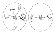
- FIG. 6 is an exemplary diagram for describing a neighboring terminal 200 belonging to the same network cell as the mobile terminal 100.
- the mobile terminal 100 is connected to AP # 1.
- a TV, a laptop, a tablet PC, a desktop, and the like, which are connected to the same AP as the mobile terminal 100 (ie, AP # 1) belong to the same network cell as the mobile terminal 100 described in the present embodiment. It can be described as (200). That is, if the mobile terminal 100 and the adjacent terminal 200 are connected to different APs, the mobile terminal 100 and the adjacent terminal 200 may not be regarded as being located at the same place.
- the TV and the laptop connected to the same AP (AP # 1) as the wireless communication unit 110 may determine that they belong to the same network cell as the wireless communication unit 110, while the wireless communication unit A washing machine, a robot cleaner, or the like connected to an AP (AP # 2) different from 110 may not be viewed as an adjacent terminal 200 belonging to the same network cell as the wireless communication unit 110.
- the adjacent terminal 200 determined to be the same place as the mobile terminal 100 may be a washing machine, a robot cleaner, or the like. It may change.
- the upper server 300 the controller 180 compares the address information of the neighboring terminal 200 received from the neighboring terminal 200 with the address information of the mobile terminal 100, and thereby the mobile terminal 100 and the neighboring terminal 200. ) May be determined to belong to the same network cell.
- step S406 and S407 the process of providing the neighboring terminal information is performed after the process of providing the place image (steps S404 and S405) is performed, but each of them must be performed in the order shown. The process does not have to go on.
- the process of providing the neighboring terminal information the process of providing the place image may be performed as well as the process of providing the place image and the process of providing the neighboring terminal information.
- the mobile terminal 100 illustrated in FIGS. 3 and 4 will be described in detail.
- the mobile terminal 100 described in the present invention includes at least some of the components configured in FIG. 1.
- the mobile terminal 100 described in the present invention may include a wireless communication unit 110, a user input unit (display unit 151, memory 160, and controller 180) among the components shown in FIG. 1. have.
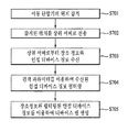
- FIG. 7 is an operation flowchart of a mobile terminal 100 according to an embodiment of the present invention.
- the controller 180 activates and moves the location information module 115 included in the wireless communication unit 110.
- the location of the terminal 100 may be controlled to be sensed (S701).
- the location information module 115 acquires the location of the mobile terminal 100 using a GPS (Global Positioning System), or uses the Wi-Fi Positioning System (WPS) and / or a base station (BS) triangulation method. May be obtained.
- the mobile terminal 100 may be provided with location information through a server (eg, LBSP) provided by an ISP (Internet Service Provider) or a device corresponding to the server.
- LBSP Location Service Provider
- the controller 180 may transmit location information of the mobile terminal 100 to the higher server 300 through a wireless communication network (S702).
- the controller 180 may transmit a request signal requesting to provide a place image corresponding to the location of the mobile terminal 100 and information on neighboring terminals located at the same place as the mobile terminal 100 through a wireless communication network. have.
- the controller 180 stores the received place image and the neighboring terminal information in the memory 160.
- the received neighbor terminal information may be filtered using a search parameter (S704).
- the search parameter is used as a factor for selecting the adjacent terminal 200 that the user really wants, and may be a terminal category to be searched.
- the search parameter may be changed based on user input.
- the search parameter may specify a type of the neighboring terminal 200 or a communication scheme supported by the neighboring terminal 200 or a separation distance between the neighboring terminal 200 and the mobile terminal 100.
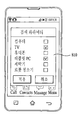
- FIG. 8 illustrates a screen provided to a user for designating a terminal category as a search parameter.
- the controller 180 may control a popup window 810 listing the terminal categories to be searched to be displayed on the display unit 151 in order to designate the terminal category as a search parameter.
- a computer, a TV, a mobile phone, a tablet PC, a washing machine, a robot cleaner, and the like are enumerated as terminal categories that may be designated as search parameters.
- these are merely examples for convenience of description and the items listed in FIG.
- various types of electronic devices such as a refrigerator, a navigation device, a lighting device, and a printer, may be set as search parameters.
- the controller 180 may set the category selected by the user as a search parameter and store the same in the memory 160 (in FIG. 8, the TV and the tablet PC are selected).
- the controller 180 may designate the TV and the tablet designated as the search parameters of FIG. 8 from the received neighbor device information. Information about TVs and tablets included in the category of a PC can be extracted. By using the search parameter, the user can easily determine whether the desired electronic device is located nearby, and can control so that only the truly necessary information is displayed on the device map.
- the controller 180 may extract the neighbor terminal 200 using the communication scheme specified as the search parameter from the received neighbor device information. For example, if the communication method specified by the search parameter is Wi-Fi, the controller 180 can extract an item supporting Wi-Fi communication from the neighbor device information.
- the controller 180 may be located within the separation distance specified by the search parameter from the received neighbor device information. ) Can be extracted. For example, if the separation distance specified by the search parameter is set to 50 m or less, the controller 180 can extract an item which is determined to be located within a radius of 50 m with respect to the mobile terminal 100 from neighboring device information. Referring to FIG. 6, the controller 180 generates a device map and stores the device map in the memory 160 based on the extracted neighbor terminal information (S705), and displays the generated device map on the display unit 151. Can be controlled. The device map is for displaying the neighboring terminal 200 belonging to the same place as the mobile terminal 100. The user selects the neighboring terminal 200 displayed on the device map, and the mobile terminal 100 and the neighboring terminal 200 are selected. ) Can be linked.
- the controller 180 may generate a device map by using the neighboring terminal information extracted in operation S704 and the place image received in operation S703.
- the device map will be described in detail with reference to the example of FIG. 9.
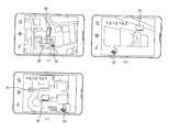
- FIGS. 9A through 9C are exemplary diagrams of a device map displayed through the mobile terminal 100.
- the controller 180 may generate a device map based on the place image received from the upper server 300.
- FIGS. 9A to 9C shows a device map based on a map image, which is an example of a place image, an image of a surrounding environment of the mobile terminal 100, and a blueprint of a place where the mobile terminal 100 is located. Illustrated as.
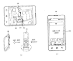
- the controller 180 may control the adjacent terminal 200 to be displayed on the place image (in FIGS. 9A to 9C, the adjacent terminal 200 may be a TV 201 or a notebook computer). (202)).
- the controller 180 may control the adjacent terminal 200 to be displayed through an icon.
- the location of the mobile terminal 100 may be controlled together with the adjacent terminal 200 on the device map.
- the position of the mobile terminal 100 does not necessarily need to be displayed and may be omitted by user setting.
- the controller 180 may control the location of the mobile terminal 100 not to be displayed on the device map.
- the controller 180 may visually distinguish the position of the mobile terminal 100 and the position of the neighboring terminal 200 on the device map. can do. For example, as illustrated in FIG. 9C, the controller 180 displays the position of the mobile terminal 100 in the form of a cursor 101, and displays the position of the neighboring terminal 200 in the form of an icon. The location of the terminal 100 and the adjacent terminal 200 may be visually distinguished. Visually distinguishing the positions of the mobile terminal 100 and the adjacent terminal 200 is to prevent the mobile terminal 100 displayed on the device map from being confused with the adjacent terminal 200.
- the controller 180 may display the location of the neighboring terminal 200 on the place image by using the location information of the neighboring terminal 200 included in the neighboring terminal information. However, when the location information is not included in the neighboring terminal information, the mobile terminal 100 may be arbitrarily displayed.
- 3 to 9 illustrate that the mobile terminal 100 receives the neighbor terminal information from the upper server 300 to create a device map, but the mobile terminal 100 must receive the neighbor terminal information from the upper server. It is not.
- the controller 180 directly neighbors the neighboring terminal 200. Terminal information can be received.
- the mobile terminal 100 may be provided with only the place image from the upper server 300, and the neighbor terminal information may be directly provided from the neighbor terminal information.
- FIG. 10 is an exemplary diagram of an ad-hoc network formed between the mobile terminal 100 and the adjacent terminal 200.
- the controller 180 of the mobile terminal 100 may broadcast a request signal for requesting neighbor terminal information through the wireless communication unit 110.
- the neighboring terminals 200 constituting the ad hoc network may provide neighboring terminal information to the mobile terminal 100 based on a request signal of the mobile terminal 100.
- the mobile terminal 100 may receive neighbor terminal information from a laptop, a desktop, a TV, a washing machine, a tablet PC, a robot cleaner, or the like forming an ad hoc network.
- the controller 180 may generate a device map based on the place image received from the upper server 300 and the neighbor terminal information received from the neighbor terminal 200.
- step S704 the filtering of the received neighbor device information by using the search parameter is not necessarily performed (S704). If all kinds of devices are designated as the search parameters, step S704 may be omitted.
- the controller 180 may provide the position of the mobile terminal 100 to the higher server 300 periodically (or aperiodically). If it is determined that the location of the mobile terminal 100 has been changed, the higher server 300 may provide the mobile terminal 100 with a place image corresponding to the updated location. Accordingly, the controller 180 can update the device map whenever the location of the mobile terminal 100 is changed.
- the mobile terminal 100 may receive neighboring terminal information periodically (or aperiodically) from the upper server 300. Accordingly, the controller 180 may update the device map whenever the neighboring terminal information is changed, and control the device map to display the neighboring terminal 200 in real time.
- the device map is displayed by displaying the location of the adjacent terminal 200 on the place image received from the upper server 300.
- the mobile terminal 100 necessarily displays the place image from the upper server 300. It does not have to be received. Even if the place image is not received from the upper server 300, the image input to the camera may be used as the place image.
- the controller 180 may control the display of the location of the adjacent terminal 200 using an augmented reality technology.
- the mobile terminal 100 may interwork with the neighboring terminal 200.
- the mobile terminal 100 may perform data communication with the neighboring terminal 200 to receive information provided by the neighboring terminal 200 or provide predetermined information to the neighboring terminal 200.
- the mobile terminal 100 may perform data communication with the neighbor terminal 200 through the neighbor terminal 200 address (IP and / or MAC address) included in the neighbor terminal information.
- IP and / or MAC address included in the neighbor terminal information.
- the mobile terminal 100 may be provided with an optimal service associated with a location where the mobile terminal 100 is located (ie, a network to which it belongs). For example, if the mobile terminal 100 is located in the art gallery, it may be linked with a computer operated in the art gallery to obtain information on the exhibited art, and if the mobile terminal 100 is located in the bus terminal, the bus terminal In conjunction with a computer operating in the network, it will be able to provide services such as bus operation information, bus ticket purchase. As another example, if the mobile terminal 100 is located at home, the mobile terminal 100 may be used as a remote controller for controlling various electronic devices constituting the home network. That is, the mobile terminal 100 of the present invention has an advantage of providing a user with a service suitable for the location of the mobile terminal 100 by configuring a device map suitable for a place where the mobile terminal 100 is located.
- the controller 180 may request access to the selected neighboring terminal 200 through the wireless communication unit 110.
- the mobile terminal 100 may access the neighboring terminal 200 to view or modify the shared file shared by the neighboring terminal 200, and may receive the shared file and store the shared file in its memory 160.
- the cloud computing service may be utilized by using the computing resources (software and hardware) provided by the adjacent terminal 200.
- 11A to 11C are exemplary diagrams for describing the mobile terminal 100 reading a shared file shared by the adjacent terminal 200.
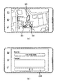
- the controller 180 may provide a list of shared files set to be shared through the notebook 202, as shown in FIG. 11B. If at least one of the list of shared files shown in FIG. 11B is selected, the controller 180 can control the display unit 151 to display a pop-up window 1110 as shown in FIG. 11C.
- the selected file may be executed by using the computing resource of the notebook 202.
- the mobile terminal 100 may receive image data according to file execution from the notebook 202.
- the controller 180 may control the image data received through the wireless communication unit 110 to be output through the display unit 151.
- a user of the mobile terminal 100 may be provided with a clouding service that remotely receives a result of the operation while performing a program operation through the hardware resource of the notebook 202.
- the mobile terminal 100 may receive the selected shared file from the notebook 202.
- the controller 180 may store the shared file received through the wireless communication unit 110 in the memory 160. On the contrary, the file stored in the mobile terminal 100 may be transmitted to the notebook.
- the controller 180 can transmit a control message to delete the selected shared file to the notebook 202 through the wireless communication unit 110.
- the notebook 202 may receive a control message and delete the selected shared file.
- the mobile terminal 100 may share a file with the selected neighbor terminal 200. Further, by using the hardware and software resources of the neighbor terminal 200, it is also possible to create a cloud computing environment using the neighbor terminal 200.
- FIG. 11 is for explaining that file sharing may be performed between the mobile terminal 100 and the adjacent terminal 200, but not for limiting the present invention.
- the file sharing is performed between the notebook 202 and the mobile terminal 100, but in addition to the notebook, it may be linked with various electronic devices including a storage device such as a tablet PC, a smart phone, and a smart TV.
- a storage device such as a tablet PC, a smart phone, and a smart TV.
- FIG. 11C the items listed in the popup window are selected to execute, copy, and delete the shared file.
- this is merely an example screen for convenience of description. The screen may be configured differently from FIG. 11C.
- the mobile terminal 100 may be set to output the same screen as the screen output from the neighboring terminal 200.
- FIG. 12A and 12B are exemplary diagrams for describing that the mobile terminal 100 outputs the same screen as the neighboring terminal 200.
- the mobile terminal 100 may receive image data from the TV 211 in real time.
- the controller 180 controls the image data received in real time from the TV 211 to be output through the display unit 151.
- the mobile terminal 100 and the TV 211 display the same screen. It is possible to provide a user with a multi screen environment for outputting.
- FIG. 12B illustrates that the mobile terminal 100 receives only image data of the neighboring terminal 200, not only video data but also audio data may be received from the neighboring terminal 200.
- the mobile terminal 100 and the adjacent terminal 200 do not necessarily output the same screen, and the screen of the TV 211 may be turned off while an image is output from the mobile terminal 100.
- the user has an advantage of viewing the TV through the mobile terminal 100 which is not provided with the broadcast receiving module.
- the mobile terminal 100 may receive and play voice data from the voice output device.
- FIG. 12 illustrates that a multi-screen environment is configured through the TV 211
- the present invention may be applied not only to the TV 211 but also to an image output device such as a tablet PC, a smartphone, a computer, a DVD player, and the like. to be.
- the mobile terminal 100 may control the operation of the adjacent terminal 200 provided through the device map.
- the mobile terminal 100 may control power of the neighboring terminal 200 or control the neighboring terminal 200 to perform a predetermined function. Control of the operation of the adjacent terminal 200 by the mobile terminal 100 will be described in more detail with reference to the example of FIG. 13.
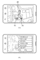
- FIG. 13A and 13B are exemplary diagrams for describing an operation of controlling the operation of the adjacent terminal 200 through the mobile terminal 100. If any one of the list of neighboring terminals 200 provided through the device map illustrated in FIG. 13A is selected (the TV 221 is selected in FIG. 13A), the controller 180 is as shown in FIG. 13B, The display unit 151 may be controlled to display an operation state of the selected neighboring terminal 200. For example, when the neighboring terminal 200 selected by the user is the TV 221 as shown in FIG. 13A, the controller 180 outputs an operation state of the TV 221 using the neighboring terminal information received from the TV 221.
- the touch screen can be controlled to In FIG. 13B, not only the power on / off state of the TV 221 but also channel information output through the TV, volume information of the TV, and the like are displayed.
- the user may not only control the power on / off of the TV 221 through the screen provided as shown in FIG. 13B, but also adjust a channel and a volume output through the TV 221. For example, in the example of FIG. 13B, when the user changes the channel output through the TV 221 from 6 to 11, the channel output through the TV 221 may also be adjusted from 6 to 11.
- the controller 180 may generate a control message for controlling the operation of the neighbor terminal 200 and then transmit the generated control message to the neighbor terminal 200 through the wireless communication unit 110.
- the mobile terminal 100 may be utilized as a remote controller that can control the operation of the neighbor terminal 200.
- the operation of the TV 221 is controlled through the mobile terminal 100, but the operation of various electronic devices as well as the TV may be controlled.
- the operation of the washing machine can be controlled remotely, the refrigerator (or freezing) temperature of the refrigerator can be adjusted, and the on / off of the lighting device can be controlled remotely.
- the operation of various electronic devices can be controlled.
- the mobile terminal 100 may be set to generate the second event. That is, when the first event occurs in the adjacent terminal 200, the second event may be controlled to be generated through the mobile terminal 100 to inform the fact of the first event.
- the first event occurs in the neighboring terminal 200 and the second event occurs in the mobile terminal 100 will be described in detail with reference to FIG. 14.
- 14A to 14C are exemplary diagrams for describing that the first event occurs in the adjacent terminal 200 and the second event occurs in the mobile terminal 100.
- a second event may occur in the mobile terminal 100 by chaining with a first event occurring in the neighboring terminal 200.
- the VOIP phone 232 illustrated in FIG. 14A when the VOIP phone 232 illustrated in FIG. 14A is selected as the neighboring terminal 200, when the first event occurs in the VOIP phone 232, the second event occurs in the mobile terminal 100 in connection with the first event. Can be set.
- the VOIP phone 232 may transmit an event message for notifying that the call signal has been received by the mobile terminal 100. have.
- the controller 180 controls the ringer to ring through the sound output module (or vibrating motor) to inform the VOIP phone 232 that the call signal has been received, as shown in FIG. 14C.
- the display unit 151 may be controlled to output a notification message indicating that the first event has occurred (second event).
- second event By outputting the ringtone and the notification message, the user can recognize that the call signal has been received through the VOIP phone 232.
- the controller 180 controls to make a call and at the same time, voice data provided to the VOIP phone 232 is transmitted to the mobile terminal 100.
- a control message for controlling the VOIP phone 232 to be relayed may be generated and provided to the VOIP phone 232.
- the first event occurs in the neighboring terminal 200 and the second event occurs in the mobile terminal 100 so as to generate a second event. It can be easily recognized that the first event has occurred.
- the VOIP phone 232 is described as an example, but the mobile terminal 100 of the present invention can be linked to various electronic devices in addition to the VOIP phone 232.
- first event when the washing of the washing machine is finished (first event), when scheduled recording is started (or terminated) on the TV (first event), or when an interruption occurs during the printer operation (first event).
- first event when the washing of the washing machine is finished (first event), when scheduled recording is started (or terminated) on the TV (first event), or when an interruption occurs during the printer operation (first event).
- the second event may occur in the mobile terminal 100 in connection with the first event that occurs.
- the event occurs in the mobile terminal 100 after the event occurs in the neighboring terminal 200 and chained thereto.
- the adjacent terminal It is also possible to set the second event to occur at 200.
- a ringtone may be set to ring in the VOIP telephone of FIG. 14.
- the controller 180 may generate an event message for notifying the fact that the first event has occurred, and then transmit the event message to the adjacent terminal 200 through the wireless communication unit 110.
- the neighbor terminal 200 receiving the event message may generate a second event for notifying that the first event has occurred in the mobile terminal 100.
- the mobile terminal 100 may transmit a text message (SMS, LMS or MMS) or an instant message to at least some of the adjacent terminals 200 provided through the device map.
- SMS text message
- LMS Long Term Evolution
- MMS multimedia subsystem
- 15A and 15B are exemplary diagrams for describing transmitting a text message or an instant message to the adjacent terminal 200 through the mobile terminal 100.
- a user may select at least one neighboring terminal 200 to which a text message or an instant message is to be transmitted.
- the controller 180 can execute a messaging application for creating a text message or an instant message, as shown in FIG. 15B.
- the controller 180 determines that the adjacent terminal (the tablet PC 241 is selected in FIG. 15A) in which the user-written message is selected in FIG. 15A. It can be controlled to be transmitted to).
- the user by providing a message to at least one neighboring terminal 200 through the mobile terminal 100, the user is expected to belong to a similar location, that is, belong to the same network cell as the user and put them in the same environment.
- the notification message may be provided to the unspecified counterpart.
- the mobile terminal 100 may be used as an in-house messenger.
- an advertiser who wants to perform a location-based advertisement may maximize a advertising effect by extracting a device located in a place where an advertisement is needed and transmitting an advertisement message.
- the message can be transmitted using either a text message or an instant message, but the neighboring terminal 200 is connected to the tablet PC 241 shown in FIG. 5A. If the number resource is not allocated together, the instant message may be used to send the message. However, when using an instant message, an application for transmitting and receiving instant messages should be installed in the mobile terminal 100 and the adjacent terminal 200.
- FIG. 15B illustrates that a messaging application for composing a text message or an instant message is executed, the messaging application does not necessarily have to be executed.
- the controller 180 may transmit a message previously stored in the memory 160 to the neighboring terminal 200 without a text message or an instant message writing process.
- FIG. 16A and 16B are exemplary diagrams for describing a case in which the above-described embodiments 1 to 6 are used in a combined form in one mobile terminal 100.
- the controller 180 selects the selected neighbor as shown in FIG. 16B.
- the list of services that can be provided through the terminal 200 may be listed. If any one of the service lists listed in FIG. 16B is selected, the controller 180 may control the selected service to be performed.
- 'view shared file' may be understood to perform the first embodiment
- 'multi screen' may be understood to perform the second embodiment
- the 'remote control' displayed in the pop-up window is for performing the third embodiment
- the 'device interworking' is for performing the fourth and / or fifth embodiments.
- 'message transmission' is for carrying out the sixth embodiment.
- the information of the adjacent device may be provided through the display unit 151.
- the neighbor device information may indicate a communication method supported by the neighbor device, a distance spaced apart from the mobile terminal 100, and the like.
- the pop-up window shown in FIG. 16B is merely an example for combining the first to fifth embodiments, and the first to sixth embodiments may not be combined through the pop-up window of FIG. 13.
- 16B may be set to be used in combination through the screen configuration different from that of FIG. 16B, and at least some of the first to sixth embodiments may be set to be used in combination.
- the mobile terminal 100 according to the present invention may access another mobile terminal 100 and use a device map provided by another mobile terminal 100.
- each is referred to as 'first mobile terminal 100' and 'second mobile terminal 100'. Let's do it.
- the first mobile terminal 100 may use the device map created based on the network cell to which the second mobile terminal 100 belongs after connecting to the second mobile terminal 100.
- the first mobile terminal 100 and the second mobile terminal 100 do not need to belong to the same place.
- the first mobile terminal 100 can access the second mobile terminal 100 using the phone number or IP / MAC address of the second mobile terminal 100.
- the controller 180 of the first mobile terminal 100 requests a connection to the second mobile terminal 100 through a wireless Internet communication network (or a mobile communication network). Can be.
- the second mobile terminal 100 may provide a device map to the first mobile terminal 100.
- a user of the first mobile terminal 100 may receive various services from neighboring terminals 200 belonging to the same place as the second mobile terminal 100 based on the device map received from the second mobile terminal 100. have.
- the mobile terminal 100 may build up a device map database by accumulating and storing it in the memory 160 whenever a device map is generated.
- a user can load a device map that has been created at a pre-experienced place at any time and access adjacent devices around the pre-experienced place.
- the mobile terminal 100 may generate a first device map and store it in the memory 160. Thereafter, even when the mobile terminal 100 moves to a second place different from the first place, the user may load the first device map to access the adjacent terminal 200 in the first place.
- the mobile terminal 100 may receive a device map from a device map database of another mobile terminal 100 and output a device map of a place previously experienced by the other mobile terminal 100.
- the mobile terminal 100 may detect the surrounding environment of the mobile terminal 100 and control the display of the adjacent terminal 200 on the device map to be adjusted. For example, when the mobile terminal 100 is located inside a vehicle traveling on a road, the mobile terminal 100 may control an icon indicating an adjacent device to change into an automobile shape.
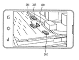
- FIG. 17 is an exemplary diagram of a device map when the mobile terminal 100 is present inside a vehicle traveling on a road.
- the controller 180 may control the adjacent terminal 200 to be displayed using the vehicle icon. That is, in FIG. 17, the user may recognize that three adjacent terminals 200 are located at the same place as the mobile terminal 100.
- the controller 180 may determine that the mobile terminal 100 is located inside a vehicle traveling on a road. have. In this case, as illustrated in FIG. 17, the controller 180 may control the positions of the mobile terminal 100 and the adjacent terminal 200 to be displayed by the vehicle icons 261-263.
- the controller 180 may control the UI of the device map to be adjusted to suit the surrounding environment of the mobile terminal 100.
- the mobile terminal 100 when a vehicle accident occurs in the adjacent terminal 200 (first event occurs), the mobile terminal 100 receives an event message informing of the fact that the vehicle accident occurred from the adjacent terminal 200. Can be.
- the controller 180 may output an alarm sound indicating that a vehicle accident has occurred in the vicinity or control an alarm message to be displayed (second event occurrence). ).
- the controller 180 may transmit an event message for notifying the fact that the vehicle accident occurred to the adjacent terminal 200 displayed on the device map.
- the adjacent terminal 200 receiving the event message may output an alarm sound or control the alarm message to be displayed (the second event occurs).
- the controller 180 may suddenly decrease the speed of the mobile terminal 100 detected through GPS, or the acceleration of the mobile terminal 100 detected through the sensing unit 140 (specifically, an acceleration sensor). If the degree of reduction or the intensity of the impact delivered to the mobile terminal 100 is greater than or equal to a preset level, it may be determined that an accident has occurred in the vehicle.
- the user may recognize the road situation information in real time and immediately recognize the accident occurrence information by exchanging a text message or an instant message with the adjacent terminal 200 displayed on the device map.
- the present invention described above can be embodied as computer readable codes on a medium in which a program is recorded.
- the computer-readable medium includes all kinds of recording devices in which data that can be read by a computer system is stored. Examples of computer-readable media include ROM, RAM, CD-ROM, magnetic tape, floppy disks, optical data storage devices, and the like, which are also implemented in the form of carrier waves (eg, transmission over the Internet). It also includes.
- the computer may include the controller 180 of the terminal.
- the mobile terminal and its control method according to the present invention can be applied to a wireless communication system utilizing a wireless communication technology such as Bluetooth, CDMA, 3GGP LTE, LTE-A, IEEE802.
- a wireless communication technology such as Bluetooth, CDMA, 3GGP LTE, LTE-A, IEEE802.
Landscapes
- Engineering & Computer Science (AREA)
- Computer Networks & Wireless Communication (AREA)
- Signal Processing (AREA)
- Telephone Function (AREA)
- Mobile Radio Communication Systems (AREA)
- Databases & Information Systems (AREA)
Abstract
Description
Claims (24)
- 이동 단말기의 위치를 감지하고,상기 이동 단말기의 위치에 대응하는 장소 이미지와 상기 이동 단말기와 동일한 장소에 놓인 적어도 하나의 인접 단말기에 관한 인접 단말기 정보를 외부로부터 수신하는 무선 통신부;상기 장소 이미지와 상기 인접 단말기 정보를 기초로, 상기 이동 단말기와 동일한 장소에 놓인 상기 인접 단말기를 표시하기 위한 디바이스 맵을 생성하는 제어부;상기 디바이스 맵을 저장하는 메모리; 및상기 디바이스 맵을 디스플레이하기 위한 디스플레이부를 포함하는 이동 단말기.
- 제 1 항에 있어서,상기 인접 단말기 정보는 상기 이동 단말기로부터 소정 이격 거리 이내 위치하는 상기 인접 단말기와 대응하는 것을 특징으로 하는 이동 단말기.
- 제 1 항에 있어서,상기 인접 단말기 정보는 상기 무선 통신부와 동일한 네트워크 셀에 소속되는 상기 인접 단말기와 대응하는 것을 특징으로 하는 이동 단말기.
- 제 3 항에 있어서,상기 인접 단말기 정보는 상기 무선 통신부와 동일한 액세스 포인트에 접속하고 있는 상기 인접 단말기와 대응하는 것을 특징으로 하는 이동 단말기.
- 제 3 항에 있어서,상기 인접 단말기 정보는 상기 무선 통신부와 동일한 기지국 또는 동일한 펨토셀에 접속하고 있는 상기 인접 단말기와 대응하는 것을 특징으로 하는 이동 단말기.
- 제 1 항에 있어서,상기 메모리는 검색 파라미터를 더 저장하고,상기 제어부는 상기 검색 파라미터를 이용하여 상기 인접 디바이스 정보를 필터링 하고,상기 필터링된 인접 디바이스 정보를 이용하여 상기 디바이스 맵을 생성하는 것을 특징으로 하는 이동 단말기.
- 제 6 항에 있어서,상기 검색 파라미터는 단말기 카테고리를 지정한 것이고,상기 제어부는 상기 인접 디바이스가 상기 검색 파라미터가 정하는 단말기 카테고리로 분류되는지 판단하여 상기 인접 디바이스 정보를 필터링 하는 것을 특징으로 하는 이동 단말기.
- 제 6 항에 있어서,상기 검색 파라미터는 단말기 통신 방식을 지정한 것이고,상기 제어부는 상기 인접 디바이스가 상기 검색 파라미터가 정하는 통신 방식을 지원하는지 여부를 판단하여 상기 인접 디바이스 정보를 필터링 하는 것을 특징으로 하는 이동 단말기.
- 제 6 항에 있어서,상기 검색 파라미터는 이격 거리에 관한 것이고,상기 제어부는 상기 인접 디바이스가 상기 이격 거리 이내에 위치하는지 여부를 판단하여 상기 인접 디바이스 정보를 필터링 하는 것을 특징으로 하는 이동 단말기.
- 제 1 항에 있어서,상기 제어부는 상기 장소 이미지 위에 상기 인접 단말기의 위치를 표시하여 상기 디바이스 맵을 생성하는 것을 특징으로 하는 이동 단말기.
- 제 10 항에 있어서,상기 제어부는 상기 장소 이미지 위에 상기 이동 단말기의 위치를 더 표시하여 상기 디바이스 맵을 생성하는 것을 특징으로 하는 이동 단말기.
- 제 11 항에 있어서,상기 제어부는 상기 이동 단말기의 위치와 상기 인접 단말기의 위치가 시각적으로 구분되도록 제어하는 것을 특징으로 하는 이동 단말기.
- 제 12 항에 있어서,상기 제어부는 커서(cursor)를 이용하여 상기 이동 단말기의 위치를 표시하고, 아이콘을 이용하여 상기 인접 단말기의 위치를 표시하는 것을 특징으로 하는 이동 단말기.
- 제 10 항에 있어서,상기 장소 이미지는 상기 이동 단말기의 위치에 대응하는 지도 이미지인 것을 특징으로 하는 이동 단말기.
- 제 1 항에 있어서,상기 디바이스 맵에 표시되는 상기 인접 단말기 중 적어도 하나가 선택되면,상기 제어부는 상기 선택된 인접 단말기와 데이터 통신을 수행하는 것을 특징으로 하는 이동 단말기.
- 제 15 항에 있어서,상기 제어부는 상기 인접 단말기로부터 상기 인접 단말기가 공유하는 공유 파일이 수신되도록 상기 무선 통신부를 제어하는 것을 특징으로 하는 이동 단말기.
- 제 1 항에 있어서,상기 디바이스 맵에 표시되는 상기 인접 단말기 중 적어도 하나가 선택되면,상기 무선 통신부는 상기 선택된 인접 단말기로부터 영상 데이터를 수신하고,상기 제어부는 상기 영상 데이터가 디스플레이되도록 상기 디스플레이부를 제어하는 것을 특징으로 하는 이동 단말기.
- 제 1 항에 있어서,상기 무선 통신부는 상기 디바이스 맵에 표시되는 상기 인접 단말기 중 적어도 하나로부터 제1 이벤트 발생 메시지를 수신하는 것을 특징으로 하는 이동 단말기.
- 제 18 항에 있어서,상기 제1 이벤트 발생 메시지가 수신되면, 상기 제어부는 상기 제1 이벤트 발생을 알리기 위한 제2 이벤트가 발생되도록 제어하는 것을 특징으로 하는 이동 단말기.
- 제 19 항에 있어서,상기 제2 이벤트는 알람음의 출력 및 알람 메시지의 표시 중 적어도 하나인 것을 특징으로 하는 이동 단말기.
- 제 1 항에 있어서,상기 디바이스 맵에 표시되는 상기 인접 단말기 중 적어도 하나가 선택되면,상기 제어부는 상기 선택된 인접 단말기의 동작 상태가 표시되도록 상기 디스플레이부를 제어하는 것을 특징으로 하는 이동 단말기.
- 제 21 항에 있어서,상기 제어부는 상기 선택된 인접 단말기의 동작을 제어하기 위한 제어 메시지를 생성하고,상기 제어 메시지가 상기 선택된 인접 단말기로 전송되도록 상기 무선 통신부를 제어하는 것을 특징으로 하는 이동 단말기.
- 제 22 항에 있어서,상기 제어 메시지는 상기 인접 단말기의 파워 온오프를 제어하기 위한 것임을 특징으로 하는 이동 단말기.
- (a) 이동 단말기의 위치를 감지하는 단계;(b) 상기 이동 단말기의 위치에 대응하는 장소 이미지를 수신하고, 상기 이동 단말기와 동일한 장소에 놓인 적어도 하나의 인접 단말기에 관한 인접 단말기 정보를 수신하는 단계; 및(c) 상기 장소 이미지와 상기 인접 단말기 정보를 이용하여 디바이스 맵을 생성하는 단계를 포함하는 이동 단말기의 제어 방법.
Priority Applications (2)
| Application Number | Priority Date | Filing Date | Title |
|---|---|---|---|
| US14/114,491 US9867025B2 (en) | 2011-04-28 | 2012-04-30 | Mobile terminal and method for controlling same |
| KR1020137030244A KR101611964B1 (ko) | 2011-04-28 | 2012-04-30 | 이동 단말기 및 그 제어 방법 |
Applications Claiming Priority (2)
| Application Number | Priority Date | Filing Date | Title |
|---|---|---|---|
| US201161480351P | 2011-04-28 | 2011-04-28 | |
| US61/480,351 | 2011-04-28 |
Publications (2)
| Publication Number | Publication Date |
|---|---|
| WO2012148242A2 true WO2012148242A2 (ko) | 2012-11-01 |
| WO2012148242A3 WO2012148242A3 (ko) | 2013-03-07 |
Family
ID=47072964
Family Applications (1)
| Application Number | Title | Priority Date | Filing Date |
|---|---|---|---|
| PCT/KR2012/003362 Ceased WO2012148242A2 (ko) | 2011-04-28 | 2012-04-30 | 이동 단말기 및 그 제어 방법 |
Country Status (3)
| Country | Link |
|---|---|
| US (1) | US9867025B2 (ko) |
| KR (1) | KR101611964B1 (ko) |
| WO (1) | WO2012148242A2 (ko) |
Cited By (5)
| Publication number | Priority date | Publication date | Assignee | Title |
|---|---|---|---|---|
| WO2014138604A1 (en) * | 2013-03-08 | 2014-09-12 | Google Inc. | Proximity detection by mobile devices |
| EP2890059A1 (en) * | 2013-12-31 | 2015-07-01 | Samsung Electronics Co., Ltd | Display apparatus and method for controlling and monitoring peripheral devices in a home network |
| WO2016021907A1 (ko) * | 2014-08-04 | 2016-02-11 | 넥시스 주식회사 | 웨어러블 디바이스를 이용한 정보처리 시스템 및 방법 |
| WO2016056814A1 (en) * | 2014-10-10 | 2016-04-14 | Samsung Electronics Co., Ltd. | Method and electronic device for displaying time |
| US9635433B2 (en) | 2013-03-08 | 2017-04-25 | Google Inc. | Proximity detection by mobile devices |
Families Citing this family (20)
| Publication number | Priority date | Publication date | Assignee | Title |
|---|---|---|---|---|
| JP5799883B2 (ja) * | 2011-06-16 | 2015-10-28 | コニカミノルタ株式会社 | 接続制御装置、情報処理装置、画像形成装置、携帯型移動端末、情報処理システム、接続制御装置の制御方法、及び接続制御装置の制御プログラム |
| CN103167464B (zh) * | 2011-12-09 | 2018-06-15 | 中兴通讯股份有限公司 | 触发更新移动节点映射信息的方法、ms和mn |
| KR102084630B1 (ko) * | 2012-07-26 | 2020-03-05 | 삼성전자주식회사 | 질문 메시지 전송 방법 및 이를 위한 디스플레이 장치, 정보 공유 방법 및 모바일 기기 |
| US20140111520A1 (en) | 2012-10-23 | 2014-04-24 | Bmc Software, Inc. | User-centric annotated location aware asset mapping |
| CN103105993B (zh) * | 2013-01-25 | 2015-05-20 | 腾讯科技(深圳)有限公司 | 基于增强现实技术实现互动的方法和系统 |
| US20140270284A1 (en) * | 2013-03-13 | 2014-09-18 | Aliphcom | Characteristic-based communications |
| US10149121B2 (en) | 2014-04-13 | 2018-12-04 | Lg Electronics Inc. | Method for managing D2D terminal group in wireless communication system and apparatus for same |
| KR102306709B1 (ko) * | 2014-08-19 | 2021-09-29 | 삼성전자주식회사 | 청소 로봇, 청소 로봇의 제어 장치, 제어 시스템, 및 제어 방법 |
| JP2017535001A (ja) * | 2014-08-25 | 2017-11-24 | アール・エフ・デジタル・コーポレイションRf Digital Corporation | プッシュユーザインターフェイス |
| US10275138B2 (en) * | 2014-09-02 | 2019-04-30 | Sonos, Inc. | Zone recognition |
| EP3281412B1 (en) | 2015-04-08 | 2021-08-25 | Sonos, Inc. | Location based playback system control |
| CN105228122A (zh) * | 2015-07-01 | 2016-01-06 | 深圳市美贝壳科技有限公司 | 相邻的多个安卓定制设备间的交流方法 |
| CN105120094B (zh) * | 2015-08-28 | 2016-11-09 | 努比亚技术有限公司 | 锁屏与解锁装置及方法 |
| CN105549944B (zh) * | 2015-12-11 | 2019-07-23 | 小米科技有限责任公司 | 设备显示方法及装置 |
| KR20180036169A (ko) * | 2016-09-30 | 2018-04-09 | 엘지전자 주식회사 | 디지털 디바이스 및 그 데이터 처리 방법 |
| US10798538B2 (en) | 2017-01-20 | 2020-10-06 | Bmc Software, Inc. | Asset floor map |
| JP6895084B2 (ja) * | 2017-12-26 | 2021-06-30 | 京セラドキュメントソリューションズ株式会社 | 画像形成システムおよび画像形成プログラム |
| US10629039B1 (en) * | 2018-12-14 | 2020-04-21 | Arlo Technologies, Inc. | Electronic monitoring system with geographic location |
| US11218838B2 (en) * | 2019-10-31 | 2022-01-04 | Snap Inc. | Focused map-based context information surfacing |
| US20240422511A1 (en) * | 2021-11-03 | 2024-12-19 | Interdigital Patent Holdings, Inc. | Methods and apparatus for supporting collaborative extended reality (xr) |
Family Cites Families (17)
| Publication number | Priority date | Publication date | Assignee | Title |
|---|---|---|---|---|
| US20140098247A1 (en) * | 1999-06-04 | 2014-04-10 | Ip Holdings, Inc. | Home Automation And Smart Home Control Using Mobile Devices And Wireless Enabled Electrical Switches |
| JP4487443B2 (ja) | 2001-05-29 | 2010-06-23 | 日本電気株式会社 | 位置情報表示システム及びその表示方法 |
| KR20050079379A (ko) | 2004-02-05 | 2005-08-10 | 김면식 | 위치기반 정보제공장치, 정보제공시스템 및 정보제공방법 |
| US7382271B2 (en) * | 2004-09-29 | 2008-06-03 | Siemens Building Technologies, Inc. | Automated position detection for wireless building automation devices |
| US7881733B2 (en) * | 2004-11-05 | 2011-02-01 | Wirelesswerx International, Inc. | Method and system to monitor and control devices utilizing wireless media |
| US8301159B2 (en) * | 2004-12-31 | 2012-10-30 | Nokia Corporation | Displaying network objects in mobile devices based on geolocation |
| US20070135135A1 (en) * | 2005-12-09 | 2007-06-14 | Kenneth Brown | Electronic equipment with content management function and program for providing same |
| EP2179574B1 (en) * | 2007-07-20 | 2018-09-05 | Nederlandse Organisatie voor toegepast- natuurwetenschappelijk onderzoek TNO | Identification of proximate mobile devices |
| KR101430452B1 (ko) * | 2007-10-15 | 2014-08-14 | 엘지전자 주식회사 | 통신 기기 및 이것의 위치 정보 제공 방법 |
| US8060018B2 (en) * | 2008-02-08 | 2011-11-15 | Yahoo! Inc. | Data sharing based on proximity-based ad hoc network |
| KR101545703B1 (ko) | 2009-01-12 | 2015-08-20 | 삼성전자 주식회사 | 이동단말의 위치정보를 활용한 위치 서비스 제공 및 수신방법 |
| KR101622087B1 (ko) | 2009-09-29 | 2016-05-18 | 엘지전자 주식회사 | 휴대 단말기 및 그 동작 제어방법 |
| KR20110024785A (ko) | 2009-09-03 | 2011-03-09 | 주식회사 리버트론 | 무선통신을 이용한 위치기반 영상/음성정보 서비스 시스템 |
| US20110065451A1 (en) * | 2009-09-17 | 2011-03-17 | Ydreams-Informatica, S.A. | Context-triggered systems and methods for information and services |
| US20110244878A1 (en) * | 2010-04-06 | 2011-10-06 | Seconca Holdings Limited | Identifying and Displaying User Status Information |
| KR101642997B1 (ko) | 2010-04-22 | 2016-07-26 | 엘지전자 주식회사 | 영상표시 시스템 및 이벤트 공유 방법 |
| US8937534B2 (en) * | 2010-12-08 | 2015-01-20 | At&T Intellectual Property I, L.P. | Remote control of electronic devices via mobile device |
-
2012
- 2012-04-30 WO PCT/KR2012/003362 patent/WO2012148242A2/ko not_active Ceased
- 2012-04-30 US US14/114,491 patent/US9867025B2/en not_active Expired - Fee Related
- 2012-04-30 KR KR1020137030244A patent/KR101611964B1/ko not_active Expired - Fee Related
Cited By (12)
| Publication number | Priority date | Publication date | Assignee | Title |
|---|---|---|---|---|
| WO2014138604A1 (en) * | 2013-03-08 | 2014-09-12 | Google Inc. | Proximity detection by mobile devices |
| CN104871516A (zh) * | 2013-03-08 | 2015-08-26 | 谷歌公司 | 由移动装置进行的接近度检测 |
| KR20150129646A (ko) * | 2013-03-08 | 2015-11-20 | 구글 인코포레이티드 | 이동 디바이스들에 의한 근접 검출 |
| JP2016519863A (ja) * | 2013-03-08 | 2016-07-07 | グーグル インコーポレイテッド | モバイルデバイスによる近接検出 |
| US9496968B2 (en) | 2013-03-08 | 2016-11-15 | Google Inc. | Proximity detection by mobile devices |
| US9635433B2 (en) | 2013-03-08 | 2017-04-25 | Google Inc. | Proximity detection by mobile devices |
| CN104871516B (zh) * | 2013-03-08 | 2019-08-13 | 谷歌有限责任公司 | 用于接近度检测的方法、移动装置和计算机可读媒体 |
| KR102145560B1 (ko) * | 2013-03-08 | 2020-08-18 | 구글 엘엘씨 | 이동 디바이스들에 의한 근접 검출 |
| EP2890059A1 (en) * | 2013-12-31 | 2015-07-01 | Samsung Electronics Co., Ltd | Display apparatus and method for controlling and monitoring peripheral devices in a home network |
| US11627013B2 (en) | 2013-12-31 | 2023-04-11 | Samsung Electronics Co., Ltd. | Display apparatus, terminal apparatus, and methods of controlling at least one peripheral device using same |
| WO2016021907A1 (ko) * | 2014-08-04 | 2016-02-11 | 넥시스 주식회사 | 웨어러블 디바이스를 이용한 정보처리 시스템 및 방법 |
| WO2016056814A1 (en) * | 2014-10-10 | 2016-04-14 | Samsung Electronics Co., Ltd. | Method and electronic device for displaying time |
Also Published As
| Publication number | Publication date |
|---|---|
| US20140087770A1 (en) | 2014-03-27 |
| WO2012148242A3 (ko) | 2013-03-07 |
| US9867025B2 (en) | 2018-01-09 |
| KR20140010157A (ko) | 2014-01-23 |
| KR101611964B1 (ko) | 2016-04-12 |
Similar Documents
| Publication | Publication Date | Title |
|---|---|---|
| WO2012148242A2 (ko) | 이동 단말기 및 그 제어 방법 | |
| WO2016208803A1 (en) | Deformable display device and operating method thereof | |
| WO2017099306A1 (en) | Flexible display device | |
| WO2015012449A1 (en) | Electronic device and control method thereof | |
| WO2015064876A1 (en) | Method for generating receipe information in mobile terminal | |
| WO2014175513A1 (en) | Mobile terminal and control method thereof | |
| WO2016208812A1 (en) | Flexible display device and operating method thereof | |
| WO2015046636A1 (ko) | 이동 단말기 및 이의 제어방법 | |
| WO2016010262A1 (en) | Mobile terminal and controlling method thereof | |
| WO2012050248A1 (ko) | 이동 단말기 및 그 제어 방법 | |
| WO2015064858A1 (ko) | 단말기 및 그 제어 방법 | |
| WO2016010221A1 (ko) | 이동 단말기 및 그 제어 방법 | |
| WO2017065361A1 (ko) | 플렉서블 디스플레이 장치 | |
| WO2017104941A1 (en) | Mobile terminal and method for controlling the same | |
| WO2012008628A1 (ko) | 이동단말기 및 그 대기화면 구성방법 | |
| WO2017094926A1 (ko) | 단말 장치 및 제어 방법 | |
| WO2018026059A1 (ko) | 이동 단말기 및 그 제어방법 | |
| WO2014030956A1 (en) | Apparatus for uploading contents, user terminal apparatus for downloading contents, server, contents sharing system and their contents sharing method | |
| WO2012046891A1 (ko) | 이동단말기, 디스플레이 장치 및 그 제어 방법 | |
| WO2015060501A1 (ko) | 이동 단말기의 제어 장치 및 그 방법 | |
| WO2016056723A1 (en) | Mobile terminal and controlling method thereof | |
| WO2014010874A1 (ko) | 이동 단말기 및 그것의 제어 방법 | |
| WO2016190479A1 (ko) | 변형 가능한 디스플레이 장치 및 그의 동작 방법 | |
| WO2014123306A1 (en) | Mobile terminal and control method thereof | |
| WO2017039103A1 (ko) | 이동 단말기 및 그의 제어 방법 |
Legal Events
| Date | Code | Title | Description |
|---|---|---|---|
| 121 | Ep: the epo has been informed by wipo that ep was designated in this application |
Ref document number: 12776838 Country of ref document: EP Kind code of ref document: A2 |
|
| NENP | Non-entry into the national phase |
Ref country code: DE |
|
| ENP | Entry into the national phase |
Ref document number: 20137030244 Country of ref document: KR Kind code of ref document: A |
|
| WWE | Wipo information: entry into national phase |
Ref document number: 14114491 Country of ref document: US |
|
| 122 | Ep: pct application non-entry in european phase |
Ref document number: 12776838 Country of ref document: EP Kind code of ref document: A2 |