WO2012153376A1 - Système informatique et procédé de traitement d'informations - Google Patents
Système informatique et procédé de traitement d'informations Download PDFInfo
- Publication number
- WO2012153376A1 WO2012153376A1 PCT/JP2011/060591 JP2011060591W WO2012153376A1 WO 2012153376 A1 WO2012153376 A1 WO 2012153376A1 JP 2011060591 W JP2011060591 W JP 2011060591W WO 2012153376 A1 WO2012153376 A1 WO 2012153376A1
- Authority
- WO
- WIPO (PCT)
- Prior art keywords
- user
- job
- information
- server
- requested
- Prior art date
- Legal status (The legal status is an assumption and is not a legal conclusion. Google has not performed a legal analysis and makes no representation as to the accuracy of the status listed.)
- Ceased
Links
Images




Classifications
-
- G—PHYSICS
- G06—COMPUTING OR CALCULATING; COUNTING
- G06F—ELECTRIC DIGITAL DATA PROCESSING
- G06F9/00—Arrangements for program control, e.g. control units
- G06F9/06—Arrangements for program control, e.g. control units using stored programs, i.e. using an internal store of processing equipment to receive or retain programs
- G06F9/46—Multiprogramming arrangements
- G06F9/48—Program initiating; Program switching, e.g. by interrupt
- G06F9/4806—Task transfer initiation or dispatching
- G06F9/4843—Task transfer initiation or dispatching by program, e.g. task dispatcher, supervisor, operating system
-
- G—PHYSICS
- G06—COMPUTING OR CALCULATING; COUNTING
- G06F—ELECTRIC DIGITAL DATA PROCESSING
- G06F11/00—Error detection; Error correction; Monitoring
- G06F11/30—Monitoring
- G06F11/34—Recording or statistical evaluation of computer activity, e.g. of down time, of input/output operation ; Recording or statistical evaluation of user activity, e.g. usability assessment
- G06F11/3438—Recording or statistical evaluation of computer activity, e.g. of down time, of input/output operation ; Recording or statistical evaluation of user activity, e.g. usability assessment monitoring of user actions
-
- G—PHYSICS
- G06—COMPUTING OR CALCULATING; COUNTING
- G06F—ELECTRIC DIGITAL DATA PROCESSING
- G06F2209/00—Indexing scheme relating to G06F9/00
- G06F2209/50—Indexing scheme relating to G06F9/50
- G06F2209/5013—Request control
-
- G—PHYSICS
- G06—COMPUTING OR CALCULATING; COUNTING
- G06F—ELECTRIC DIGITAL DATA PROCESSING
- G06F2209/00—Indexing scheme relating to G06F9/00
- G06F2209/50—Indexing scheme relating to G06F9/50
- G06F2209/5021—Priority
-
- G—PHYSICS
- G06—COMPUTING OR CALCULATING; COUNTING
- G06F—ELECTRIC DIGITAL DATA PROCESSING
- G06F2209/00—Indexing scheme relating to G06F9/00
- G06F2209/50—Indexing scheme relating to G06F9/50
- G06F2209/508—Monitor
-
- G—PHYSICS
- G06—COMPUTING OR CALCULATING; COUNTING
- G06F—ELECTRIC DIGITAL DATA PROCESSING
- G06F9/00—Arrangements for program control, e.g. control units
- G06F9/06—Arrangements for program control, e.g. control units using stored programs, i.e. using an internal store of processing equipment to receive or retain programs
- G06F9/46—Multiprogramming arrangements
- G06F9/50—Allocation of resources, e.g. of the central processing unit [CPU]
- G06F9/5005—Allocation of resources, e.g. of the central processing unit [CPU] to service a request
- G06F9/5027—Allocation of resources, e.g. of the central processing unit [CPU] to service a request the resource being a machine, e.g. CPUs, Servers, Terminals
Definitions
- the present invention relates to a computer system, and more particularly to a computer system that determines job priority.
- the client-server type system needs to schedule execution of a job instructed to start by the user.
- the conventional method for scheduling job execution is to detect whether a user is seated by a human sensor, and execute a job instructed to start if it is determined that the user is away.
- a method of not executing a job instructed to start is proposed (for example, see Patent Document 1).
- Patent Document 1 controls a job based on only two stages of whether the user is away or seated, the job cannot be accurately scheduled according to the degree of attention (attention level) of the user's job. .
- the priority of the job that defines the mutual relationship between the plurality of jobs is not taken into consideration, and therefore the priority of the job cannot be finely controlled.
- Patent Literature 2 and Patent Literature 3 can dynamically change the priority between a plurality of jobs, but the priority is given in consideration of the computer resources used and the time limit for executing the job. Therefore, the job cannot be scheduled according to the user's attention to the job.
- the present invention has been made for such a problem, and an object of the present invention is to automatically acquire a degree of attention to a user's job and to schedule a job accurately according to the obtained degree of attention. Is an offer.
- a computer comprising at least one terminal used by at least one user, a server connected to each terminal, and at least one monitoring device that measures the state of each user.
- the monitoring device measures first information indicating whether or not the user is present in front of the terminal, and transmits a measurement result including the first information to the server. Then, the terminal requests the server to start the job instructed by the user, requests the server for the progress status of the job inquired by the user, and the server requests the start.
- Second information including the job that has been executed, the user who has requested the start of the job, the number of requests for the progress status of the job, and the user who has requested the progress of the job And holding the user's attention level for the job based on the transmitted measurement result and the second information, and prioritizing the job requested to start according to the calculated attention level. Determine the degree.
- the priority of a job can be determined according to the degree of attention to the user's job.
- the computer system acquires the degree (attention level) that a user who requests job execution pays attention to the job, and determines the priority of the job according to the acquired attention level.
- FIG. 1 is a block diagram showing a configuration of a computer system according to the first embodiment of this invention.
- the computer system according to the first embodiment of the present invention has a plurality of information processing apparatuses connected to a network.
- the information processing apparatus of this embodiment is a computer.
- the plurality of information processing apparatuses include at least one user terminal 101, a server 107, and at least one user state monitoring apparatus 105.
- the user terminal 101 is a client of the server 107.
- the server 107 is a device that receives a job request from the user terminal 101 and processes the job.
- the user status monitoring device 105 is a device that monitors the status of a user who uses the user terminal 101.
- the user terminal 101 and the server 107 are computers having an OS (Operating System, hereinafter the same).
- User terminal 101 communicates with at least one user state monitoring device 105.
- the server 107 communicates with a plurality of user terminals 101.
- FIG. 2 is a block diagram illustrating a physical configuration of the information processing apparatus according to the first embodiment of this invention.
- the server 107 and the user terminal 101 are information processing apparatuses including a memory 202, a processor 201, an external storage device 203, and a communication device 204.
- the user state monitoring apparatus 105 is an information processing apparatus including at least a memory 202, a processor 201, and a communication device 204.
- the processor 201 is an arithmetic device such as a CPU, and may include a plurality of processors.
- the memory 202 is a primary storage area.
- the processor 201 reads a program into the memory 202 and executes the read program, thereby implementing functions to be described later of each information processing apparatus.
- the communication device 204 is a network interface such as a NIC, and may include an antenna for wireless communication. Each information processing apparatus communicates via the communication apparatus 204 which each has.
- the operator or the like stores a program or the like in the external storage device 203 in the server 107, the user terminal 101, and the user state monitoring device 105.
- the processor 201 executes a program stored in the external storage device 203 by the OS included in each information processing device, the program stored in the external storage device 203 is read into the memory 202. For this reason, a program group described later is described as being stored in the memory 202 of each information processing apparatus.
- the user state monitoring device 105 includes a device that measures a user state such as a camera, a human sensor, or a seating sensor. Thereby, the user state monitoring apparatus 105 can acquire information necessary for determining whether or not the user is present in front of the display of the user terminal 101.
- the camera included in the user state monitoring apparatus 105 is, for example, a Web camera.
- the user state monitoring apparatus 105 can photograph the facial expression of the user. Further, when the user condition monitoring device 105 includes a human sensor that detects body temperature or frequency, the user condition monitoring device 105 can measure the user's body temperature, the user's body movement, or the like. Moreover, when the user state monitoring apparatus 105 has a seating sensor, the user state monitoring apparatus 105 can measure whether the user is present.
- the user state monitoring device 105 When the user state monitoring device 105 includes a human sensor that can measure a user's body movement, the user state monitoring device 105 acquires a camera or a seating sensor in order to acquire whether or not the user is present, It has a human sensor. Further, the user state monitoring apparatus 105 may include a plurality of sensors that measure the user state.
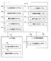
- the server 107 includes a job request reception program 108, a progress status response program 109, a priority update program 110, a job processing program 111, a user status reception program 112, a user status table 113, a progress request count table 114, an executable job table 115, And an executing job table 116.
- the job request reception program 108 has a function for receiving a job execution request transmitted from the user terminal 101.
- the progress status response program 109 has a function for transmitting the job progress status to the user terminal 101.
- the priority update program 110 has a function for changing the priority of a job.
- the job processing program 111 has a function for processing a job.
- the user status reception program 112 has a function for receiving information (hereinafter referred to as user status information) indicating a user status transmitted from the user status monitoring device 105.
- the user status table 113 is a table in which user status information is stored.
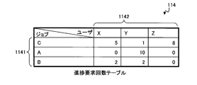
- the progress request count table 114 is a table that stores the number of times the job progress has been requested from the user terminal 101.
- the executable job table 115 is a table in which information indicating whether a job can be executed by the user terminal 101 is stored.
- the in-execution job table 116 is a table in which information indicating the job being executed is stored.
- the user terminal 101 has a user status notification program 102, a job execution request program 103, and a progress status request program 104.
- the user status notification program 102 has a function for transmitting user status information transmitted from the user status monitoring device 105 to the server 107.
- the job execution request program 103 has a function for requesting job execution.
- the progress status request program 104 has a function for requesting the server 107 to transmit the progress status of the job.
- the user status monitoring device 105 has a user status response program 106.
- the user status response program 106 has a function for transmitting user status information to the server 107 when user status information is requested from the server 107.
- the user status information is an image taken by the camera.
- the user status information is a body measured by the human sensor. It is a value such as a vibration frequency or body temperature indicating movement.
- the user status information is an identifier indicating whether the user is present or absent.
- the processor 201 operates as a functional unit that realizes a predetermined function by processing the above-described program.
- the processor 201 functions as a job request reception unit by processing the job request reception program 108, and functions as a progress status response unit by processing the progress status response program 109.
- the processor 201 also operates as a functional unit that implements each of a plurality of processes executed by each program.
- the information processing apparatus of the present embodiment is an apparatus or system that includes these functional units.
- the program of this embodiment is installed in each information processing apparatus by a program distribution server or a non-transitory storage medium readable by the information processing apparatus, and a nonvolatile storage device (external storage device 203) of each information processing apparatus. ) May be stored.
- a program for implementing each function and information such as a table are stored in a storage device such as a nonvolatile semiconductor memory, a hard disk drive, or an SSD (Solid State Drive), or a computer such as an IC card, an SD card, or a DVD. It may be stored on a readable non-transitory data storage medium.
- a storage device such as a nonvolatile semiconductor memory, a hard disk drive, or an SSD (Solid State Drive), or a computer such as an IC card, an SD card, or a DVD. It may be stored on a readable non-transitory data storage medium.
- the server 107, the user terminal 101, and the user state monitoring apparatus 105 are each implemented by a single computer.
- the information processing apparatus according to the present embodiment includes a plurality of information processing apparatuses including a plurality of processors 201. May be implemented.
- all of the server 107, the user terminal 101, and the user state monitoring apparatus 105 may be mounted on one housing.
- the processor 201, the memory 202, the external storage device 203, and the communication device 204 are a processor, a memory, an external storage device, and a communication device that are virtualized by a plurality of processors, the memory, the external storage device, and the communication device. May be.
- FIG. 3 is a flowchart showing processing for collecting user status information according to the first embodiment of this invention.
- the OS of the user terminal 101 starts the user status notification program 102.
- the user status notification program 102 is activated by the OS of the user terminal 101, the user status information is obtained from the user status monitoring device 105 by requesting the user status response program 106 for user status information (step 301). .
- the user status response program 106 periodically acquires user status information by measuring the user using a device such as a camera that the user status response program 106 has.
- the user status response program 106 displays the acquired user status information and the date and time when the user status information was acquired as the user status notification program of the user terminal 101. 102.
- the user status notification program 102 acquires the user identifier corresponding to the user status information.
- the user identifier is an identifier that uniquely identifies the user, and each program that the server 107 and the user terminal 101 have identifies each user by the user identifier.
- the user status notification program 102 may acquire the identifier of one user terminal 101 as the user identifier.
- the user status notification program 102 uses the identifier input in user authentication performed when the user uses the user terminal 101 as the user identifier corresponding to the user status information. As such, it may be acquired.
- the user status monitoring apparatus 105 may hold a user identifier in advance by being transmitted from the user terminal 101.
- the user status response program 106 may transmit user status information including the user identifier to the user terminal 101.
- the user status notification program 102 includes the user identifier and the date and time when the user status information was acquired in the acquired user status information. Then, the user status information including the user identifier and the like is transmitted to the server 107 (step 302). Then, the user status reception program 112 of the server 107 receives user status information and the like from the user terminal 101. The user status reception program 112 stores the received user status information and the like in the user status table 113.
- the user status notification program 102 waits for a certain time after transmitting the user status information to the server 107 in order to cause the user status monitoring device 105 to sufficiently measure the user status information (step 303), and then returns to step 301. .
- FIG. 4 is an explanatory diagram illustrating the user status table 113 according to the first embodiment of this invention.
- the user status table 113 includes a user 1131, a status 1132, and a date 1133.
- the user 1131 includes a user identifier corresponding to the user status information.
- the state 1132 includes user state information of a user who uses the user terminal 101.
- the date and time 1133 includes the date and time when the user status information included in the status 1132 is acquired.
- the user state information included in the state 1132 is an image identifier or an image.
- the identifier of the image is a name of a folder in which the image is stored, a file name, or the like.
- Each program of the server 107 specifies an image included in the user state information by specifying the state 1132.
- the user state information included in the state 1132 is a value indicating the user's body temperature or a frequency indicating body movement.
- the user state information included in the state 1132 is an identifier indicating whether the user is present or absent.
- the state 1132 may include a plurality of pieces of user state information acquired from each apparatus.
- the user status table 113 shown in FIG. 4 there are two rows corresponding to each user.
- the user status table 113 according to the present embodiment includes a plurality of rows acquired in a certain period, that is, a plurality of user status information. May be included. Further, when only the latest user status information is used in the processing described later, the user status table 113 of the present embodiment may hold only rows including only the latest user status information.
- FIG. 5 is a flowchart illustrating processing in which the server 107 according to the first embodiment of this invention receives a job execution request.
- each program of the server 107 executes the process shown in FIG.
- the user activates the job execution request program 103 of the user terminal 101 in order to request job execution.
- the job execution request program 103 acquires information about a job that the user requests to execute, and includes information about the acquired job and an identifier that uniquely indicates the user who requests the execution of the job
- a job execution request is transmitted to the server 107.
- Job information includes job identifiers.
- Each program included in the server 107 and the user terminal 101 uniquely identifies a job by a job identifier.
- the job request reception program 108 of the server 107 receives the job execution request transmitted from the job execution request program 103.
- the job request reception program 108 according to the first embodiment is a program that provides a service for receiving an HTTP request.
- the job request reception program 108 according to the present embodiment requests execution of a job and displays a job execution result.
- the service is a reply service, the program may provide any service.
- the job request reception program 108 refers to the executable job table 115 shown in FIG. 6 and determines whether or not the user who requests execution of the job can execute the requested job (step 401).
- FIG. 6 is an explanatory diagram illustrating the executable job table 115 according to the first embodiment of this invention.
- the executable job table 115 includes a user 1151 and an executable job 1152.
- the user 1151 includes an identifier of a user who can execute the job.
- User 1151 and user 1131 include corresponding values.
- the executable job 1152 includes an identifier of a job that can be executed by the user indicated by the user 1151.
- the job request reception program 108 identifies a row of the executable job table 115 based on the user identifier included in the job execution request transmitted from the job execution request program 103, and is included in the identified row.
- the executable job 1152 is specified.
- the identified executable job 1152 includes the identifier of the job included in the transmitted job execution request, it is determined that the user who requests the job execution can execute the requested job. To do.
- the job request reception program 108 transmits a failure response to the user terminal 101 because the job cannot be executed (step 405). Then, the process shown in FIG.
- the job request reception program 108 adds an identifier indicating the job to the executing job table 116 (step 402).
- FIG. 7 is an explanatory diagram illustrating the executing job table 116 according to the first embodiment of this invention.
- the executing job table 116 includes a job 1161, an executing user 1162, a progress status 1163, and a priority 1164.
- the job 1161 includes an identifier indicating the job being executed.
- the execution user 1162 includes the identifier of the user who has requested execution of the job.
- the progress status 1163 includes a progress status indicating how far the job being executed has been executed.
- the priority 1164 includes a priority of a job to be started or a priority of a job being executed.
- the execution user 1162 includes a value corresponding to the user 1151 in the executable job table 115.
- the job 1161 includes a value corresponding to the executable job 1152 in the executable job table 115.
- the job request reception program 108 stores the user identifier included in the transmitted job execution request in the execution user 1162, and uses the identifier indicating the job included in the transmitted job execution request as the job. 1161 is stored.
- the job request reception program 108 adds the job requested to be executed by the user to the execution job queue (step 403).
- the execution job queue is a queue held in the memory 202 of the server 107 and holds jobs scheduled to be executed.
- step 403 the job request reception program 108 transmits a success response to the user terminal 101 (step 404). Then, the process shown in FIG.
- the job request reception program 108 selects FIG. It is determined that the user X can execute the job C by referring to the executable job table 115 shown in FIG.
- step 402 the job request reception program 108 adds a line including “C” to the job 1161 and “X” to the execution user 1162 in the executing job table 116.
- step 403 job C is added to the execution job queue. Then, after transmitting a success response to the user terminal 101, the process is terminated.
- the job request reception program 108 refers to the executable job table 115 shown in FIG. Then, it is determined that the user Z cannot execute the job C (step 401). For this reason, after transmitting a failure response to the user terminal 101 in step 405, the processing is terminated.
- the executable job table 115 may include only one area of the executable job 1152, and the executing job table 116 includes the executing user 1162. It does not have to be.
- the job request reception program 108 may determine only whether the job can be executed.
- a job that the user requests to execute is added to the execution job queue and stored in the executing job table 116 indicating that it is being executed.
- the user inquires about the job progress status to the server 107 via the user terminal 101 in order to inquire how much the job is executed. Generally, when a user is paying attention to a job, the user frequently inquires about the progress status.
- the user activates the progress request program 104 of the user terminal 101 in order to inquire about the progress of the job.
- the progress request program 104 When the progress request program 104 is activated by the user, it inquires of the server 107 about the job progress.
- the progress request program 104 requests the job progress from the server 107 by transmitting a progress request including the identifier of the job whose progress has been requested by the user.
- the progress status response program 109 of the server 107 When the progress status response program 109 of the server 107 receives a request for progress status from the progress status request program 104, the progress status response program 109 refers to the progress status 1163 of the running job table 116, and determines the requested job. The progress status is transmitted to the user terminal 101. Then, the cell values indicated by the row 1141 including the identifier of the job whose progress status is requested and the column 1142 including the identifier of the user who requested the progress status in the progress request count table 114 of FIG. 8 are increased.
- FIG. 8 is an explanatory diagram illustrating the progress request count table 114 according to the first embodiment of this invention.
- the progress request count stored in the progress request count table 114 is used for priority determination to be described later.
- each row 1141 indicates each job, and each column 1142 indicates each user.
- the row 1141 includes values corresponding to the executable job 1152 of the executable job table 115 and the job 1161 of the running job table 116.
- the column 1142 includes values corresponding to the user 1131 of the user status table 113, the user 1151 of the executable job table 115, and the execution user 1162 of the running job table 116.
- the progress status response program 109 increases the value of the cell by two. If the job whose progress is requested is a job whose execution is requested by a user different from the user who requests the progress, the progress response program 109 increments the value of the cell by one.
- the progress status response program 109 refers to the executing job table 116 and identifies which user requested the execution of the job whose progress status is requested. Then, the progress response program 109 determines whether or not the identified user is the user who requested the progress. When the identified user is the user who requested the progress status, the request for the progress status made by the user indicates a highly necessary query, indicating that the user is paying keen attention to the job.
- the progress response program 109 adds 2 to the value of the cell corresponding to the job for which the progress is requested and the user who has requested the progress in the progress request count table 114.
- the progress response program 109 adds 1 to the value of the cell in the progress request count table 114 corresponding to the job whose progress is requested and the user who requested the progress.
- the progress request count table 114 includes the values shown in FIG. 8 and the running job table 116 includes the values shown in FIG. 7, the user X is the job B (the job whose identifier is “B”, and so on).
- the progress status response program 109 refers to the executing job table 116 and acquires that the user X does not request execution of the job B. Then, 1 is added to the value of the cell in the progress request count table 114 corresponding to the user X and the job B.
- the progress status response program 109 refers to the executing job table 116 and acquires that the user X has requested execution of the job C. Then, 2 is added to the value of the cell in the progress request count table 114 corresponding to the user X and the job C.
- the progress response program 109 changes the value stored in the progress request count table 114 according to the number of requests for progress status and the user who requested the progress status.
- the degree of attention can be indicated by numerical values. Further, in the processing described later, the priority is determined by the value stored in the progress request count table 114.
- the progress status response program 109 may change the amount by which the value of the cell in the progress request count table 114 is increased to an arbitrary value.
- the weight of the inquiry about the progress status may be determined by the user who has requested execution, and the value to be added may be changed.
- FIG. 9 is a flowchart showing processing for updating the priority according to the first embodiment of this invention.
- the processing shown in FIG. 9 is periodically executed before the job starts and during the job execution. With the processing shown in FIG. 9, the priority of the job to be started or the priority of the job being executed is determined.
- the priority update program 110 of the server 107 periodically executes the process shown in FIG. First, the priority update program 110 refers to the state 1132 of the user state table 113 and acquires user state information. Then, the presence status of the user is determined (step 801). In step 801, the priority update program 110 assigns 1 to the presence status of the user when the user is present, and assigns 0 to the presence status of the user when the user is absent.
- the acquired user state information includes an image.
- the priority update program 110 analyzes the image included in the user status information and determines whether or not the user (ie, person) is in front of the user terminal 101, thereby determining whether or not the user is present. judge.
- the priority update program 110 determines whether or not the temperature in front of the user terminal 101 is the same as the human body temperature. It is determined whether or not the user is present.
- the priority update program 110 determines whether the identifier included in the status 1132 indicates presence or absence by indicating whether the user is present or absent. It is determined whether or not the person is present.
- the priority update program 110 analyzes the user status information and calculates the user's frustration (step 802).
- the frustration degree of the present embodiment is evaluated by three states of “good mood”, “normal”, and “bad mood”, and numerical values of 1, 2, and 3 are assigned respectively. These numerical values may be changed depending on which state indicates that the user's attention is high.
- the frustration degree of this embodiment is a value indicating how much the user is frustrated while waiting for the end of the job.
- the user's attention to whether or not the job is being executed is the highest. For this reason, when the user is “bad”, the highest value is assigned to the frustration degree of the present embodiment.
- the user is “pleasant”, the user's attention to whether or not the job is being executed is the lowest. For this reason, when a user is "good in mood", the lowest value is assigned to the frustration degree of this embodiment.
- the priority update program 110 analyzes the facial expression of the user displayed on the image indicating the user status information. Then, the priority update program 110 calculates the degree of wrinkles between the user's eyebrows, and when the degree of wrinkles is high, the user determines that the user is “bad” and assigns 3 to the frustration degree. Also good. Further, when the degree of wrinkles is low, the user may determine “normal” or “good feeling” and assign 1 or 2 to the frustration degree.
- the priority update program 110 calculates the degree of increase in the mouth angle of the user's face. Then, when the calculated degree indicates that the mouth angle is rising, the priority update program 110 may determine that the user is “good in mood” and assign 3 to the frustration degree. Further, when the calculated degree indicates that the mouth angle is decreasing, the priority update program 110 may determine that the user is “bad” and assign 1 to the frustration degree. Further, when the mouth corner is parallel to the tip of the lips, the user may determine that it is “normal” and assign 2 to the frustration degree.
- a technology for recognizing a user's facial expression by an image includes a smile recognition technology possessed by a digital camera or the like.
- the smile recognition technology possessed by a digital camera or the like generally identifies the emotion of a photographed person based on the arrangement of the photographed person's eyes, mouth, outline, and the like.
- the priority update program 110 specifies the user's body temperature in a certain period from the user state information. And when the user's body temperature in a fixed period is rising, a user may determine that he / she is bad and assign 3 to the frustration degree. Further, when there is no change in the user's body temperature in a certain period, the user may determine “normal” or “good feeling” and assign 1 or 2 to the frustration degree.
- the priority update program 110 specifies the vibration frequency of the user's body movement over a certain period from the user state information. And when the frequency of a user's body movement is rising in a fixed period, or when it is a value higher than a predetermined threshold, there is a possibility that the user is acting calmly such as a poor lily. Since it is high, the user may determine that “the mood is bad” and assign 3 to the frustration level. Further, when the vibration frequency of the user's body movement has decreased for a certain period, or when the frequency is lower than a predetermined threshold, the user determines “normal” or “good feeling”, and the degree of frustration is 1 or 2 May be assigned.
- the priority update program 110 determines the frustration numerically according to the state determined by the plurality of methods described above.
- the total frustration degree may be calculated by multiplying the frustration degree by a predetermined weight coefficient and adding the multiplied results.
- the priority update program 110 executes each job based on the presence status determined in step 801, the number of progress requests indicated in the progress request count table 114, and the irritability calculated in step 802.
- the attention level of the user is calculated (step 803).
- the degree of attention of user X to job A (the job whose identifier is “A”, the same applies hereinafter) is calculated by equation (1).
- User X's attention to job A number of progress requests for job X by user X ⁇ attended status of user X ⁇ irritability of user X (1) Further, the degree of attention to job A is calculated as follows.
- Attention to job A sum of all users' attention to job A (2)
- the degree of attention of the present embodiment is calculated according to each element of the number of progress requests, the presence status, and the irritability.
- the manager or the like may weight each element of the number of progress requests, the presence status, and the frustration degree according to the importance of the number of progress requests, the presence status, and the frustration level.
- the degree of attention when the user is not present is always 0.
- the server 107 does not have a function such as a face recognition function for acquiring information necessary for calculating the frustration level
- the priority update program 110 cannot calculate the frustration level. May always be set to 1.
- a small value such as 0.1 may be set as the degree of attention when the user is not present.
- the priority update program 110 changes the value of the number of progress requests in step 803 depending on the number of users who requested the progress. May be. Then, the attention level may be calculated according to the changed value of the number of progress requests.
- the priority update program 110 executes the job in the progress request count table 114.
- the value stored in the row including C may be multiplied by 3 respectively.
- the priority update program 110 may calculate the above formulas (1) and (2) based on the result obtained by multiplying the progress request count by 3.
- the priority update program 110 updates the job priority based on the attention level calculated in step 803 (step 804). For example, when the priority update program 110 determines the priority at a plurality of stages between the lower limit value and the upper limit value, according to the attention level value of each job, between the lower limit value of the priority and the upper limit value, The priority may be proportionally distributed.
- the priority update program 110 indicates that the priority of job A is 4, the priority of job B is 2, and the priority of job C is 6. Note that the priority of the present embodiment indicates that the higher the value, the higher the priority.
- the priority update program 110 may lower the priority if the attention level is below a certain threshold, and increase the priority if the attention level is higher than the threshold. Further, for example, when the OS of the server 107 is Linux, the priority of the process being executed may be assigned by 40 stages of ⁇ (minus) 19 to 20 by the rename command.
- step 804 the priority update program 110 determines the priority according to the attention level, and stores the determined priority in the priority 1164 of the running job table 116.
- the priority update program 110 updates all the progress request counts stored in the progress request count table 114 to zero (0) times (step 805). This is because the attention level of the user is calculated according to the status of the latest progress request.
- step 805 the priority update program 110 waits for a certain period of time to acquire a sufficient progress request status (step 806), and then returns to step 801.
- the priority update program 110 calculates the attention level using all of the user's presence status, the user's frustration, and the number of progress requests.
- the priority update program 110 may calculate the attention level by using one or two elements among the user's presence status, the user's frustration level, and the number of progress requests. .
- the priority update program 110 may calculate the attention level by using the presence status of the user and the number of progress requests.
- FIG. 10 is a flowchart showing a process for executing a job with a predetermined priority according to the first embodiment of this invention.
- the process shown in FIG. 10 is executed after the process shown in FIG. 9 is executed.
- the process shown in FIG. 10 is executed before the start of each job or during the execution of each job.
- the job processing program 111 refers to the execution job queue held in the memory 202 of the server 107 and acquires a job from the top of the execution job queue (step 1001). After step 1001, the priority 1164 in the job execution table 116 is referred to, and the processor 201 is assigned to each job for execution for a time proportional to the value stored in the priority 1164 (step 1002).
- step 1002 the job processing program 111 adds the job being executed among the jobs executed for the time allocated in step 1002 to the end of the execution job queue (step 1003). Then, the job processing program 111 returns to step 1001 and acquires a new job from the head of the execution job queue.
- step 1003 the job processing program 111 acquires the progress status of the job and stores it in the progress status 1163 of the executing job table 116.
- the priority of the jobs can be finely controlled according to the degree of attention to the jobs of the plurality of users. This makes it possible to effectively use computer resources while improving the satisfaction of each user.
- FIG. 11 is a block diagram illustrating a configuration of a computer system according to the second embodiment of this invention.
- the computer system of the second embodiment is different from the computer system of the first embodiment in that the user status monitoring device 105 is directly connected to the server 107 and the user status monitoring device 105 is informed of the user status. This is a point having a program 117. For this reason, the user terminal 101 does not need to have the user status notification program 102.
- Programs and tables that are common to the computer system of the first embodiment and the computer system of the second embodiment have the same functions and the same values.
- an identifier indicating a user who uses the user terminal 101 is held in the user state monitoring apparatus 105 in advance.
- the user status notification program 117 acquires user status information by a camera or the like included in the user status monitoring device 105 and periodically transmits a user identifier and user status information given in advance to the server 107.
- the user status reception program 112 of the server 107 receives the user status information transmitted from the user status monitoring device 105, and executes the processing shown in FIG.
- the load on the user terminal 101 can be reduced.
- the system of the present embodiment is a client-server system having a plurality of clients, and can be applied to a system in which a user requests a server to execute a job via a client.
Landscapes
- Engineering & Computer Science (AREA)
- Theoretical Computer Science (AREA)
- General Engineering & Computer Science (AREA)
- Software Systems (AREA)
- Physics & Mathematics (AREA)
- General Physics & Mathematics (AREA)
- Computer Hardware Design (AREA)
- Quality & Reliability (AREA)
- Facsimiles In General (AREA)
- Debugging And Monitoring (AREA)
Abstract
Priority Applications (3)
| Application Number | Priority Date | Filing Date | Title |
|---|---|---|---|
| US14/115,769 US20140082066A1 (en) | 2011-05-06 | 2011-05-06 | Computer system and information processing method |
| JP2013513834A JP5688452B2 (ja) | 2011-05-06 | 2011-05-06 | 計算機システム、及び、情報処理方法 |
| PCT/JP2011/060591 WO2012153376A1 (fr) | 2011-05-06 | 2011-05-06 | Système informatique et procédé de traitement d'informations |
Applications Claiming Priority (1)
| Application Number | Priority Date | Filing Date | Title |
|---|---|---|---|
| PCT/JP2011/060591 WO2012153376A1 (fr) | 2011-05-06 | 2011-05-06 | Système informatique et procédé de traitement d'informations |
Publications (1)
| Publication Number | Publication Date |
|---|---|
| WO2012153376A1 true WO2012153376A1 (fr) | 2012-11-15 |
Family
ID=47138879
Family Applications (1)
| Application Number | Title | Priority Date | Filing Date |
|---|---|---|---|
| PCT/JP2011/060591 Ceased WO2012153376A1 (fr) | 2011-05-06 | 2011-05-06 | Système informatique et procédé de traitement d'informations |
Country Status (3)
| Country | Link |
|---|---|
| US (1) | US20140082066A1 (fr) |
| JP (1) | JP5688452B2 (fr) |
| WO (1) | WO2012153376A1 (fr) |
Cited By (4)
| Publication number | Priority date | Publication date | Assignee | Title |
|---|---|---|---|---|
| JP2018507496A (ja) * | 2015-01-08 | 2018-03-15 | 北京京東尚科信息技術有限公司Beijing Jingdong Shangke Information Technology Co., Ltd. | 高同時実行性データの記憶方法および装置 |
| JP2020154530A (ja) * | 2019-03-19 | 2020-09-24 | Necソリューションイノベータ株式会社 | リソース管理装置、ユーザ装置側リソース管理装置、リソース管理方法、ユーザ装置側リソース管理方法、プログラム及び記録媒体 |
| JP2025058988A (ja) * | 2023-09-27 | 2025-04-09 | ソフトバンクグループ株式会社 | システム |
| JP2025058975A (ja) * | 2023-09-27 | 2025-04-09 | ソフトバンクグループ株式会社 | システム |
Families Citing this family (3)
| Publication number | Priority date | Publication date | Assignee | Title |
|---|---|---|---|---|
| JP5449473B2 (ja) | 2012-07-27 | 2014-03-19 | グリー株式会社 | ゲームシステム、装置及びプログラム |
| US10977570B2 (en) * | 2017-06-19 | 2021-04-13 | Rigetti & Co, Inc. | Distributed quantum computing system |
| US11010145B1 (en) | 2018-02-21 | 2021-05-18 | Rigetti & Co, Inc. | Retargetable compilation for quantum computing systems |
Citations (4)
| Publication number | Priority date | Publication date | Assignee | Title |
|---|---|---|---|---|
| JPH10269091A (ja) * | 1997-03-24 | 1998-10-09 | Canon Inc | 情報処理装置及びその方法 |
| JP2003321123A (ja) * | 2002-05-08 | 2003-11-11 | Nippon Telegr & Teleph Corp <Ntt> | 通信販売の販売フォロー装置、販売フォロー方法、プログラムおよび記録媒体 |
| JP2008058039A (ja) * | 2006-08-29 | 2008-03-13 | Toyota Motor Corp | 車載不満情報収集装置、情報収集センタ及び不満情報収集システム |
| JP2010287046A (ja) * | 2009-06-11 | 2010-12-24 | Nec Corp | リソース配分システム、リソース配分方法及びリソース配分プログラム |
Family Cites Families (4)
| Publication number | Priority date | Publication date | Assignee | Title |
|---|---|---|---|---|
| JP4261545B2 (ja) * | 2003-01-27 | 2009-04-30 | 株式会社アイ・オー・データ機器 | 状態管理システム |
| US7971156B2 (en) * | 2007-01-12 | 2011-06-28 | International Business Machines Corporation | Controlling resource access based on user gesturing in a 3D captured image stream of the user |
| US8448177B1 (en) * | 2008-04-10 | 2013-05-21 | United Services Automobile Association (Usaa) | Task prioritization based on users' interest |
| TWI486762B (zh) * | 2009-04-17 | 2015-06-01 | Mstar Semiconductor Inc | 一種可監控本身系統資源之方法與電子裝置 |
-
2011
- 2011-05-06 WO PCT/JP2011/060591 patent/WO2012153376A1/fr not_active Ceased
- 2011-05-06 US US14/115,769 patent/US20140082066A1/en not_active Abandoned
- 2011-05-06 JP JP2013513834A patent/JP5688452B2/ja not_active Expired - Fee Related
Patent Citations (4)
| Publication number | Priority date | Publication date | Assignee | Title |
|---|---|---|---|---|
| JPH10269091A (ja) * | 1997-03-24 | 1998-10-09 | Canon Inc | 情報処理装置及びその方法 |
| JP2003321123A (ja) * | 2002-05-08 | 2003-11-11 | Nippon Telegr & Teleph Corp <Ntt> | 通信販売の販売フォロー装置、販売フォロー方法、プログラムおよび記録媒体 |
| JP2008058039A (ja) * | 2006-08-29 | 2008-03-13 | Toyota Motor Corp | 車載不満情報収集装置、情報収集センタ及び不満情報収集システム |
| JP2010287046A (ja) * | 2009-06-11 | 2010-12-24 | Nec Corp | リソース配分システム、リソース配分方法及びリソース配分プログラム |
Cited By (5)
| Publication number | Priority date | Publication date | Assignee | Title |
|---|---|---|---|---|
| JP2018507496A (ja) * | 2015-01-08 | 2018-03-15 | 北京京東尚科信息技術有限公司Beijing Jingdong Shangke Information Technology Co., Ltd. | 高同時実行性データの記憶方法および装置 |
| US11327945B2 (en) | 2015-01-08 | 2022-05-10 | Beijing Jingdong Shangke Information Technology Co., Ltd. | Method and device for storing high-concurrency data |
| JP2020154530A (ja) * | 2019-03-19 | 2020-09-24 | Necソリューションイノベータ株式会社 | リソース管理装置、ユーザ装置側リソース管理装置、リソース管理方法、ユーザ装置側リソース管理方法、プログラム及び記録媒体 |
| JP2025058988A (ja) * | 2023-09-27 | 2025-04-09 | ソフトバンクグループ株式会社 | システム |
| JP2025058975A (ja) * | 2023-09-27 | 2025-04-09 | ソフトバンクグループ株式会社 | システム |
Also Published As
| Publication number | Publication date |
|---|---|
| JP5688452B2 (ja) | 2015-03-25 |
| US20140082066A1 (en) | 2014-03-20 |
| JPWO2012153376A1 (ja) | 2014-07-28 |
Similar Documents
| Publication | Publication Date | Title |
|---|---|---|
| JP5688452B2 (ja) | 計算機システム、及び、情報処理方法 | |
| US11645121B2 (en) | Systems and methods for distributed resource management | |
| US9946577B1 (en) | Systems and methods for distributed resource management | |
| US10754706B1 (en) | Task scheduling for multiprocessor systems | |
| US10423451B2 (en) | Opportunistically scheduling and adjusting time slices | |
| US9081621B2 (en) | Efficient input/output-aware multi-processor virtual machine scheduling | |
| CN105159782B (zh) | 基于云主机为订单分配资源的方法和装置 | |
| CN103744734B (zh) | 一种任务作业处理方法、装置及系统 | |
| US20170235605A1 (en) | System and method for implementing cloud based asynchronous processors | |
| US20120072914A1 (en) | Cloud computing system and method for controlling same | |
| CN105955809B (zh) | 线程调度方法和系统 | |
| CN106020927A (zh) | 一种云计算系统中任务调度与资源配置的通用方法 | |
| JP2017162059A (ja) | 情報処理装置、制御方法、プログラム | |
| US20140032728A1 (en) | Location-based task activation | |
| CN109189581B (zh) | 一种作业调度方法和装置 | |
| JP2006285316A (ja) | サーバ性能計測方法及びサーバ性能計測システム並びにこれらに用いるコンピュータプログラム | |
| JP4016840B2 (ja) | データバックアップシステム及び方法 | |
| JP5987987B2 (ja) | リソース管理システム、リソース管理方法、およびプログラム | |
| US10866830B2 (en) | Virtual computer system performance prediction device, performance prediction method, and program storage medium | |
| JP4367167B2 (ja) | リアルタイムシステム、QoS適応制御装置及びそれらに用いるQoS適応制御方法並びにそのプログラム | |
| US10893166B2 (en) | Management system, method, and program storage medium | |
| CN106201847B (zh) | 考虑云平台主机性能衰减的任务分配方法、装置和系统 | |
| JP2018041400A (ja) | ジョブ処理システム、ジョブ処理装置、ジョブ処理方法、及びプログラム | |
| TW201510869A (zh) | 虛擬終端負載控制系統,及虛擬終端負載控制方法 | |
| JP2020156062A (ja) | 情報処理装置、方法、及びプログラム |
Legal Events
| Date | Code | Title | Description |
|---|---|---|---|
| 121 | Ep: the epo has been informed by wipo that ep was designated in this application |
Ref document number: 11864909 Country of ref document: EP Kind code of ref document: A1 |
|
| ENP | Entry into the national phase |
Ref document number: 2013513834 Country of ref document: JP Kind code of ref document: A |
|
| WWE | Wipo information: entry into national phase |
Ref document number: 14115769 Country of ref document: US |
|
| NENP | Non-entry into the national phase |
Ref country code: DE |
|
| 122 | Ep: pct application non-entry in european phase |
Ref document number: 11864909 Country of ref document: EP Kind code of ref document: A1 |