WO2012153394A1 - 飲料缶の誘導加熱装置 - Google Patents
飲料缶の誘導加熱装置 Download PDFInfo
- Publication number
- WO2012153394A1 WO2012153394A1 PCT/JP2011/060772 JP2011060772W WO2012153394A1 WO 2012153394 A1 WO2012153394 A1 WO 2012153394A1 JP 2011060772 W JP2011060772 W JP 2011060772W WO 2012153394 A1 WO2012153394 A1 WO 2012153394A1
- Authority
- WO
- WIPO (PCT)
- Prior art keywords
- beverage
- cap
- temperature
- induction heating
- metal
- Prior art date
- Legal status (The legal status is an assumption and is not a legal conclusion. Google has not performed a legal analysis and makes no representation as to the accuracy of the status listed.)
- Ceased
Links
Images


Classifications
-
- H—ELECTRICITY
- H05—ELECTRIC TECHNIQUES NOT OTHERWISE PROVIDED FOR
- H05B—ELECTRIC HEATING; ELECTRIC LIGHT SOURCES NOT OTHERWISE PROVIDED FOR; CIRCUIT ARRANGEMENTS FOR ELECTRIC LIGHT SOURCES, IN GENERAL
- H05B6/00—Heating by electric, magnetic or electromagnetic fields
- H05B6/02—Induction heating
- H05B6/10—Induction heating apparatus, other than furnaces, for specific applications
- H05B6/105—Induction heating apparatus, other than furnaces, for specific applications using a susceptor
- H05B6/108—Induction heating apparatus, other than furnaces, for specific applications using a susceptor for heating a fluid
-
- A—HUMAN NECESSITIES
- A47—FURNITURE; DOMESTIC ARTICLES OR APPLIANCES; COFFEE MILLS; SPICE MILLS; SUCTION CLEANERS IN GENERAL
- A47J—KITCHEN EQUIPMENT; COFFEE MILLS; SPICE MILLS; APPARATUS FOR MAKING BEVERAGES
- A47J36/00—Parts, details or accessories of cooking-vessels
- A47J36/24—Warming devices
- A47J36/2411—Baby bottle warmers; Devices for warming baby food in jars
- A47J36/2433—Baby bottle warmers; Devices for warming baby food in jars with electrical heating means
-
- G—PHYSICS
- G07—CHECKING-DEVICES
- G07F—COIN-FREED OR LIKE APPARATUS
- G07F11/00—Coin-freed apparatus for dispensing, or the like, discrete articles
- G07F11/70—Coin-freed apparatus for dispensing, or the like, discrete articles in which the articles are formed in the apparatus from components, blanks, or material constituents
-
- G—PHYSICS
- G07—CHECKING-DEVICES
- G07F—COIN-FREED OR LIKE APPARATUS
- G07F17/00—Coin-freed apparatus for hiring articles; Coin-freed facilities or services
- G07F17/0064—Coin-freed apparatus for hiring articles; Coin-freed facilities or services for processing of food articles
- G07F17/0078—Food articles which need to be processed for dispensing in a hot or cooked condition, e.g. popcorn, nuts
-
- G—PHYSICS
- G07—CHECKING-DEVICES
- G07F—COIN-FREED OR LIKE APPARATUS
- G07F9/00—Details other than those peculiar to special kinds or types of apparatus
- G07F9/10—Casings or parts thereof, e.g. with means for heating or cooling
- G07F9/105—Heating or cooling means, for temperature and humidity control, for the conditioning of articles and their storage
-
- H—ELECTRICITY
- H05—ELECTRIC TECHNIQUES NOT OTHERWISE PROVIDED FOR
- H05B—ELECTRIC HEATING; ELECTRIC LIGHT SOURCES NOT OTHERWISE PROVIDED FOR; CIRCUIT ARRANGEMENTS FOR ELECTRIC LIGHT SOURCES, IN GENERAL
- H05B6/00—Heating by electric, magnetic or electromagnetic fields
- H05B6/02—Induction heating
-
- H—ELECTRICITY
- H05—ELECTRIC TECHNIQUES NOT OTHERWISE PROVIDED FOR
- H05B—ELECTRIC HEATING; ELECTRIC LIGHT SOURCES NOT OTHERWISE PROVIDED FOR; CIRCUIT ARRANGEMENTS FOR ELECTRIC LIGHT SOURCES, IN GENERAL
- H05B6/00—Heating by electric, magnetic or electromagnetic fields
- H05B6/02—Induction heating
- H05B6/10—Induction heating apparatus, other than furnaces, for specific applications
- H05B6/105—Induction heating apparatus, other than furnaces, for specific applications using a susceptor
Definitions
- the present invention relates to an induction heating apparatus that heats a can filled with a beverage by electromagnetic induction heating, and more particularly, induction heating that is controlled so as to stop heating when a set temperature is detected by detecting the surface temperature of the can. It relates to the device.
- beverage can heat insulation devices often used in convenience stores and the like are configured to accommodate a plurality of beverage cans inside a glass case or the like and to heat and keep them at a predetermined temperature. Therefore, when a customer wants a warm beverage can, a desired beverage can is taken out from the heat retaining device and purchased. That is, this type of heat retaining device raises the internal atmosphere temperature such as the inside of the glass case to a predetermined temperature and accommodates the beverage can in the temperature atmosphere to heat and heat the beverage can, Since it is necessary to always energize the heat generating device provided in the heat retaining device, and energy is continuously consumed, there is a problem that a running cost is required.
- the beverage filled in the beverage can is promoted (oxidation-modified) by the oxidation reaction of oxygen in the can and components (vitamin C, starch, etc.) in the beverage. Since the deterioration of the color, scent, taste, etc. of the beverage progresses, it is not preferable for the seller to display the beverage can in the heat-retaining state. Therefore, a beverage can heating apparatus has been proposed that warms a beverage can quickly at the point of sale, that is, at the point of sale.
- the can is heated by inserting the can into a turntable that is gripped and rotated by a motor, and passing a high-frequency current through a heating coil disposed on the outer peripheral side of the can.
- An apparatus is described.
- the can is covered with a can guide formed in a cylindrical shape except for the upper part, and the temperature of the upper part of the can protruding from the can guide is detected by a thermistor bolometer, a thermopile, etc.
- the heating of the can is stopped when the temperature of the upper part of the battery reaches a set temperature.
- Japanese Patent No. 4562765 discloses a metal beverage can in which a screw part is formed at a mouth part, a cap is wound around the screw part to form a cap part, and the cap part can be resealed.
- a beverage can induction heating apparatus that can be used as a target (hereinafter simply referred to as a reseal can) is described.
- the induction heating device for beverage cans described in Japanese Patent No. 4562765 is provided with a coil on the outer peripheral side of a cylindrically formed body portion, and a current is passed through the coil, and the can is rotated by an induced current. It is configured to heat the can.
- the induction heating device for beverage cans described in Japanese Patent No. 4562765 holds the can in an inclined state with respect to a vertical line in order to increase the stirring effect of the contents of the can. It is configured to rotate while changing the rotation speed.
- Japanese Patent Application Laid-Open No. 2000-11247 describes a device for inductively heating a can by placing the can in a tilted state at a central portion of a heating coil disposed in a lower portion.
- This apparatus is configured to repeatedly change the can from the forward rotation direction to the reverse rotation direction in order to improve the stirring efficiency of the can.
- the apparatus described in the above-mentioned Japanese Patent No. 3259808 is configured to heat the can itself by energizing a coil arranged on the outer peripheral side of the can with a high-frequency current and rotating the can.
- the contents of the can are heated by the heat of the can.
- the content of the can is a relatively high viscosity beverage such as corn soup
- convection due to the heat of the can is difficult to occur, so only the content near the inner wall surface of the can is heated, so only the content near the inner wall surface of the can is heated, There is a possibility that the temperature of the contents in the center part away from the inner wall surface of the can becomes low.
- induction heating when induction heating is performed, the can itself generates heat, so that the temperature of the surface of the can is higher than the content. Therefore, if the temperature of the surface of the can is measured and the heating is stopped when the temperature reaches the set temperature, the temperature of the contents may be lower than the set temperature. is there.
- an object of the present invention is to provide an induction heating apparatus for a beverage can that can efficiently heat the contents and can accurately measure the temperature of the contents. It is.
- the present invention provides a can holding device for holding a metal beverage can in which a screw portion is formed at a neck portion, a cap is wound around the screw portion, and the cap can be resealed by the cap.
- a beverage can induction heating apparatus having a body and an induction heating coil arranged on an outer peripheral side of the can holder, the can holder allows the cap to protrude upward in the axial direction of the metal beverage can.
- the metal beverage can is inserted and held, and the heating coil is disposed on the outer peripheral side of the can holder, and the metal beverage can is inserted into the can holder.
- the temperature measuring means for measuring the surface temperature of the cap is provided.
- this invention is further provided with the rotation mechanism comprised so that the said metal drink can currently hold
- It is an induction heating apparatus of the drink can characterized by having.
- this invention is the induction heating apparatus for a beverage can according to the above invention, wherein the metal beverage can is heated by the heating coil while the rotation direction is repeatedly changed by the rotation mechanism. .
- the present invention is the above invention, wherein the rotation mechanism is configured to reverse the rotation direction of the metal beverage can after the rotation number of the metal beverage can reaches a predetermined rotation number. It is the induction heating apparatus of the drink can characterized by the above-mentioned.
- the present invention is the beverage can induction heating device according to the above invention, wherein the can holder is formed such that a central axis of the metal beverage can is inclined from a vertical direction. is there.
- the said temperature measurement means is a position where the drink with which the inside of the said metal beverage can touches the said neck part when the said metal drink can tilts and rotates. It is comprised so that the outer peripheral surface of the cap of the outer peripheral side may be measured.
- the induction heating apparatus of the drink can characterized by the above-mentioned.
- the can holder is configured to project the cap upward in the axial direction of the metal beverage can and insert and hold the metal beverage can, and is disposed on the outer peripheral side of the can holder.
- the metal beverage can is heated by the heating coil.
- the temperature measuring means is configured to measure the surface temperature of the cap with the metal beverage can inserted into the can holder, the surface temperature of the cap detected by the temperature measuring means is The temperature of the contents of the metal beverage can can be accurately measured because it is less susceptible to the heat transmitted from the location heated by the heating coil.
- maintained at the can holding body is further provided with the rotation mechanism comprised so that it may rotate centering on the center axis line of a can holding body, by the rotation
- the contents can be agitated, and the contents can be raised to the place where the cap is provided along the inner wall surface of the metal beverage can by the centrifugal force acting on the contents. Therefore, the temperature of the contents can be accurately measured by measuring the temperature of the cap.
- the metal beverage can is heated by the heating coil while being repeatedly changed in rotation direction by the rotation mechanism, so that the contents are agitated by the inertial force generated when the rotation direction is changed. Can do.
- the rotation mechanism is configured to reverse the rotation direction of the metal beverage can after the rotation number of the metal beverage can reaches a predetermined rotation number.
- the rotation direction is changed, a larger inertia force is generated and the contents can be stirred.
- the can holder is formed so that the central axis of the metal beverage can is inclined from the vertical direction, so that the contents can be agitated by rotating the metal beverage can. Can do.
- the temperature measuring means is the outer periphery of the cap on the outer peripheral side at the position where the beverage filled in the metal beverage can contacts the neck when the metal beverage can tilts and rotates. Since it is configured to measure the surface, it is possible to measure the temperature at which the contents are more in contact with the neck where the cap is provided, and as a result, the surface temperature of the cap and the contents The temperature can be brought closer.
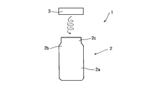
- FIG. 2 is a diagram schematically showing the configuration of the reseal can 1.
- the reseal can 1 shown in the drawing is composed of a can body 2 and a cap 3, and the can body 2 is integrally formed with a cylindrical body 2a having a sealed bottom surface and above the body 2a.
- the shoulder portion 2b has a hemispherical shape or a tapered shape and a neck portion 2c formed above the shoulder portion 2b.
- the upper end portion of the neck portion 2c is formed by curling on the outer peripheral side.
- the can main body 2 is made of a metal material such as iron or stainless steel, and is configured to be induction-heated according to a current supplied to a heating coil described later.
- the thread part is formed in the outer peripheral surface of the neck part 2c,
- the cap 3 formed so that the upper end part and an outer peripheral surface were covered was provided, and the cap 3 was covered on the neck part 2c.
- a screw portion is formed on the cap 3 by roll-on molding or the like from the outer peripheral side of the cap 3.
- Drawing 1 is a mimetic diagram for explaining an example of composition of induction heating device 4 of the beverage can.
- a cylindrical can holding body 6 that holds the reseal can 1 is tilted at a predetermined angle in a box-shaped main body case 5 so as to be rotatable around a central axis A of the can holding body 6.
- a motor 7 is installed as a rotating mechanism for rotating the can holder 6 below the bottom.
- a can body holding portion 8 having an inner diameter larger than the can body outer diameter of the reseal can 1 to be held by a predetermined length is provided, and the reseal can 1 is induction-heated on the outer periphery thereof.
- a heating coil 9 is installed.
- the height (length in the direction of the central axis A) of the can body holding portion 8 is formed below the height (length in the direction of the can central axis) of the body portion 2a or the shoulder portion 2b of the applied reseal can 1. Has been. This is to make it possible to detect the temperature of the cap 3 with a radiation thermometer 10 to be described later and to make it easier to insert and remove the reseal can 1.
- maintenance part 8 has preferable 1/2 or more of the height of the whole can.
- the height can be more stably rotated by setting the height to 2/3 or more of the overall height of the can.
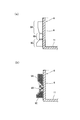
- 3A and 3B show an example of the structure of the heating coil 9 used in the present invention.
- the heating coil 9 it is preferable to use a litz wire in which a plurality of copper wires are twisted as an electric wire through which a current flows.
- the heating coil 9 can be divided into a region 9A near the opening side of the can body holding portion 8, a region 9B near the center, and a region 9C near the can locking portion 11.
- the number of windings of the electric wire the number of times the electric wire is wound around the outer periphery of the can body holding portion).
- the heating coil 9 is formed so that the winding is densely wound, the number of windings is reduced in the region 9B near the center, and the winding is coarsely wound.
- the heating coil 9 is formed by evenly winding the copper wire, the magnetic flux generated from the heating coil 9 of the opening side and the can locking portion 11 reaches the central portion, and the magnetic flux generated from the central heating coil 9 and the dry walk By doing so, since the magnetic flux density is maximized at the center, a large induced current is generated in the can body near the center of the can body holding portion 8.
- the number of windings is gradually reduced from the opening side or the can locking portion 11 side toward the center portion of the heating coil 9. If constituted in this way, since the induced current generated in the can body is homogenized, an effect of preventing excessive heat generation in the can body in the vicinity of the center portion of the heating coil 9 as described above, and problems associated therewith are prevented. In addition, the internal beverage can be heated evenly.
- the number of windings per unit length (referred to as winding density) in the direction of the can axis (center axis of the can body) is also close to the region 9A close to the opening side of the can body holding portion 8 and the can locking portion 11.
- the area 9 ⁇ / b> C is large and is configured to be small near the center of the can body holding portion 8.
- the ratio (TA / TB, TC / TB) is preferably in the range of 1.2 to 2.0. If it is smaller than 1.2, the concentration of the magnetic flux on the central portion of the heating coil 9 is not sufficiently relaxed, and an effect of preventing a malfunction due to excessive heat generation in the can near the central portion of the heating coil 9 is achieved. Is small.
- the can holder 6 is made of a material that can pass magnetic flux and has high heat resistance, such as polyacetal resin, polyetheretherketone resin, polycarbonate resin, MC nylon (registered trademark of Nippon Polypenco), etc. It is preferable.
- the reseal can 1 is inclined on the outer peripheral side of the cap 3 protruding from the can holding body 6 and the content comes into contact with the inner wall surface of the reseal can 1 by its own weight, that is, the reseal can 1 shown in FIG.
- a radiation thermometer 10 for detecting the surface temperature of the cap 3 is provided on the left side. This is to enable detection of the temperature of the cap 3 at a location where the amount of contact between the inner wall surface of the neck portion 2c and the content is large.
- a radiation thermometer 10 shown in the figure detects infrared energy such as a thermistor bolometer or a thermopile. In the above example, the radiation thermometer 10 is used.
- the surface temperature of the cap 3 can be measured, so that the surface temperature of the cap 3 is detected in a non-contact state as described above. It may be a thermometer of the type, or may be a contact type thermometer that contacts the surface of the cap 3 to detect the surface temperature of the cap 3, but the reseal can 1 is configured to rotate and heat. Therefore, it is preferable to use a non-contact type thermometer. Moreover, since the location which does not receive the influence of the temperature of the trunk
- a high frequency power supply device 12 for supplying a high frequency current to the heating coil 9 is provided below the motor 7.
- a part of the upper surface of the main body case 5 is a cover 13 that covers the opening of the can holder 6, and an operation panel (not shown) is installed on the side.
- the operation panel is provided with a start button for starting heating, a stop button for stopping the heating device halfway, a temperature adjusting button for adjusting the degree of heating, and the like.
- the reseal can 1 put into the can holder 6 has its upper portion protruding from the can holder 6 in order to facilitate the loading and unloading. It is held in the state.
- the operation panel is operated to start heating.
- a sensor (not shown) that detects the open / closed state of the cover 13 is installed, and the heating coil 9 is controlled not to be energized when the cover 13 is open.
- the can holder 6 When heating is started, the can holder 6 starts rotating around the central axis A by driving the motor 7, and a high frequency current is supplied to the heating coil 9 from the high frequency power supply device 12 controlled by the control unit 14, If the radiation thermometer 10 detects that the reseal can 1 has been heated to a predetermined temperature, it automatically stops. Since the reseal can 1 is induction-heated while rotating about its central axis A, the reseal can 1 is heated evenly. Moreover, since the effect that the contents are stirred together also occurs, uniform heating can be performed efficiently.
- the reseal can 1 is held and rotated in a state inclined by a predetermined angle with respect to the vertical line, so that the content liquid becomes a turbulent state, and the content stiffening effect is high. It is possible to heat evenly in a shorter time.
- the inclination angle with respect to the vertical line is preferably 10 ° or more and 80 ° or less, and more preferably 30 ° or more and 60 ° or less.
- the inner diameter of the can body holding portion 8 is substantially the same as the outer diameter of the can body of the body portion 2a, and the inner surface of the can body holding portion 8 is arranged so that the reseal can 1 does not roll on the inner surface of the can body holding portion 8.
- the reseal can 1 is rotated by holding the body 2a in close contact with the outer surface.
- the rotational direction of the motor 7 is abruptly changed to change the contents. Is stirred by the inertial force, and the contents reach the height at which the cap 3 is provided along the inner wall surface of the reseal can 1. This is because it is preferable that the rotational speed of 1 and the rotational direction are substantially the same.
- the inner surface of the can holder 6 is preferably covered with a heat-resistant elastic body such as rubber or sponge.
- FIG. 4 shows an example of the mode of rotation of the can holder 6 in the beverage can induction heating apparatus of the present invention.
- the rotation direction is repeatedly changed between the normal rotation direction and the reverse rotation direction.
- Control of the rotation of the can holder 6 is performed by programming a computer built in the control unit 14 in advance with an elapsed time from the start of operation and a rotation speed and a rotation direction at the elapsed time. This can be done by controlling the rotation speed of.
- in the first rotation speed increase section the rotation speed is increased to 400 rotations per minute in the first 1.5 seconds from the state where the can holder 6 into which the reseal can 1 has been put is stopped.
- the current is cut off or the rotational speed is suddenly set to 0 (zero) to rotate in the reverse direction.
- the rotation speed is increased to 400 rotations per minute in 1.5 seconds after the rotation in the reverse direction is started, and then the current is cut off or the rotation speed is suddenly set to 0 (zero) to perform normal rotation. Rotate in the direction.
- the rotation direction is repeatedly changed every 1.5 seconds, and the heating is stopped when the surface temperature of the cap 3 detected by the radiation thermometer 10 is heated to a predetermined temperature.
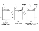
- FIG. 5 is a diagram for explaining the rotational speed of the reseal can 1 and the change in the height of the liquid level of the contents.
- FIG. (B) shows a state when reaching 400 revolutions per minute
- (c) shows a state when starting to rotate in the reverse direction after reaching 400 revolutions per minute. .
- the reseal can 1 held at a predetermined angle as shown in FIG. 1 has many contents in contact with the inner wall surface of the reseal can 1 on the side where the radiation thermometer 10 is provided. Heat is transferred from the object to the cap 3 through the neck 2c, so that the temperature of the contents and the temperature of the cap 3 become substantially the same.
- the surface temperature of the cap 3 and the temperature of the contents when the reseal can 1 is heated using the induction heating device for a beverage can having the can holding body 6 of the above-described embodiment is heated using the induction heating device for a beverage can having the can holding body 6 of the above-described embodiment. Compared.
- the reseal can 1 to be heated has a capacity of 170 g, and the reseal can 1 was filled with corn soup having a viscosity of 230 cp as the contents and heated at an output of 1350 W.
- the temperature of the corn soup before heating was 20 ° C.
- the inclination angle of the can holder 6 was set to 45 degrees, and the rotation speed was set to 400 rotations per minute for both forward rotation and reverse rotation. Then, when the surface temperature of the cap 3 reaches 55 ° C., heating and rotation are stopped, and the surface (point A) of the cap 3 of the removed reseal can 1 and the upper portion (point B) of the trunk portion 2a The temperature of the lower part (point C) of the body part 2a was measured. Next, after the reseal can 1 was shaken in the vertical direction for about 5 seconds, the temperature of the upper part of the body 2a that can be regarded as almost the same as the contents thereof was measured with the radiation thermometer 10.
- the temperature of the cap 3 and the temperature of the upper part of the trunk 2a after shaking the reseal can 1 were almost the same.
- the temperature at other measurement points was 5 to 10 ° C. higher than the temperature at the upper part of the body 2a after the cap 3 and the reseal can 1 were shaken.
- the temperature variation (standard deviation) of each measurement location was the smallest when the cap 3 was measured.
- the temperature of the cap 3 When the temperature of the cap 3 is measured as described above, it can be seen that the temperature variation at which the portion is detected is small and the difference from the temperature of the contents is small. This is presumably because the temperature of the body part is higher than the temperature of the contents because the body part 2a is induction-heated by the heating coil 9. In addition, since heat is transmitted from the can main body 2 to the cap 3 through the neck 2c, it is presumed that the influence of the heat transmitted from the body 2a is small and the temperature is not excessively increased. Furthermore, the temperature of the cap 3 and the temperature of the cap 3 are substantially the same because the heat of the stirred content contacting the inner wall surface of the neck 2c is transmitted and the temperature of the cap 3 is increased. Guessed.
- the inclination angle of the can holder 6 is set to 45 degrees, but is not particularly limited thereto, and the central axis of the reseal can 1 may be along the vertical direction.
- the rotational speed of the can holder 6 is set to 400 revolutions per minute.
- the content rises along the inner wall surface of the trunk portion 2a to the inside of the cap 3 or the inner wall surface of the neck portion 2c by centrifugal force. Therefore, the number of rotations may be 400 rotations per minute or less.
- the number of revolutions is preferably 400 revolutions per minute or more.
- the temperature measurement location is not limited to the outer peripheral surface of the cap 3 and may be configured to measure the upper end surface of the cap 3.
- the rotational speed is 600 revolutions per minute or more
- the liquid level of the contents in the can further rises, so it is preferable to measure the upper end face of the cap 3.
- the motor 7 may be installed under the bottom part of the can holding body 6 and the can holding body 6 may be rotated
- the can holding body 6 can be rotated. Since it is good, you may comprise so that a roller may be provided in the outer peripheral side of the can holding body 6, and the can holding body 6 may be rotated.
- the reseal can 1 made of iron, stainless steel, or the like is targeted, but it can also be applied to an aluminum can. In the case of an aluminum can, the amount of heat generated by induction heating is smaller than that of a steel can and the heating efficiency is inferior. Therefore, it is preferable to use appropriate means for increasing the heating capacity and the heating efficiency.
- the heating coil 9 a coil having a circumferential shape in which a litz wire is wound around the outside of the can body holding portion 8 is used.
- the shape of the coil is not limited to the circumferential shape, and the cross section is Various shapes of coils such as those having an arc-shaped cross section such as a C shape or a semicircular shape can be applied.
- the output electric power at the time of heating, rotational acceleration, and the maximum rotation speed are the shape, material, and content of the reseal can 1 Changes can be made as appropriate according to the type of object.
Landscapes
- Physics & Mathematics (AREA)
- General Physics & Mathematics (AREA)
- Electromagnetism (AREA)
- Engineering & Computer Science (AREA)
- Food Science & Technology (AREA)
- Life Sciences & Earth Sciences (AREA)
- General Induction Heating (AREA)
- Details Of Rigid Or Semi-Rigid Containers (AREA)
- Vending Machines For Individual Products (AREA)
Abstract
Description

Claims (6)
- 首部にネジ部が形成されるとともにそのネジ部にキャップが巻締められ、かつ該キャップにより再密封が可能な金属製飲料缶を保持する缶保持体を有し、その缶保持体の外周側に誘導加熱コイルが配置された飲料缶の誘導加熱装置において、
前記缶保持体は、前記キャップを前記金属製飲料缶の軸線方向の上方に突出させて、前記金属製飲料缶を挿入して保持するように構成され、
前記加熱コイルは、前記缶保持体の外周側に配置され、
前記金属製飲料缶が前記缶保持体に挿入された状態で、前記キャップの表面温度を測定する温度測定手段を備えていることを特徴とする飲料缶の誘導加熱装置。 - 前記缶保持体に保持されている前記金属製飲料缶を、該缶保持体の中心軸線を中心として回転させるように構成された回転機構を更に備えていることを特徴とする請求項1に記載の飲料缶の誘導加熱装置。
- 前記金属製飲料缶は、前記回転機構によって繰り返し回転方向を変化させられながら前記加熱コイルによって加熱されることを特徴とする請求項2に記載の飲料缶の誘導加熱装置。
- 前記回転機構は、前記金属製飲料缶の回転数が予め定めた回転数に達した後に、その飲料缶の回転方向を反転させるように構成されていることを特徴とする請求項3に記載の飲料缶の誘導加熱装置。
- 前記缶保持体は、前記金属製飲料缶の中心軸線が鉛直方向から傾斜するように形成されていることを特徴とする請求項2ないし4のいずれかに記載の飲料缶の誘導加熱装置。
- 前記温度測定手段は、前記金属製飲料缶が傾斜して回転することによって、前記金属製飲料缶の内部に充填された飲料が前記首部に接触する位置の外周側のキャップの外周面を測定するように構成されていることを特徴とする請求項5に記載の飲料缶の誘導加熱装置。
Priority Applications (6)
| Application Number | Priority Date | Filing Date | Title |
|---|---|---|---|
| US14/116,561 US9674900B2 (en) | 2011-05-10 | 2011-05-10 | Induction heating apparatus for a beverage can |
| PCT/JP2011/060772 WO2012153394A1 (ja) | 2011-05-10 | 2011-05-10 | 飲料缶の誘導加熱装置 |
| JP2013513850A JPWO2012153394A1 (ja) | 2011-05-10 | 2011-05-10 | 飲料缶の誘導加熱装置 |
| EP11865118.1A EP2709079B1 (en) | 2011-05-10 | 2011-05-10 | Inductive heating device for beverage can |
| KR1020137029770A KR20140106383A (ko) | 2011-05-10 | 2011-05-10 | 음료캔의 유도가열장치 |
| CN201180070698.9A CN103562974A (zh) | 2011-05-10 | 2011-05-10 | 饮料罐的感应加热装置 |
Applications Claiming Priority (1)
| Application Number | Priority Date | Filing Date | Title |
|---|---|---|---|
| PCT/JP2011/060772 WO2012153394A1 (ja) | 2011-05-10 | 2011-05-10 | 飲料缶の誘導加熱装置 |
Publications (1)
| Publication Number | Publication Date |
|---|---|
| WO2012153394A1 true WO2012153394A1 (ja) | 2012-11-15 |
Family
ID=47138897
Family Applications (1)
| Application Number | Title | Priority Date | Filing Date |
|---|---|---|---|
| PCT/JP2011/060772 Ceased WO2012153394A1 (ja) | 2011-05-10 | 2011-05-10 | 飲料缶の誘導加熱装置 |
Country Status (6)
| Country | Link |
|---|---|
| US (1) | US9674900B2 (ja) |
| EP (1) | EP2709079B1 (ja) |
| JP (1) | JPWO2012153394A1 (ja) |
| KR (1) | KR20140106383A (ja) |
| CN (1) | CN103562974A (ja) |
| WO (1) | WO2012153394A1 (ja) |
Cited By (4)
| Publication number | Priority date | Publication date | Assignee | Title |
|---|---|---|---|---|
| WO2014143103A1 (en) | 2013-03-15 | 2014-09-18 | Silgan Containers Llc | Temperature detection system for food container induction heating system and method |
| US9883551B2 (en) | 2013-03-15 | 2018-01-30 | Silgan Containers Llc | Induction heating system for food containers and method |
| US9967924B2 (en) | 2014-02-25 | 2018-05-08 | James Heczko | Package for storing consumable product, induction heating apparatus for heating package and system including same |
| US10278410B2 (en) | 2014-04-24 | 2019-05-07 | Silgan Containers Llc | Food container induction heating system having power based microbial lethality monitoring |
Families Citing this family (6)
| Publication number | Priority date | Publication date | Assignee | Title |
|---|---|---|---|---|
| ES2891080T3 (es) * | 2013-09-18 | 2022-01-26 | Covidien Lp | Sistema de visualización laparoscópica |
| US10433372B2 (en) * | 2013-12-20 | 2019-10-01 | Toaster Labs, Inc. | Portable fluid warming device |
| FR3033974B1 (fr) * | 2015-03-16 | 2018-11-09 | Chopin Technologies | Dispositif de chauffage, systeme de test comprenant un tel dispositif et procede de mise en œuvre d'un systeme de test. |
| AU2017282707A1 (en) | 2016-06-22 | 2018-11-15 | Société des Produits Nestlé S.A. | In-line heating device |
| CN107049044A (zh) * | 2017-03-30 | 2017-08-18 | 史宏 | 一种包装饮料的电磁加热器 |
| CN111402491B (zh) * | 2020-03-21 | 2022-01-04 | 深圳市邂逅科技有限公司 | 自动贩卖机和自动微波炒菜的方法 |
Citations (5)
| Publication number | Priority date | Publication date | Assignee | Title |
|---|---|---|---|---|
| JP2000011247A (ja) | 1998-06-23 | 2000-01-14 | Fuji Electric Co Ltd | 缶飲料の誘導加熱装置 |
| JP3259808B2 (ja) | 1994-04-05 | 2002-02-25 | 富士電機株式会社 | 缶入飲食品の加熱装置 |
| US20080029505A1 (en) * | 2006-04-21 | 2008-02-07 | Rosenbloom Richard H | Food heater |
| JP4562765B2 (ja) | 2005-01-25 | 2010-10-13 | 大和製罐株式会社 | 飲料缶の誘導加熱装置及び誘導加熱方法 |
| JP2011028397A (ja) * | 2009-07-22 | 2011-02-10 | Daiwa Can Co Ltd | 缶詰加熱装置 |
Family Cites Families (7)
| Publication number | Priority date | Publication date | Assignee | Title |
|---|---|---|---|---|
| US5201797A (en) * | 1991-10-31 | 1993-04-13 | Weng Shun Te | Induction heater having cylindrical cooking receptacle |
| JP2001109943A (ja) * | 1999-10-12 | 2001-04-20 | Matsushita Refrig Co Ltd | 飲料加熱機 |
| JP3744307B2 (ja) * | 2000-03-17 | 2006-02-08 | 富士電機リテイルシステムズ株式会社 | 飲料缶の判別方法および缶飲料の誘導加熱装置 |
| GB2400305A (en) * | 2002-01-17 | 2004-10-13 | Jung Quy Doe | Apparatus for varying the temperature of a container for food or drinks |
| US20070170174A1 (en) * | 2006-01-20 | 2007-07-26 | Segiet William W | Food inductive heating device and method |
| JP2008021526A (ja) * | 2006-07-12 | 2008-01-31 | Sanden Corp | 食品加熱装置及びそれを備えた自動販売機 |
| US8140185B2 (en) * | 2008-06-09 | 2012-03-20 | The Coca-Cola Company | Virtual vendor shelf inventory management |
-
2011
- 2011-05-10 WO PCT/JP2011/060772 patent/WO2012153394A1/ja not_active Ceased
- 2011-05-10 JP JP2013513850A patent/JPWO2012153394A1/ja active Pending
- 2011-05-10 US US14/116,561 patent/US9674900B2/en not_active Expired - Fee Related
- 2011-05-10 EP EP11865118.1A patent/EP2709079B1/en not_active Not-in-force
- 2011-05-10 KR KR1020137029770A patent/KR20140106383A/ko not_active Ceased
- 2011-05-10 CN CN201180070698.9A patent/CN103562974A/zh active Pending
Patent Citations (5)
| Publication number | Priority date | Publication date | Assignee | Title |
|---|---|---|---|---|
| JP3259808B2 (ja) | 1994-04-05 | 2002-02-25 | 富士電機株式会社 | 缶入飲食品の加熱装置 |
| JP2000011247A (ja) | 1998-06-23 | 2000-01-14 | Fuji Electric Co Ltd | 缶飲料の誘導加熱装置 |
| JP4562765B2 (ja) | 2005-01-25 | 2010-10-13 | 大和製罐株式会社 | 飲料缶の誘導加熱装置及び誘導加熱方法 |
| US20080029505A1 (en) * | 2006-04-21 | 2008-02-07 | Rosenbloom Richard H | Food heater |
| JP2011028397A (ja) * | 2009-07-22 | 2011-02-10 | Daiwa Can Co Ltd | 缶詰加熱装置 |
Non-Patent Citations (1)
| Title |
|---|
| See also references of EP2709079A4 * |
Cited By (9)
| Publication number | Priority date | Publication date | Assignee | Title |
|---|---|---|---|---|
| WO2014143103A1 (en) | 2013-03-15 | 2014-09-18 | Silgan Containers Llc | Temperature detection system for food container induction heating system and method |
| US20140263287A1 (en) * | 2013-03-15 | 2014-09-18 | Silgan Containers Llc | Temperature detection system for food container induction heating system and method |
| EP2972163A4 (en) * | 2013-03-15 | 2016-11-02 | Silgan Containers Llc | TEMPERATURE DETECTION SYSTEM FOR A FOOD CONTAINER INDUCTION HEATING SYSTEM AND METHOD |
| US9883551B2 (en) | 2013-03-15 | 2018-01-30 | Silgan Containers Llc | Induction heating system for food containers and method |
| US10237924B2 (en) * | 2013-03-15 | 2019-03-19 | Silgan Containers Llc | Temperature detection system for food container induction heating system and method |
| US9967924B2 (en) | 2014-02-25 | 2018-05-08 | James Heczko | Package for storing consumable product, induction heating apparatus for heating package and system including same |
| US10327288B2 (en) | 2014-02-25 | 2019-06-18 | James Heczko | Beverage package with induction heater |
| US10904956B2 (en) | 2014-02-25 | 2021-01-26 | James Heczko | Beverage package with induction heater |
| US10278410B2 (en) | 2014-04-24 | 2019-05-07 | Silgan Containers Llc | Food container induction heating system having power based microbial lethality monitoring |
Also Published As
| Publication number | Publication date |
|---|---|
| US9674900B2 (en) | 2017-06-06 |
| EP2709079A1 (en) | 2014-03-19 |
| EP2709079A4 (en) | 2015-04-15 |
| JPWO2012153394A1 (ja) | 2014-07-28 |
| KR20140106383A (ko) | 2014-09-03 |
| EP2709079B1 (en) | 2016-08-24 |
| CN103562974A (zh) | 2014-02-05 |
| US20140197158A1 (en) | 2014-07-17 |
Similar Documents
| Publication | Publication Date | Title |
|---|---|---|
| JPWO2012153394A1 (ja) | 飲料缶の誘導加熱装置 | |
| CN106233820B (zh) | 存储消费品的包装、用于加热包装的感应加热装置和包括前者的系统 | |
| US4538630A (en) | Microwave heated hair curler | |
| JP2010104669A (ja) | 加熱調理装置 | |
| JP4562765B2 (ja) | 飲料缶の誘導加熱装置及び誘導加熱方法 | |
| JP2004267519A (ja) | 回転式電磁誘導加熱装置 | |
| WO2015164174A1 (en) | Food container induction heating system having power based microbial lethality monitoring | |
| JP2006236856A (ja) | 金属製缶の加熱装置 | |
| JP3185707B2 (ja) | 缶飲料の誘導加熱装置 | |
| JP2001109943A (ja) | 飲料加熱機 | |
| JP2001008825A (ja) | 飲料または食品の加熱装置 | |
| JP2021006182A (ja) | 炊飯器および炊飯器の加熱制御方法 | |
| JP3204854U (ja) | ヘアローラー巻き器 | |
| JP2001118139A (ja) | 飲料または食品の加熱装置及びそれを備えた飲料自動販売機 | |
| JPH08332143A (ja) | 調理器 | |
| JP2012040404A (ja) | 調理器 | |
| JP3895506B2 (ja) | 缶詰誘導加熱方法及び装置 | |
| JP2011010935A (ja) | 電気湯沸かし器 | |
| JP2001118133A (ja) | 容器入り飲料の加熱装置及びそれを備えた飲料自動販売機 | |
| JP2002150415A (ja) | 容器入り飲食品の加熱装置 | |
| JPH1118953A (ja) | 起立状態で缶を加熱する方法と加熱装置 | |
| JP2021142120A (ja) | 炊飯器 | |
| JPH06348948A (ja) | 電磁誘導式缶回転加熱装置 | |
| JP2001118131A (ja) | 容器入り飲料の加熱装置及びそれを備えた飲料自動販売機 | |
| JP2022073726A (ja) | 加熱調理器 |
Legal Events
| Date | Code | Title | Description |
|---|---|---|---|
| 121 | Ep: the epo has been informed by wipo that ep was designated in this application |
Ref document number: 11865118 Country of ref document: EP Kind code of ref document: A1 |
|
| ENP | Entry into the national phase |
Ref document number: 2013513850 Country of ref document: JP Kind code of ref document: A |
|
| REEP | Request for entry into the european phase |
Ref document number: 2011865118 Country of ref document: EP |
|
| WWE | Wipo information: entry into national phase |
Ref document number: 2011865118 Country of ref document: EP |
|
| ENP | Entry into the national phase |
Ref document number: 20137029770 Country of ref document: KR Kind code of ref document: A |
|
| NENP | Non-entry into the national phase |
Ref country code: DE |
|
| WWE | Wipo information: entry into national phase |
Ref document number: 14116561 Country of ref document: US |