WO2012153397A1 - 継手付き螺旋波付き合成樹脂管および螺旋波付き合成樹脂管の接続構造 - Google Patents
継手付き螺旋波付き合成樹脂管および螺旋波付き合成樹脂管の接続構造 Download PDFInfo
- Publication number
- WO2012153397A1 WO2012153397A1 PCT/JP2011/060783 JP2011060783W WO2012153397A1 WO 2012153397 A1 WO2012153397 A1 WO 2012153397A1 JP 2011060783 W JP2011060783 W JP 2011060783W WO 2012153397 A1 WO2012153397 A1 WO 2012153397A1
- Authority
- WO
- WIPO (PCT)
- Prior art keywords
- synthetic resin
- spiral
- spiral wave
- pipe
- tube
- Prior art date
- Legal status (The legal status is an assumption and is not a legal conclusion. Google has not performed a legal analysis and makes no representation as to the accuracy of the status listed.)
- Ceased
Links
Images






Classifications
-
- F—MECHANICAL ENGINEERING; LIGHTING; HEATING; WEAPONS; BLASTING
- F16—ENGINEERING ELEMENTS AND UNITS; GENERAL MEASURES FOR PRODUCING AND MAINTAINING EFFECTIVE FUNCTIONING OF MACHINES OR INSTALLATIONS; THERMAL INSULATION IN GENERAL
- F16L—PIPES; JOINTS OR FITTINGS FOR PIPES; SUPPORTS FOR PIPES, CABLES OR PROTECTIVE TUBING; MEANS FOR THERMAL INSULATION IN GENERAL
- F16L9/00—Rigid pipes
- F16L9/14—Compound tubes, i.e. made of materials not wholly covered by any one of the preceding groups
- F16L9/147—Compound tubes, i.e. made of materials not wholly covered by any one of the preceding groups comprising only layers of metal and plastics with or without reinforcement
-
- F—MECHANICAL ENGINEERING; LIGHTING; HEATING; WEAPONS; BLASTING
- F16—ENGINEERING ELEMENTS AND UNITS; GENERAL MEASURES FOR PRODUCING AND MAINTAINING EFFECTIVE FUNCTIONING OF MACHINES OR INSTALLATIONS; THERMAL INSULATION IN GENERAL
- F16L—PIPES; JOINTS OR FITTINGS FOR PIPES; SUPPORTS FOR PIPES, CABLES OR PROTECTIVE TUBING; MEANS FOR THERMAL INSULATION IN GENERAL
- F16L33/00—Arrangements for connecting hoses to rigid members; Rigid hose-connectors, i.e. single members engaging both hoses
-
- B—PERFORMING OPERATIONS; TRANSPORTING
- B29—WORKING OF PLASTICS; WORKING OF SUBSTANCES IN A PLASTIC STATE IN GENERAL
- B29C—SHAPING OR JOINING OF PLASTICS; SHAPING OF MATERIAL IN A PLASTIC STATE, NOT OTHERWISE PROVIDED FOR; AFTER-TREATMENT OF THE SHAPED PRODUCTS, e.g. REPAIRING
- B29C53/00—Shaping by bending, folding, twisting, straightening or flattening; Apparatus therefor
- B29C53/56—Winding and joining, e.g. winding spirally
- B29C53/58—Winding and joining, e.g. winding spirally helically
- B29C53/78—Winding and joining, e.g. winding spirally helically using profiled sheets or strips
- B29C53/785—Winding and joining, e.g. winding spirally helically using profiled sheets or strips with reinforcements
-
- F—MECHANICAL ENGINEERING; LIGHTING; HEATING; WEAPONS; BLASTING
- F16—ENGINEERING ELEMENTS AND UNITS; GENERAL MEASURES FOR PRODUCING AND MAINTAINING EFFECTIVE FUNCTIONING OF MACHINES OR INSTALLATIONS; THERMAL INSULATION IN GENERAL
- F16L—PIPES; JOINTS OR FITTINGS FOR PIPES; SUPPORTS FOR PIPES, CABLES OR PROTECTIVE TUBING; MEANS FOR THERMAL INSULATION IN GENERAL
- F16L25/00—Construction or details of pipe joints not provided for in, or of interest apart from, groups F16L13/00 - F16L23/00
- F16L25/0036—Joints for corrugated pipes
-
- F—MECHANICAL ENGINEERING; LIGHTING; HEATING; WEAPONS; BLASTING
- F16—ENGINEERING ELEMENTS AND UNITS; GENERAL MEASURES FOR PRODUCING AND MAINTAINING EFFECTIVE FUNCTIONING OF MACHINES OR INSTALLATIONS; THERMAL INSULATION IN GENERAL
- F16L—PIPES; JOINTS OR FITTINGS FOR PIPES; SUPPORTS FOR PIPES, CABLES OR PROTECTIVE TUBING; MEANS FOR THERMAL INSULATION IN GENERAL
- F16L33/00—Arrangements for connecting hoses to rigid members; Rigid hose-connectors, i.e. single members engaging both hoses
- F16L33/28—Arrangements for connecting hoses to rigid members; Rigid hose-connectors, i.e. single members engaging both hoses for hoses with one end terminating in a radial flange or collar
-
- F—MECHANICAL ENGINEERING; LIGHTING; HEATING; WEAPONS; BLASTING
- F16—ENGINEERING ELEMENTS AND UNITS; GENERAL MEASURES FOR PRODUCING AND MAINTAINING EFFECTIVE FUNCTIONING OF MACHINES OR INSTALLATIONS; THERMAL INSULATION IN GENERAL
- F16L—PIPES; JOINTS OR FITTINGS FOR PIPES; SUPPORTS FOR PIPES, CABLES OR PROTECTIVE TUBING; MEANS FOR THERMAL INSULATION IN GENERAL
- F16L47/00—Connecting arrangements or other fittings specially adapted to be made of plastics or to be used with pipes made of plastics
- F16L47/06—Connecting arrangements or other fittings specially adapted to be made of plastics or to be used with pipes made of plastics with sleeve or socket formed by or in the pipe end
- F16L47/065—Connecting arrangements or other fittings specially adapted to be made of plastics or to be used with pipes made of plastics with sleeve or socket formed by or in the pipe end with sealing rings arranged between outer surface of pipe and inner surface of sleeve or socket, the sealing rings being placed previously on the male part
-
- F—MECHANICAL ENGINEERING; LIGHTING; HEATING; WEAPONS; BLASTING
- F16—ENGINEERING ELEMENTS AND UNITS; GENERAL MEASURES FOR PRODUCING AND MAINTAINING EFFECTIVE FUNCTIONING OF MACHINES OR INSTALLATIONS; THERMAL INSULATION IN GENERAL
- F16L—PIPES; JOINTS OR FITTINGS FOR PIPES; SUPPORTS FOR PIPES, CABLES OR PROTECTIVE TUBING; MEANS FOR THERMAL INSULATION IN GENERAL
- F16L47/00—Connecting arrangements or other fittings specially adapted to be made of plastics or to be used with pipes made of plastics
- F16L47/06—Connecting arrangements or other fittings specially adapted to be made of plastics or to be used with pipes made of plastics with sleeve or socket formed by or in the pipe end
- F16L47/12—Connecting arrangements or other fittings specially adapted to be made of plastics or to be used with pipes made of plastics with sleeve or socket formed by or in the pipe end with additional locking means
-
- F—MECHANICAL ENGINEERING; LIGHTING; HEATING; WEAPONS; BLASTING
- F16—ENGINEERING ELEMENTS AND UNITS; GENERAL MEASURES FOR PRODUCING AND MAINTAINING EFFECTIVE FUNCTIONING OF MACHINES OR INSTALLATIONS; THERMAL INSULATION IN GENERAL
- F16L—PIPES; JOINTS OR FITTINGS FOR PIPES; SUPPORTS FOR PIPES, CABLES OR PROTECTIVE TUBING; MEANS FOR THERMAL INSULATION IN GENERAL
- F16L9/00—Rigid pipes
- F16L9/02—Rigid pipes of metal
- F16L9/06—Corrugated pipes
Definitions
- the present invention relates to a synthetic resin pipe with a spiral wave and a connection structure of a synthetic resin pipe with a spiral wave, the pipe wall having a spiral wave shape, for example, used as a drainage pipe under a road or a large drainage pipe for sewerage. Is.
- concrete fume pipes are generally used as drainage pipes under roads and sewerage, but in recent years they have strengths equal to or higher than those of fume pipes, and they are more durable and lighter.
- a corrugated synthetic resin pipe that is advantageous in saving labor during construction, specifically, a pipe having a reinforcing projection spirally provided on the outer peripheral side of the main body having a substantially flat inner surface is used.
- connection structure requires a pair of upper and lower halved joints, packing sheets, caulking materials, etc. to be assembled in the field according to the connection procedure, which takes a lot of time and effort, lowers work efficiency, and reduces the number of parts. Many management was troublesome. In particular, the work of moving the two pipes to a specific position on the packing sheet after placing the packing sheet on the inner surface side of the halved joint is a heavy burden on the operator. The tension of the sheet varies from person to person, causing variations in quality.
- connection structure that allows connection work to be performed more easily and quickly
- a connection flange is provided at the end of the corrugated synthetic resin pipe by welding, a packing is provided on the contact surface between the flanges, and the flanges are connected to each other.
- a connection structure that is tightened with bolts and nuts has been proposed (see, for example, Patent Document 1). According to such a connection structure, workability can be improved as compared with the conventional half joint, and a more reliable connection structure can be provided.
- this connecting flange needs to be connected with bolts and nuts, which causes a reduction in work efficiency.
- the welded part of the flange on the pipe end is not tightly sealed, water leakage will occur, and if the flange surface is deformed, it will also cause water leakage.
- High quality is required for strength, shape and dimensions, and there is a limit to cost reduction, and the presence of a strong flange and bolts and nuts to connect it unavoidably increases the weight of the connection part.
- the flange surfaces are connected via packing, there is a limit to the water resistance and pressure resistance to the outside of the part, and there is a limit to improving the working efficiency, such as even tightening of bolts and nuts is required. there were.
- this type of large synthetic resin pipe has an inner diameter of 1000 mm or more and is almost set to a long dimension of about 5 m, and handling such as unloading and unloading must be handled carefully.
- handling such as unloading and unloading must be handled carefully.
- the present invention intends to solve a simple structure with a small number of parts, sufficient water resistance and pressure resistance and a good seal without requiring a strong material and high accuracy.
- Synthetic resin pipe with spiral wave and synthetic resin pipe with spiral wave that can be reduced in weight and cost, easy to handle, and easy to connect on site. It is to provide a connection structure.
- the present invention includes a) a first form related to a synthetic resin pipe with a spiral wave with a joint, and b) a second form related to a connection structure between the synthetic resin pipes with a spiral wave with a joint.
- This invention is a synthetic resin pipe with a spiral wave with a joint provided with the receiving part for connecting the synthetic resin pipes with a spiral wave to pipe ends,
- a receiving port extending in a tubular shape from the end of the synthetic resin tube with spiral wave toward the tube axis direction is formed of a foamable resin, and is formed on at least the outer peripheral surface of the connection side end of the formed receiving port.
- the above-mentioned FRP layer in the present invention includes those composed of a plurality of layers.
- the FRP layer can be further formed on the end face of the receiving portion.
- a reinforcing material can be provided at the receiving port.
- a synthetic resin pipe component with a spiral wave having an inner diameter larger than the outer diameter of the spiral wave-equipped tube can be embedded coaxially with the synthetic resin tube with the spiral wave.
- a synthetic resin tube part with a spiral wave having an inner diameter larger than the outer diameter of the spiral wave tube with a part of the outer peripheral surface exposed, and the synthetic resin tube with a spiral wave Can be buried coaxially.
- a circular pipe component having an inner diameter larger than the outer diameter of the spiral wave-equipped tube can be embedded coaxially with the synthetic resin tube with the spiral wave.
- reinforcing fiber chips can be embedded in a dispersed state.
- a circular pipe part having an inner diameter larger than the outer diameter of the spiral wave tube is embedded coaxially with the synthetic resin tube with the spiral wave and embedded in a state where the reinforcing fiber chips are dispersed. can do.
- the reinforcing fiber can be composed of a chopped strand mat in which glass fibers are formed in a tape shape or a sheet shape, a plain weave glass cloth, or the like.
- the spiral wave can be composed of a laminate of a steel plate having a convex cross section formed in a spiral shape and a synthetic resin covering the steel plate.
- the present invention includes a synthetic resin tube with a spiral wave with a joint having the above-described configuration, and an insertion port portion to be inserted into the port portion of the synthetic resin tube with a spiral wave with a joint.
- connection structure of a synthetic resin tube with a spiral wave composed of a synthetic resin tube with a spiral wave with an insertion opening The insertion opening portion has a length substantially the same as the length of the receiving portion extending in the tube axis direction, and a synthetic resin tube with a spiral wave having a smooth outer peripheral surface that can be engaged with the receiving portion.
- a belt-shaped resin having a convex cross section that can be engaged with the spiral groove is wound around the spiral groove at the connection side end of the synthetic resin tube with spiral wave, and the smooth An outer peripheral surface can be formed.
- a foaming resin can be filled in the spiral groove at the connection side end of the synthetic resin tube with spiral wave to form the smooth outer peripheral surface.
- the FRP layer in which the reinforcing fiber is impregnated with the resin can be formed on at least the outer peripheral surface of the connection side end portion in the insertion opening.
- the FRP layer can be further formed on the end face of the insertion opening.
- the reinforcing fiber can be composed of a chopped strand mat in which glass fibers are formed in a tape shape or a sheet shape, a plain weave glass cloth, or the like.
- a circular pipe component having an inner diameter larger than the outer diameter of the spiral wave tube can be embedded in the insertion port portion coaxially with the spiral wave synthetic resin tube.
- the reinforcing fiber chip can be embedded in the insertion port portion in a dispersed state.
- a circular pipe component having an inner diameter larger than the outer diameter of the spiral corrugated tube is embedded in the insertion port portion coaxially with the synthetic resin tube with spiral waves, and reinforcing fiber chips are dispersed. Can be buried in the state.
- a sealing material that seals a gap between the insertion opening and the receiving opening can be provided in the insertion opening.
- the insertion port formed in one synthetic resin tube with spiral waves and the receiving port extended in a cylindrical shape from the end of the other synthetic resin tube with spiral waves are fitted together.
- the connection work can be easily performed, and the bolts and nuts are not required to be evenly tightened as in the case where a conventional connection flange is provided, so that the work efficiency can be improved.
- the receiving port has a structure that securely wraps the insertion port, so that sufficient water resistance and pressure resistance can be obtained without requiring a strong material and high accuracy. It has good sealing properties, and can be reduced in weight and cost and manufactured easily as compared with the conventional work of attaching the connecting flange in a watertight and accurate manner.
- an FRP layer in which a reinforcing fiber is impregnated with resin is formed on at least the outer peripheral surface of the connection side end portion in the receiving portion, in the unlikely event of unloading at a site where the ground is poor, a spiral wave Even if the attached synthetic resin tube falls, the end portion of the synthetic resin tube with a spiral wave can be protected from breakage and deformation.
- those using synthetic resin pipe parts with spiral waves or circular pipe parts as the reinforcing material can be provided with higher water resistance and pressure resistance in addition to increasing the strength of the receiving part.
- the weight can be reduced and the material cost can be reduced, and the outer wall is the pipe wall of the synthetic resin pipe with spiral wave.
- the overall appearance of the tube is increased and the appearance is improved.
- FIG. 3 is a view corresponding to FIG. 2 showing a modification of the receiving part.
- FIG. 1 equivalent view shows 2nd Embodiment of the synthetic resin tube with a spiral wave with a joint which concerns on this invention.
- FIG. 1 equivalent view which shows 2nd Embodiment of the synthetic resin tube with a spiral wave with a joint which concerns on this invention.
- FIG. 9 is a view corresponding to FIG. 2 showing a further modification of the receiving port and the insertion port.
- FIG. 9 is a view corresponding to FIG. 2 and shows another modification of the receiving port and the insertion port.
- FIG. 9 is a view corresponding to FIG. 2 showing a fourth embodiment of a synthetic resin pipe with a spiral wave with a joint according to the present invention. It is a general view which shows the synthetic resin pipe
- FIG. 9 is a view corresponding to FIG. 2 and showing another example of a pipe material that constitutes a receiving portion.
- (a) is explanatory drawing which shows the crack state of the synthetic resin pipe
- (b) is a principal part enlarged view of Fig.17 (a).
- (a) is explanatory drawing which shows the state after the drop test of the synthetic resin pipe
- the applicant of the present application has previously filed as a related application Japanese Patent Application No. 2009-53266 (unpublished) characterized by reinforcement of the entire receiving section.
- the present invention is characterized in that the outer surface of the receiving portion is protected from damage regardless of whether the entire receiving portion is reinforced or not.
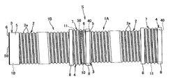
- FIG. 1 is an explanatory view showing a connection structure S of synthetic resin pipes 1A and 1B with spiral waves according to the present invention.
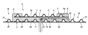
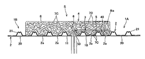
- FIGS. 1 to 4 are a first embodiment of the present invention, and FIGS. 5 and 6 are a second embodiment. 7 and 8 show a third embodiment, and FIGS. 11 to 16 show a fourth embodiment.
- reference numerals 1A, 1B, and 1C denote synthetic resin tubes with spiral waves, 2 a tube wall, 3 an insertion port, Reference numeral 4 denotes a receiving part.
- connection structure S of the synthetic resin pipe with spiral wave of the present invention comprises two synthetic resin pipes 1A and 1B with spiral wave formed by forming the pipe wall 2 into a spiral wave shape. The ends are connected to each other.
- the synthetic resin tubes with spiral waves 1A and 1B are each provided with an insertion port 3 at one end portion 10 (left end portion in the drawing) and a receiving port at the other end portion 11 (right end portion in the drawing).
- the connection structure of the present invention is not limited to such a tube connection structure having both ends, and the insertion port 3 is provided at least at the facing ends of both tubes. And the end 4 on the opposite side of each pipe may not be provided with the opening or the insertion opening.
- the pipe wall 2 of the synthetic resin pipes 1A and 1B with a spiral wave is formed in a spiral wave shape, and as shown in FIG. 2 at one end 10 (the left end in the figure) of each pipe.
- a cylindrical insertion port 3 is formed by applying a synthetic resin layer filling at least the concave portion 2a forming the wave shape on the outer surface side of the one end portion 10, and the other end portion 11 (the right end portion in the figure).
- the pipe wall 2 of each pipe has a substantially triangular shape, a substantially arc shape, or a trapezoidal crest and trough continuously forming a wave, and a trough between the crests.
- the part to include becomes the recess 2a.
- a substantially triangular shape or a substantially circular shape made of a resin molded body (for example, a coated steel plate) in which a steel material (steel plate having a convex cross section) 22 is provided on the outer peripheral side of a synthetic resin main body portion 20 whose inner surface is substantially flat.
- the arc-shaped reinforcing convex portion 21 is provided in a spiral shape, and the reinforcing convex portion 21 that forms a mountain portion with the main body portion 20 is formed by melting and extruding a partially molded body of the main body portion 20 and spirally winding it on a rotating shaft.
- the reinforcing projections 21 can be similarly spirally supplied and integrated on the partial molded body.
- a main body 20 extending from the valley on the inner peripheral side of the mountain, and the main body 20 is configured so that the inner surface of the tube has a flat shape. 20 may be omitted, and the reinforcing convex portions 21 may be connected to each other, and the inner surface side may also be a spiral corrugated surface.
- a structure in which a recessed portion 23 is provided at the peak is also a preferred embodiment.
- pressure earth pressure, etc.
- the presence of the recess 23 is a cause of fluid leakage in the conventional pipe connection structure.
- the connection structure of the present invention is employed, the pipe having such a recess 23 exists. Can be connected without causing any leakage.
- an outer surface layer 24 is further applied along the outer surface of the substantially M-shaped reinforcing convex portion 21 made of a coated steel plate.
- Synthetic resin materials used for the crests and troughs of these pipe walls 2, specifically, the main body part 20, the reinforcing convex part 21, and the outer surface layer 24, are synthetic materials such as polyolefins such as polyethylene and polypropylene, and vinyl chlorides. Resins and the like can be widely used, and other synthetic rubbers and soft resins can also be used.
- the insertion port 3 formed in the one end 10 of each of the synthetic resin pipes 1A, 1B with spiral waves fills at least the concave portion 2a forming the wave shape on the outer surface side of the one end 10.
- a synthetic resin layer 5 is applied to form a cylindrical shape whose outer surface is substantially flat along the axial direction, and can be in close contact with the inner peripheral surface of the receiving port 4 described later.
- the synthetic resin layer 5 is formed by surrounding the one end portion 10 with a mold and injecting and curing the synthetic resin material.
- the present invention is not limited to this, and the synthetic resin layer 5 is separately molded. It is possible to attach the resin layer 5 to the end portion 10 and integrate them by heat fusion or the like, or to apply the synthetic resin layer 5 by other methods.
- the one end portion 10 is pressure-deformed in the direction of diameter reduction to reduce the diameter by crushing the reinforcing convex portion 21 so that the concave portion 2a having a predetermined depth remains, and the synthetic resin layer 5 is deposited thereon.
- the insertion port 3 it is possible to configure the insertion port 3 to have a diameter smaller than that of the tube wall 2. According to this, the size of the receiving port part 4 comprised in the other end part 11 becomes smaller, and the size of the whole connection part which consists of the insertion port part 3 and the receiving port part 4 can also be made smaller.
- the synthetic resin material constituting the synthetic resin layer 5 may be either non-foamed or foamed, and olefinic resins such as polyethylene resin and polypropylene resin and other synthetic resins can be used.
- olefinic resins such as polyethylene resin and polypropylene resin and other synthetic resins
- polystyrene foam, polyethylene foam, rigid polyurethane foam, flexible polyurethane foam, rigid vinyl chloride foam, urea foam, phenol foam, acrylic foam, cellulose acetate foam, and other resins can be used.
- the synthetic resin layer 5 is deposited so that the peak portion of the end portion 10 is completely hidden. However, the peak portion may be partially exposed so that a substantially flat surface can be maintained. The synthetic resin layer 5 may be applied thickly so that the outer surface is further outward than the portion.
- the receiving port 4 is provided with a pipe material 7 having a diameter larger than that of the synthetic resin pipe 1 ⁇ / b> B with spiral waves with respect to the other end part 11 on the outer peripheral side of the other end part 11.
- the gap between the tube material 7 and the synthetic resin pipe 1B with spiral wave is filled and attached to the gap between the tube material 7 and the synthetic resin pipe 1B with a spiral wave so that the tube 7 is completely hidden.
- the peripheral surface is substantially flat along the axial direction, and functions as a receiving surface 40 into which the insertion port 3 is inserted.
- the receiving port 4 is also formed by surrounding the other end 11 and the tube material 7 with a mold and injecting and curing a synthetic resin material. It is also possible to separately form the synthetic resin layer 8 containing, and attach the synthetic resin layer 8 to the end portion 11 and integrate them by heat fusion or the like, or attach the synthetic resin layer 8 by other methods. Further, the synthetic resin material similar to that of the insertion port 3 can be used for the material of the synthetic resin layer 8.
- the tube material 7 is a tube portion in which a substantially triangular shape, a substantially arc shape, or a trapezoidal crest and trough are continuously waved like the synthetic resin tubes 1A and 1B with spiral waves. The strength is considerably increased by the presence of the pipe material 7.
- a pipe portion that forms a wave having the same structure as that of the synthetic resin pipes 1A and 1B with spiral waves is used.
- the present invention is not limited to this, and the spiral provided with the pipe wall 2 shown in FIG.
- a tube material 7 having a cross-sectional shape having a recessed portion 23 at the peak is used, or conversely, the pipe wall 2 shown in FIG. 3B is provided.
- the synthetic resin pipe 1B with a spiral wave it is possible to use a pipe material 7 that does not have a concave portion at the peak as shown in FIG. 3 (a). Further, as shown in FIG. It is good also as the comprised pipe material 7A.
- the engagement protrusion 70 engaged with the crest part of the pipe wall 2 is provided in the inner peripheral surface of the straight pipe part, and this functions as a retaining and the strength of the receiving part 4 Is configured to enhance.
- These pipe materials 7 (7A) are mainly used for maintaining the strength of the cylindrical portion protruding outward in the receiving port 4 and receiving the insertion port 3. However, the dimensions and materials can maintain the strength. It is also possible to omit the insert member such as the tube material 7 and configure the receiving portion 4 with only the synthetic resin layer 8.
- the tube material 7 (7A) and the outer peripheral surface of the tube wall 2 are firmly integrated by the synthetic resin layer 8 interposed therebetween.
- the synthetic resin layer 8 constituting the receiving portion 4 may be reinforced by embedding reinforcing materials such as reinforcing fibers and nets as necessary.
- an FRP layer 8a can be provided on the outer peripheral surface.
- the FRP layer 8a is formed by impregnating a reinforcing fiber with a synthetic resin material, and the reinforcing fiber can be formed of a woven fabric or a non-woven fabric, such as glass fiber, carbon fiber, aramid fiber, boron fiber, etc. Is mentioned.
- a chopped strand mat as a glass fiber base material for FRP formed in a tape shape or a sheet shape, and a preferred range of 100 to 300 g / m 2 per unit area can be used.
- a plain woven glass cloth or glass cloth tape for FRP a preferable density range, 16 to 25 in length, and 15 to 23 in width / 25 mm can also be used.
- the weaving method is not limited to plain weave, and may be twill weave, satin weave, tangle weave or the like.
- the said tape shape means what was cut into tape shape previously.
- the reinforcing fiber is impregnated with the synthetic resin in the foaming process of the foamed synthetic resin in the mold and cured to form the FRP layer 8a. Is done.
- the synthetic resin layer 8 when the synthetic resin layer 8 is formed of a non-foamed synthetic resin, the synthetic resin layer 8 including the tube material 7 is separately formed, and is attached to the end portion 11 and integrated by heat fusion or the like.
- the FRP layer 8a can also be formed by adhering a compression-molded FRP sheet obtained by impregnating a synthetic fiber into a reinforcing fiber in advance with an adhesive or the like on the outer peripheral surface of the receiving port formed as described above.
- a plurality of FRP sheets can be stacked to form the FRP layer 8a.
- the tensile strength in each direction is improved, and the impact resistance is stably increased.
- the FRP layer 8 a that can reinforce the outer peripheral surface of the connection side end of the receiving port 4 can also be applied to the insertion port 3.
- the FRP layer 5a having the same configuration as the FRP layer 8a can be formed on the outer peripheral surface of the connection side end portion of the insertion port portion 3, and the outer periphery of the connection side end portion of the insertion port portion 3 in this way.
- the insertion port 3 can be protected from damage as well as the receiving port 4.
- the configuration is different between the receiving port 4 and the insertion port 3, and the receiving port 4 is heavier than the insertion port 3.
- the FRP layer 8a must be formed on the connection-side outer peripheral surface of the receiving port 4 and the FRP layer 5a formed on the insertion port 3 may have an arbitrary configuration.
- the insertion port part 3 and the receiving port part 4 were each comprised in the substantially flat shape along the axial direction, this invention is not limited to such a straight shape at all,
- the insertion port part 3 Is formed in a taper shape that tapers toward the opening end, and the inner peripheral surface of the receiving port portion 4 is formed in a taper shape having substantially the same angle substantially parallel to the same, or the outer diameter or receiving port of the insertion port portion. You may make it the shape which changes so that the internal diameter of an opening
- an O-ring 6 is interposed between the insertion port 3 and the receiving port 4 as a seal member.
- an annular groove 50 into which the O-ring 6 is fitted is formed on the outer surface of the insertion opening 3, and the pipes are connected with the O-ring 6 fitted into the annular groove 50.
- the annular groove 50 in which the O-ring 6 is mounted is formed by cutting out at the distal end edge of the insertion slot 3, but at the base edge or the middle part on the opposite side of the insertion slot 3. It may be formed. Moreover, you may provide in the receptacle part 4 side.
- the shape and structure of the sealing member such as the O-ring 6 is not particularly limited as long as the space between the insertion port 3 and the receiving port 4 can be reliably sealed, and various shapes and structures of sealing members are mounted at appropriate positions. Can be done. Further, instead of mounting the O-ring 6 separately, it is also possible to integrally form an annular projection serving as a seal portion in advance.
- the synthetic resin layer 8 is applied in a state where the tube material 7 constituting the receiving portion 4 is partially exposed, and is particularly integrated with the distal end side and the tube wall 2 where strength is required.
- the base end side which is important is buried in the synthetic resin layer 8, and the other intermediate part is exposed. If the tube material 7 is exposed in this manner, weight reduction and material cost reduction can be realized, and when the tube material 7 has the same external structure as the tube wall 2 as in the present embodiment, the receiving portion 4 is concerned.
- the exposed portion has the same appearance as that of the tube wall 2, the unity of the joint portion and the entire tube is increased in appearance, and the appearance is improved. Since other configurations and modifications are basically the same as those in the first embodiment, the same reference numerals are given to the same structures, and descriptions thereof are omitted.
- reference numeral 8a denotes an FRP layer formed to reinforce the outer peripheral surface of the connection side end of the receiving port 4.
- the synthetic resin portion (synthetic resin layer 8) of the receiving portion 4 contains the reinforcing fiber 7B.
- the reinforcing fibers 7B are embedded in the form of a woven fabric, a nonwoven fabric, or a molded body solidified with a resin.
- strength improvement of the same grade is aimed at, aiming at a significant weight reduction and cost reduction.
- the concave portion 23 shown in FIG. 3B is provided at the peak portion of the reinforcing convex portion 21 of each tube.
- various corrugated synthetic resin tubes are used. Of course, it is applicable to.
- the reinforcing fiber it is preferable to use glass fiber or glass fiber.
- the receiving portion 4 is molded with a synthetic resin, a woven fabric, a nonwoven fabric or a resin molded body of the reinforcing fiber 7B is set in a molding die in advance. Can be embedded and molded.
- the molding of the receiving portion 4 is divided into two moldings of the inner portion and the outer portion, and the woven fabric of the reinforcing fiber 7B is formed on the outer surface when the molding of the first inner portion is finished. It is also possible to perform embedding molding by depositing a non-woven fabric or a resin molded body and performing a second molding thereon.
- the woven fabric, non-woven fabric, or resin molded body of the reinforcing fiber 7B may be provided so as to exist almost entirely around the inside of the receiving portion 4, or may be provided with a single or a plurality so as to exist only partially. May be. What is necessary is just to interior what was shape
- 8a is an FRP layer formed to reinforce the outer peripheral surface of the connection side end of the receptacle 4.
- FIG. 8 shows an example in which the reinforcing fiber 7B is contained in the synthetic resin layer 5 of the insertion port 3 as well as the receiving port 4, and similarly, a woven fabric, a nonwoven fabric or a resin molded body of the reinforcing fiber 7B is shown.
- Embedded molding can be performed by previously setting in a mold and molding.
- the insertion port 3 contains the reinforcing fiber 7B as in the present embodiment, and the receiving port 4 is provided with the tube material 7 of the first embodiment in place of the reinforcing fiber 7B, or any reinforcing member. Of course, it is also possible not to insert.
- the present Example demonstrated the example which provided the woven fabric, nonwoven fabric, or resin molding of the reinforcement fiber 7B in the receptacle part 4 or the insertion port part 3, as shown in FIG. 9, as shown in FIG. It is preferable that the overall strength of the synthetic resin part can be increased by adding a short cut) to the synthetic resin material to be molded and mixing with the synthetic resin material for molding the mouth portion 3 and the receiving portion 4. Furthermore, as shown in FIG. 10, it is also a preferable example to further increase the strength in combination with the woven fabric, nonwoven fabric or resin molded body of the reinforcing fiber 7B described above.
- Other configurations and modifications are basically the same as those in the first embodiment, and thus the same reference numerals are given to the same structures, and descriptions thereof are omitted.
- 9 and 10, 8a is an FRP layer formed to reinforce the outer peripheral surface of the connection side end of the receiving port 4.
- the synthetic resin tube with spiral wave 1 ⁇ / b> C is configured by forming the tube wall 2 in a spiral wave shape, and at least one end of the one end (left end in the figure).
- a cylindrical insertion port 3 is provided by attaching a synthetic resin layer 5 filling a concave portion forming a wave shape on the outer surface side, and the other end portion is provided at the other end portion 102a (right end portion in the figure).
- the receiving portion 4 made of the synthetic resin layer 8 that is attached to the outer surface side and extends in a cylindrical shape on the outer side in the axial direction
- a plurality of synthetic resin pipes 1C with spiral waves are connected to each other.
- the insertion port 3 of the synthetic resin tube 1C with spiral wave (middle right) is inserted into the receiving port 4 of the second synthetic resin tube with spiral wave (left side in the figure) and connected to each other. is there.
- the receiving portion 4 is formed by coaxially connecting the pipe material 7 having a diameter larger than that of the synthetic resin tube with spiral wave 1C on the outer surface side of the other end portion 102a.
- the synthetic resin material of the synthetic resin layer 8 is filled in at least a gap between the pipe material 7 and the synthetic resin pipe with spiral wave 1C.
- the tube wall 2 has a substantially triangular or arcuate or trapezoidal crest and trough continuously waved, and the portion including the trough between the crests is a recess.
- a substantially triangular or substantially arc-shaped reinforcing convex portion 21 made of a resin molded body (for example, a coated steel plate) in which a steel material 22 is housed is provided on the outer peripheral side of a synthetic resin main body portion 20 having a substantially flat inner surface. It is provided in a spiral shape.
- the reinforcing convex portion 21 may be formed only of the resin layer without interior of the steel material 22.
- the shape of a peak part and a trough part is not specifically limited, You may comprise in a substantially V shape, a substantially U shape, a substantially circular shape, a substantially elliptical shape, a substantially square shape, a polygonal shape, an irregular shape, and other shapes.
- the steel material 22 is also a preferred embodiment in which a concave portion 23 is provided at the top of the mountain in more detail.
- pressure earth pressure, etc.
- an outer surface layer 24 is further applied along the outer surface of the steel material 22.
- polyolefin resins such as polyethylene and polypropylene, and synthetic resins such as vinyl chloride are widely used. Other synthetic rubbers and soft resins can also be used.
- the insertion portion 3 on one end side of the synthetic resin tube with spiral waves has the synthetic resin layer 5 so as to fill at least the concave portion forming the wave shape on the outer surface side of the one end portion.
- the outer surface is formed into a substantially flat cylindrical shape along the axial direction, and is in close contact with the inner peripheral surface of the receiving portion 4 at the other end.
- the synthetic resin layer 5 constituting the insertion port 3 is formed by surrounding the one end portion with a molding die and injecting and curing a synthetic resin material. It is also possible to deposit layer 5.
- the synthetic resin material constituting the synthetic resin layer 5 may be either non-foamed or foamed, and olefinic resins such as polyethylene resin and polypropylene resin and other synthetic resins can be used.
- olefinic resins such as polyethylene resin and polypropylene resin and other synthetic resins
- polystyrene foam, polyethylene foam, rigid polyurethane foam, flexible polyurethane foam, rigid vinyl chloride foam, urea foam, phenol foam, acrylic foam, cellulose acetate foam, and other resins can be used.
- the receiving end 4 on the other end side is formed by coaxially connecting a pipe material 7 having a diameter larger than that of the synthetic resin pipe with spiral wave 1C from the outer surface side of the other end 102a.
- the inner peripheral surface of the portion is substantially flat along the axial direction, and functions as a receiving surface 40 into which the insertion port 3 is inserted.
- the synthetic resin layer material similar to that of the insertion port 3 can also be used for the synthetic resin layer 8 of the receiving port 4.
- the insertion opening 3 and the receiving opening 4 are each formed in a substantially flat shape along the axial direction.
- the present invention is not limited to such a straight shape, and the insertion opening 3 is opened.
- the taper is tapered toward the end, and the inner peripheral surface of the receiving port 4 is configured to have a taper shape of substantially the same angle substantially parallel to the tapered portion, or the outer diameter of the insertion port or the receiving port.
- the inner diameter may be changed so as to draw a curve along the axial direction.
- the receiving surface 40 of the receiving port 4 in a reverse taper shape that is reduced in diameter from the inner side toward the outer opening, thereby achieving water tightness and tightness of the O-ring 6 of the insertion port 3. .
- a stepped taper portion 42 is provided at the opening of the receiving portion 4 so that the O-ring 6 is caught by the opening when the insertion portion 3 is inserted and is not dropped off.
- the pipe material 7 housed in the receiving part 4 is a pipe part in which a substantially triangular shape, a substantially arc shape, or a trapezoidal peak and trough continuously wave.
- the strength of the receiving port 4 is considerably increased by the presence of the pipe material 7.
- the pipe wall 71 is formed in a spiral wave shape, and a pipe material (however, there is no main body part 20 on the inner peripheral side) that forms a wave having the same structure as the synthetic resin pipe with spiral wave 1C is used.
- a pipe material (however, there is no main body part 20 on the inner peripheral side) that forms a wave having the same structure as the synthetic resin pipe with spiral wave 1C is used.
- a structure in which a main body portion 20a is provided on the inner peripheral side is also a preferable example.
- the tube material 7 and the outer peripheral surface of the tube wall 2 are firmly integrated by the synthetic resin layer 8 interposed therebetween.
- the tube material 7 is covered with a synthetic resin layer 8 in a partially exposed state.
- the proximal end side which is important in terms of integration with the distal end side where the strength is required, and the tube wall 2 is buried with the synthetic resin layer 8, and other intermediate portions are exposed. If the tube material 7 is exposed in this manner, weight reduction and material cost reduction can be realized, and when the tube material 7 has the same external structure as the tube wall 2 as in the present embodiment, the receiving portion 4 is concerned.
- the exposed portion has the same appearance as that of the tube wall 2, the unity of the joint portion and the entire tube is increased in appearance, and the appearance is improved.
- an O-ring 6 is interposed between the insertion port 3 and the receiving port 4 as a seal member.
- an annular groove 50 into which the O-ring 6 is fitted is formed on the outer surface of the insertion port portion 3, and the tubes are connected with the O-ring 6 fitted into the annular groove 50.
- the annular groove 50 in which the O-ring 6 is mounted is notched at the distal end edge of the insertion slot 3, but is formed at the base edge or the middle part on the opposite side of the insertion slot 3. May be. Moreover, you may provide in the receptacle part 4 side.
- the shape and structure of the sealing member such as the O-ring 6 is not particularly limited as long as the space between the insertion port 3 and the receiving port 4 can be reliably sealed, and various shapes and structures of sealing members are mounted at appropriate positions. Can be done. Further, instead of mounting the O-ring 6 separately, it is also possible to integrally form an annular projection serving as a seal portion in advance.
- a coating agent that can improve waterproofness, weather resistance, and chemical resistance may be coated on the outer surface of the synthetic resin tube with spiral wave 1 ⁇ / b> C including the insertion port 3 and the receiving port 4 at both ends.
- the FRP layer 5a can be provided at the connection side end portion on the outer peripheral surface as in the first embodiment.
- the FRP layer is formed on the connection side end on the outer peripheral surface of the receiving port and the connection side end on the outer peripheral surface of the insertion port.
- the FRP layer can also be formed across part or all of the connection side end face of the insertion opening.
- the FRP layer is formed so as to extend from the outer peripheral surface to the end surface in this way, the outer peripheral corner portion on the receiving end connection side is more reliably reinforced.
- the manufacturing procedure of the synthetic resin tube with spiral wave 1 ⁇ / b> C includes the step S ⁇ b> 1 of forming the tube wall 2 of the synthetic resin tube with spiral wave 1 ⁇ / b> C, and the composite with spiral wave formed continuously.
- a step S2 of coaxially forming a pipe material 7 having a diameter larger than that of the synthetic resin pipe with a spiral wave at the other end 102a of the resin pipe 1C, and axially inner and outer ends of the molded pipe material 7 are respectively provided.
- step S4 of injecting is the step S4 of injecting.
- the same method as the conventional method for forming a synthetic resin tube with a spiral wave can be used. As shown in FIG. After being deformed into an M-shape in cross-sectional view, this is sent out in a spiral shape, and the outer winding tape (outer surface layer 24) is continuously fed out from the base 81 in the same spiral shape on the outer surface side, and is attached, The inner wall tape (main body portion 20) is also continuously spirally fed out from the base 82 and attached to the inner surface side, and the tube wall 2 is formed by joining and integrating in the axial direction.
- the tube material 7 is not formed at the end portion after the one-end tube wall 2 is completed, but the tube material 7 of the step S2 is formed on the formed tube wall 2 continuously with the step S1.
- the receiving part 4 is efficiently formed.
- the tube material 7 to be formed in the step S2 is transformed into the M-shaped cross-sectional view of the steel material 22 continuously supplied by the processing roller 93 in the same manner as the formation of the tube wall 2 and then sent out in a spiral shape.
- Outer winding tape (outer surface layer 24) is continuously fed out in a spiral form from the base 83 and attached to the outer surface side, the inner winding tape is omitted, and the tube material 7 is formed by joining and integrating in the axial direction. .
- the molded tube material 7 is supported from the outside in the radial direction by a plurality of guide rollers 91 as guide portions, and is supported coaxially with the tube wall 2.
- step S3 the outside of the tube wall 2 is surrounded by a cylindrical outer frame (divided in two).
- a reinforcing fiber is attached in an annular shape to the inner wall (corresponding to one end of the tube wall 2) of the outer frame of the outer frame.
- Sealing chucks 60 and 61 are attached to both ends of the tube material 7 with respect to the tube material 7 formed coaxially, and the space between the outer surface of the tube wall 2 and the inner surface of the outer frame is sealed.
- a sealed space is formed by setting the inner frame that forms the receiving surface 40 of the receiving portion 4 on the inner peripheral surface side of the tube member 7 that projects outward from the tube wall 2. .
- step S4 a synthetic resin material for forming the synthetic resin layer 8 is injected into the sealed space.
- the injection is performed through the injection port 62 communicating with the sealing chuck 60 in the axial direction.
- the injection method is not limited at all, and the sealing chuck 61 or the gold for forming the receiving surface 40 is formed.
- An inlet may be provided in the mold.
- the injected synthetic resin material When the injected synthetic resin material is foamed, it moves while filling the space, and the synthetic resin material that has reached the inner surface of the outer frame enters the reinforcing fiber attached to the inner wall of the outer frame. While impregnating, the density is increased by the foaming pressure, and an FRP layer as a skin layer is formed.
- Receptor Portion Formed in a cylindrical shape with foamed resin with a part of the outer peripheral surface of the synthetic resin pipe part with spiral wave as a reinforcing material exposed, and an FRP layer on the connection side end of the outer peripheral surface of the reception port Form and cure for 3 days.
- a defective portion D is generated at a portion that directly collides with an asphalt pavement surface or a gravel pavement surface. The end of 7 was exposed.
- E indicates the fracture surface.
- FIG. 18 (b) is an enlarged view of the scratch F. Although the line 8b forming the edge of the outer peripheral surface of the receiving port was lost over the range 8c, there was no problem in strength.
- the present invention can be used as a synthetic resin pipe applied to a drain pipe under a road, a large drain pipe for sewer, or the like.
Landscapes
- Engineering & Computer Science (AREA)
- General Engineering & Computer Science (AREA)
- Mechanical Engineering (AREA)
- Rigid Pipes And Flexible Pipes (AREA)
- Sewage (AREA)
- Joints That Cut Off Fluids, And Hose Joints (AREA)
Abstract
Description
本発明は、配管端部に螺旋波付き合成樹脂管同士を接続するための受口部が備えられている継手付き螺旋波付き合成樹脂管において、
上記螺旋波付き合成樹脂管の端部から管軸方向に向けて筒状に延びる受口部が発泡性樹脂によって成形され、その成形された上記受口部における接続側端部の少なくとも外周面に、補強繊維に樹脂を含浸させたFRP層が形成されている継手付き螺旋波付き合成樹脂管である。
b)本発明の第二の形態
本発明は、上記構成を有する継手付き螺旋波付き合成樹脂管と、この継手付き螺旋波付き合成樹脂管の上記受口部に挿入される挿し口部を備えた挿し口付き螺旋波付き合成樹脂管とから構成される螺旋波付き合成樹脂管の接続構造であって、
上記挿し口部は、管軸方向に延びる上記受口部の長さと略同じ長さからなり、上記受口部と係合し得る平滑な外周面が成されている螺旋波付き合成樹脂管の接続構造である。
螺旋波付き合成樹脂管1A,1Bの管壁2は螺旋波形状に形成されており、各管の一端部10(図中左側端部)には、図2にも示すように、少なくとも該一端部10外面側の波形状を形成している凹部2aを埋める合成樹脂層を被着することにより筒状の挿し口部3が形成され、他端部11(図中右側端部)には、該他端部11外面側に被着され且つ軸方向外側(図中右方向)に筒状に延出された合成樹脂よりなる受口部4が形成されている。
次に、図5及び6に基づき本発明の第2実施形態について説明する。
次に、図7及び8に基づき第3実施形態を説明する。
次に、図11~16に基づき第4実施形態を説明する。
次に、図14、16に基づき、螺旋波付き合成樹脂管1Cの製造方法について説明する。
本発明の継手付き螺旋波付き合成樹脂管の強度について、現場荷下ろし作業と同等の下記条件にて落下試験を行い評価した。なお、FRP層を備えていない継手付き螺旋波付き合成樹脂管についても比較例として落下試験を行い評価した。
2.砂利舗装面
(d) 落下高さ 3m(供試体の落下角度:斜め45°)
(e) サンプル数 アスファルト試験用:3個、砂利試験用:3個。
2 管壁
2a 凹部
3 挿し口部
4 受口部
5 合成樹脂層
5a FRP層
6 Oリング
7,7A 管材
7B 補強繊維
7C 補強繊維チップ
8 合成樹脂層
8a FRP層
10,11 端部
20 本体部
21 補強凸部
22 鋼材
23 凹陥部
24 外面層
40 受け面
42 段付テーパー部
50 環状溝
60,61 封止チャック
62 注入口
70 係合突起
71 管壁
81,82,83 口金
91 ガイドローラ
92,93 加工ローラ
102a 他端部
S 接続構造
Claims (20)
- 配管端部に螺旋波付き合成樹脂管同士を接続するための受口部が備えられている継手付き螺旋波付き合成樹脂管において、
上記螺旋波付き合成樹脂管の端部から管軸方向に向けて筒状に延びる受口部が発泡性樹脂によって成形され、その成形された上記受口部における接続側端部の少なくとも外周面に、補強繊維に樹脂を含浸させたFRP層が形成されていることを特徴とする継手付き螺旋波付き合成樹脂管。 - 上記受口部の端面にさらに上記FRP層が形成されている請求項1記載の継手付き螺旋波付き合成樹脂管。
- 上記受口部に補強材が設けられている請求項1記載の継手付き螺旋波付き合成樹脂管。
- 上記補強材として、上記螺旋状波付き管の外径よりも大きい内径を持つ螺旋波付き合成樹脂管部品が、上記螺旋波付き合成樹脂管と同軸に埋設されている請求項3記載の継手付き螺旋波付き合成樹脂管。
- 上記補強材として、外周面の一部を露出させた状態で上記螺旋状波付き管の外径よりも大きい内径を持つ螺旋波付き合成樹脂管部品が、上記螺旋波付き合成樹脂管と同軸に埋設されている請求項3記載の継手付き螺旋波付き合成樹脂管。
- 上記補強材として、上記螺旋状波付き管の外径よりも大きい内径を持つ円管部品が、上記螺旋波付き合成樹脂管と同軸に埋設されている請求項3記載の継手付き螺旋波付き合成樹脂管。
- 上記補強材として、補強繊維チップが分散した状態で埋設されている請求項3記載の継手付き螺旋波付き合成樹脂管。
- 上記補強材として、上記螺旋状波付き管の外径よりも大きい内径を持つ円管部品が、上記螺旋波付き合成樹脂管と同軸に埋設されるとともに、補強繊維チップが分散した状態で埋設されている請求項3記載の継手付き螺旋波付き合成樹脂管。
- 上記補強繊維が、グラスファイバーをテープ状、シート状に形成したチョップドストランドマット、平織りガラスクロス等から構成される請求項1記載の継手付き螺旋波付き合成樹脂管。
- 上記螺旋波が、螺旋状に形成された断面凸形の鋼板と、この鋼板を被覆する合成樹脂との積層体からなる請求項1記載の継手付き螺旋波付き合成樹脂管。
- 請求項1~10のいずれか1項に記載の継手付き螺旋波付き合成樹脂管と、この継手付き螺旋波付き合成樹脂管の上記受口部に挿入される挿し口部を備えた挿し口付き螺旋波付き合成樹脂管とを有する螺旋波付き合成樹脂管の接続構造であって、
上記挿し口部は、管軸方向に延びる上記受口部の長さと略同じ長さからなり、上記受口部と係合し得る平滑な外周面に形成されていることを特徴とする螺旋波付き合成樹脂管の接続構造。 - 上記挿し口部として、上記螺旋波付き合成樹脂管の接続側端部の螺旋凹溝に、螺旋凹溝と係合し得る凸状断面を有する帯状樹脂が巻き付けられ、上記平滑な外周面に形成されている請求項11記載の螺旋波付き合成樹脂管の接続構造。
- 上記挿し口部として、上記螺旋波付き合成樹脂管の接続側端部の螺旋凹溝に発泡性樹脂が充填され上記平滑な外周面に形成されている請求項11記載の螺旋波付き合成樹脂管の接続構造。
- 上記挿し口部における接続側端部の少なくとも外周面に、補強繊維に樹脂を含浸させたFRP層が形成されている請求項11記載の螺旋波付き合成樹脂管の接続構造。
- 上記挿し口部の端面にさらに上記FRP層が形成されている請求項14記載の螺旋波付き合成樹脂管の接続構造。
- 上記補強繊維が、グラスファイバーをテープ状、シート状に形成したチョップドストランドマット、平織りガラスクロス、平織りガラスクロステープ、炭素繊維、アラミド繊維、又はボロン繊維から構成される請求項14記載の螺旋波付き合成樹脂管の接続構造。
- 上記挿し口部に上記螺旋状波付き管の外径よりも大きい内径を持つ円管部品が、上記螺旋波付き合成樹脂管と同軸に埋設されている請求項11記載の螺旋波付き合成樹脂管の接続構造。
- 上記挿し口部に補強繊維チップが分散した状態で埋設されている請求項11記載の螺旋波付き合成樹脂管の接続構造。
- 上記挿し口部に上記螺旋状波付き管の外径よりも大きい内径を持つ円管部品が、上記螺旋波付き合成樹脂管と同軸に埋設されるとともに、補強繊維チップが分散した状態で埋設されている請求項11記載の螺旋波付き合成樹脂管の接続構造。
- 上記挿し口部と上記受口部との間の隙間をシールするシール材が、上記挿し口部に設けられている請求項11記載の螺旋波付き合成樹脂管の接続構造。
Priority Applications (6)
| Application Number | Priority Date | Filing Date | Title |
|---|---|---|---|
| PCT/JP2011/060783 WO2012153397A1 (ja) | 2011-05-10 | 2011-05-10 | 継手付き螺旋波付き合成樹脂管および螺旋波付き合成樹脂管の接続構造 |
| EP11865066.2A EP2708789A4 (en) | 2011-05-10 | 2011-05-10 | SCREW-SHAPED ARTIFICIAL RESIN TUBE WITH CONNECTION AND STRUCTURE FOR JOINING SCREW-SHAPED ARTIFICIAL CARTRIDGES |
| KR1020137031480A KR20140020324A (ko) | 2011-05-10 | 2011-05-10 | 조인트를 갖는 나선파형 합성 수지관 및 나선파형 합성 수지관의 접속 구조 |
| US14/116,527 US20140124081A1 (en) | 2011-05-10 | 2011-05-10 | Spirally waved synthetic resin conduit with coupling, and connection structure for spirally waved synthetic resin conduit |
| JP2013513853A JPWO2012153397A1 (ja) | 2011-05-10 | 2011-05-10 | 継手付き螺旋波付き合成樹脂管および螺旋波付き合成樹脂管の接続構造 |
| CN201180002265XA CN102893069A (zh) | 2011-05-10 | 2011-05-10 | 带接头的带螺旋波纹的合成树脂管及其连接构造 |
Applications Claiming Priority (1)
| Application Number | Priority Date | Filing Date | Title |
|---|---|---|---|
| PCT/JP2011/060783 WO2012153397A1 (ja) | 2011-05-10 | 2011-05-10 | 継手付き螺旋波付き合成樹脂管および螺旋波付き合成樹脂管の接続構造 |
Publications (1)
| Publication Number | Publication Date |
|---|---|
| WO2012153397A1 true WO2012153397A1 (ja) | 2012-11-15 |
Family
ID=47138900
Family Applications (1)
| Application Number | Title | Priority Date | Filing Date |
|---|---|---|---|
| PCT/JP2011/060783 Ceased WO2012153397A1 (ja) | 2011-05-10 | 2011-05-10 | 継手付き螺旋波付き合成樹脂管および螺旋波付き合成樹脂管の接続構造 |
Country Status (6)
| Country | Link |
|---|---|
| US (1) | US20140124081A1 (ja) |
| EP (1) | EP2708789A4 (ja) |
| JP (1) | JPWO2012153397A1 (ja) |
| KR (1) | KR20140020324A (ja) |
| CN (1) | CN102893069A (ja) |
| WO (1) | WO2012153397A1 (ja) |
Cited By (3)
| Publication number | Priority date | Publication date | Assignee | Title |
|---|---|---|---|---|
| KR101475938B1 (ko) * | 2013-05-14 | 2014-12-23 | (주)복바우 | 파형관의 연결구조 |
| KR101482204B1 (ko) * | 2014-09-04 | 2015-01-14 | 주식회사성호철관 | 걸고리식 이중벽관 |
| EP3760415A1 (de) * | 2019-07-03 | 2021-01-06 | Friess, Walter H. | Rohr |
Families Citing this family (2)
| Publication number | Priority date | Publication date | Assignee | Title |
|---|---|---|---|---|
| CN110925501A (zh) * | 2019-10-12 | 2020-03-27 | 乐昌市联丰科技有限公司 | 一种三层壁复合增强螺旋波纹管 |
| US12181086B2 (en) | 2020-06-09 | 2024-12-31 | Specialty Rtp, Inc. | End terminations and unions for a hose construction with a coupling having a non-metallic insert and method of making same |
Citations (7)
| Publication number | Priority date | Publication date | Assignee | Title |
|---|---|---|---|---|
| JPS567109B2 (ja) * | 1975-04-07 | 1981-02-16 | ||
| JPH06101396A (ja) * | 1992-09-18 | 1994-04-12 | Sekisui Chem Co Ltd | 推進工法用管継手 |
| JP2602515Y2 (ja) * | 1993-06-25 | 2000-01-17 | 金尾 茂樹 | 管継手 |
| JP2001221390A (ja) * | 1999-11-30 | 2001-08-17 | Takiron Co Ltd | コルゲート管の接続構造 |
| JP2002139178A (ja) | 2000-11-06 | 2002-05-17 | Kana Flex Corporation Kk | 大型管 |
| JP2009053266A (ja) | 2007-08-23 | 2009-03-12 | Sanyo Electric Co Ltd | 吸気構造及びそれを用いた投写型映像表示装置並びに電子機器 |
| JP2010139062A (ja) * | 2008-03-07 | 2010-06-24 | Kanaflex Corporation | 波形合成樹脂管の接続構造、及び該接続構造に用いる波形合成樹脂管、並びにその製造方法 |
Family Cites Families (13)
| Publication number | Priority date | Publication date | Assignee | Title |
|---|---|---|---|---|
| US4415389A (en) * | 1980-05-05 | 1983-11-15 | Dayco Corporation | Method of making a hose construction |
| US4763932A (en) * | 1987-07-27 | 1988-08-16 | Matz Edward I | Hose coupling |
| US4903996A (en) * | 1987-09-14 | 1990-02-27 | Man-O-War, Inc. | Fastener system for pipe coupling bands |
| JP2958376B2 (ja) * | 1990-07-26 | 1999-10-06 | 金尾 茂樹 | 継手付き波形管と波形管への継手一体形成方法 |
| US6318410B1 (en) * | 1992-05-29 | 2001-11-20 | Tokai Rubber Industries, Ltd. | Connecting structure |
| JPH07127780A (ja) * | 1993-11-02 | 1995-05-16 | Shiro Kanao | コルゲート螺旋管用継手と継手付きコルゲート螺旋管及びその製造方法並びに継手付きコルゲート螺旋管への螺旋管の接続方法 |
| US5678610A (en) * | 1995-02-24 | 1997-10-21 | Oem/Miller Corporation | Composite tube and method of manufacture |
| US5984375A (en) * | 1997-07-23 | 1999-11-16 | Schlumberger Industries, Inc. | Hose collar and method of use therefor |
| US7083204B1 (en) * | 2003-03-21 | 2006-08-01 | Pacific Roller Die Company, Inc. | Composite metal pipe coupling and assembly |
| KR20090010011A (ko) * | 2007-07-21 | 2009-01-28 | 가나플렉스 코포레이션 가부시키가이샤 | 금속수지 복합관의 접속구조 및 상기 접속구조에사용되는 금속수지 복합관 |
| CN201145115Y (zh) * | 2007-09-25 | 2008-11-05 | 河北宝硕管材有限公司 | 一种用于pvc管道的中大口径异径三通管件 |
| CN103140708B (zh) * | 2010-10-01 | 2015-02-18 | 嘉纳福株式会社 | 带连接件的合成树脂管及其连接结构 |
| CN102859246B (zh) * | 2011-04-21 | 2014-11-19 | 嘉纳福株式会社 | 合成树脂管 |
-
2011
- 2011-05-10 US US14/116,527 patent/US20140124081A1/en not_active Abandoned
- 2011-05-10 CN CN201180002265XA patent/CN102893069A/zh active Pending
- 2011-05-10 EP EP11865066.2A patent/EP2708789A4/en not_active Withdrawn
- 2011-05-10 KR KR1020137031480A patent/KR20140020324A/ko not_active Withdrawn
- 2011-05-10 JP JP2013513853A patent/JPWO2012153397A1/ja active Pending
- 2011-05-10 WO PCT/JP2011/060783 patent/WO2012153397A1/ja not_active Ceased
Patent Citations (7)
| Publication number | Priority date | Publication date | Assignee | Title |
|---|---|---|---|---|
| JPS567109B2 (ja) * | 1975-04-07 | 1981-02-16 | ||
| JPH06101396A (ja) * | 1992-09-18 | 1994-04-12 | Sekisui Chem Co Ltd | 推進工法用管継手 |
| JP2602515Y2 (ja) * | 1993-06-25 | 2000-01-17 | 金尾 茂樹 | 管継手 |
| JP2001221390A (ja) * | 1999-11-30 | 2001-08-17 | Takiron Co Ltd | コルゲート管の接続構造 |
| JP2002139178A (ja) | 2000-11-06 | 2002-05-17 | Kana Flex Corporation Kk | 大型管 |
| JP2009053266A (ja) | 2007-08-23 | 2009-03-12 | Sanyo Electric Co Ltd | 吸気構造及びそれを用いた投写型映像表示装置並びに電子機器 |
| JP2010139062A (ja) * | 2008-03-07 | 2010-06-24 | Kanaflex Corporation | 波形合成樹脂管の接続構造、及び該接続構造に用いる波形合成樹脂管、並びにその製造方法 |
Non-Patent Citations (1)
| Title |
|---|
| See also references of EP2708789A4 |
Cited By (3)
| Publication number | Priority date | Publication date | Assignee | Title |
|---|---|---|---|---|
| KR101475938B1 (ko) * | 2013-05-14 | 2014-12-23 | (주)복바우 | 파형관의 연결구조 |
| KR101482204B1 (ko) * | 2014-09-04 | 2015-01-14 | 주식회사성호철관 | 걸고리식 이중벽관 |
| EP3760415A1 (de) * | 2019-07-03 | 2021-01-06 | Friess, Walter H. | Rohr |
Also Published As
| Publication number | Publication date |
|---|---|
| US20140124081A1 (en) | 2014-05-08 |
| KR20140020324A (ko) | 2014-02-18 |
| EP2708789A1 (en) | 2014-03-19 |
| CN102893069A (zh) | 2013-01-23 |
| JPWO2012153397A1 (ja) | 2014-07-28 |
| EP2708789A4 (en) | 2014-11-26 |
Similar Documents
| Publication | Publication Date | Title |
|---|---|---|
| JP5162499B2 (ja) | 波形合成樹脂管の接続構造および該接続構造に用いる波形合成樹脂管 | |
| US7407197B2 (en) | Pipe joint infill and protective sleeve | |
| WO2012153397A1 (ja) | 継手付き螺旋波付き合成樹脂管および螺旋波付き合成樹脂管の接続構造 | |
| JP5202768B2 (ja) | 継手付き合成樹脂管およびその接続構造 | |
| JP6399695B2 (ja) | トンネルの剥落防止工法 | |
| JP5474505B2 (ja) | 受口部付き螺旋波付き合成樹脂管、挿し口部付き螺旋波付き合成樹脂管および螺旋波付き合成樹脂管の接続構造 | |
| WO2012144052A1 (ja) | 合成樹脂管 | |
| WO2013021435A1 (ja) | 螺旋波付き合成樹脂管 | |
| US6820762B2 (en) | High strength rib for storage tanks | |
| JP7002140B2 (ja) | 吊足場 | |
| CN2882985Y (zh) | 金属增强塑料带材及由其制造的金属增强塑料排水管 | |
| KR100932022B1 (ko) | 내, 외경 보강용 복층벽 하수관의 제조장치 | |
| JP2008088715A (ja) | コンクリート構造物の再構築方法、コンクリート構造物の製造方法、及び、これらの工法に用いることができる防食部材 | |
| HK1181103A (en) | Helically corrugated synthetic resin pipe with joint, and structure for connecting helically corrugated synthetic resin pipes | |
| KR200265512Y1 (ko) | 보강제를 포함하는 고강도 하수관 | |
| JP7572982B2 (ja) | Pc鋼材保護シース | |
| KR200413372Y1 (ko) | 대용량 복합저장탱크 및 이를 제조하는 방법 | |
| KR100658665B1 (ko) | 대용량 복합저장탱크 및 이를 제조하는 방법 | |
| HK1137798B (en) | Connection structure of waveform synthetic resin pipes, waveform synthetic resin pipes used for the connection structure, and manufacture method thereof | |
| HK1100691A1 (zh) | 合成树脂管 | |
| HK1100691B (en) | A synthetic resin tube | |
| JP2011247005A (ja) | 軟弱地盤の表層処理材 |
Legal Events
| Date | Code | Title | Description |
|---|---|---|---|
| WWE | Wipo information: entry into national phase |
Ref document number: 201180002265.X Country of ref document: CN |
|
| 121 | Ep: the epo has been informed by wipo that ep was designated in this application |
Ref document number: 11865066 Country of ref document: EP Kind code of ref document: A1 |
|
| ENP | Entry into the national phase |
Ref document number: 2013513853 Country of ref document: JP Kind code of ref document: A |
|
| REEP | Request for entry into the european phase |
Ref document number: 2011865066 Country of ref document: EP |
|
| WWE | Wipo information: entry into national phase |
Ref document number: 14116527 Country of ref document: US Ref document number: 2011865066 Country of ref document: EP |
|
| NENP | Non-entry into the national phase |
Ref country code: DE |
|
| ENP | Entry into the national phase |
Ref document number: 20137031480 Country of ref document: KR Kind code of ref document: A |