WO2012153425A1 - Structure de véhicule - Google Patents
Structure de véhicule Download PDFInfo
- Publication number
- WO2012153425A1 WO2012153425A1 PCT/JP2011/060989 JP2011060989W WO2012153425A1 WO 2012153425 A1 WO2012153425 A1 WO 2012153425A1 JP 2011060989 W JP2011060989 W JP 2011060989W WO 2012153425 A1 WO2012153425 A1 WO 2012153425A1
- Authority
- WO
- WIPO (PCT)
- Prior art keywords
- rocker
- vehicle body
- vehicle
- pillar
- reinforcement
- Prior art date
- Legal status (The legal status is an assumption and is not a legal conclusion. Google has not performed a legal analysis and makes no representation as to the accuracy of the status listed.)
- Ceased
Links
Images


Classifications
-
- B—PERFORMING OPERATIONS; TRANSPORTING
- B62—LAND VEHICLES FOR TRAVELLING OTHERWISE THAN ON RAILS
- B62D—MOTOR VEHICLES; TRAILERS
- B62D25/00—Superstructure or monocoque structure sub-units; Parts or details thereof not otherwise provided for
- B62D25/04—Door pillars ; windshield pillars
-
- B—PERFORMING OPERATIONS; TRANSPORTING
- B62—LAND VEHICLES FOR TRAVELLING OTHERWISE THAN ON RAILS
- B62D—MOTOR VEHICLES; TRAILERS
- B62D21/00—Understructures, i.e. chassis frame on which a vehicle body may be mounted
- B62D21/15—Understructures, i.e. chassis frame on which a vehicle body may be mounted having impact absorbing means, e.g. a frame designed to permanently or temporarily change shape or dimension upon impact with another body
-
- B—PERFORMING OPERATIONS; TRANSPORTING
- B62—LAND VEHICLES FOR TRAVELLING OTHERWISE THAN ON RAILS
- B62D—MOTOR VEHICLES; TRAILERS
- B62D25/00—Superstructure or monocoque structure sub-units; Parts or details thereof not otherwise provided for
- B62D25/02—Side panels
- B62D25/025—Side sills thereof
-
- B—PERFORMING OPERATIONS; TRANSPORTING
- B62—LAND VEHICLES FOR TRAVELLING OTHERWISE THAN ON RAILS
- B62D—MOTOR VEHICLES; TRAILERS
- B62D21/00—Understructures, i.e. chassis frame on which a vehicle body may be mounted
- B62D21/15—Understructures, i.e. chassis frame on which a vehicle body may be mounted having impact absorbing means, e.g. a frame designed to permanently or temporarily change shape or dimension upon impact with another body
- B62D21/157—Understructures, i.e. chassis frame on which a vehicle body may be mounted having impact absorbing means, e.g. a frame designed to permanently or temporarily change shape or dimension upon impact with another body for side impacts
Definitions
- the present invention relates to a vehicle structure.
- Patent Document 1 discloses a lower body structure of an automobile having a rocker extending in the front-rear direction on both lower sides of the vehicle body and a front pillar standing on the upper surface of the front end of the rocker. Is disclosed.
- the lower body structure of the automobile has a reinforcing member disposed at a connecting portion between the front pillar and the rocker, and the rear end of the rocker joint surface of the reinforcing member joined to the upper surface of the rocker is from the front in the vehicle width direction. Inclined outward in the vehicle width direction.
- the lower body structure of the automobile is configured to distribute the bending force acting on the rocker in the front-rear direction of the rocker.
- This invention is made
- a vehicle structural body according to the present invention is provided at a lower portion of a side portion of a vehicle body along a vehicle body front-rear direction and is disposed adjacent to the vehicle body front-rear direction.
- the rocker is configured to include an overlapping joint portion in which the adjacent rocker reinforcing members are overlapped and joined in the vehicle body width direction of the vehicle.
- the pillar inner portion that extends along the vehicle body vertical direction on the vehicle body side portion of the vehicle, is joined to the end portion of the rocker in the vehicle body front-rear direction, and is opposed to the vehicle body width direction.
- An end pillar configured to include a member and a pillar outer member, and an interval along the vehicle body front-rear direction between the end pillar-side end of the overlap joint and the end of the pillar inner member on the overlap joint May be set to a dimension that suppresses the occurrence of buckling wavelength antinodes when a load is applied to the rocker from the front-rear direction of the vehicle body.
- the pillar inner portion that extends along the vehicle body vertical direction on the vehicle body side portion of the vehicle is joined to the end portion of the rocker in the vehicle body front-rear direction, and is opposed to the vehicle body width direction.
- An end pillar configured to include a member and a pillar outer member, and an interval along the vehicle body front-rear direction between the end pillar-side end of the overlap joint and the end of the pillar inner member on the overlap joint Can be set to 1 ⁇ 4 or less of the buckling wavelength of the rocker when a load is applied to the rocker from the longitudinal direction of the vehicle body.
- the pillar inner portion that extends along the vehicle body vertical direction on the vehicle body side portion of the vehicle, is joined to the end portion of the rocker in the vehicle body front-rear direction, and is opposed to the vehicle body width direction.
- An end pillar including a member and a pillar outer member is provided, and the pillar inner member has a concave reinforcing portion along the vehicle body front-rear direction on the upper surface flange portion of the end portion on the overlap joint portion side. be able to.
- an end pillar extending along a vehicle body vertical direction on the vehicle body side portion of the vehicle and joined to an end portion of the rocker in the vehicle body front-rear direction, and a vehicle body side portion of the vehicle
- An intermediate pillar that extends along the vertical direction of the vehicle body and is joined to an intermediate portion of the rocker, the rocker as the rocker reinforcing member, a side reinforcing member provided at an end of the rocker, A center reinforcing member provided at an intermediate portion of the rocker, and the center reinforcing member is located outside the vehicle compartment of the vehicle at the overlapping joint portion between the side reinforcing member and the center reinforcing member.
- the vehicle structure according to the present invention has an effect that the strength can be increased.
- FIG. 1 is a partial perspective view of a vehicle body side portion of a vehicle to which the vehicle structural body according to the embodiment is applied as viewed from the outside of the passenger compartment.
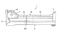
- FIG. 2 is a partial front view of the vehicle structure as viewed from the outside of the passenger compartment.
- FIG. 3 is a partial front view of the vehicle structure as viewed from the outside of the passenger compartment.
- FIG. 4 is a schematic diagram illustrating an example of an operation at the time of a frontal collision of the vehicle structure.
- FIG. 5 is a partial front view of a vehicle structure according to another embodiment as viewed from the outside of the passenger compartment.
- FIG. 6 is a schematic diagram illustrating an example of an operation at the time of a side collision of the vehicle structure.
- FIG. 1 is a partial perspective view of a vehicle body side portion to which a vehicle structural body according to an embodiment is applied as seen from the outside of the passenger compartment.
- FIGS. 2 and 3 show the vehicle structural body as seen from the outside of the passenger compartment.
- FIG. 4 is a partial front view
- FIG. 4 is a schematic diagram illustrating an example of an operation at the time of a frontal collision of the vehicle structure
- FIG. 5 is a part of the vehicle structure according to another embodiment as viewed from the outside of the passenger compartment.
- FIG. 6 is a schematic diagram for explaining an example of an operation at the time of a side collision of the vehicle structure.
- the direction along the traveling direction of the vehicle 2 is the vehicle longitudinal direction
- the height direction of the vehicle 2 is the vehicle vertical direction, the vehicle vertical direction, and the direction orthogonal to the vehicle vertical direction.
- the vehicle body width direction is typically, in a state where the wheels of the vehicle 2 are installed on a flat road surface, the vehicle body vertical direction is a direction along the vertical direction, and the vehicle body longitudinal direction and the vehicle body width direction are directions along the horizontal direction.
- the space side inside the vehicle 2 in which the passenger compartment of the vehicle 2 is partitioned is referred to as the vehicle interior side
- the space outside the vehicle 2 on the outside air side is referred to as the vehicle exterior side.
- the arrow FR shown in FIG. 1 indicates the front side in the longitudinal direction of the vehicle body
- the arrow UP indicates the upper side in the vertical direction of the vehicle body.
- the vehicle structure 1 of the present embodiment is applied to a vehicle body 3 of a vehicle 2 as shown in FIG.
- the vehicle 2 includes a vehicle structure 1 as a high-strength, high-rigidity vehicle body skeleton component that forms the skeleton of the vehicle body 3.
- the vehicle structure 1 includes a front pillar (A pillar) 4, a center pillar (B pillar) 5, a rear pillar (C pillar) 6, a roof side rail 7, a rocker (side sill) 8, and the like.
- the front pillar 4, center pillar 5, rear pillar 6, roof side rail 7, and rocker 8 are provided in pairs on both sides in the vehicle body width direction, but in the following, one side will be described unless otherwise specified, and the other side will be described. Is omitted.
- the front pillar 4, the center pillar 5, and the rear pillar 6 are pillar-shaped members, and are extended on the side of the vehicle body along the vertical direction of the vehicle body, that is, the vertical direction.
- the front pillar 4 is an end pillar, which is a front portion of the vehicle body in the longitudinal direction of the vehicle body
- the center pillar 5 is an intermediate pillar, which is an intermediate portion of the vehicle body in the longitudinal direction of the vehicle body
- the rear pillar 6 is an end portion. It is a pillar and is respectively arranged at the rear part of the vehicle body in the longitudinal direction of the vehicle body.
- the roof side rail 7 and the rocker 8 are beam-shaped members, and are provided on the side of the vehicle body along the vehicle body front-rear direction, that is, the horizontal direction.
- the roof side rail 7 is arranged at the upper part of the vehicle body in the vertical direction of the vehicle body
- the rocker 8 is arranged at the lower part of the vehicle body in the vertical direction of the vehicle body.
- the vehicle structural body 1 forms a skeleton of the vehicle body 3 by connecting the front pillar 4, the center pillar 5, the rear pillar 6, the roof side rail 7, and the rocker 8. That is, the front pillar 4 has an upper end joined to one end of the roof side rail 7 in the vehicle front-rear direction, here a front end and a lower end joined to the front end of the rocker 8 in the vehicle front-rear direction.
- the center pillar 5 has an upper end portion joined to an intermediate portion of the roof side rail 7 in the longitudinal direction of the vehicle body and a lower end portion joined to an intermediate portion of the rocker 8 in the longitudinal direction of the vehicle body.
- the rear pillar 6 has an upper end joined to the other end of the roof side rail 7 in the vehicle longitudinal direction, here a rear end and a lower end joined to the rear end of the rocker 8 in the vehicle longitudinal direction.
- the vehicle structure 1 typically includes a rocker 8 as a side sill that generates an important drag at the time of a frontal collision or a side collision with the vehicle body 3.
- a rocker 8 as a side sill that generates an important drag at the time of a frontal collision or a side collision with the vehicle body 3.
- the strength is enhanced by joining adjacent rocker reinforcing members in a predetermined manner.
- the vehicle structural body 1 has a form in which adjacent rocker reinforcing members are joined together and so-called buckling wavelength is considered.
- the front pillar 4, the center pillar 5, the rear pillar 6, the roof side rail 7, and the rocker 8 are each configured to include an outer member, an inner member, various reinforcing members, and the like as structural members.
- the front pillar 4 includes a front pillar inner panel (hereinafter, abbreviated as “pillar inner” unless otherwise specified) 41 as a pillar inner member, and a front pillar outer panel (hereinafter referred to as “pillar outer” as a pillar outer member).
- pillar inner front pillar inner panel
- pillar outer front pillar outer panel
- pillar reinforcement front pillar outer reinforcement
- the front pillar 4 has a substantially U-shaped cross-sectional shape, and a pillar inner 41 and a pillar outer 91 that are opposed to each other in the vehicle body width direction are joined to form a main structural member.
- the pillar inner 41 is disposed facing the vehicle interior side and constitutes the vehicle body width direction inner side portion of the front pillar 4
- the pillar outer 91 is disposed facing the vehicle interior side and constitutes the vehicle body width direction outer side portion of the front pillar 4.
- the pillar reinforcement 42 is disposed between the pillar inner 41 and the pillar outer 91 with respect to the vehicle body width direction, and reinforces the strength and rigidity of the front pillar 4 as a reinforcing member.
- the rocker 8 includes a rocker inner panel (hereinafter, abbreviated as “rocker inner” unless otherwise specified) 81 and a rocker outer panel (hereinafter abbreviated as “rocker outer”).
- Rocker outer reinforcement front as a rocker reinforcement member (hereinafter sometimes abbreviated as “Rocka reinforcement FR”) 82, Rocker outer reinforcement middle (hereinafter “Rocka reinforcement MDL”) 83 and an outer reinforcement rear (not shown, hereinafter may be abbreviated as “Rocky reinforcement RR”).
- the rocker 8 is a main structural member in which a rocker inner 81 and a rocker outer 94 which are opposed to each other in the vehicle body width direction with a substantially U-shaped cross-sectional shape are joined.
- the rocker inner 81 is disposed facing the vehicle interior side and constitutes the vehicle body width direction inner side portion of the rocker 8
- the rocker outer 94 is disposed facing the vehicle interior side and constitutes the vehicle body width direction outer side portion of the rocker 8.
- the rocker reinforcement FR82, the rocker reinforcement MDL83, and the rocker reinforcement RR (not shown) are arranged between the rocker inner 81 and the rocker outer 94 in the vehicle body width direction, and provide the strength and rigidity of the rocker 8 as a reinforcing member. Reinforce.
- the center pillar 5 and the rear pillar 6 have substantially the same configuration as the front pillar 4 and will not be described in detail.
- the roof side rail 7 is also configured to include an inner member, an outer member, a reinforcing member, etc., but detailed description thereof is omitted here.
- the vehicle structural body 1 includes a cylinder outer panel 9 as shown in FIG.
- the cylinder outer panel 9 constitutes the side surface of the vehicle body.
- the cylinder outer panel 9 includes a front pillar outer panel 91 of the front pillar 4 that extends in the vehicle vertical direction at the front portion of the vehicle side surface, and a center outer panel 92 of the center pillar 5 that extends in the vehicle vertical direction at the vehicle body longitudinal direction intermediate portion on the vehicle side surface.
- the rear pillar outer panel 93 of the rear pillar 6 that extends in the vehicle vertical direction at the rear of the vehicle side surface and the rocker outer panel 94 of the rocker 8 that extends in the vehicle front-rear direction at the lower side of the vehicle body are integrally formed. . That is, the outer outer panel 9 is disposed outside the passenger compartment such as the pillar reinforcement 42, the rocker reinforcement FR82, the rocker reinforcement MDL83, and the rocker reinforcement RR.
- the rocker reinforcement FR82, the rocker reinforcement MDL83, and the rocker reinforcement RR (not shown), which are the rocker reinforcement members of the rocker 8 of the present embodiment, are formed as rod-like members separately from each other. That is, it is divided into a plurality of members with respect to the longitudinal direction of the vehicle body.
- the rocker reinforcement FR82, the rocker reinforcement MDL83, and the rocker reinforcement RR are arranged adjacent to each other in the vehicle longitudinal direction.
- the rocker reinforcement FR82 is disposed at the front end portion of the rocker 8 in the front-rear direction of the vehicle body, and is located beside the lower end of the front pillar 4.
- the rocker reinforcement MDL 83 is disposed in the vehicle longitudinal direction intermediate portion of the rocker 8 and is located below the center pillar 5.
- a rocker reinforcement RR (not shown) is disposed at the front end portion of the rocker 8 in the front-rear direction of the vehicle body, and is located beside the lower end of the rear pillar 6. That is, the rocker 8 is a rocker reinforcement member as a rocker reinforcement member FR82 and rocker reinforcement FR82 as a side reinforcement member provided at an end portion of the rocker 8, and a rocker reinforcement member as a center reinforcement member provided at an intermediate portion of the rocker 8. It is configured to include MDL83.
- the rocker 8 includes an overlapping joint 84 in which adjacent rocker reinforcement FR82 and rocker reinforcement MDL83 are joined to each other in the vehicle body width direction of the vehicle 2.
- the overlapping joint 84 is located between the front pillar 4 and the center pillar 5 in the rocker 8 with respect to the longitudinal direction of the vehicle body.
- the rocker 8 includes an overlapping joint (not shown) in which the adjacent rocker reinforcement MDL83 and the rocker reinforcement RR are joined to each other in the vehicle body width direction of the vehicle 2.
- the overlapping joint portion between the rocker reinforcement MDL 83 and the rocker reinforcement RR is located between the center pillar 5 and the rear pillar 6 in the rocker 8 with respect to the vehicle longitudinal direction. Since the overlapping joint portion has substantially the same configuration as the overlapping joint portion 84, illustration and description thereof are omitted here.
- the end of the rocker reinforcement FR82 on the side of the center pillar 5 and the end of the rocker reinforcement MDL83 on the side of the front pillar 4 are overlapped in the vehicle body width direction, and this overlapped portion can be used in various ways such as spot welding. It is comprised by joining by the joining method of.
- the rocker 8 has an overlapping joint 84 between the rocker reinforcement FR82 and the rocker reinforcement MDL83, the end of the rocker reinforcement FR82 is located outside the vehicle interior, and the end of the rocker reinforcement MDL83 is on the vehicle interior side. To position. More specifically, in the rocker 8, the rocker reinforcement FR82 and the rocker reinforcement RR are arranged outside the vehicle compartment, while the rocker reinforcement MDL83 is arranged inside the vehicle interior.
- the rocker 8 has a predetermined distance S along the vehicle body front-rear direction between the end 83a of the overlapping joint 84 on the front pillar 4 side and the end of the front pillar 4, here the end 41a of the pillar inner 41 on the overlapping joint 84 side.
- Set to the dimensions of An end 83a on the front pillar 4 side of the overlap joint 84 corresponds to an end on the front pillar 4 side of the rocker reinforcement MDL 83, more specifically, an end on the overlap joint 84 side.
- An end 41 a of the pillar inner 41 on the overlapping joint portion 84 side corresponds to a rear end of the pillar inner 41.
- the interval S is set to a dimension that suppresses the occurrence of a buckling wavelength antinode of the rocker 8 when a load is applied to the rocker 8 from the longitudinal direction of the vehicle body.
- the buckling wavelength of the rocker 8 is a buckling wavelength when a large load acts on the rocker 8 from the longitudinal direction of the rocker 8 and the rocker 8 is buckled and deformed. Furthermore, the buckling wavelength of the rocker 8 is the occurrence of the nth buckling that occurs at intervals in the longitudinal direction when a load is applied to the rocker 8 from the longitudinal direction of the vehicle body and the rocker 8 is buckled and deformed. This corresponds to the length corresponding to the interval between the location and the n + 1th occurrence of buckling.
- the buckling wavelength of the rocker 8 is typically determined according to the cross-sectional shape of a cross section (cross section along the vehicle body width direction) intersecting the longitudinal direction of the rocker 8, and is expressed by, for example, the following mathematical formula (1). Can do.
- Equation (1) “ ⁇ ” represents the buckling wavelength of the rocker 8
- “H” represents the height of the cross section intersecting the longitudinal direction of the rocker 8
- “W” represents the width of the cross section intersecting the longitudinal direction of the rocker 8. ing.
- ⁇ (H + W) / 2 (1)
- the interval S in the present embodiment is set to a quarter or less of the buckling wavelength ⁇ of the rocker 8.
- the rocker 8 sets the space
- the pillar inner 41 of the present embodiment has a horizontal bead 41b as a concave reinforcing portion.
- an end portion (in the vicinity of the end 41a) on the overlapping joint portion 84 side of the pillar inner 41 is located between the rocker inner 81 and the rocker reinforcement FR82 with respect to the vehicle body width direction.
- the horizontal bead 41b is provided below the upper surface flange portion 41c at the end of the pillar inner 41 on the overlapping joint portion 84 side. That is, the horizontal bead 41b is provided below the upper surface flange portion 41c of the portion sandwiched between the rocker inner 81 and the rocker reinforcement FR82 in the pillar inner 41.
- the horizontal bead 41b is provided along the vehicle body front-rear direction, that is, along the horizontal direction, and is formed as a recess recessed toward the vehicle interior side.
- the pillar inner 41 is provided with the horizontal beads 41b on the upper surface flange portion 41c, so that the number of ridge lines (corner portions) along the horizontal direction is relatively increased, and the buckling strength against the load in the longitudinal direction of the vehicle body is relatively increased. be able to.
- the vehicle structure 1 configured as described above includes an overlapping joint portion 84 between the rocker reinforcement FR82 and the rocker reinforcement MDL83, and an overlapping joint portion (not shown) between the rocker reinforcement MDL83 and the rocker reinforcement RR. Since the strength is increased, for example, the strength of the rocker 8 against a side collision with the vehicle body 3 can be increased.
- the vehicle structure 1 when the front tire of the vehicle 2 is pressed and contacts the rocker 8 at the time of a frontal collision with the vehicle body 3, the vehicle structure 1 is indicated by an arrow A in FIG. 3.
- tire load input tire axial force
- the vehicle structure 1 is such that the front pillar 4 is about to fall backward in the vehicle body front-rear direction, and as shown by an arrow C in FIG.
- a compressive stress is generated on the rear side in the longitudinal direction of the vehicle here, and a flow of compressive stress is generated on the upper surface flange portion of the rocker 8.
- the vehicle structural body 1 compressive stress concentration occurs due to a shape change at the rear end portion (in the vicinity of the end 41a) of the front pillar 4.
- the horizontal bead 41 b is provided on the upper surface flange portion 41 c of the pillar inner 41, the number of ridge lines along the horizontal direction in the pillar inner 41 is relatively increased, and the ridge line increases.
- the ridge strength can be increased relatively.
- the vehicle structure 1 can increase the strength of the rear end portion of the front pillar 4 on the upper surface flange portion 41 c side and the strength of the rocker 8 on the upper surface flange portion side at the joint portion between the front pillar 4 and the rocker 8. Therefore, the deformation with respect to the frontal collision can be suppressed, and therefore the collapse of the front pillar 4 can be suppressed.
- the vehicle structure 1 when the tire load input along the longitudinal direction of the vehicle body is generated with respect to the rocker 8 as described above, the rear end portion (in the vicinity of the end 41 a) of the pillar inner 41 of the front pillar 4 and the rocker 8. A change in strength occurs between the overlapping joint portion 84, and a compressive stress concentration occurs in this strength change portion (portion corresponding to the interval S).
- the vehicular structure 1 since the distance S between the pillar inner 41 and the overlapping joint 84 is set to be equal to or less than 1 ⁇ 4 of the buckling wavelength of the rocker 8, the vehicular structure 1 has the abdomen of the buckling wavelength of the rocker 8. Is suppressed. That is, the vehicle structure 1 includes an upper end (see point D in FIG.
- the vehicle structure 1 relaxes the stress concentration at the strength changing portion between the rear end portion (in the vicinity of the end 41a) of the pillar inner 41 of the front pillar 4 and the overlapping joint portion 84 of the rocker 8, and frontal collision occurs.
- the deformation of the rocker 8 and the like can be increased.
- the rocker 8 includes a rocker reinforcement FR82, a rocker reinforcement MDL83, and the like as a rocker reinforcement member.
- the rocker 8 is adjacent to the rocker reinforcement FR82 and the rocker reinforcement MDL83 in the vehicle width direction of the vehicle 2. It is comprised including the duplication junction part 84 overlapped and joined. Therefore, the vehicle structure 1 can increase the strength of the rocker 8 against a collision with the vehicle body 3.
- the rocker 8 described above has an end portion of the rocker reinforcement MDL 83 on the vehicle exterior side at the overlapping joint portion 84 between the rocker reinforcement FR 82 and the rocker reinforcement MDL 83. It may be configured such that the end of the rocker reinforcement FR82 is located on the vehicle interior side. That is, in the rocker 8, the rocker reinforcement FR82 and the rocker reinforcement RR (not shown) may be disposed on the vehicle interior side, while the rocker reinforcement MDL83 may be disposed on the vehicle exterior side.
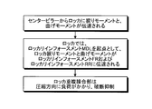
- the vehicle structure 1 transmits a torsional moment and a bending moment from the center pillar 5 to the rocker 8 at the time of a side collision with the vehicle body 3. Then, in the rocker 8, the torsional moment and the bending moment are transmitted to the rocker reinforcement FR ⁇ b> 82 and the rocker reinforcement RR in the rocker 8 from the rocker reinforcement MDL ⁇ b> 83 located below the center pillar 5. At this time, the vehicle structure 1 behaves such that the end of the rocker reinforcement MDL83 located outside the vehicle compartment at the overlapping joint 84 moves toward the vehicle interior side. A load (load) acts in the compression direction on the spot welded portion or the like of the joint portion 84.
- the vehicle structural body 1 can suppress the breakage of the rocker reinforcement FR82 and the rocker reinforcement MDL83 at the overlapping joint 84, and thus can further increase the strength of the rocker 8.
Landscapes
- Engineering & Computer Science (AREA)
- Chemical & Material Sciences (AREA)
- Combustion & Propulsion (AREA)
- Transportation (AREA)
- Mechanical Engineering (AREA)
- Body Structure For Vehicles (AREA)
Abstract
Priority Applications (3)
| Application Number | Priority Date | Filing Date | Title |
|---|---|---|---|
| PCT/JP2011/060989 WO2012153425A1 (fr) | 2011-05-12 | 2011-05-12 | Structure de véhicule |
| JP2013513870A JP5630575B2 (ja) | 2011-05-12 | 2011-05-12 | 車両用構造体 |
| EP11864976.3A EP2708449B1 (fr) | 2011-05-12 | 2011-05-12 | Structure de véhicule |
Applications Claiming Priority (1)
| Application Number | Priority Date | Filing Date | Title |
|---|---|---|---|
| PCT/JP2011/060989 WO2012153425A1 (fr) | 2011-05-12 | 2011-05-12 | Structure de véhicule |
Publications (1)
| Publication Number | Publication Date |
|---|---|
| WO2012153425A1 true WO2012153425A1 (fr) | 2012-11-15 |
Family
ID=47138923
Family Applications (1)
| Application Number | Title | Priority Date | Filing Date |
|---|---|---|---|
| PCT/JP2011/060989 Ceased WO2012153425A1 (fr) | 2011-05-12 | 2011-05-12 | Structure de véhicule |
Country Status (3)
| Country | Link |
|---|---|
| EP (1) | EP2708449B1 (fr) |
| JP (1) | JP5630575B2 (fr) |
| WO (1) | WO2012153425A1 (fr) |
Cited By (6)
| Publication number | Priority date | Publication date | Assignee | Title |
|---|---|---|---|---|
| JP2016155466A (ja) * | 2015-02-25 | 2016-09-01 | マツダ株式会社 | 自動車の側部車体構造 |
| JP2017039465A (ja) * | 2015-08-21 | 2017-02-23 | トヨタ自動車株式会社 | 車両下部構造 |
| US9738319B2 (en) | 2015-03-03 | 2017-08-22 | Toyota Jidosha Kabushiki Kaisha | Vehicle side portion structure |
| JP2017193292A (ja) * | 2016-04-22 | 2017-10-26 | 本田技研工業株式会社 | 車体前部構造 |
| US9988087B2 (en) * | 2013-03-26 | 2018-06-05 | Toyota Jidosha Kabushiki Kaisha | Vehicle body side structure of automobile |
| JP2018118697A (ja) * | 2017-01-27 | 2018-08-02 | マツダ株式会社 | 車両の側部車体構造 |
Citations (4)
| Publication number | Priority date | Publication date | Assignee | Title |
|---|---|---|---|---|
| JPS62102770U (fr) * | 1985-12-20 | 1987-06-30 | ||
| JPH11342869A (ja) | 1998-06-01 | 1999-12-14 | Toyota Motor Corp | 自動車の下部車体構造 |
| JP2000255451A (ja) * | 1999-03-10 | 2000-09-19 | Suzuki Motor Corp | 自動車の前部車体構造 |
| JP2010083255A (ja) * | 2008-09-30 | 2010-04-15 | Toyota Auto Body Co Ltd | 自動車のロッカー構造 |
Family Cites Families (2)
| Publication number | Priority date | Publication date | Assignee | Title |
|---|---|---|---|---|
| DE60017033T2 (de) * | 1999-09-02 | 2005-12-15 | Nissan Motor Co., Ltd., Yokohama | Fahrzeugstruktur für Bodenplatte |
| JP5464734B2 (ja) * | 2009-09-11 | 2014-04-09 | ダイハツ工業株式会社 | 車両の車体側部構造 |
-
2011
- 2011-05-12 JP JP2013513870A patent/JP5630575B2/ja not_active Expired - Fee Related
- 2011-05-12 WO PCT/JP2011/060989 patent/WO2012153425A1/fr not_active Ceased
- 2011-05-12 EP EP11864976.3A patent/EP2708449B1/fr not_active Not-in-force
Patent Citations (4)
| Publication number | Priority date | Publication date | Assignee | Title |
|---|---|---|---|---|
| JPS62102770U (fr) * | 1985-12-20 | 1987-06-30 | ||
| JPH11342869A (ja) | 1998-06-01 | 1999-12-14 | Toyota Motor Corp | 自動車の下部車体構造 |
| JP2000255451A (ja) * | 1999-03-10 | 2000-09-19 | Suzuki Motor Corp | 自動車の前部車体構造 |
| JP2010083255A (ja) * | 2008-09-30 | 2010-04-15 | Toyota Auto Body Co Ltd | 自動車のロッカー構造 |
Non-Patent Citations (1)
| Title |
|---|
| See also references of EP2708449A4 * |
Cited By (10)
| Publication number | Priority date | Publication date | Assignee | Title |
|---|---|---|---|---|
| US9988087B2 (en) * | 2013-03-26 | 2018-06-05 | Toyota Jidosha Kabushiki Kaisha | Vehicle body side structure of automobile |
| JP2016155466A (ja) * | 2015-02-25 | 2016-09-01 | マツダ株式会社 | 自動車の側部車体構造 |
| US9738319B2 (en) | 2015-03-03 | 2017-08-22 | Toyota Jidosha Kabushiki Kaisha | Vehicle side portion structure |
| JP2017039465A (ja) * | 2015-08-21 | 2017-02-23 | トヨタ自動車株式会社 | 車両下部構造 |
| CN106467139A (zh) * | 2015-08-21 | 2017-03-01 | 丰田自动车株式会社 | 车辆下部结构 |
| US10232885B2 (en) | 2015-08-21 | 2019-03-19 | Toyota Jidosha Kabushiki Kaisha | Vehicle lower portion structure |
| CN106467139B (zh) * | 2015-08-21 | 2021-01-15 | 丰田自动车株式会社 | 车辆下部结构 |
| JP2017193292A (ja) * | 2016-04-22 | 2017-10-26 | 本田技研工業株式会社 | 車体前部構造 |
| CN107303920A (zh) * | 2016-04-22 | 2017-10-31 | 本田技研工业株式会社 | 车身前部构造 |
| JP2018118697A (ja) * | 2017-01-27 | 2018-08-02 | マツダ株式会社 | 車両の側部車体構造 |
Also Published As
| Publication number | Publication date |
|---|---|
| EP2708449A4 (fr) | 2015-01-21 |
| JP5630575B2 (ja) | 2014-11-26 |
| EP2708449A1 (fr) | 2014-03-19 |
| JPWO2012153425A1 (ja) | 2014-07-28 |
| EP2708449B1 (fr) | 2016-08-10 |
Similar Documents
| Publication | Publication Date | Title |
|---|---|---|
| US9266568B2 (en) | Vehicle body lower section structure | |
| US9180916B2 (en) | Vehicle body lower section structure | |
| US8690227B2 (en) | Lower vehicle-body structure of vehicle | |
| JP6449562B2 (ja) | 車両用骨格構造 | |
| JP4677025B2 (ja) | 車体前部構造 | |
| JP6256518B2 (ja) | 車両の側部車体構造 | |
| JP6256519B2 (ja) | 車両の側部車体構造 | |
| JP6432535B2 (ja) | 車両の前部車体構造 | |
| WO2013018415A1 (fr) | Structure latérale de carrosserie de véhicule | |
| US20160107701A1 (en) | Vehicle body structure | |
| JP2009101815A (ja) | 車両の前部車体構造 | |
| JP5630575B2 (ja) | 車両用構造体 | |
| JP6443413B2 (ja) | 車両の後部車体構造 | |
| CN116096623A (zh) | 用于机动车的车身结构 | |
| CN107021136A (zh) | 车身前部结构 | |
| JP6256520B2 (ja) | 車両の側部車体構造 | |
| JP5686586B2 (ja) | 自動車用車体骨格における補強構造 | |
| KR20120045894A (ko) | 차량용 서브 프레임 | |
| JP6110834B2 (ja) | 車体側部構造 | |
| JP6569705B2 (ja) | 車両用骨格構造 | |
| JP6256517B2 (ja) | 車両の側部車体構造 | |
| JP5831130B2 (ja) | フロントピラー構造 | |
| WO2015076023A1 (fr) | Structure de section arrière de châssis de véhicule | |
| JP2014166781A (ja) | 車両の車体下部構造 | |
| JP5745291B2 (ja) | 自動車車体の骨格部材 |
Legal Events
| Date | Code | Title | Description |
|---|---|---|---|
| 121 | Ep: the epo has been informed by wipo that ep was designated in this application |
Ref document number: 11864976 Country of ref document: EP Kind code of ref document: A1 |
|
| ENP | Entry into the national phase |
Ref document number: 2013513870 Country of ref document: JP Kind code of ref document: A |
|
| REEP | Request for entry into the european phase |
Ref document number: 2011864976 Country of ref document: EP |
|
| WWE | Wipo information: entry into national phase |
Ref document number: 2011864976 Country of ref document: EP |
|
| NENP | Non-entry into the national phase |
Ref country code: DE |