WO2012153479A2 - Appareil d'acquisition d'informations d'objet - Google Patents
Appareil d'acquisition d'informations d'objet Download PDFInfo
- Publication number
- WO2012153479A2 WO2012153479A2 PCT/JP2012/002874 JP2012002874W WO2012153479A2 WO 2012153479 A2 WO2012153479 A2 WO 2012153479A2 JP 2012002874 W JP2012002874 W JP 2012002874W WO 2012153479 A2 WO2012153479 A2 WO 2012153479A2
- Authority
- WO
- WIPO (PCT)
- Prior art keywords
- signals
- processing
- conversion elements
- information acquiring
- acquiring apparatus
- Prior art date
- Legal status (The legal status is an assumption and is not a legal conclusion. Google has not performed a legal analysis and makes no representation as to the accuracy of the status listed.)
- Ceased
Links
Images




Classifications
-
- A—HUMAN NECESSITIES
- A61—MEDICAL OR VETERINARY SCIENCE; HYGIENE
- A61B—DIAGNOSIS; SURGERY; IDENTIFICATION
- A61B5/00—Measuring for diagnostic purposes; Identification of persons
- A61B5/0093—Detecting, measuring or recording by applying one single type of energy and measuring its conversion into another type of energy
- A61B5/0095—Detecting, measuring or recording by applying one single type of energy and measuring its conversion into another type of energy by applying light and detecting acoustic waves, i.e. photoacoustic measurements
-
- G—PHYSICS
- G01—MEASURING; TESTING
- G01S—RADIO DIRECTION-FINDING; RADIO NAVIGATION; DETERMINING DISTANCE OR VELOCITY BY USE OF RADIO WAVES; LOCATING OR PRESENCE-DETECTING BY USE OF THE REFLECTION OR RERADIATION OF RADIO WAVES; ANALOGOUS ARRANGEMENTS USING OTHER WAVES
- G01S7/00—Details of systems according to groups G01S13/00, G01S15/00, G01S17/00
- G01S7/52—Details of systems according to groups G01S13/00, G01S15/00, G01S17/00 of systems according to group G01S15/00
- G01S7/52017—Details of systems according to groups G01S13/00, G01S15/00, G01S17/00 of systems according to group G01S15/00 particularly adapted to short-range imaging
- G01S7/52046—Techniques for image enhancement involving transmitter or receiver
- G01S7/52047—Techniques for image enhancement involving transmitter or receiver for elimination of side lobes or of grating lobes; for increasing resolving power
-
- G—PHYSICS
- G01—MEASURING; TESTING
- G01S—RADIO DIRECTION-FINDING; RADIO NAVIGATION; DETERMINING DISTANCE OR VELOCITY BY USE OF RADIO WAVES; LOCATING OR PRESENCE-DETECTING BY USE OF THE REFLECTION OR RERADIATION OF RADIO WAVES; ANALOGOUS ARRANGEMENTS USING OTHER WAVES
- G01S15/00—Systems using the reflection or reradiation of acoustic waves, e.g. sonar systems
- G01S15/88—Sonar systems specially adapted for specific applications
- G01S15/89—Sonar systems specially adapted for specific applications for mapping or imaging
- G01S15/8906—Short-range imaging systems; Acoustic microscope systems using pulse-echo techniques
- G01S15/8909—Short-range imaging systems; Acoustic microscope systems using pulse-echo techniques using a static transducer configuration
- G01S15/8915—Short-range imaging systems; Acoustic microscope systems using pulse-echo techniques using a static transducer configuration using a transducer array
-
- G—PHYSICS
- G01—MEASURING; TESTING
- G01S—RADIO DIRECTION-FINDING; RADIO NAVIGATION; DETERMINING DISTANCE OR VELOCITY BY USE OF RADIO WAVES; LOCATING OR PRESENCE-DETECTING BY USE OF THE REFLECTION OR RERADIATION OF RADIO WAVES; ANALOGOUS ARRANGEMENTS USING OTHER WAVES
- G01S7/00—Details of systems according to groups G01S13/00, G01S15/00, G01S17/00
- G01S7/52—Details of systems according to groups G01S13/00, G01S15/00, G01S17/00 of systems according to group G01S15/00
- G01S7/52017—Details of systems according to groups G01S13/00, G01S15/00, G01S17/00 of systems according to group G01S15/00 particularly adapted to short-range imaging
- G01S7/52079—Constructional features
Definitions
- the present invention relates to an object information acquiring apparatus which receives acoustic waves emitted from an object and performs adaptive signal processing on the received signals.
- the ultrasound echoes are the ultrasound waves reflected from the object.
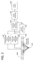
- Fig. 2 is a schematic diagram of the system of a general ultrasound device.
- the ultrasound device comprises a transmitting circuit processing system 001, a receiving circuit processing system 002, a system controller 003, an ultrasound probe 004, a received signal processor 010, an image processor 007, and an image display unit 008.
- the ultrasound probe 004 comprises a plurality of conversion elements (transducers) 005. Fig.
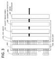
- FIG. 3 shows the details of the receiving circuit processing system 002 and the received signal processor 010, and the receiving circuit processing system 002 is configured from a delay unit 009 (delay unit), and the received signal processor 010 is configured from an adder 018, a Hilbert transformer 012, and a quadrature detector 020.
- the receiving circuit processing system 002 is configured from a delay unit 009 (delay unit)
- the received signal processor 010 is configured from an adder 018, a Hilbert transformer 012, and a quadrature detector 020.
- the ultrasound echoes from within the object are received by the receiving apertures formed from a plurality of conversion elements 005 positioned symmetrically around the arbitrary position, and converted into electrical signals in the respective conversion elements 005. Since the ultrasound echoes from within the object also reach the conversion elements as noise from positions other than the intended position, synthesis processing of extracting signals only from the intended direction and position is executed in the receiving circuit processing system 002 and the received signal processor 010.
- Delay-and-sum processing is adopted as the general synthesis processing in the ultrasound imaging apparatus.
- the delay-and-sum processing is now explained with reference to Fig. 3.
- the delay-and-sum processing is processing of the delay unit 009 performing delay processing on the ultrasound echoes from the intended object that are received from the respective conversion element 005 in asynchronous timing.
- noise components other than the intended signals are negated and suppressed.
- the signals that were subject to synthesis processing are converted into complex signals by the Hilbert transformer 012, and subsequently subject to envelope detection processing by the quadrature detector 020 and then output.
- the data group in which this output value is calculated for each time series is the image scanning line data (depth direction) at the arbitrary position.
- image scanning line data depth direction
- two-dimensional image information is output.
- a B-mode image of the object is created by subjecting the image information to LOG compression or the like in the image processor 007, and this is output to the image display unit 008 (Fig. 2).
- the processing system of an ultrasound imaging apparatus using general delay-and-sum processing is as described above.
- the adaptive signal processing is a method of efficiently calculating, as a power value, the signals from the intended direction among the signals that are received from the respective antennas.
- the ultrasound imaging apparatus performs synthesis processing of extracting signals only from the intended direction and position in the receiving circuit processing system 002 and the received signal processor 010 of Fig. 2.
- the adaptive signal processing is also characterized in that it is performed for efficiently calculating the intended signals, a system of causing the receiving circuit processing system 002 and the received signal processor 010 to be compatible with adaptive signal processing can be considered.
- Directionally Constrained Minimum Power which is a type of adaptive signal processing, is now explained.
- a linear array antenna configured from M number of conversion elements.
- set the group of the M number of signals as X(t) is shown in Formula (1).
- T represents a transposed matrix.
- the complex weight vector W In order to calculate the output from the respective signals of this array signal group, the complex weight vector W needs to be calculated.
- the weight vector W and the output y(t), and the rule for obtaining the output power Pout are shown in Formulas (2) to (4) below. Note that H represents the complex conjugate transpose, and the superscript * represents the complex conjugate.
- Rxx used in the foregoing rule is the covariance matrix of the received signal X(t), and is as shown in Formula (5). Note that E represents the time average.
- the weight vector W is adaptively changed and processed so as to optimize the output signal.
- the expression "to optimize” means to minimize the output value in a state where the sensitivity of the direction of the intended signal is constrained to 1, and the problem is formulated as shown in Formula (6) and Formula (7) below.
- the optimal weight vector Wcp can be calculated as shown in Formula (8) below. Based on this weight vector Wcp, noise signals from a direction other than the direction of the intended signals can be suppressed to the maximum extent.
- Non Patent Literature 1 As explained above, as a result of applying the adaptive signal processing to the received signals, an image having a superior azimuth resolution can be reconstructed in comparison to the conventional image reconstruction based on the delay-and-sum processing (Non Patent Literature 1). Nevertheless, with the adaptive signal processing, it is known that the processing volume in the course of calculating the inverse matrix Rxx -1 upon power conversion becomes enormous. Thus, if the adaptive signal processing is simply diverted to an ultrasound imaging apparatus, the processing volume of the apparatus becomes an unrealistic level as medical equipment. In order to resolve the foregoing problem, proposed is a system of combining the input signals to the adaptive signal processing in advance so as to reduce the number of signals (Non Patent Literature 2).
- the received signals are acquired collectively, the signals are classified by spatial frequency by the discrete Fourier transform (DFT) processing, and, after integrating the plurality of signals, adaptive signal processing is performed thereto.
- DFT discrete Fourier transform
- adaptive signal processing is performed thereto.
- relatively complex processing steps such as DFT processing and grouping for each spatial frequency need to be provided in the former processing.
- the foregoing former processing steps will also increase.
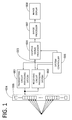
- Fig. 1 shows an example where the received signal processor 010 is replaced by the adaptive signal processor 006 in the system of the general ultrasound device shown in Fig. 2.
- Fig. 4 shows the details of the receiving circuit processing system 002 and the adaptive signal processor 006.
- the receiving circuit processing system 002 is configured from the delay unit 009
- the adaptive signal processor 006 is configured from the Hilbert transformer 012, the covariance matrix calculator 013, the spatial smoothing calculator 014, and the electric power calculator 015.
- the receiving apertures are formed using M number of conversion elements 005.
- the Hilbert transformer 012 performs Hilbert transformation to M channel signals in which their phases are matched by the delay unit 009.
- An M by M covariance matrix is created by the covariance matrix calculator 013.
- the foregoing covariance matrix is transformed into an N by N submatrix by the spatial smoothing calculator 014.
- the electric power calculator 015 adaptively calculates the optimal power based on the inverse matrix of the N by N submatrix and the constrained vector related to the signal arrival direction.
- the output calculated by the CAPON method is subject to LOG compression or the like in the image processor 007, a B-mode image of the object is created as with the general delay-and-sum processing, and this is output to the image display unit 008 (Fig. 1).
- the processing volume tends to increase relative to the number of inputs.
- the processing volume for calculating the power from a 16 by 16 sized matrix as with the foregoing simulation is 4096 L
- the processing volumes in cases where the matrix size is 8 by 8 and 4 by 4 are respectively 512 L and 64 L.
- the processing volume will become enormous if the adaptive signal processing is simply applied. Real time display is difficult with the foregoing processing volume and, since the scan time will also increase upon acquiring the volume data, the subject's physical and psychological burden cannot be ignored. This factor is a major challenge for realizing practical application.
- an object of this invention is to provide an object information acquiring apparatus capable of configuring an ultrasound image having a high azimuth resolution while suppressing the processing volume.
- the present invention provides an object information acquiring apparatus, comprising: a probe including a plurality of conversion elements which receive acoustic waves emitted from an object and convert the acoustic waves into received signals; a delay unit which matches phases of the plurality of received signals output from the plurality of conversion elements; a signal adder which groups the plurality of received signals output from the delay unit, and adds the received signals for each of the groups to obtain latter input signals; and an adaptive signal processor which generates internal image data of the object by performing adaptive signal processing on the plurality of latter input signals output from the signal adder.
- an object information acquiring apparatus capable of configuring an ultrasound image having a high azimuth resolution while suppressing the processing volume.
- Fig. 1 is a block diagram of the ultrasound imaging apparatus of the present invention.
- Fig. 2 is a block diagram of a general ultrasound imaging apparatus.
- Fig. 3 is a block diagram of an image configuration using the delay-and-sum processing.
- Fig. 4 is a block diagram of an image configuration using the adaptive signal processing.
- Fig. 5 is a block diagram of the configuration of Embodiment 1.
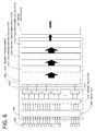
- Fig. 6 is a block diagram of the configuration of Embodiment 2.
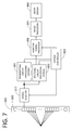
- Fig. 7 is a block diagram of the configuration of Embodiment 3.
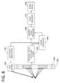
- Fig. 8 is a block diagram of the configuration of Embodiment 4.
- Fig. 9 is a diagram showing a simulation image for explaining the effect of the embodiments.
- Fig. 1 is a block diagram of the ultrasound imaging apparatus of the present invention.
- Fig. 2 is a block diagram of a general ultrasound imaging apparatus.
- Fig. 3 is a block diagram of an image configuration using the delay-and-sum processing.
- FIG. 10 is a diagram showing a simulation cross-sectional image for explaining the effect of the embodiments.
- Figs. 11 are diagrams showing simulation image for explaining the effect of Embodiment 1.
- Fig. 12 is a diagram explaining the effect of Embodiment 2.
- Figs. 13 are diagrams explaining the effect of Embodiment 3.
- the ultrasound imaging apparatus of the present invention is an apparatus which receives and processes ultrasound echoes from an object, and thereby acquires biological information as image information (image data).
- the biological image information can be presented not only as a tomographic image, but also as a three-dimensional image.
- the ultrasound imaging apparatus is mainly configured from a transmitting circuit processing system which irradiates the biological object with ultrasound waves, and a received signal processor which receives the reflected waves of the transmitted signals and configures images.
- the receiving processor is configured from the receiving circuit processing system 002 and the adaptive signal processor 006 of Fig. 1.
- the ultrasound imaging apparatus of the present invention also includes an apparatus which transmits ultrasound waves to the object and uses the foregoing ultrasound echo technology.
- the ultrasound imaging apparatus of the present invention includes an apparatus which receives acoustic waves generated in the object by irradiating the object with light (electromagnetic waves), and uses the photoacoustic effect of acquiring object information as image data.
- the ultrasound imaging apparatus of the present invention can also be referred to as an object information acquiring apparatus.
- the object information acquiring apparatus can also be referred to as a biological information acquiring apparatus.
- acoustic waves are typically ultrasound waves, and include elastic waves referred to as sound waves, ultrasound waves, photoacoustic waves, and optical ultrasound waves.
- object information is information which reflects the differences in the acoustic impedance of the tissues inside the object.
- object information shows the generation source distribution of the acoustic waves generated by optical irradiation, the initial sound pressure distribution in the object, the light energy absorption coefficient density distribution that is derived from the initial sound pressure distribution, the absorption coefficient distribution, or the concentration distribution of the substance configuring the tissues.
- the substance concentration distribution is, for example, oxygen saturation distribution or oxidized/reduced hemoglobin concentration distribution.
- the foregoing object information is also image data for generating internal images of the object through reconstruction based on the foregoing information.
- the feature of the present invention is related to a received signal processor and the transmission process of the ultrasound waves is the same as the transmission processing of general ultrasound devices described above, the detailed explanation concerning the transmission of signals is omitted.
- the characteristic configuration of the present invention foremost, several of the received signals are respectively subject to delay-and-sum processing and combined in advance in the delay unit 009 and the sum processor 011 of the received signal processing system 002.
- the adaptive signal processor 006 performs adaptive signal processing by using the latter input signal 023 that was integrated by the sum processor, and thereby reconstructs the image of biological information.
- the received signals are signals in which the ultrasound echoes from the object based on the transmitting beam are received by the respective conversion elements 005 configuring the receiving apertures.
- the adaptive signal processing is a method that is mainly used in the field of radars for adaptively changing, according to the signals, the weight coefficient (weight vector) upon synthesizing the received signals obtained with a plurality of conversion elements in order to improve the sensitivity of the intended observation direction.
- the CAPON method as one type of Directionally Constrained Minimum Power (DCMP) is adopted.
- DCMP Directionally Constrained Minimum Power
- MUSIC method Multiple Signal Classification or Estimation of Signal Parameters via Rotational Invariance Techniques
- ESPRIT method may also be used.
- This spatial averaging method is a method of obtaining a covariance matrix of the received signals, extracting a plurality of submatrices from the covariance matrix, averaging the submatrices to calculate a covariance submatrix, and calculating a weight coefficient from the covariance submatrix.
- a degree of freedom is required to a certain extent. For example, when the matrix is of a 1 by 1 size during the calculation of the weight vector, the adaptability of changing the weight from the matrix information cannot be ensured. Accordingly, a certain number of latter input signals 023 is required in order to ensure the degree of freedom.
- Fig. 9 is a reconstruction of an image of a wire phantom (diameter of 0.1 mm) by using the delay-and-sum processing in the former stage and using the CAPON method in the latter stage.
- the reconstruction method a plurality of data among the received data of 32 elements were grouped, delay-and-sum processing was performed to the signals in that group to prepare latter input signals, and the latter input signals were processed with the CAPON method.
- Fig. 10 displays the cross section beam profile of the wire.
- the number of latter input signals 023 is obtained by dividing 32, which is the number of received signals, by the number of elements of the received data to be subject to the delay-and-sum processing in the former stage, and the spatial averaging method performs averaging so as to achieve a number of rows which is half the number of the latter input signals 023.
- the number of the former delay-and-sum is 4, the number of latter input signals 023 will be 8, and a matrix of 4 by 4 will be processed by the spatial averaging method. Nevertheless, with respect to the number of times spatial averaging is performed, the results will not change significantly even when the number of times that averaging is to be performed is changed.
- condition (A) the CAPON method was performed using all 32 signals.
- condition (B) the delay-and-sum processing was performed using all 32 signals.
- condition (C) the delay-and-sum was performed using former 2 elements, and the CAPON method was performed using latter 16 inputs.
- condition (D) the delay-and-sum was performed using former 4 elements, and the CAPON method was performed using latter 8 inputs.
- condition (E) the delay-and-sum was performed using former 8 elements, and the CAPON method was performed using latter 4 inputs.
- condition (F) the delay-and-sum was performed using former 10 elements, and the CAPON method was performed using latter 3 inputs.
- condition (G) the delay-and-sum was performed using former 16 elements, and the CAPON method was performed using latter 2 inputs.
- condition (A) the beam width became narrower than condition (B), and this shows the basic effect of the CAPON method.
- condition (C) to condition (F) it was confirmed that the same level of azimuth resolution as condition (A) was obtained.
- condition (G) the beam width spreads drastically. This is because the number of latter input signals 023 was limited to 2, and, since a matrix of 1 by 1 was processed via spatial averaging, the degree of freedom during the calculation of the weight coefficient was reduced excessively. Based on these simulation results, it can be acknowledged that a sufficient azimuth resolution can be obtained if the matrix is at least 2 by 2 during the calculation of the weight coefficient. In other words, with the CAPON method in ultrasound waves that require spatial averaging, the effect of the adaptive signal processing cannot be obtained unless the number of latter input signals 023 is made to be 3 or more.
- the intensity of the output power Pout is ultimately calculated.
- the result of processing this power value in a time series becomes the image scanning line data in the intended signal direction at the arbitrary position.
- the linear scanning processing was explained above, the present invention can also be applied to convex scanning, sector scanning and radial scanning in addition to linear scanning by homologizing the direction of the intended signals described above.
- this method is also effective for 2D array probes.
- Embodiments of the present invention are now explained in light of the above.
- Embodiment 1 explains an ultrasound imaging apparatus that uses the delay-and-sum processing in the former stage and uses the adaptive signal processing (CAPON method) in the latter stage.
- CAPON method adaptive signal processing
- FIG. 1 is a schematic diagram of the system of the ultrasound device of this embodiment.
- the ultrasound device comprises a transmitting circuit processing system 001, a receiving circuit processing system 002, a system controller 003, an ultrasound probe 004, an adaptive signal processor 006, an image processor 007, and an image display unit 008.
- the ultrasound probe 004 comprises a plurality of conversion elements (transducers) 005.
- FIG. 5 shows the details of the receiving circuit processing system 002 and the adaptive signal processor 006.
- the receiving circuit processing system 002 is configured from a delay unit 009 and a plurality of sum processors 011.
- the adaptive signal processor 006 is configured from a Hilbert transformer 012, a covariance matrix calculator 013, a spatial smoothing calculator 014, and an electric power calculator 015.
- the Hilbert transformer corresponds to a complex signal converter.
- the setup information thereof is sent from the system controller 003 to the transmitting circuit processing system 001 illustrated in Fig. 1.
- the transmitting circuit processing system 001 decides the elements to transmit the ultrasound waves and their respective delay times. Subsequently, the transmitting circuit processing system 001 sends electrical signals for driving the corresponding conversion elements 005 in the ultrasound probe 004. These electrical signals are converted into displacement signals by the conversion element 005 and then propagated as ultrasound waves toward the object.
- the ultrasound waves that were transmitted and propagated as described above are reflected or scattered by the object and once again return to the conversion elements 005 as ultrasound echoes.
- the ultrasound echoes being converted into electrical signals (received signals) in the 32 conversion elements 005 forming the receiving apertures among the above, the biological information of the object can be acquired as 32 electrical signals.
- These received signals are sent to the receiving circuit processing system 002.
- the receiving circuit processing system 002 determines the delay time of the received signals based on the depth information of the received data, and performs delay processing on the respective received signals. This delay processing is performed in the delay unit 009 in the receiving circuit processing system 002 illustrated in Fig.
- processing is performed so as to match the phases of the signals arising from the ultrasound echoes from the object that were received by the respective conversion elements 005.
- the same processor may be diverted to the respective delay units for transmissions and receptions.
- the respective signals that were subject to the delay processing are combined for every 4 channels, which is a number that is set in advance, and sent to the respective signal adders 011.
- the signals of the 4 channels with matched phases are added in the signal adder 011, and the latter input signals 023 combined into 8 channels are sent to the adaptive signal processor 006.
- the Hilbert transformer 012 transforms the respective latter input signals 023 of the 8 channels into complex signals, whereby an 8-channel complex vector is created.
- the covariance matrix calculator 013 a complex covariance matrix of a 4 by 4 size is calculated.
- the spatial averaging unit 014 the complex covariance matrix is averaged into a covariance submatrix of a 4 by 4 size.
- the weight vector is adaptively calculated from the matrix obtained by the spatial averaging unit and the weight and the direction of the designated intended signals, and that weight vector is used to generate an output power Pout.
- the delay unit 009 if the amount of delay is caused to coincide in all 32 channels and not for every 4 channels, there is no need to set a vector for designating the direction of the intended signals. Nevertheless, if the phases of the respective latter input signals 023 of the 8 channels that were subject to delay-and-sum have not been matched, then it is necessary to calculate the intensity of the output power Pout by using a constrained vector which designates the direction of the respective intended signals.
- the output power Pout is sent to the image processor 007, and subject to processing such as LOG compression so as to create image scanning line data.
- processing such as LOG compression so as to create image scanning line data.
- a two-dimensional ultrasound image is created.
- the ultrasound image created by the image processor 007 is sent to the image display unit 008 such as an LCD, and the image is thereby visibly displayed.
- the image display unit 008 is not limited to an LCD, and other image display units such as a CRT, a PDP, an FED, or an OLED may also be used.
- the main signal flow is as described above.
- the results of reconstructing a wire (diameter of 0.1 mm) image in a phantom for ultrasound waves based on the foregoing system are shown in Fig. 11B.
- the image in which 32 signals were reconstructed with the CAPON method is shown in Fig. 11A
- the image in which 32 signals were reconstructed with the delay-and-sum processing is shown in Fig. 11C.
- the beam width in the orientation direction at roughly -1.94 dB of the TOP value of these wire images was 0.5 mm in Fig. 11A, 0.5 mm in Fig. 11B, and 0.75 mm in Fig. 11C. Consequently, it was possible to confirm that the image quality yielded a favorable azimuth resolution in comparison to the case of only performing the delay-and-sum processing, and that an image quality that is in no way inferior to the case of only performing the adaptive signal processing could be realized. Moreover, it was possible to reduce the processing volume of this embodiment to roughly 1/64 in comparison to the case shown in Fig. 11A.
- the processing was performed with 32 as the number of input signals, 4 as the number of times the former delay-and-sum processing is performed, 8 as the number of latter input signals, and 4 by 4 as the vector size after the spatial averaging, but other values may be used instead of the foregoing values.
- Embodiment 2 (Configuration of ultrasound device) Embodiment 2 of the present invention is now explained.
- the system of Fig. 1 explained in Embodiment 1 may be used, but different processing is performed in the receiving circuit processing system 002.
- Fig. 6 shows the configuration of this embodiment, and a signal selector 016 is provided between the delay unit 009 and the sum processor 011 illustrated in Fig. 5 of Embodiment 1.
- Fig. 12 is a diagram for explaining this embodiment in correspondence with aperture control, and shows the relationship of the target depth on the image scanning line 019 in the object 024 and the operation of the signal selector 016.
- aperture control is sometimes performed to suppress a side lobe.
- Aperture control is the processing of adjusting the number of the plurality of transmitting conversion elements 005 and receiving conversion elements 005 configuring the transmitting/receiving apertures of the ultrasound wave in correspondence with the measured depth, and the number of transmitting/receiving elements is decreased as the measured depth becomes smaller.
- the decrease of the number of elements is not achieved by generally thinning out the conversion elements, and is achieved by narrowing the range of the conversion elements. Note that, since the performance of aperture control is irrelevant with the transmitted signals of the present invention, only the subject matter concerning the received signals is explained.
- the received signals that were converted into electrical signals by the conversion elements 005 illustrated in Fig. 6 are sent to the delay unit 009 of the receiving circuit processing system 002, and delay processing is performed based on the signals from the system controller 003.
- the respective signals that were subject to delay processing are sent to the signal selector 016.
- the signal selector 016 allocates all received signals to the signal adder 011 divided into the latter 8 blocks based on the selected signals sent from the system controller 003.
- the number of conversion elements 005 used for the synthesis processing is reduced as 32, 24, 16, 8 as the object depth becomes smaller, and evenly sorted to the 8 signal adders 011.
- the latter input signals 023 of 8 channels are created in the signal adder 011, and, by subsequently performing the same processing as Embodiment 1, image is reconstructed. Note that the same processor may be diverted to the respective delay units for transmissions and receptions.
- the number of conversion elements 005 to be referred to in the synthesis processing can be adjusted in correspondence with the target depth on the image scanning line 019, whereby aperture control is enabled.
- a predetermined number of conversion elements corresponding to the range of a predetermined depth may be set forth in advance according to the characteristics of the probe or the conversion elements, the accuracy of image reconstruction, and the type of object. Otherwise, the number of conversion elements can be adjusted by experimentally performing measurement and image reconstruction.
- the range of the predetermined depth and the number of conversion elements corresponding thereto may be stored in a memory or the like and referred to during image reconstruction.
- Embodiment 3 of the present invention relates to an ultrasound device which absorbs the difference in the pin arrangement or number of element channels of the ultrasound probe based on probe information.
- Fig. 7 shows the device configuration of this embodiment, and a signal selector 017 is provided between the transmitting circuit processing system 001/receiving circuit processing system 002 and the ultrasound probe 004 in the system shown in Fig. 1 of Embodiment 1. Note that the details of the receiving circuit processing system 002 and the adaptive signal processor 006 in this embodiment are the same as Embodiment 1 and are as shown in Fig. 5.
- the setup information thereof is sent from the system controller 003 to the transmitting circuit processing system 001.
- the transmitting circuit processing system 001 determines the type of transmitting elements and the respective delays times to be sent to those elements based on the foregoing information, and sends, to the signal selector 017, the electric signals for driving the corresponding conversion elements 005 in the ultrasound probe 004.
- the signal selector 017 sends the electrical signals to each of the corresponding conversion elements 005 based on the information of the ultrasound probe 004 or the depth information of the ultrasound signals sent from the system controller 001.
- the converted element 005 the sent electrical signals are converted into displacement signals, and propagated to the object as ultrasound waves.
- the ultrasound echoes reflected off the object are received by the respective conversion elements 005, and acquired as electrical signals.
- the received signals are once again sent to the signal selector 017.
- the signal selector 017 chooses the received signals based on the information of the ultrasound probe 004 or the depth information sent from the system controller 001, and sends them to the delay unit 009 (Fig. 5) in the receiving circuit processing system 002.
- the delay unit performs delay processing only to the sent signals.
- the respective signals subject to delay processing are sent to a pre-set sum processor 011 (Fig. 5). Note that the same processor may be diverted to the respective delay units for transmissions and receptions. As a result of subsequently performing the same processing as Embodiment 1, the image is reconstructed.
- Fig. 13 shows the ultrasound probe 004, the conversion element 005, the signal selector 017, and the receiving circuit processing system 002 of Fig. 7.
- the ultrasound probe 004 is connected with the ultrasound imaging apparatus body via the probe connector 025, and the arrangement of the pins of the probe connector corresponding to the respective conversion elements 005 will differ depending on type of probe.
- the signal selector 017 comprises a selector switch 026 for sorting the signals.
- Fig. 13A and Fig. 13B are used to explain the operations of respectively using the ultrasound probes 004 in which the number of conversion elements 005 is the same but the pin arrangement of the probe connector 025 is different.
- the selector switch rearranges the pin arrangement so as to attain a match. Consequently, the two types of ultrasound probes can perform the same processing.
- two linear probes of 128 channels having different pin arrangements of the connector were prepared for confirmation. Since the band of the respective probes and the sensitivity of the respective elements are different, it is not possible to obtain an image that is completely the same, but it was confirmed that a high resolution image using the CAPON method in the same system can be reconstructed.
- Figs. 13A and 13C are used to explain the operations of using the ultrasound probes 004 having a different number of conversion elements 005 and a different pin arrangement of the probe connector 025.
- the selector switch rearranges the pin arrangement to a setting corresponding to the latter synthesis processing. Even in cases where the number of signals for synthesizing an image is different, it is possible to evenly sort the signals to the sum processors 011, and output an image. Specifically, linear probes of 256 channels and 128 channels were prepared for confirmation.
- Figs. 13A and 13D are used to explain the operation corresponding to aperture control.
- Fig. 13A corresponds to processing of a deep part of the object and
- Fig. 13D corresponds to processing of a shallow part of the object.
- the selector switch rearranges the pin arrangement to a setting corresponding to the latter synthesis processing.
- the number of latter input signals 023 of the probes become equal, and Fig. 13D can maximize the effects of the adaptive signal processing, and perform the same processing as Embodiment 2.
- an image can be reconstructed with the same processing system even in cases of using ultrasound probes having a different number of channels and a different pin arrangement, and it is possible to deal with situations of changing the number of elements in aperture control or the like.
- the number of transmitted signals was changed as 32, 24, 16, 8 based on signal switching. Consequently, it was possible to realize a high resolution image using the CAPON method in the same system, and also realize the operation of aperture control.
- Embodiment 4 of the present invention relates to a photoacoustic imaging apparatus which receives photoacoustic signals (photoacoustic waves), and performs image reconstruction based on adaptive signal processing.
- Fig. 8 shows the device configuration of this embodiment, and a light source drive system 021 and a light source 022 are provided in substitute for the transmitting circuit processing system 001 of the system shown in Fig. 1 of Embodiment 1.
- the setup information thereof is sent from the system controller 003 to the light source drive system 021 illustrated in Fig. 8.
- the light source drive system 021 drives the light source 022 based on the foregoing setup information, and irradiates the object with pulsed electromagnetic waves such as pulsed laser.
- the acoustic waves emitted from within the object based on the foregoing irradiation are received by the conversion element 005.
- the image is reconstructed.
- the input signals are combined every 4 signals, and it was possible to reduce the processing volume to roughly 1/64 in comparison to the case of processing all signals based on the CAPON method.
Landscapes
- Engineering & Computer Science (AREA)
- Physics & Mathematics (AREA)
- Radar, Positioning & Navigation (AREA)
- Remote Sensing (AREA)
- Computer Networks & Wireless Communication (AREA)
- General Physics & Mathematics (AREA)
- Acoustics & Sound (AREA)
- Health & Medical Sciences (AREA)
- Life Sciences & Earth Sciences (AREA)
- Pathology (AREA)
- Animal Behavior & Ethology (AREA)
- Biomedical Technology (AREA)
- Heart & Thoracic Surgery (AREA)
- Medical Informatics (AREA)
- Molecular Biology (AREA)
- Surgery (AREA)
- Biophysics (AREA)
- General Health & Medical Sciences (AREA)
- Public Health (AREA)
- Veterinary Medicine (AREA)
- Ultra Sonic Daignosis Equipment (AREA)
- Measurement Of Velocity Or Position Using Acoustic Or Ultrasonic Waves (AREA)
- Investigating Or Analyzing Materials By The Use Of Ultrasonic Waves (AREA)
Abstract
La présente invention porte sur un appareil d'acquisition d'informations d'objet comprenant une sonde comprenant une pluralité d'éléments de conversion qui reçoivent des ondes acoustiques émises à partir d'un objet et convertissent les ondes acoustiques en signaux reçus, une unité de retard qui adapte des phases de la pluralité de signaux reçus émis à partir de la pluralité d'éléments de conversion, un additionneur de signaux qui ajoute la pluralité de signaux reçus émis à partir de l'unité de retard, pour chaque groupe afin d'obtenir des signaux d'entrée ultérieurs, et un processeur de signal adaptatif qui génère des données d'image internes de l'objet par réalisation d'un traitement de signal adaptatif sur la pluralité de signaux d'entrée ultérieurs émis à partir d'une pluralité des additionneurs de signaux.
Priority Applications (1)
| Application Number | Priority Date | Filing Date | Title |
|---|---|---|---|
| US14/113,614 US20140051970A1 (en) | 2011-05-10 | 2012-04-26 | Object information acquiring apparatus |
Applications Claiming Priority (2)
| Application Number | Priority Date | Filing Date | Title |
|---|---|---|---|
| JP2011105317A JP5864894B2 (ja) | 2011-05-10 | 2011-05-10 | 被検体情報取得装置および信号処理装置 |
| JP2011-105317 | 2011-05-10 |
Publications (2)
| Publication Number | Publication Date |
|---|---|
| WO2012153479A2 true WO2012153479A2 (fr) | 2012-11-15 |
| WO2012153479A3 WO2012153479A3 (fr) | 2013-01-24 |
Family
ID=46208698
Family Applications (1)
| Application Number | Title | Priority Date | Filing Date |
|---|---|---|---|
| PCT/JP2012/002874 Ceased WO2012153479A2 (fr) | 2011-05-10 | 2012-04-26 | Appareil d'acquisition d'informations d'objet |
Country Status (3)
| Country | Link |
|---|---|
| US (1) | US20140051970A1 (fr) |
| JP (1) | JP5864894B2 (fr) |
| WO (1) | WO2012153479A2 (fr) |
Cited By (2)
| Publication number | Priority date | Publication date | Assignee | Title |
|---|---|---|---|---|
| US20160003942A1 (en) * | 2014-07-01 | 2016-01-07 | Furuno Electric Co., Ltd. | Device, method and program for processing signal, underwater detecting device and radar apparatus |
| US9924876B2 (en) | 2013-03-29 | 2018-03-27 | Canon Kabushiki Kaisha | Object information acquiring apparatus and method of controlling same |
Families Citing this family (14)
| Publication number | Priority date | Publication date | Assignee | Title |
|---|---|---|---|---|
| JP5814556B2 (ja) | 2011-02-04 | 2015-11-17 | キヤノン株式会社 | 信号処理装置 |
| JP2012235832A (ja) | 2011-05-10 | 2012-12-06 | Canon Inc | 被検体情報取得装置 |
| JP5850640B2 (ja) | 2011-05-10 | 2016-02-03 | キヤノン株式会社 | 被検体情報取得装置及び被検体情報取得方法 |
| JP5847490B2 (ja) | 2011-08-25 | 2016-01-20 | キヤノン株式会社 | 被検体情報取得装置 |
| US9500627B2 (en) * | 2012-06-26 | 2016-11-22 | The Boeing Company | Method for ultrasonic inspection of irregular and variable shapes |
| JP6071582B2 (ja) | 2013-01-23 | 2017-02-01 | キヤノン株式会社 | 被検体情報取得装置およびその制御方法 |
| JP6238556B2 (ja) | 2013-04-25 | 2017-11-29 | キヤノン株式会社 | 被検体情報取得装置およびその制御方法、ならびに探触子 |
| JP6288998B2 (ja) * | 2013-09-17 | 2018-03-07 | キヤノンメディカルシステムズ株式会社 | 超音波診断装置及び超音波イメージングプログラム |
| KR102040853B1 (ko) * | 2015-03-27 | 2019-11-05 | 알피니언메디칼시스템 주식회사 | 공간 스무딩 연산이 간단한 빔포밍 장치, 초음파 이미징 장치 및 빔포밍 방법 |
| US11246492B2 (en) | 2015-08-31 | 2022-02-15 | Canon Kabushiki Kaisha | Apparatus performing examination utilizing photoacoustic effect, examination support method, and program |
| JP6776766B2 (ja) * | 2016-09-26 | 2020-10-28 | セイコーエプソン株式会社 | 超音波測定装置および超音波測定装置の制御方法 |
| JP7195759B2 (ja) | 2018-04-20 | 2022-12-26 | キヤノン株式会社 | 光音響装置および被検体情報取得方法 |
| CN112650707A (zh) * | 2019-10-10 | 2021-04-13 | 上海科技大学 | 多通道光声信号延迟装置、系统、信号处理方法、终端、介质 |
| US11525810B2 (en) | 2020-02-20 | 2022-12-13 | The Boeing Company | Method for ultrasonic inspection of structure having radiused surface using multi-centric radius focusing |
Citations (1)
| Publication number | Priority date | Publication date | Assignee | Title |
|---|---|---|---|---|
| JP2011105317A (ja) | 2009-11-13 | 2011-06-02 | Toppan Printing Co Ltd | 包装容器及びこの包装容器を用いた食品包装体の製造方法 |
Family Cites Families (7)
| Publication number | Priority date | Publication date | Assignee | Title |
|---|---|---|---|---|
| JPH0677590B2 (ja) * | 1985-07-23 | 1994-10-05 | 松下電器産業株式会社 | 超音波探触子接続用アダプタ |
| US6089096A (en) * | 1998-07-01 | 2000-07-18 | Aloka Co., Ltd. | Elevation focusing by beamformer channel sharing |
| JP4087739B2 (ja) * | 2003-04-22 | 2008-05-21 | アロカ株式会社 | 超音波診断装置 |
| JP4406226B2 (ja) * | 2003-07-02 | 2010-01-27 | 株式会社東芝 | 生体情報映像装置 |
| US7998072B2 (en) * | 2003-12-19 | 2011-08-16 | Siemens Medical Solutions Usa, Inc. | Probe based digitizing or compression system and method for medical ultrasound |
| JP5483905B2 (ja) * | 2009-03-03 | 2014-05-07 | キヤノン株式会社 | 超音波装置 |
| JP5653057B2 (ja) * | 2009-05-27 | 2015-01-14 | キヤノン株式会社 | 測定装置 |
-
2011
- 2011-05-10 JP JP2011105317A patent/JP5864894B2/ja not_active Expired - Fee Related
-
2012
- 2012-04-26 WO PCT/JP2012/002874 patent/WO2012153479A2/fr not_active Ceased
- 2012-04-26 US US14/113,614 patent/US20140051970A1/en not_active Abandoned
Patent Citations (1)
| Publication number | Priority date | Publication date | Assignee | Title |
|---|---|---|---|---|
| JP2011105317A (ja) | 2009-11-13 | 2011-06-02 | Toppan Printing Co Ltd | 包装容器及びこの包装容器を用いた食品包装体の製造方法 |
Non-Patent Citations (2)
| Title |
|---|
| IEEE TRANS ULTRASON FERROELECTR FREQ CONTROL., vol. 54, no. 8, August 2007 (2007-08-01), pages 1606 - 13 |
| IEEE TRANS ULTRASON FERROELECTR FREQ CONTROL., vol. 56, no. 10, October 2009 (2009-10-01), pages 2187 - 97 |
Cited By (3)
| Publication number | Priority date | Publication date | Assignee | Title |
|---|---|---|---|---|
| US9924876B2 (en) | 2013-03-29 | 2018-03-27 | Canon Kabushiki Kaisha | Object information acquiring apparatus and method of controlling same |
| US20160003942A1 (en) * | 2014-07-01 | 2016-01-07 | Furuno Electric Co., Ltd. | Device, method and program for processing signal, underwater detecting device and radar apparatus |
| US9857464B2 (en) * | 2014-07-01 | 2018-01-02 | Furuno Electric Co., Ltd. | Device, method and program for processing signal, underwater detecting device and radar apparatus |
Also Published As
| Publication number | Publication date |
|---|---|
| JP5864894B2 (ja) | 2016-02-17 |
| WO2012153479A3 (fr) | 2013-01-24 |
| JP2012235830A (ja) | 2012-12-06 |
| US20140051970A1 (en) | 2014-02-20 |
Similar Documents
| Publication | Publication Date | Title |
|---|---|---|
| WO2012153479A2 (fr) | Appareil d'acquisition d'informations d'objet | |
| US12121394B2 (en) | Coherent spread-spectrum coded waveforms in synthetic aperture image formation | |
| US20240310516A1 (en) | Spatial and temporal encoding of transmission for full synthetic transmit aperture imaging | |
| JP5490198B2 (ja) | 幅広ビーム映像化 | |
| CN104169739B (zh) | 超声成像中的扩频编码波形 | |
| JP5865050B2 (ja) | 被検体情報取得装置 | |
| AU2014318907A1 (en) | Coherent spread-spectrum coded waveforms in synthetic aperture image formation | |
| US9146305B2 (en) | Subject information acquiring apparatus and subject information acquiring method | |
| EP2700976B1 (fr) | Appareil d'imagerie ultrasonore et procédé d'imagerie ultrasonore | |
| JP2012235831A (ja) | 被検体情報取得装置及び被検体情報取得方法 | |
| US11413012B2 (en) | Ultrasound signal processing device and ultrasound signal processing method | |
| JP2016104279A (ja) | 被検体情報取得装置及び被検体情報取得方法 | |
| CA3080561C (fr) | Codage spatial et temporel de formes d'onde acoustiques pour imagerie d'ouverture de transmission synthetique complete | |
| Li | Large-Pitch Methods for 2D/3D Synthetic Transmit Aperture Ultrasound Imaging | |
| HK1226279B (zh) | 在合成孔徑圖像形成中的相干展頻 |
Legal Events
| Date | Code | Title | Description |
|---|---|---|---|
| 121 | Ep: the epo has been informed by wipo that ep was designated in this application |
Ref document number: 12725886 Country of ref document: EP Kind code of ref document: A2 |
|
| WWE | Wipo information: entry into national phase |
Ref document number: 14113614 Country of ref document: US |
|
| NENP | Non-entry into the national phase |
Ref country code: DE |
|
| 122 | Ep: pct application non-entry in european phase |
Ref document number: 12725886 Country of ref document: EP Kind code of ref document: A2 |