WO2012153540A1 - Structure de connexion à baïonnette entre une partie d'embouchure de récipient et un bouchon - Google Patents
Structure de connexion à baïonnette entre une partie d'embouchure de récipient et un bouchon Download PDFInfo
- Publication number
- WO2012153540A1 WO2012153540A1 PCT/JP2012/003096 JP2012003096W WO2012153540A1 WO 2012153540 A1 WO2012153540 A1 WO 2012153540A1 JP 2012003096 W JP2012003096 W JP 2012003096W WO 2012153540 A1 WO2012153540 A1 WO 2012153540A1
- Authority
- WO
- WIPO (PCT)
- Prior art keywords
- cap
- container
- bayonet
- connection structure
- slip
- Prior art date
- Legal status (The legal status is an assumption and is not a legal conclusion. Google has not performed a legal analysis and makes no representation as to the accuracy of the status listed.)
- Ceased
Links
Images



Classifications
-
- B—PERFORMING OPERATIONS; TRANSPORTING
- B65—CONVEYING; PACKING; STORING; HANDLING THIN OR FILAMENTARY MATERIAL
- B65D—CONTAINERS FOR STORAGE OR TRANSPORT OF ARTICLES OR MATERIALS, e.g. BAGS, BARRELS, BOTTLES, BOXES, CANS, CARTONS, CRATES, DRUMS, JARS, TANKS, HOPPERS, FORWARDING CONTAINERS; ACCESSORIES, CLOSURES, OR FITTINGS THEREFOR; PACKAGING ELEMENTS; PACKAGES
- B65D43/00—Lids or covers for rigid or semi-rigid containers
- B65D43/02—Removable lids or covers
-
- B—PERFORMING OPERATIONS; TRANSPORTING
- B65—CONVEYING; PACKING; STORING; HANDLING THIN OR FILAMENTARY MATERIAL
- B65D—CONTAINERS FOR STORAGE OR TRANSPORT OF ARTICLES OR MATERIALS, e.g. BAGS, BARRELS, BOTTLES, BOXES, CANS, CARTONS, CRATES, DRUMS, JARS, TANKS, HOPPERS, FORWARDING CONTAINERS; ACCESSORIES, CLOSURES, OR FITTINGS THEREFOR; PACKAGING ELEMENTS; PACKAGES
- B65D41/00—Caps, e.g. crown caps or crown seals, i.e. members having parts arranged for engagement with the external periphery of a neck or wall defining a pouring opening or discharge aperture; Protective cap-like covers for closure members, e.g. decorative covers of metal foil or paper
- B65D41/02—Caps or cap-like covers without lines of weakness, tearing strips, tags, or like opening or removal devices
- B65D41/04—Threaded or like caps or cap-like covers secured by rotation
- B65D41/0471—Threaded or like caps or cap-like covers secured by rotation with means for positioning the cap on the container, or for limiting the movement of the cap, or for preventing accidental loosening of the cap
-
- B—PERFORMING OPERATIONS; TRANSPORTING
- B05—SPRAYING OR ATOMISING IN GENERAL; APPLYING FLUENT MATERIALS TO SURFACES, IN GENERAL
- B05B—SPRAYING APPARATUS; ATOMISING APPARATUS; NOZZLES
- B05B11/00—Single-unit hand-held apparatus in which flow of contents is produced by the muscular force of the operator at the moment of use
- B05B11/0005—Components or details
- B05B11/0008—Sealing or attachment arrangements between sprayer and container
- B05B11/001—Snap-on-twist-off type connections
-
- B—PERFORMING OPERATIONS; TRANSPORTING
- B65—CONVEYING; PACKING; STORING; HANDLING THIN OR FILAMENTARY MATERIAL
- B65D—CONTAINERS FOR STORAGE OR TRANSPORT OF ARTICLES OR MATERIALS, e.g. BAGS, BARRELS, BOTTLES, BOXES, CANS, CARTONS, CRATES, DRUMS, JARS, TANKS, HOPPERS, FORWARDING CONTAINERS; ACCESSORIES, CLOSURES, OR FITTINGS THEREFOR; PACKAGING ELEMENTS; PACKAGES
- B65D41/00—Caps, e.g. crown caps or crown seals, i.e. members having parts arranged for engagement with the external periphery of a neck or wall defining a pouring opening or discharge aperture; Protective cap-like covers for closure members, e.g. decorative covers of metal foil or paper
- B65D41/02—Caps or cap-like covers without lines of weakness, tearing strips, tags, or like opening or removal devices
- B65D41/04—Threaded or like caps or cap-like covers secured by rotation
- B65D41/06—Threaded or like caps or cap-like covers secured by rotation with bayonet cams, i.e. removed by first pushing axially to disengage the cams and then rotating
-
- B—PERFORMING OPERATIONS; TRANSPORTING
- B05—SPRAYING OR ATOMISING IN GENERAL; APPLYING FLUENT MATERIALS TO SURFACES, IN GENERAL
- B05B—SPRAYING APPARATUS; ATOMISING APPARATUS; NOZZLES
- B05B11/00—Single-unit hand-held apparatus in which flow of contents is produced by the muscular force of the operator at the moment of use
- B05B11/01—Single-unit hand-held apparatus in which flow of contents is produced by the muscular force of the operator at the moment of use characterised by the means producing the flow
- B05B11/10—Pump arrangements for transferring the contents from the container to a pump chamber by a sucking effect and forcing the contents out through the dispensing nozzle
- B05B11/1001—Piston pumps
- B05B11/1009—Piston pumps actuated by a lever
- B05B11/1011—Piston pumps actuated by a lever without substantial movement of the nozzle in the direction of the pressure stroke
Definitions
- the present invention relates to a bayonet connection structure between a cap and a cap to which a pump dispenser is attached via a cap.
- a pump dispenser is generally manufactured separately from a container and is used as an ejection container having an ejection function by being connected to the mouth of the container via a cap.
- the container (bottle) mouth (neck) and the cap have various connection structures such as screwing and fitting, among which two operations, "pushing action” and “rotating action”.
- Patent Document 1 cap attachment mechanism describes the following.
- At least three bayonet members are formed on the outer periphery of the neck of the bottle, and the same number of lugs as the bayonet members are formed on the outer periphery of the cap, and are attached and detached by three or more sets of bayonet mechanisms.
- the cap does not sway compared to that using two or more sets of bayonet mechanisms, thus ensuring a secure seal between the bottle and the cap.
- Patent Document 1 the cap mounting mechanism described in Patent Document 1 is designed to perform both the cap retaining function and the rotation preventing function with the bayonet member and the lug. There is a disadvantage that the bayonet member on the bottle side is crushed or worn away.
- This invention is made
- An object is to provide a die connection structure.
- the present inventor has intensively studied to solve the above-mentioned problems.
- the present inventors have found that the above-mentioned problems can be solved by using separate mechanisms for preventing slipping and preventing rotation, and have completed the present invention. .
- the present invention is (1) a bayonet-type connection structure between a mouth of a container to which a pump dispenser is attached via a cap and the cap, and the cap is spaced circumferentially on an inner peripheral surface thereof.
- a plurality of slip-off prevention pawls, and one of the plurality of slip-out prevention pawls is a slip-off prevention pawl that can be elastically displaced in the radial direction.
- a plurality of anti-rotation protrusions extending in the axial direction, and the mouth portion of the container has the same number of omission preventions that engage with the outer oval surfaces of the hollow cylindrical portion of the omission caps of the cap.
- An anti-rotation stopper extending in the axial direction is provided adjacent to a clockwise end of the slip-off prevention pawl engagement portion that includes a pawl engagement portion and engages with each of the other slip-off prevention pawls, Cap rotation Wherein the rotation prevention projection of the cap is provided with an anti-rotation ribs extending in the axial direction to overcome lies in bayonet connection structure between the container mouth portion and the cap.
- the plurality of removal prevention claws are three, the rotation prevention protrusions are two, the plurality of removal prevention claw engaging portions are three, and the rotation prevention stopper is 2
- the rotation prevention rib is two pieces.
- the present invention is (3) the container according to (1) or (2), wherein the pump dispenser includes a case main body and a cap that support a pump, and the case main body and the cap are integrally formed. It exists in the bayonet type connection structure of a mouth part and a cap.
- the pump dispenser includes a case main body and a cap that support a pump, the case main body and the cap are formed as separate members, and the case main body and the cap are attached by fitting.
- the case main body and the cap are formed as separate members, and the case main body and the cap are attached by fitting.
- the present invention resides in (5) a bayonet-type connection structure between a mouth portion of a container and a cap according to any one of (1) to (4), wherein the pump dispenser is a trigger type pump dispenser. .
- the present invention resides in (6) a bayonet-type connection structure between a container mouth and a cap according to any one of (1) to (4) above, wherein the pump dispenser is a push-type pump dispenser. .
- the present invention resides in (7) a bayonet-type connection structure between a container mouth and a cap according to any one of (1) to (4) above, wherein the pump dispenser is an accumulator pump dispenser. .
- the bayonet-type connection structure between the mouth portion of the container and the cap has a plurality of circumferentially spaced apart inner circumferential surfaces thereof.
- An escape prevention pawl is provided, and one of the plurality of escape prevention pawls is an escape prevention pawl that is elastically displaceable in the radial direction.
- the mouth of the container is provided with the same number of anti-retraction pawl engaging portions on the outer peripheral surface of the hollow cylindrical portion with which the cap anti-retraction pawls engage.
- An anti-rotation stopper extending in the axial direction is provided adjacent to the clockwise end of the slip-off prevention pawl engaging portion that engages with each of the prevention pawls, and the shaft over which the anti-rotation protrusion of the cap rides when the cap rotates.
- Anti-rotation extending in the direction Is provided with the blanking, It is possible to prevent the rotation prevention stopper extending in the axial direction on the mouth side of the container and the rotation prevention rib extending in the axial direction from being crushed or worn out.
- the pump dispenser also has a case body and a cap that support the pump. If the case body and the cap are integrally molded, the case body and the cap can be molded from a synthetic resin with fewer molding dies. Cost can be kept low.
- the pump dispenser includes a case main body and a cap that support the pump, and the case main body and the cap are formed as separate members, and the case main body and the cap are attached to each other by fitting. It can be molded from a suitable synthetic resin.
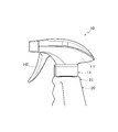
- FIG. 1 is a side view showing an embodiment of a bayonet connection structure between a mouth portion of a container and a cap according to the present invention.
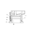
- FIG. 2 is a vertical sectional view showing a bayonet-type connection structure between the mouth portion of the container and the cap shown in FIG.
- FIG. 3 is a vertical sectional view of the cap shown in FIG.
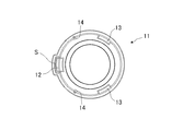
- FIG. 4 is a plan view seen from below the cap shown in FIG.
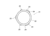
- FIG. 5 is a plan view of the hollow cylindrical portion of the mouth portion of the container shown in FIG.
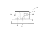
- FIG. 6 is a side view of the mouth of the container shown in FIG.
- FIG. 7 is a horizontal sectional view of the mouth and the cap showing a state in which the cap is inserted in the mouth of the container shown in FIG. 1 in the vertical direction.
- FIG. 8 is an enlarged view of a circle X portion in FIG.
- FIG. 9 is a horizontal cross-sectional view of the mouth and the cap in a state where the cap is rotated clockwise from a state where the cap is inserted in the mouth of the container shown in FIG.
- FIG. 10 is an enlarged view of a circle Y portion of FIG.
- FIG. 11 is a side view showing a state before the cap is fitted in the mouth of the container in the vertical direction.
- FIG. 12 is a side view showing a state where the cap is rotated in the clockwise direction after the cap is fitted in the mouth of the container in the vertical direction.
- FIG. 13 is a partial cross-sectional side view in which a bayonet type connection structure between a mouth portion of a container and a cap according to the present invention is applied to a push-type pump dispenser.
- the bayonet type connection structure between the mouth portion 21 of the container 20 and the cap 11 has a unique structure.
- the cap 11 has two types of portions having different functions of the anti-falling pawls 12 and 13 and the anti-rotation protrusion 14. That is, the cap 11 is provided with a plurality of slip-off preventing claws 12, 13 on the inner peripheral surface thereof at intervals in the circumferential direction, and one of the plurality of slip-off preventing claws 12, 13 can be elastically displaced in the radial direction.
- the anti-retraction pawl 12 is provided with an anti-rotation projection 14 extending in the axial direction between the elastic anti-displacement anti-loss pawl 12 and the other anti-extraction pawls 13 and 13.
- the mouth portion 21 of the container 20 has a slip-off preventing pawl engaging portion 23 (having a rotation-preventing stopper 24) and a rotation-preventing rib 25 that function in correspondence with the cap-stopping pawls 12 and 13 and the rotation-preventing protrusion 14 of the cap 11. It has.
- the mouth portion 21 of the container 20 is provided with the same number of removal prevention pawl engagement portions 23 on the outer peripheral surface of the hollow cylindrical portion 22 with which the plurality of removal prevention claws 12 and 13 of the cap 11 are engaged.
- An anti-rotation stopper 24 extending in the axial direction is provided adjacent to the end portion in the clockwise direction of the anti-detachment pawl engaging portion 23 that engages with the anti-disengagement pawl 13. Further, when the cap 11 rotates, the cap 11
- the anti-rotation protrusion 25 is provided with an anti-rotation rib 25 extending in the axial direction.
- FIG. 1 is a side view showing an embodiment of a bayonet connection structure between a mouth portion 21 of a container 20 and a cap 11 of a trigger type pump dispenser 10 according to the present invention.
- the trigger type pump dispenser 10 is pivotally pivotable to a case main body 11 ′ (including built-in portions such as a cylinder, a piston, and a base portion) that supports the pump. It has a trigger 10 'to be worn.
- FIG. 2 is a vertical sectional view showing a bayonet-type connection structure between the mouth portion 21 and the cap 11 of the container 20 shown in FIG. 1, and is an elastically displaceable slip-off preventing claw 12 and a slip-off preventing pawl engaging portion of the mouth portion 21. 23 shows an engaged state.
- FIG. 3 and 4 show a cap 11, which comprises an elastically displaceable slip-off pawl 12, two slip-off preventive pawls 13, and two axially extending anti-rotation projections 14.
- FIG. 5 and 6 show the mouth portion 21, and the mouth portion 21 is provided on the outer periphery of the hollow cylindrical portion 22 with three slip-off preventing pawl engaging portions 23 and two axially preventing rotation stoppers 24. Two anti-rotation ribs 25 extending in the axial direction are provided.
- cap 11 shows a state in which the cap 11 is fitted in the mouth portion 21 in the axial direction.
- the cap 11 and the slip-off preventing pawl 13 that can be elastically displaced do not interfere with the slip-off preventing pawl engaging portion 23 of the mouth portion 21.
- the cap 11 is fitted in the mouth portion 21 in the axial direction.
- 9 and 10 show a state in which the cap 11 is rotated in the clockwise direction after the cap 11 is fitted in the mouth portion 21 in the axial direction. 7 and 8, when the cap 11 is strongly rotated in the clockwise direction, the anti-rotation protrusion 14 extending in the axial direction of the cap 11 gets over the anti-rotation rib 25 extending in the axial direction of the mouth portion 21. At this time, the person who operates the cap 11 feels a response such as a click feeling, a collision feeling or the like on the way.
- FIG. 11 and FIG. 12 show a procedure for attaching the trigger type pump dispenser 10 provided with the cap 11 to the container 20 provided with the mouth portion 21.
- FIG. 11 shows a state before the trigger type pump dispenser 10 is moved in the axial direction as indicated by an arrow and inserted into the container 20 having the mouth portion 21. For example, in this state, the liquid is filled in the container.
- FIG. 12 shows a state in which the trigger type pump dispenser 10 is attached to the container 20 by being rotated clockwise as indicated by an arrow after the trigger type pump dispenser 10 is inserted into the container 20.
- the end of the cap 11 slip-off prevention pawl 13 comes into contact with the rotation-prevention stopper 24 of the mouth portion 21, and the cap 11 elastically displaceable slip-off prevention pawl 12 and the slip-off prevention pawl 13 are Each of the mouth portions 21 is in a state of being positioned by being engaged with a slip-out preventing claw engaging portion 23.
- the trigger type pump dispenser 10 is rotated counterclockwise in the state shown in FIG. 12, and then pulled upward to replenish or refill the liquid.
- both the trigger pump dispenser 10 and the container 20 can be set by simply holding the container 20 and holding the container 20 in place. That is, when the cap 11 is pushed into the mouth portion 21 of the container 20 with a state where the cap 11 is elastically displaceable and the slip-off preventing pawl 13 and the slip-off preventing pawl engaging portion 23 of the mouth portion 21 are aligned.
- the elastically displaceable slip-off pawls 12 have a spring action, and the slip-off preventive pawls 13 are also slightly elastic, so that the pawls 12 and 13 and the pawl engaging portions 23 are not crushed and can be elastically displaced.
- the prevention pawl 12, the slip-off prevention pawl 13 and the slip-off prevention pawl engaging portion 23 can be engaged with each other. Further, after the cap 11 is rotated in the counter-rotating direction with respect to the mouth portion 21 of the container 20, the liquid can be replenished into the container 20 by being pulled out in the axial direction. In addition, after replenishing the liquid in the container 20, the cap 11 can be attached to the mouth part 21 of the container 20 again by the above-mentioned method.
- the bayonet connection structure between the mouth portion 21 of the container 20 and the cap 11 according to an embodiment of the present invention has the following effects.
- FIG. 1 is a bayonet-type connection structure between a mouth portion 21 of a container 20 and a cap 11 according to an embodiment of the present invention, and the cap 11 is provided with a plurality of removal prevention claws 12 at intervals on the inner peripheral surface thereof in the circumferential direction; 13, and one of the plurality of slip-out prevention pawls 12, 13 is a slip-out prevention pawl 12 that can be elastically displaced in the radial direction.
- An anti-rotation protrusion 14 extending in the axial direction is provided between the mouth portion 21 of the container 20 and the outer peripheral surface of the hollow cylindrical portion 22 of the same number with which the plurality of removal prevention claws 12 and 13 of the cap 11 are engaged.
- An anti-rotation stopper 24 that extends in the axial direction adjacent to the clockwise end of the anti-locking pawl engaging portion 23 that includes a plurality of anti-locking pawl engaging portions 23 and engages with the other anti-falling pawls 13 respectively. Is provided. Since the anti-rotation rib 25 that the anti-rotation protrusion 14 of the cap 11 gets over when the cup 11 rotates is provided, the anti-rotation stopper 24 and the anti-rotation rib 25 on the mouth 21 side of the container 20 are prevented from being crushed or worn out. it can.
- the trigger type pump dispenser 10 includes a case main body 11 ′ and a cap 11 that support the pump, and the case main body 11 ′ and the cap 11 are integrally formed, the case main body 11 ′ and the cap 11 are made of synthetic resin.
- the molding can be performed with fewer molds, and the manufacturing cost can be kept low.
- the trigger pump dispenser 10 includes a case main body 11 ′ and a cap 11 that support the pump.
- the case main body 11 ′ and the cap 11 are formed as separate members, and the case main body 11 ′ and the cap 11 are attached by fitting.
- the case main body 11 ′ and the cap 11 can be formed of a synthetic resin made of a suitable material.
- FIG. 13 is a partial cross-sectional side view in which a bayonet type connection structure between a mouth portion (not shown) of the container 20 according to the present invention and a cap 31 is applied to a push-type pump dispenser 30.
- the mouth is not visible by the cap 31.
- the invisible mouth and cap 31 have substantially the same structure as the mouth 21 and cap 11 shown in FIGS.
- the trigger type pump dispenser 10 and the push type pump dispenser 30 are naturally applicable to the pressure accumulation type.
- the bayonet type connection structure between the mouth of the container and the cap according to the present invention can be applied to other fields such as cosmetic containers and paint containers as long as the principle can be applied.
Landscapes
- Engineering & Computer Science (AREA)
- Mechanical Engineering (AREA)
- Closures For Containers (AREA)
- Containers And Packaging Bodies Having A Special Means To Remove Contents (AREA)
Abstract
La présente invention vise à empêcher la destruction ou l'usure d'une partie de prévention de rotation d'une partie d'embouchure d'un récipient. L'invention concerne un bouchon (11) comportant une pluralité de pointes de prévention de glissement (12, 13) disposées avec un espace dans la direction de circonférence à une surface périphérique intérieure. Une pointe de prévention de glissement (12) parmi la pluralité de pointes de prévention de glissement est capable d'un déplacement élastique dans une direction radiale, et une saillie de prévention de rotation (14) s'étendant dans une direction axiale est disposée entre la pointe de prévention de glissement (12) capable de déplacement élastique et l'autre pointe de prévention de glissement (13). Au niveau d'une surface périphérique extérieure d'une partie creuse de forme cylindrique (22), une partie d'embouchure (21) d'un récipient (20) selon la présente invention comporte le même nombre de parties d'enclenchement de pointes de prévention de glissement (23) où les pointes de prévention de glissement (12, 13) sont enclenchées. Une butée de prévention de rotation (24) adjacente et s'étendant dans une direction axiale et une nervure de prévention de rotation (25) qui est surmontée par la saille de prévention de rotation (14) lors de la rotation du bouchon (11) sont disposées à une extrémité dans le sens horaire de la pointe de prévention de glissement (12) enclenchée avec l'autre pointe de prévention de glissement (13).
Priority Applications (2)
| Application Number | Priority Date | Filing Date | Title |
|---|---|---|---|
| US14/116,552 US9776772B2 (en) | 2011-05-12 | 2012-05-11 | Bayonet connection structure between container mouth portion and cap |
| EP12782239.3A EP2708472B1 (fr) | 2011-05-12 | 2012-05-11 | Structure de connexion à baïonnette entre une partie d'embouchure de récipient et un bouchon |
Applications Claiming Priority (2)
| Application Number | Priority Date | Filing Date | Title |
|---|---|---|---|
| JP2011107708A JP5755020B2 (ja) | 2011-05-12 | 2011-05-12 | 容器の口部とキャップとのバヨネット型接続構造 |
| JP2011-107708 | 2011-05-12 |
Publications (1)
| Publication Number | Publication Date |
|---|---|
| WO2012153540A1 true WO2012153540A1 (fr) | 2012-11-15 |
Family
ID=47139026
Family Applications (1)
| Application Number | Title | Priority Date | Filing Date |
|---|---|---|---|
| PCT/JP2012/003096 Ceased WO2012153540A1 (fr) | 2011-05-12 | 2012-05-11 | Structure de connexion à baïonnette entre une partie d'embouchure de récipient et un bouchon |
Country Status (4)
| Country | Link |
|---|---|
| US (1) | US9776772B2 (fr) |
| EP (1) | EP2708472B1 (fr) |
| JP (1) | JP5755020B2 (fr) |
| WO (1) | WO2012153540A1 (fr) |
Cited By (2)
| Publication number | Priority date | Publication date | Assignee | Title |
|---|---|---|---|---|
| EP3733298A1 (fr) | 2017-07-26 | 2020-11-04 | Guala Dispensing S.p.A. | Bouteille pour un dispositif de distribution de déclenchement |
| US11338309B2 (en) | 2017-07-26 | 2022-05-24 | Guala Dispensing S.P.A | Connection system between a bottle and a dispensing head |
Families Citing this family (7)
| Publication number | Priority date | Publication date | Assignee | Title |
|---|---|---|---|---|
| US9462925B2 (en) * | 2013-01-08 | 2016-10-11 | Haier Us Appliance Solutions, Inc. | Spray assembly for a dishwasher appliance |
| CN113905827B (zh) | 2019-03-26 | 2024-07-16 | 里克包装系统有限公司 | 用于锁定泵式分配器的防旋转塞式密封件 |
| US11219910B2 (en) * | 2019-09-10 | 2022-01-11 | Silgan Dispensing Systems Corporation | Trigger sprayer with improved venting system and methods of using the same |
| CN112141537A (zh) * | 2020-10-23 | 2020-12-29 | 成都理工大学 | 一种可定量取药药瓶 |
| KR102493817B1 (ko) * | 2022-02-10 | 2023-01-31 | 정유나 | 비 원형 타입의 주입구를 갖는 포장용기에 대한 덮개의 회전 개폐구조 |
| JP7616677B2 (ja) * | 2022-06-06 | 2025-01-17 | ヤマホ工業株式会社 | 噴霧ノズル |
| US12569867B2 (en) | 2022-11-03 | 2026-03-10 | The Clorox Company | Apparatus for use with multiple coupleable accessories |
Citations (7)
| Publication number | Priority date | Publication date | Assignee | Title |
|---|---|---|---|---|
| JPH0424803Y2 (fr) * | 1986-07-02 | 1992-06-12 | ||
| GB2273493A (en) * | 1992-12-15 | 1994-06-22 | Canyon Europ Ltd | Snap on, twist off closure |
| US6032814A (en) | 1996-06-04 | 2000-03-07 | Continental Sprayers International, Inc. | Container assembly with improved container connection |
| US6138873A (en) * | 1997-03-28 | 2000-10-31 | Guala Dispensing S.P.A. | Bayonet coupling between a spray pump and a bottle of a substance to be sprayed |
| JP2004513780A (ja) * | 2000-11-27 | 2004-05-13 | アーファ・ポリテック・べスローテン・フェンノートシャップ | 分配装置およびその充填方法 |
| US20050145629A1 (en) * | 2004-01-07 | 2005-07-07 | Entire Interest. | Closure and container system and method for sealing a closure on a container |
| US7841491B2 (en) * | 2007-04-18 | 2010-11-30 | Guala Dispensing S.P.A. | Closing system for a container, for example for trigger dispenser |
Family Cites Families (29)
| Publication number | Priority date | Publication date | Assignee | Title |
|---|---|---|---|---|
| NL273959A (fr) * | 1961-01-27 | |||
| US3587940A (en) * | 1969-06-04 | 1971-06-28 | Rubber Seal Products Co Inc | Conversion kit adapter for dispensers |
| US3650473A (en) * | 1970-03-13 | 1972-03-21 | Afa Corp | Liquid dispensing apparatus |
| US3685739A (en) * | 1970-08-07 | 1972-08-22 | Afa Corp | Liquid dispensing apparatus |
| US3785532A (en) * | 1972-11-27 | 1974-01-15 | Diamond Int Corp | Dispensing pump |
| JPS591377A (ja) * | 1982-06-29 | 1984-01-06 | キヤニヨン株式会社 | デイスペンサ− |
| US4434903A (en) * | 1982-11-22 | 1984-03-06 | Cooke Carl W | Safety closure and container |
| US5810209A (en) * | 1996-09-06 | 1998-09-22 | Continental Sprayers International, Inc. | Dispenser with improved bottle connection |
| US5845820A (en) * | 1997-08-25 | 1998-12-08 | Continental Sprayers International, Inc. | Bayonet-type container and cap closure |
| DE19913668A1 (de) * | 1999-03-25 | 2000-09-28 | Alfred Von Schuckmann | Handhebel-betätigbare Pumpe zum Versprühen von Flüssigkeiten |
| US6155462A (en) * | 1999-05-04 | 2000-12-05 | Owens-Illinois Closure Inc. | Bayonet-type finish for a container |
| DE10207204A1 (de) * | 2001-04-05 | 2002-12-12 | Alpla Werke | Kombination aus einer Flasche mit rastgehaltertem Adapter und/oder einer Verschlusskappe |
| US6641003B1 (en) * | 2002-11-06 | 2003-11-04 | Continental Afa Dispensing Company | Low cost trigger sprayer with double valve element |
| US7311227B2 (en) * | 2004-10-08 | 2007-12-25 | Continental Afa Dispensing Company | Trigger sprayer venting system with reduced drag on vent piston |
| NL1028577C2 (nl) * | 2005-03-21 | 2006-09-25 | Afa Polytek Bv | Doseerkop voor het afgeven van fluïdum uit een houder. |
| US20060289679A1 (en) * | 2005-06-27 | 2006-12-28 | Johnson Kaj A | Modular sprayer |
| US7455198B2 (en) * | 2006-03-07 | 2008-11-25 | Meadwestvaco Calmar, Inc. | Trigger forward pivot limit for a trigger sprayer |
| US7478739B2 (en) * | 2006-03-14 | 2009-01-20 | Meadwestvaco Calmar, Inc. | Snap down bayonet connector |
| US7637396B2 (en) * | 2006-03-15 | 2009-12-29 | MeadWestvaco Clamar, Inc. | Trigger sprayer piston rod with integral spring and ball and socket piston connection |
| US20080149587A1 (en) * | 2006-12-21 | 2008-06-26 | Sweeton Steven L | Bayonet Closure, Bottle Fitting and Methods of Using the Same |
| US7942291B2 (en) * | 2007-12-17 | 2011-05-17 | Meadwestvaco Calmar Inc. | Break-away spring and piston rod for a trigger sprayer |
| US8104646B2 (en) * | 2008-06-16 | 2012-01-31 | Meadwestvaco Calmar, Inc. | Trigger sprayer having a reduced number of parts and a double tubular valve member |
| FR2948641B1 (fr) * | 2009-07-28 | 2016-02-12 | Rexam Dispensing Sys | Systeme de fixation d'une pompe de distribution sur le col d'un flacon contenant un produit fluide |
| US8408429B2 (en) * | 2009-11-11 | 2013-04-02 | The Clorox Company | Bottle with integral dip tube |
| US10159997B2 (en) * | 2009-11-30 | 2018-12-25 | Silgan Dispensing Systems Corporation | Low cost trigger sprayer |
| US8474659B2 (en) * | 2011-03-23 | 2013-07-02 | The Clorox Company | Multi-chamber fluid dispensing container with dip tubes |
| US8864052B2 (en) * | 2011-04-29 | 2014-10-21 | Meadwestvaco Calmar, Inc. | Low cost trigger sprayer |
| US8881953B2 (en) * | 2012-09-10 | 2014-11-11 | The Clorox Company | Bottle with integral dip tube |
| WO2014074653A1 (fr) * | 2012-11-06 | 2014-05-15 | Dispensing Technologies B.V. | Distributeur de pulvérisation/mousse perfectionné avec et sans tampons |
-
2011
- 2011-05-12 JP JP2011107708A patent/JP5755020B2/ja not_active Expired - Fee Related
-
2012
- 2012-05-11 WO PCT/JP2012/003096 patent/WO2012153540A1/fr not_active Ceased
- 2012-05-11 US US14/116,552 patent/US9776772B2/en not_active Expired - Fee Related
- 2012-05-11 EP EP12782239.3A patent/EP2708472B1/fr not_active Not-in-force
Patent Citations (7)
| Publication number | Priority date | Publication date | Assignee | Title |
|---|---|---|---|---|
| JPH0424803Y2 (fr) * | 1986-07-02 | 1992-06-12 | ||
| GB2273493A (en) * | 1992-12-15 | 1994-06-22 | Canyon Europ Ltd | Snap on, twist off closure |
| US6032814A (en) | 1996-06-04 | 2000-03-07 | Continental Sprayers International, Inc. | Container assembly with improved container connection |
| US6138873A (en) * | 1997-03-28 | 2000-10-31 | Guala Dispensing S.P.A. | Bayonet coupling between a spray pump and a bottle of a substance to be sprayed |
| JP2004513780A (ja) * | 2000-11-27 | 2004-05-13 | アーファ・ポリテック・べスローテン・フェンノートシャップ | 分配装置およびその充填方法 |
| US20050145629A1 (en) * | 2004-01-07 | 2005-07-07 | Entire Interest. | Closure and container system and method for sealing a closure on a container |
| US7841491B2 (en) * | 2007-04-18 | 2010-11-30 | Guala Dispensing S.P.A. | Closing system for a container, for example for trigger dispenser |
Non-Patent Citations (1)
| Title |
|---|
| See also references of EP2708472A4 |
Cited By (3)
| Publication number | Priority date | Publication date | Assignee | Title |
|---|---|---|---|---|
| EP3733298A1 (fr) | 2017-07-26 | 2020-11-04 | Guala Dispensing S.p.A. | Bouteille pour un dispositif de distribution de déclenchement |
| US11247222B2 (en) | 2017-07-26 | 2022-02-15 | Guala Dispensing S.P.A. | Connection system between a bottle and a dispensing head |
| US11338309B2 (en) | 2017-07-26 | 2022-05-24 | Guala Dispensing S.P.A | Connection system between a bottle and a dispensing head |
Also Published As
| Publication number | Publication date |
|---|---|
| JP2012236640A (ja) | 2012-12-06 |
| EP2708472A4 (fr) | 2015-03-25 |
| EP2708472A1 (fr) | 2014-03-19 |
| US20140110439A1 (en) | 2014-04-24 |
| EP2708472B1 (fr) | 2016-05-04 |
| US9776772B2 (en) | 2017-10-03 |
| JP5755020B2 (ja) | 2015-07-29 |
Similar Documents
| Publication | Publication Date | Title |
|---|---|---|
| JP5755020B2 (ja) | 容器の口部とキャップとのバヨネット型接続構造 | |
| US8757409B2 (en) | Removable attachment system | |
| US3263869A (en) | Liquid dispenser with overcap | |
| CN102958617B (zh) | 分配器 | |
| US20160318054A1 (en) | Device for Detachably Holding a Pump on a Receptacle, in Particular for a Cosmetic Product, and an Assembly Comprising Said Receptacle, Said Pump and a Holding Device of this Type | |
| US12157130B2 (en) | Refillable packaging assembly for a cosmetic product | |
| CN109475888B (zh) | 泵分配器 | |
| CN103079711A (zh) | 固定系统和使用这种系统的流体制品分配器 | |
| US20170043918A1 (en) | Child resistant and tamper evident cap | |
| US10220401B2 (en) | Device for packaging and distributing product having a child-protection arrangement | |
| JP6706537B2 (ja) | レフィール容器を有する二重容器 | |
| IL258289B (en) | Container | |
| JP2003508306A (ja) | キャップ付きボトル | |
| US20030071081A1 (en) | Valve assembly for pressurized fluid containers | |
| JP3971309B2 (ja) | 流体ディスペンサ装置用の金属製の圧着キャップ | |
| CN114072338A (zh) | 流体产品分配器 | |
| US20120261377A1 (en) | Stopper for a container | |
| CN115485076A (zh) | 流体产品分配器 | |
| JP6423287B2 (ja) | 中栓付き容器 | |
| EP3638425B1 (fr) | Éléments de retenue de verrouillage de pompe et leurs procédés d'utilisation | |
| CN121419836A (zh) | 瓶颈适配器和封闭系统 | |
| WO2013099257A1 (fr) | Dispositif de distribution à pompe de type poussoir et structure de soupape f montée sur celui-ci | |
| JP2024543274A (ja) | 包装装置 | |
| JP6484023B2 (ja) | 中栓付き容器 | |
| MXPA01007293A (es) | Ensamble para asegurar un dispensador. |
Legal Events
| Date | Code | Title | Description |
|---|---|---|---|
| 121 | Ep: the epo has been informed by wipo that ep was designated in this application |
Ref document number: 12782239 Country of ref document: EP Kind code of ref document: A1 |
|
| WWE | Wipo information: entry into national phase |
Ref document number: 14116552 Country of ref document: US |
|
| NENP | Non-entry into the national phase |
Ref country code: DE |
|
| WWE | Wipo information: entry into national phase |
Ref document number: 2012782239 Country of ref document: EP |