WO2012153580A1 - Système de communication sans fil, dispositif terminal de base, dispositif terminal mobile, procédé de communication sans fil et circuit intégré - Google Patents
Système de communication sans fil, dispositif terminal de base, dispositif terminal mobile, procédé de communication sans fil et circuit intégré Download PDFInfo
- Publication number
- WO2012153580A1 WO2012153580A1 PCT/JP2012/059140 JP2012059140W WO2012153580A1 WO 2012153580 A1 WO2012153580 A1 WO 2012153580A1 JP 2012059140 W JP2012059140 W JP 2012059140W WO 2012153580 A1 WO2012153580 A1 WO 2012153580A1
- Authority
- WO
- WIPO (PCT)
- Prior art keywords
- control information
- mobile station
- transmission power
- station apparatus
- base station
- Prior art date
- Legal status (The legal status is an assumption and is not a legal conclusion. Google has not performed a legal analysis and makes no representation as to the accuracy of the status listed.)
- Ceased
Links
Images




Classifications
-
- H—ELECTRICITY
- H04—ELECTRIC COMMUNICATION TECHNIQUE
- H04W—WIRELESS COMMUNICATION NETWORKS
- H04W52/00—Power management, e.g. Transmission Power Control [TPC] or power classes
- H04W52/04—Transmission power control [TPC]
- H04W52/18—TPC being performed according to specific parameters
-
- H—ELECTRICITY
- H04—ELECTRIC COMMUNICATION TECHNIQUE
- H04L—TRANSMISSION OF DIGITAL INFORMATION, e.g. TELEGRAPHIC COMMUNICATION
- H04L5/00—Arrangements affording multiple use of the transmission path
- H04L5/003—Arrangements for allocating sub-channels of the transmission path
- H04L5/0053—Allocation of signalling, i.e. of overhead other than pilot signals
-
- H—ELECTRICITY
- H04—ELECTRIC COMMUNICATION TECHNIQUE
- H04W—WIRELESS COMMUNICATION NETWORKS
- H04W52/00—Power management, e.g. Transmission Power Control [TPC] or power classes
- H04W52/04—Transmission power control [TPC]
- H04W52/06—TPC algorithms
- H04W52/14—Separate analysis of uplink or downlink
- H04W52/146—Uplink power control
-
- H—ELECTRICITY
- H04—ELECTRIC COMMUNICATION TECHNIQUE
- H04W—WIRELESS COMMUNICATION NETWORKS
- H04W52/00—Power management, e.g. Transmission Power Control [TPC] or power classes
- H04W52/04—Transmission power control [TPC]
- H04W52/06—TPC algorithms
- H04W52/16—Deriving transmission power values from another channel
-
- H—ELECTRICITY
- H04—ELECTRIC COMMUNICATION TECHNIQUE
- H04W—WIRELESS COMMUNICATION NETWORKS
- H04W52/00—Power management, e.g. Transmission Power Control [TPC] or power classes
- H04W52/04—Transmission power control [TPC]
- H04W52/18—TPC being performed according to specific parameters
- H04W52/22—TPC being performed according to specific parameters taking into account previous information or commands
- H04W52/221—TPC being performed according to specific parameters taking into account previous information or commands using past power control commands
-
- H—ELECTRICITY
- H04—ELECTRIC COMMUNICATION TECHNIQUE
- H04W—WIRELESS COMMUNICATION NETWORKS
- H04W52/00—Power management, e.g. Transmission Power Control [TPC] or power classes
- H04W52/04—Transmission power control [TPC]
- H04W52/18—TPC being performed according to specific parameters
- H04W52/22—TPC being performed according to specific parameters taking into account previous information or commands
- H04W52/228—TPC being performed according to specific parameters taking into account previous information or commands using past power values or information
Definitions
- the present invention relates to a radio communication system, a base station apparatus, a mobile station apparatus, a radio communication method, and an integrated circuit.
- the third generation partnership project (3rd Generation Generation) is the evolution of wireless access methods and wireless networks for cellular mobile communications (hereinafter referred to as "Long Term Evolution (LTE)” or “Evolved Universal Terrestrial Radio Access (EUTRA)”).
- LTE Long Term Evolution
- EUTRA Evolved Universal Terrestrial Radio Access
- 3GPP 3rd Generation Generation
- OFDM Orthogonal frequency division multiplexing
- OFDM Orthogonal Division Multiplexing
- uplink wireless communication method from the mobile station device to the base station device
- SC-FDMA Single-Carrier Frequency Division Multiple Access
- a base station device is called enhancedenNodeB (eNodeB)
- UE User Equipment
- a base station apparatus uses downlink control information (Downlink Control Information: DCI) to transmit uplink data (or “uplink shared channel: UL-SCH”) PUSCH (Physical).
- DCI Downlink Control Information
- PUSCH Physical
- the mobile station apparatus is instructed to perform initial transmission or retransmission of Uplink (Shared Channel).
- the downlink control information is transmitted by PDCCH (Physical Downlink Control Channel).
- MU-MIMO Multi-User-Multiple-Input-Multiple-Output
- a plurality of mobile station apparatuses transmit one or a plurality of data sequences using PUSCH at the same time and the same frequency
- the base station apparatus transmits one or more data sequences transmitted by each mobile station apparatus at the time of reception. This is a technique for separating a plurality of data series.
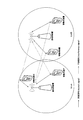
- FIG. 7 is a diagram illustrating an interference signal to a neighboring cell according to the prior art.
- mobile station apparatus 1A and mobile station apparatus 1B transmit signals to base station apparatus 3A, and signals from mobile station apparatus 1A and signals from mobile station apparatus 1B are spatially multiplexed.
- mobile station apparatus 1C and mobile station apparatus 1D transmit signals to base station apparatus 3B. At this time, both the signal of the mobile station apparatus 1A and the signal of the mobile station apparatus 1B become interference to the cell B, and both the signal of the mobile station apparatus 1C and the signal of the mobile station apparatus 1D become interference to the cell A.
- Non-Patent Document 1 describes a technique for reducing the power of a signal transmitted by a mobile station apparatus in accordance with the number of mobile station apparatuses scheduled at the same frequency in order to suppress interference with adjacent cells.
- the mobile station apparatus calculates transmission power from Equation (3) in Non-Patent Document 1.
- the base station apparatus needs to notify the mobile station apparatus of the number of mobile station apparatuses scheduled to the same frequency, and the overhead of signals from the base station apparatus to the mobile station apparatus increases. There was a problem.
- the present invention has been made in view of the above points, and its purpose is to suppress signal overhead from the base station apparatus to the mobile station apparatus in a wireless communication system in which the mobile station apparatus and the base station apparatus communicate with each other. It is another object of the present invention to provide a radio communication system, a base station apparatus, a mobile station apparatus, a radio communication method, and an integrated circuit that can efficiently control the power of a signal from the mobile station apparatus to the base station apparatus.
- the mobile station apparatus of the present invention is a mobile station apparatus that communicates with a base station apparatus, includes first transmission power control information and second transmission power control information, and is used for scheduling a physical uplink shared channel.
- the downlink control information to be used is received from the base station apparatus, the value indicated by the first transmission power control information is accumulated, and the accumulated value and the value indicated by the second transmission power control information are obtained. And the transmission power of the physical uplink shared channel is calculated.
- the mobile station apparatus of the present invention is a mobile station apparatus that communicates with a base station apparatus, and includes one transport block according to downlink control information for two transport blocks received from the base station apparatus. Transmission power control mapped to a field to which information indicating the initial transmission or retransmission of the invalid transport block is mapped. The transmission power of the physical uplink shared channel is calculated using the power offset indicated by the information.
- the present invention is characterized in that, in the above mobile station apparatus, the power offset is set to 0 when downlink control information for one transport block is received from the base station apparatus. Yes.
- the base station apparatus of this invention is a base station apparatus which communicates with a mobile station apparatus, Comprising: 1st transmission power control information and 2nd transmission power control information are included, A physical uplink shared channel
- the downlink control information used for scheduling is transmitted to the mobile station apparatus, and the value indicated by the first transmission power control information is accumulated by the mobile station apparatus, and the accumulated value and the second
- the value indicated by the transmission power control information is used by the mobile station apparatus to calculate the transmission power of the physical uplink shared channel.
- the base station apparatus of the present invention is a base station apparatus that communicates with a mobile station apparatus, and one transport block is invalidated in the mobile station apparatus by downlink control information for two transport blocks.
- transmission power control information indicating a power offset is mapped to a field to which information indicating initial transmission or retransmission of the invalid transport block is mapped. It is characterized by doing.
- wireless communications system of this invention is a radio
- the said base station apparatus is 1st transmission power control information and 2nd transmission power.
- Control information and downlink control information used for scheduling of the physical uplink shared channel is transmitted to the mobile station device, and the mobile station device receives the downlink control information control information from the base station device.
- the value indicated by the first transmission power control information is accumulated, and the transmission power of the physical uplink shared channel is calculated using the accumulated value and the value indicated by the second transmission power control information. It is characterized by that.
- the radio communication system of the present invention is a radio communication system in which a base station apparatus and a mobile station apparatus communicate with each other, and the base station apparatus uses the downlink control information for two transport blocks to When the mobile station apparatus indicates that one transport block is invalid and another transport block is valid, information indicating initial transmission or retransmission of the invalid transport block is mapped to a field to be mapped.
- Map transmission power control information indicating a power offset, transmit the downlink control information to the mobile station device, and when the mobile station device receives the downlink control information from the base station device, Using the power offset indicated by the transmission power control information, calculating the transmission power of the physical uplink shared channel It is characterized.
- the present invention provides the wireless communication system described above, wherein the mobile station apparatus indicates the validity of two transport blocks based on downlink control information for the two transport blocks received from the base station apparatus. If it is, the power offset is set to 0.
- the power offset is set to 0. It is characterized by setting.
- the radio communication method of the present invention is a radio communication method used for a mobile station apparatus communicating with a base station apparatus, and includes first transmission power control information and second transmission power control information. , Receiving downlink control information used for scheduling of a physical uplink shared channel from the base station apparatus, accumulating a value indicated by the first transmission power control information, and calculating the accumulated value and the second The transmission power of the physical uplink shared channel is calculated using the value indicated by the transmission power control information.
- a radio communication method of the present invention is a radio communication method used for a mobile station apparatus communicating with a base station apparatus, and downlink control information for two transport blocks received from the base station apparatus. Indicates that one transport block is invalid and another transport block is valid, the information indicating the initial transmission or retransmission of the invalid transport block is mapped to a field to be mapped. The transmission power of the physical uplink shared channel is calculated using a power offset indicated by mapped transmission power control information.
- the present invention is characterized in that the power offset is set to 0 when downlink control information for one transport block is received from the base station apparatus. Yes.
- the radio communication method of the present invention is a radio communication method used for a base station apparatus communicating with a mobile station apparatus, and includes first transmission power control information and second transmission power control information. , Downlink control information used for scheduling of the physical uplink shared channel is transmitted to the mobile station apparatus, and the value indicated by the first transmission power control information is accumulated by the mobile station apparatus and the accumulated And the value indicated by the second transmission power control information are used by the mobile station apparatus to calculate the transmission power of the physical uplink shared channel.
- the radio communication method of the present invention is a radio communication method used for a base station apparatus communicating with a mobile station apparatus, and 1 is assigned to the mobile station apparatus according to downlink control information for two transport blocks.
- a power offset is indicated in the field to which information indicating the initial transmission or retransmission of the invalid transport block is mapped.
- the transmission power control information is mapped.
- An integrated circuit of the present invention is an integrated circuit used in a mobile station apparatus that communicates with a base station apparatus, and includes first transmission power control information and second transmission power control information. Controls processing of the mobile station apparatus that receives downlink control information used for scheduling of an uplink shared channel from the base station apparatus, accumulates a value indicated by the first transmission power control information, and accumulates the accumulation The transmission power of the physical uplink shared channel is calculated using the calculated value and the value indicated by the second transmission power control information.
- An integrated circuit according to the present invention is an integrated circuit used in a mobile station apparatus that communicates with a base station apparatus, and is 1 based on downlink control information for two transport blocks received from the base station apparatus. If the invalidity of one transport block is indicated and the validity of another transport block is indicated, the information indicating the initial transmission or retransmission of the invalid transport block is mapped to the mapped field. The transmission power of the physical uplink shared channel is calculated using the power offset indicated by the transmission power control information.
- the present invention is characterized in that, in the above integrated circuit, the power offset is set to 0 when downlink control information for one transport block is received from the base station apparatus. .
- An integrated circuit of the present invention is an integrated circuit used in a base station apparatus that communicates with a mobile station apparatus, and includes first transmission power control information and second transmission power control information, Controls processing of the base station apparatus that transmits downlink control information used for scheduling of the uplink shared channel to the mobile station apparatus, and the value indicated by the first transmission power control information is accumulated by the mobile station apparatus. The calculated and accumulated value and the value indicated by the second transmission power control information are used by the mobile station apparatus to calculate the transmission power of the physical uplink shared channel.
- An integrated circuit according to the present invention is an integrated circuit used in a base station apparatus that communicates with a mobile station apparatus, and includes one transformer in the mobile station apparatus based on downlink control information for two transport blocks.
- the transmission power indicating the power offset is mapped to the field to which the information indicating the initial transmission or retransmission of the invalid transport block is mapped. It is characterized by mapping control information.
- the present invention in a radio communication system in which a mobile station apparatus and a base station apparatus communicate, it is possible to efficiently control signal power from the mobile station apparatus to the base station apparatus.
- FIG. 1 is a conceptual diagram of a wireless communication system according to an embodiment of the present invention. It is a table
- FIG. 1 is a conceptual diagram of a wireless communication system according to an embodiment of the present invention.
- the radio communication system includes mobile station apparatuses 1 A to 1 C and a base station apparatus 3.
- FIG. 1 shows a synchronization signal (Synchronization signal: SS), downlink reference signal (Downlink Signal: DL RS), physical broadcast channel in wireless communication (downlink) from the base station device 3 to the mobile station devices 1A to 1C.
- Physical Broadcast Channel PBCH
- Physical downlink control channel Physical Downlink ⁇ Control Channel: PDCCH
- Physical downlink shared channel Physical Downlink Shared Channel: PDSCH
- Physical multicast channel Physical Multicast Channel: PMCH
- Physical control format It indicates that an indicator channel (Physical Format Indicator Channel: PCFICH) and a physical HARQ indicator channel (Physical Hybrid ARQ ⁇ Indicator Channel: PHICH) are used.
- FIG. 1 shows an uplink reference signal (Uplink Reference Signal: UL ⁇ ⁇ RS), physical uplink control channel (Physical Uplink Control Channel) in wireless communication (uplink) from the mobile station devices 1A to 1C to the base station device 3. : PUCCH), physical uplink shared channel (Physical Uplink Shared Channel: PUSCH), physical random access channel (Physical Random Access Channel: PRACH).
- the mobile station apparatuses 1A to 1C are referred to as the mobile station apparatus 1.
- the synchronization signal is a signal used for the mobile station apparatus 1 to synchronize the downlink frequency domain and time domain.
- the downlink reference signal is used by the mobile station apparatus 1 to synchronize the downlink frequency domain and time domain, the mobile station apparatus 1 is used to measure downlink reception quality, or the mobile station This is a signal used by the device 1 to perform PDSCH or PDCCH propagation path correction.
- PBCH is a physical channel used to broadcast system information (Broadcast Channel: BCH). System information transmitted on the PBCH is referred to as Master Information Block (MIB).
- MIB Master Information Block
- the PDCCH is a physical channel used for transmitting downlink control information (Downlink Control Information: DCI) such as downlink assignment (also referred to as downlink assignment or downlink grant) and uplink grant (uplink grant).
- DCI Downlink Control Information
- the downlink assignment includes information on modulation scheme and coding rate for PDSCH (Modulation & Coding Scheme: MCS), information indicating radio resource allocation, and the like.
- MCS Modulation & Coding Scheme
- the uplink grant is composed of information on the modulation scheme and coding rate for PUSCH, information indicating radio resource allocation, and the like. A detailed configuration of the uplink grant will be described later.
- PDSCH is a physical channel used to transmit paging information (Paging Channel: PCH), system information different from system information transmitted by PBCH, and downlink data (Downlink Shared Channel: DL-SCH).
- System information transmitted on the PDSCH is referred to as System Information Block (SIB).
- the PMCH is a physical channel used for transmitting information (Multicast Channel: MCH) related to MBMS (Multimedia Broadcast and Multicast Service).
- MCH Multicast Channel
- MCH Multimedia Broadcast and Multicast Service
- PCFICH is a physical channel used for transmitting information indicating an area where a PDCCH is arranged.
- the PHICH is a physical channel used for transmitting a HARQ indicator (response information) indicating success or failure of decoding of the uplink data received by the base station apparatus 3.
- the HARQ indicator for the uplink data indicates ACK (ACKnowledgement), and the base station apparatus 3 decodes the uplink data included in the PUSCH.
- the HARQ indicator for the uplink data indicates NACK (Negative ACKnowledgement).
- a single PHICH transmits a HARQ indicator for a single uplink data.
- HARQ indicators for a plurality of uplink data included in the same PUSCH are transmitted using a plurality of PHICHs.
- the uplink reference signal is used for the base station device 3 to synchronize the uplink time domain, the base station device 3 is used to measure uplink reception quality, or the base station device 3 It is a signal used to perform propagation channel correction for PUSCH and PUCCH.
- Uplink reference signals include DMRS (Demodulation Reference Signal) transmitted time-multiplexed with PUSCH or PUCCH, and SRS (Sounding Reference Signal) transmitted regardless of PUSCH and PUCCH.
- the PUCCH is channel state information (Channel State: CSI) indicating downlink channel quality, a scheduling request (Scheduling Request: SR) indicating a request for radio resources of the PUSCH, and decoding of downlink data received by the mobile station apparatus 1.
- CSI Channel State
- SR scheduling request
- This is a physical channel used for transmitting uplink control information (Uplink Control Information: UCI), which is information used for communication control, such as ACK / NACK indicating success or failure of.
- UCI Uplink Control Information
- the PUSCH is a physical channel used for transmitting uplink data and uplink control information.
- PRACH is a physical channel used for transmitting a random access preamble.
- the PRACH is mainly used for the mobile station apparatus 1 to synchronize with the base station apparatus 3 in the time domain, and is also used for initial access, handover, reconnection request, and uplink radio resource allocation request. It is done.
- Uplink data (UL-SCH) and downlink data (DL-SCH) are transport channels.
- a unit for transmitting uplink data by PUSCH and a unit for transmitting downlink data by PDSCH are referred to as transport blocks (transport TB).
- the transport block is a unit handled in a MAC (Media Access Control) layer, and HARQ (retransmission) control is performed for each transport block.
- a unit of data handled in the MAC layer such as uplink data (UL-SCH) and downlink data (DL-SCH) is also referred to as MAC PDU (Protocol Data Unit).
- MAC PDU Protocol Data Unit
- transport blocks are mapped to code words, and encoding processing is performed for each code word.
- cell aggregation carrier aggregation
- a plurality of serving cells are aggregated.
- One serving cell among a plurality of aggregated serving cells is a primary cell (PrimaryPrimcell: Pcell).
- the primary cell is a serving cell having the same function as the LTE cell.
- the serving cell excluding the primary cell is a secondary cell (SecondScell).
- the secondary cell is a cell whose function is more limited than that of the primary cell, and is mainly used for transmission / reception of PDSCH and / or PUSCH.
- the mobile station apparatus 1 transmits PUCCH only in the primary cell.
- the mobile station device 1 does not receive paging and system information transmitted on the PBCH and PDSCH of the secondary cell.
- the carrier corresponding to the serving cell in the downlink is a downlink component carrier (Downlink Component Carrier: DL CC), and the carrier corresponding to the serving cell in the uplink is an uplink component carrier (Uplink Component Carrier: UL CCC).
- the carrier corresponding to the primary cell in the downlink is a downlink primary component carrier (Downlink Primary Component Carrier: DL PCC), and the carrier corresponding to the primary cell in the uplink is an uplink primary component carrier (Uplink Primary Component Carrier: UL PCC). ).
- the carrier corresponding to the secondary cell in the downlink is a downlink secondary component carrier (Downlink Secondary Component Carrier: DL SCC), and the carrier corresponding to the secondary cell in the uplink is an uplink secondary component carrier (Uplink Secondary Component Carrier: UL SCC). ).
- Downlink Secondary Component Carrier Downlink Secondary Component Carrier: DL SCC
- Uplink Secondary Component Carrier Uplink Secondary Component Carrier: UL SCC
- the physical channel transmitted in the serving cell has the same channel structure as LTE. Each physical channel is transmitted in any one serving cell. That is, a single physical channel is not transmitted in multiple serving cells.
- One PDSCH can be transmitted in one serving cell (DL CC), and one serving cell (UL CC) At most, one PUSCH can be transmitted.
- the downlink assignment used for the scheduling of the PDSCH of the primary cell and the uplink grant used for the scheduling of the PUSCH of the primary cell are transmitted on the PDCCH of the primary cell.
- One serving cell in which the downlink assignment used for PDSCH scheduling of the secondary cell and the uplink grant used for scheduling of the PUSCH of the secondary cell are transmitted by PDCCH is set by the base station apparatus 3 for each secondary cell.
- the base station device 3 sets, for each serving cell, whether or not the downlink assignment and the uplink grant include a carrier indicator (Carrier Indicator) that is information indicating the serving cell corresponding to the downlink assignment and the uplink grant.
- a carrier indicator Carrier Indicator
- the PHICH is transmitted in the serving cell to which the uplink grant used for scheduling of PUSCH to which the PHICH corresponds is transmitted.
- the format of the downlink control information is called a DCI format (DCIDformat).
- the DCI format of uplink grant is DCI format 0 used for scheduling of PUSCH in a single cell in single antenna port mode, and DCI format used for scheduling of PUSCH in a single cell in multi-antenna port mode. 4 is prepared.
- the mobile station apparatus 1 monitors DCI format 0 and DCI format 4 simultaneously.
- the mobile station apparatus 1 transmits PUSCH in the single antenna port mode when detecting DCI format 0, and transmits PUSCH in multi-antenna port mode when detecting DCI format 4.
- the mobile station apparatus 1 transmits a single transport block to the base station apparatus 3 using a single PUSCH in the single antenna port mode.
- the mobile station apparatus 1 transmits up to two transport blocks to the base station apparatus 3 using a single PUSCH in the multi-antenna port mode.
- the mobile station apparatus 1 transmits PUSCH using MIMO SM (Multiple Input Multiple Output Spatial Multiplexing).
- MIMO SM is a technique in which a plurality of signals are multiplexed and transmitted / received on a plurality of spatial dimension channels realized by a plurality of transmission antenna ports and a plurality of reception antenna ports.
- the antenna port indicates a logical antenna used for signal processing, and one antenna port may be configured by one physical antenna or may be configured by a plurality of physical antennas. Also good.
- a process for forming an appropriate spatial channel (referred to as precoding) is performed for a plurality of signals, and the plurality of signals subjected to the precoding process are processed. Are transmitted using a plurality of transmission antennas.
- processing for appropriately separating signals multiplexed on a spatial dimension channel from a plurality of signals received using a plurality of receiving antennas is performed.
- a plurality of fields are defined in DCI format 4, and information bits are mapped to each of the plurality of fields.
- the fields defined in DCI format 4 are listed below. Note that fields other than those listed below may be defined in the DCI format 4.
- Modulation and coding scheme and redundancy version for first transport block field A field to which an information bit indicating initial transmission or retransmission of uplink data for the first transport block is mapped (New data indicator for first transport block field) —1 bit -Modulation and coding scheme and redundancy version for second transport block field-5 bit.
- Modulation and coding scheme and redundancy version for second transport block field A field to which an information bit indicating initial transmission or retransmission of uplink data for the second transport block is mapped (New data indicator for second transport block field) —1 bit
- the number of bits [x] of the Resource block assignment field is determined according to the uplink bandwidth.
- the number of bits of Precoding information and number of layers field is 3 bits when the number of antenna ports when the mobile station apparatus 1 transmits PUSCH is 2, and the antenna when the mobile station apparatus 1 transmits PUSCH. When the number of ports is 4, it is 6 bits.
- the redundancy version indicates which part of the encoded bit sequence of the transport block the mobile station apparatus 1 transmits on the PUSCH.
- more than one physical resource block (Physical Resource Block: PRB) is indicated by Resource block assignment field, and 0 is set in modulation, and coding, scheme, and redundancy, version, for first, transport, block, and field corresponding to the transport block. Or a combination in which one physical resource block is indicated by Resource block assignment field and 28 is set in Modulation and coding scheme and redundancy version for first transport block field to which the transport block corresponds In either case, the transport block is invalid.
- the mobile station apparatus 1 determines that a transport block that is not invalid is valid.
- the mobile station device 1 does not transmit an invalid transport block (disabled transport block) on the PUSCH, but transmits an effective transport block (enabled transport block) on the PUSCH.
- the physical resource block is a unit for allocating PUSCH, and includes a frequency band (180 kHz) and a time band (0.5 msec) having a predetermined width.
- FIG. 2 is a table showing the correspondence between the New data indicator field and ⁇ power-offset for a transport block which is invalid in the present invention. If the New data indicator field for an invalid transport block is set to 0, ⁇ power-offset is ⁇ 10 log 10 (2). If the New data indicator field for an invalid transport block is set to 1, ⁇ power-offset is 0. If two transport blocks are valid in DCI format 4, or if PUSCH is scheduled in DCI format 0, ⁇ power-offset is zero.
- the base station apparatus 3 adds a cyclic redundancy check (Cyclic Redundancy Check: CRC) code generated from the downlink control information to the downlink control information.
- CRC Cyclic Redundancy Check
- the added cyclic redundancy check code is scrambled with RNTI (Radio Network Temporary Identifier).
- RNTI Radio Network Temporary Identifier
- the mobile station apparatus 1 when the mobile station apparatus 1 has its cyclic redundancy check code scrambled by C-RNTI (Cell-Radio Network Temporary Identity) assigned from the base station apparatus 3, the mobile station apparatus 1 stores the downlink control information in its own apparatus. If it is determined that the radio resource is addressed and the cyclic redundancy check code is scrambled by the SPS (Semi-Persistent-Scheduling) C-RNTI allocated from the base station apparatus 3, the downlink control information is It is determined that this indicates an allocation of a permanent (periodic) radio resource addressed to the own apparatus, a release of a permanent radio resource, or a retransmission of a PUSCH transmitted using the permanent radio resource.
- C-RNTI Cell-Radio Network Temporary Identity
- the fact that the cyclic redundancy check code scrambled by the RNTI is added to the downlink control information is simply expressed as the RNTI is included in the downlink control information or the RNTI is included in the PDCCH.
- the mobile station apparatus 1 decodes the PDCCH and the cyclic redundancy check code added to the downlink control information matches the cyclic redundancy check code generated from the downlink control information received by the mobile station apparatus 1 It is determined that the acquisition of the PDCCH is successful, and if the PDCCH is not matched, it is determined that the decoding of the PDCCH has failed. This process is called blind decoding or monitoring.
- the mobile station apparatus 1 sets the transmission power for the PUSCH based on the equation (1) or (2).
- the mobile station apparatus 1 sets the transmission power P PUSCH, c (i) for the PUSCH of the subframe i in the serving cell c. (1) Perform based on the equation.
- Mobile station apparatus 1 in the case of simultaneously transmitting the PUCCH and PUSCH in the subframe i of the serving cell c is the transmission power P PUSCH for the PUSCH subframe i of the serving cell c, setting the (2) equation of c (i) Based on.
- P CMAX, c is the maximum transmission power value set in subframe i of serving cell c
- P ′ CMAX, c is the true number of P CMAX, c
- P 'PUCCH, c is the antilog of the transmission power of the PUCCH to be transmitted in subframe i of the serving cell c.
- M PUSCH, c (i) is the PUSCH resource allocation bandwidth expressed by the number of physical resource blocks in subframe i of serving cell c.
- P O_PUSCH, c is a parameter designated from the upper layer for the serving cell c
- ⁇ c is a 3-bit parameter designated from the upper layer for the serving cell c
- ⁇ 0, 0.4, One of 0.5, 0.6, 0.7, 0.8, 0.9, 1 ⁇ is designated.
- PL c is a downlink path loss for the serving cell c measured by the mobile station device 1. The downlink path loss for the serving cell c may be measured from the primary cell.
- ⁇ TF, c (i) is an offset calculated from the resource amount and the transport block size at the time of initial transmission for the PUSCH transmitted in subframe i of serving cell c.
- f c (i) is a value calculated from a TPC command included in DCI format 0 or DCI format 4 for serving cell c.
- Mobile station apparatus 1 depending on the message of the upper layer received from the base station device 3, as a mode of calculating the f c (i), sets the first mode (accumulation mode) or the second mode (absolute) .
- Mobile station apparatus 1 that sets the first mode, the initial value of f c ( ⁇ ) and f c (0) 0, accumulating the value of the TPC command for the serving cell c to f c ( ⁇ ) .
- the mobile station apparatus 1 that has set the second mode sets the value of the TPC command for the subframe i of the serving cell c as f c (i).
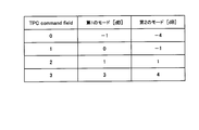
- TPC command 3 is a table showing the correspondence between TPC commands and power values according to the present invention.
- the correspondence between the TPC command and the value is different between the first mode and the second mode.
- the TPC command indicates one value of ⁇ -1, 0, 1, 3 ⁇ .
- the TPC command indicates one value of ⁇ -4, -1, 1, 4 ⁇ .
- ⁇ power-offset (i) is a value that is explicitly or implicitly indicated by DCI format 0 or DCI format 4 for the serving cell c. If the New data indicator field for an invalid transport block is set to 0, ⁇ power-offset is ⁇ 10 log 10 (2). If the New data indicator field for an invalid transport block is set to 1, ⁇ power-offset is 0. If two transport blocks are valid in DCI format 4, or if PUSCH is scheduled in DCI format 0, ⁇ power-offset is zero. When the mobile station apparatus 1 does not receive the DCI format 0 and the DCI format 4 in the subframe i and receives a NACK in PHICH for the transport block, the mobile station apparatus 1 receives the DCI format 0 last received for the transport block. Alternatively , the value of ⁇ power-offset is determined according to DCI format 4.
- the mobile station apparatus 1 transmits a power headroom (PH) for each serving cell to the base station apparatus 3.
- PH power headroom
- the mobile station apparatus 1 sets the power headroom PH type1, c (i) for the PUSCH of the subframe i of the serving cell c to ( 3) Calculate from the equation.
- the mobile station apparatus 1 calculates the power headroom PH type1, c (i) for the PUSCH of the subframe i of the serving cell c from Equation (4). To do.
- P ′′ CMAX, c is the maximum transmission power value set not to take backoff in subframe i of serving cell c.
- FIG. 4 is a schematic block diagram showing the configuration of the base station apparatus 3 of the present invention.
- the base station apparatus 3 includes an upper layer processing unit 301, a control unit 303, a reception unit 305, a transmission unit 307, and a transmission / reception antenna 309.
- the upper layer processing unit 301 includes a radio resource control unit 3011, a scheduling unit 3013, and a control information generation unit 3015.
- the reception unit 305 includes a decoding unit 3051, a demodulation unit 3053, a demultiplexing unit 3055, a wireless reception unit 3057, and a channel measurement unit 3059.
- the transmission unit 307 includes an encoding unit 3071, a modulation unit 3073, a multiplexing unit 3075, a radio transmission unit 3077, and a downlink reference signal generation unit 3079.
- the upper layer processing unit 301 includes a medium access control (MAC: Medium Access Control) layer, a packet data integration protocol (Packet Data Convergence Protocol: PDCP) layer, a radio link control (Radio Link Control: RLC) layer, a radio resource control (Radio). Resource (Control: RRC) layer processing.
- MAC Medium Access Control
- PDCP Packet Data Convergence Protocol
- RLC Radio Link Control
- Radio Radio Resource Control
- Control Control: RRC
- the radio resource control unit 3011 provided in the upper layer processing unit 301 generates downlink data (transport block), RRC signal, MAC CE (Control Element) arranged in the downlink PDSCH, or acquires it from the upper node. And output to the transmission unit 307. Further, the radio resource control unit 3011 manages various setting information of each mobile station apparatus 1. For example, the radio resource control unit 3011 performs management of the mode of the TPC command, management of the serving cell set in the mobile station apparatus 1 and the like.
- the scheduling unit 3013 included in the higher layer processing unit 301 performs PDSCH and PUSCH scheduling, and notifies the control information generation unit 3015 of the scheduling result.
- Scheduling section 3013 determines a pair of mobile station apparatuses 1 that perform MU-MIMO, and notifies downlink control information generation section 3015 of the pair of mobile station apparatuses 1 that perform MU-MIMO.
- the scheduling unit 3013 determines a parameter related to uplink transmission power, and notifies the determined parameter to the control information generation unit 3015.
- a control information generation unit 3015 included in the higher layer processing unit 301 generates downlink control information transmitted on the PDCCH based on the scheduling result notified from the scheduling unit 3013.
- the control information generation unit 3015 has a DCI format indicating that one transport block is invalid and ⁇ power-offset is ⁇ 10 log 10 (2) for the mobile station apparatus 1 performing MU-MIMO notified from the scheduling unit 3013. 4 is generated.
- the control information generation unit 3015 generates information indicating the parameter based on the parameter regarding the uplink transmission power notified from the scheduling unit 3013.
- the control unit 303 generates a control signal for controlling the reception unit 305 and the transmission unit 307 based on the control information from the higher layer processing unit 301.
- the control unit 303 outputs the generated control signal to the reception unit 305 and the transmission unit 307 and controls the reception unit 305 and the transmission unit 307.
- the reception unit 305 separates, demodulates, decodes, and decodes the PUCCH, PUSCH, PRACH, and uplink reference signal received from the mobile station apparatus 1 via the transmission / reception antenna 309 according to the control signal input from the control unit 303 The information is output to the upper layer processing unit 301.
- the receiving unit 305 measures the state of the uplink channel from the received uplink signal and outputs the measurement result to the higher layer processing unit 301.
- the transmission unit 307 generates a downlink reference signal according to the control signal input from the control unit 303, encodes and modulates the HARQ indicator, downlink control information, and downlink data input from the higher layer processing unit 301. Then, the PHICH, PDCCH, PDSCH, and downlink reference signal are multiplexed, and the signal is transmitted to the mobile station device 1 via the transmission / reception antenna 309.
- FIG. 5 is a schematic block diagram showing the configuration of the mobile station apparatus 1 of the present invention.
- the mobile station apparatus 1 includes an upper layer processing unit 101, a control unit 103, a receiving unit 105, a transmitting unit 107, and a transmission / reception antenna 109.
- the upper layer processing unit 101 includes a radio resource control unit 1011, a scheduling unit 1013, and a transmission power control unit 1015.
- the reception unit 105 includes a decoding unit 1051, a demodulation unit 1053, a demultiplexing unit 1055, a radio reception unit 1057, and a channel measurement unit 1059.
- the transmission unit 107 includes an encoding unit 1071, a modulation unit 1073, a multiplexing unit 1075, a radio transmission unit 1077, and an uplink reference signal generation unit 1079.
- the upper layer processing unit 101 outputs uplink data generated by a user operation or the like to the transmission unit 107.
- the upper layer processing unit 101 includes a medium access control (MAC: Medium Access Control) layer, a packet data integration protocol (Packet Data Convergence Protocol: PDCP) layer, a radio link control (Radio Link Control: RLC) layer, and radio resource control. Process the (Radio Resource Control: RRC) layer.
- MAC Medium Access Control
- PDCP Packet Data Convergence Protocol
- RLC Radio Link Control
- RRC Radio Resource Control
- upper layer processing section 101 generates control information for controlling receiving section 105 and transmitting section 107 and outputs the control information to control section 103. *
- the radio resource control unit 1011 included in the upper layer processing unit 101 manages various setting information of the own device. For example, the radio resource control unit 1011 manages the TPC command mode and the serving cell. The radio resource control unit 1011 generates information arranged in each uplink channel and outputs the information to the transmission unit 107.
- the scheduling unit 1013 included in the higher layer processing unit 101 controls the receiving unit 105 via the control unit 103 so as to receive the PDSCH according to the downlink assignment input from the receiving unit 105.
- the scheduling unit 1013 controls the transmission unit 107 via the control unit 103 so as to transmit the PUSCH according to the uplink grant input from the reception unit 105.
- the scheduling unit 1013 outputs the TPC command included in the uplink grant to the transmission power control unit 1015.
- the scheduling unit 1013 confirms that ⁇ power-offset is 0 when the last received DCI format for the PUSCH is DCI format 0 or DCI format 4 in which two transport blocks are valid.
- the transmission power control unit 1015 is notified.
- the scheduling unit 1013 uses the value set in the New data indicator field for the invalid transport block.
- the transmission power control unit 1015 is notified of the determined ⁇ power-offset .
- the control unit 103 generates a control signal for controlling the receiving unit 105 and the transmitting unit 107 based on the control information from the higher layer processing unit 101. Control unit 103 outputs the generated control signal to receiving unit 105 and transmitting unit 107 to control receiving unit 105 and transmitting unit 107.
- the receiving unit 105 separates, demodulates, decodes, and decodes the PHICH, PDCCH, PDSCH, and downlink reference signal received from the base station apparatus 3 via the transmission / reception antenna 109 according to the control signal input from the control unit 103.
- the information is output to the upper layer processing unit 101.
- the receiving unit 105 measures the state of the uplink channel from the received downlink signal, and outputs the measurement result to the higher layer processing unit 101.
- the transmission unit 107 generates an uplink reference signal according to the control signal input from the control unit 103, encodes and modulates the uplink data (transport block) input from the higher layer processing unit 101, PUCCH, The PUSCH and the generated uplink reference signal are multiplexed and transmitted to the base station apparatus 3 via the transmission / reception antenna 109.
- FIG. 6 is a flowchart showing an example of the operation of the mobile station apparatus 1 of the present invention.
- the mobile station apparatus 1 sets the upper layer parameter regarding the transmission power control received from the base station apparatus 3 (step S100).
- the mobile station apparatus 1 receives the upper layer signal indicating the TPC command mode from the base station apparatus 3, and sets the TPC command mode according to the received upper layer signal (step S102).
- the mobile station apparatus 1 sets the TPC command mode to the default mode.
- the default mode is a predetermined mode and may be the first mode or the second mode.
- the mobile station apparatus 1 receives the uplink grant (DCI format 0 or DCI format 4) used for PUSCH scheduling (step S102).
- the mobile station apparatus 1 is invalid if the last received uplink grant is DCI format 4 (step S103-DCI format 4) and one transport block is invalid (step S104-Yes).
- ⁇ power-offset is determined from the value set in the New data indicator field for the transport block (step S105).
- Step S105-0 When 0 is set in the New data indicator field in Step S105 (Step S105-0), the mobile station apparatus 1 sets ⁇ power-offset to ⁇ 10 log 10 (2) (Step S106). If 1 is set in the New data indicator field in Step S105 (Step S105-1), the mobile station apparatus 1 sets ⁇ power-offset to 0 (Step S107).
- step S103 When the uplink grant last received in step S103 is DCI format 0 (step S103-DCI format 0), the mobile station apparatus 1 sets ⁇ power-offset to 0 (step S107). When the two transport blocks are valid in step S104 (step S104-No), the mobile station device 1 sets ⁇ power-offset to 0 (step S107).
- the mobile station apparatus 1 determines the mode of the TPC command set in step S101 after step S106 or step S107 (step S108).
- the mode of the TPC command is the second mode (absolute) (step S108—second mode)
- the mobile station device 1 sets the value of the TPC command to f c (i). (Step S110).
- the mobile station apparatus 1 calculates the PUSCH transmission power from the equation (1) or (2) after step S109 or step S110 (step S111).
- the base station apparatus 3 uses the TPC command (first transmission power control information) and the ⁇ power-offset. And transmits DCI format 4 (downlink control information) used for scheduling of PUSCH (physical uplink shared channel) to the mobile station apparatus 1.
- DCI format 4 downlink control information
- PUSCH physical uplink shared channel
- 1 receives the DCI format 4 from the base station apparatus 3, accumulates the value indicated by the TPC command (first transmission power control information), and uses the accumulated value and the value of ⁇ power-offset. Then, the transmission power of PUSCH is calculated. Thereby, it is possible to accurately control the transmission power of PUSCH.
- the base station apparatus 3 moves according to the DCI format 4 (downlink control information for two transport blocks).
- DCI format 4 downlink control information for two transport blocks.
- the station apparatus 1 indicates that one transport block is invalid and another transport block is valid, a new data indicator field (information indicating initial transmission or retransmission) of the invalid transport block is displayed.
- the transmission power control information indicating ⁇ power-offset (power offset) is mapped to the mapped field), and the DCI format 4 is transmitted to the mobile station apparatus 1.
- the mobile station apparatus 1 bases the DCI format 4 on the base
- the transmission power of PUSCH is calculated using ⁇ power-offset indicated by the transmission power control information. To do.
- the base station apparatus 3 can re-use the New data indicator field of the invalid transport block and notify the mobile station apparatus 1 of ⁇ power-offset.
- the power of the signal to the station device can be controlled.
- a program that operates in the base station apparatus 3 and the mobile station apparatus 1 related to the present invention is a program (computer functions as a computer) that controls a CPU (Central Processing Unit) so as to realize the functions of the above-described embodiments related to the present invention Program).
- Information handled by these devices is temporarily stored in RAM (Random Access Memory) during the processing, and then stored in various ROMs such as Flash ROM (Read Only Memory) and HDD (Hard Disk Drive). Reading, correction, and writing are performed by the CPU as necessary.
- the program for realizing the control function may be recorded on a computer-readable recording medium, and the program recorded on the recording medium may be read by the computer system and executed.
- the “computer system” here is a computer system built in the mobile station apparatus 1 or the base station apparatus 3, and includes an OS and hardware such as peripheral devices.
- the “computer-readable recording medium” refers to a storage device such as a flexible medium, a magneto-optical disk, a portable medium such as a ROM or a CD-ROM, and a hard disk incorporated in a computer system.
- the “computer-readable recording medium” is a medium that dynamically holds a program for a short time, such as a communication line when transmitting a program via a network such as the Internet or a communication line such as a telephone line,
- a volatile memory inside a computer system serving as a server or a client may be included and a program that holds a program for a certain period of time.
- the program may be a program for realizing a part of the functions described above, and may be a program capable of realizing the functions described above in combination with a program already recorded in a computer system.
- a part or all of the mobile station device 1 and the base station device 3 in the above-described embodiment may be realized as an LSI that is typically an integrated circuit, or may be realized as a chip set.
- Each functional block of the mobile station device 1 and the base station device 3 may be individually chipped, or a part or all of them may be integrated into a chip.
- the method of circuit integration is not limited to LSI, and may be realized by a dedicated circuit or a general-purpose processor.
- an integrated circuit based on the technology can also be used.
Landscapes
- Engineering & Computer Science (AREA)
- Signal Processing (AREA)
- Computer Networks & Wireless Communication (AREA)
- Mobile Radio Communication Systems (AREA)
Abstract
La puissance d'un signal émis par un dispositif de communication mobile à destination d'un dispositif terminal de base est commandée efficacement dans un système de communication sans fil dans lequel un dispositif terminal mobile et un dispositif terminal de base sont en communication. Une unité de planification (1013) communique à une unité de commande de puissance d'émission (1015) que δdécalage-puissance est à 0 lorsque le dernier format DCI reçu d'un PUSCH est le format DCI 0, ou le format DCI 4 dans lequel deux blocs de transport ont un effet. L'unité de planification (1013) amène un δdécalage-puissance, déterminé d'après une valeur appliquée à un champ d'indicateur de nouvelles données en rapport à un bloc de transport sans effet, à communiquer à l'unité de commande de puissance d'émission (1015), lorsque le dernier format DCI reçu du PUSCH est le format DCI 4 dans lequel un bloc de transport est sans effet.
Priority Applications (1)
| Application Number | Priority Date | Filing Date | Title |
|---|---|---|---|
| US14/116,463 US9191902B2 (en) | 2011-05-10 | 2012-04-04 | Radio communication system, base station device, mobile station device, radio communication method, and integrated circuit |
Applications Claiming Priority (2)
| Application Number | Priority Date | Filing Date | Title |
|---|---|---|---|
| JP2011-104910 | 2011-05-10 | ||
| JP2011104910A JP5739221B2 (ja) | 2011-05-10 | 2011-05-10 | 基地局装置、移動局装置、無線通信方法および集積回路 |
Publications (1)
| Publication Number | Publication Date |
|---|---|
| WO2012153580A1 true WO2012153580A1 (fr) | 2012-11-15 |
Family
ID=47139066
Family Applications (1)
| Application Number | Title | Priority Date | Filing Date |
|---|---|---|---|
| PCT/JP2012/059140 Ceased WO2012153580A1 (fr) | 2011-05-10 | 2012-04-04 | Système de communication sans fil, dispositif terminal de base, dispositif terminal mobile, procédé de communication sans fil et circuit intégré |
Country Status (3)
| Country | Link |
|---|---|
| US (1) | US9191902B2 (fr) |
| JP (1) | JP5739221B2 (fr) |
| WO (1) | WO2012153580A1 (fr) |
Cited By (3)
| Publication number | Priority date | Publication date | Assignee | Title |
|---|---|---|---|---|
| CN106465365A (zh) * | 2014-03-28 | 2017-02-22 | 华为技术有限公司 | 多用户、多址接入系统、方法及设备 |
| CN109804698A (zh) * | 2016-08-10 | 2019-05-24 | 瑞典爱立信有限公司 | 争用信道的数据传输技术 |
| EP3962184A1 (fr) * | 2013-03-18 | 2022-03-02 | Samsung Electronics Co., Ltd. | Commande de puissance de liaison montante dans des systèmes de communication tdd configurés de manière adaptative |
Families Citing this family (9)
| Publication number | Priority date | Publication date | Assignee | Title |
|---|---|---|---|---|
| US8014264B2 (en) | 2004-05-01 | 2011-09-06 | Neocific, Inc. | Methods and apparatus for communication with time-division duplexing |
| JP5009410B2 (ja) * | 2010-10-29 | 2012-08-22 | シャープ株式会社 | 移動局装置、無線通信方法および集積回路 |
| US9955467B2 (en) * | 2013-06-27 | 2018-04-24 | Telefonaktiebolaget L M Ericsson (Publ) | Method and BS for transmitting control information to UE, and method and UE for handling control information |
| WO2015005334A1 (fr) * | 2013-07-09 | 2015-01-15 | シャープ株式会社 | Appareil terminal, appareil station de base, méthode de communication, et circuit intégré |
| CN105340337B (zh) * | 2013-07-09 | 2020-02-04 | 夏普株式会社 | 终端装置、基站装置以及通信方法 |
| WO2016208350A1 (fr) * | 2015-06-26 | 2016-12-29 | 京セラ株式会社 | Station de base et terminal sans fil |
| CN113660728B (zh) | 2016-02-05 | 2024-05-07 | 松下电器(美国)知识产权公司 | 基站、终端和通信方法 |
| JP6849062B2 (ja) * | 2017-06-15 | 2021-03-24 | 富士通株式会社 | 基地局装置、端末装置、無線通信システム及び通信方法 |
| EP3700109B1 (fr) | 2019-02-21 | 2024-01-10 | Volkswagen Aktiengesellschaft | Véhicule, système, appareils, procédés et programmes informatiques pour un équipement utilisateur et composant de réseau d'un système de communication mobile |
Citations (3)
| Publication number | Priority date | Publication date | Assignee | Title |
|---|---|---|---|---|
| JP2010034612A (ja) * | 2008-06-23 | 2010-02-12 | Ntt Docomo Inc | 移動通信方法、移動局及び無線基地局 |
| WO2010104006A1 (fr) * | 2009-03-10 | 2010-09-16 | シャープ株式会社 | Dispositif de station mobile, système de communications, procédé de communications et programme |
| WO2010146972A1 (fr) * | 2009-06-16 | 2010-12-23 | シャープ株式会社 | Dispositif de station mobile, dispositif de station de base, procédé de radiocommunications, et logiciel de communication |
Family Cites Families (6)
| Publication number | Priority date | Publication date | Assignee | Title |
|---|---|---|---|---|
| CN101567713B (zh) * | 2008-04-25 | 2012-10-03 | 电信科学技术研究院 | 时分双工系统中上行传输功率的确定方法、系统及装置 |
| TWI508590B (zh) * | 2009-02-09 | 2015-11-11 | Interdigital Patent Holdings | 利用多載波無線傳送器/接收器單元之上鏈功率控制裝置及方法 |
| KR101225928B1 (ko) * | 2009-09-08 | 2013-01-24 | 엘지전자 주식회사 | 무선 통신 시스템에서 전송 파워 제어 방법 및 장치 |
| WO2011078631A2 (fr) * | 2009-12-27 | 2011-06-30 | 엘지전자 주식회사 | Procédé et appareil pour commander la puissance de transmission de liaison montante dans un système de communication sans fil à porteuses multiples |
| US8965442B2 (en) * | 2010-05-07 | 2015-02-24 | Qualcomm Incorporated | Uplink power control in aggregated carrier communication systems |
| US8744513B2 (en) * | 2010-06-29 | 2014-06-03 | Qualcomm Incorporated | Interaction between maximum power reduction and power scaling in wireless networks |
-
2011
- 2011-05-10 JP JP2011104910A patent/JP5739221B2/ja not_active Expired - Fee Related
-
2012
- 2012-04-04 WO PCT/JP2012/059140 patent/WO2012153580A1/fr not_active Ceased
- 2012-04-04 US US14/116,463 patent/US9191902B2/en not_active Expired - Fee Related
Patent Citations (3)
| Publication number | Priority date | Publication date | Assignee | Title |
|---|---|---|---|---|
| JP2010034612A (ja) * | 2008-06-23 | 2010-02-12 | Ntt Docomo Inc | 移動通信方法、移動局及び無線基地局 |
| WO2010104006A1 (fr) * | 2009-03-10 | 2010-09-16 | シャープ株式会社 | Dispositif de station mobile, système de communications, procédé de communications et programme |
| WO2010146972A1 (fr) * | 2009-06-16 | 2010-12-23 | シャープ株式会社 | Dispositif de station mobile, dispositif de station de base, procédé de radiocommunications, et logiciel de communication |
Non-Patent Citations (1)
| Title |
|---|
| 3GPP TS 36.213 V10.1.0, March 2011 (2011-03-01), pages 9 - 18 * |
Cited By (4)
| Publication number | Priority date | Publication date | Assignee | Title |
|---|---|---|---|---|
| EP3962184A1 (fr) * | 2013-03-18 | 2022-03-02 | Samsung Electronics Co., Ltd. | Commande de puissance de liaison montante dans des systèmes de communication tdd configurés de manière adaptative |
| CN106465365A (zh) * | 2014-03-28 | 2017-02-22 | 华为技术有限公司 | 多用户、多址接入系统、方法及设备 |
| CN109804698A (zh) * | 2016-08-10 | 2019-05-24 | 瑞典爱立信有限公司 | 争用信道的数据传输技术 |
| CN109804698B (zh) * | 2016-08-10 | 2023-07-25 | 瑞典爱立信有限公司 | 争用信道的数据传输方法、介质及装置 |
Also Published As
| Publication number | Publication date |
|---|---|
| JP2012238937A (ja) | 2012-12-06 |
| US9191902B2 (en) | 2015-11-17 |
| JP5739221B2 (ja) | 2015-06-24 |
| US20140198743A1 (en) | 2014-07-17 |
Similar Documents
| Publication | Publication Date | Title |
|---|---|---|
| JP5739221B2 (ja) | 基地局装置、移動局装置、無線通信方法および集積回路 | |
| JP5331161B2 (ja) | 無線通信システム、基地局装置、移動局装置、無線通信方法および集積回路 | |
| CN105359594B (zh) | 终端装置、方法以及集成电路 | |
| TWI594649B (zh) | 用於上行鏈路功率控制之方法及配置 | |
| JP6376564B2 (ja) | 端末装置、基地局装置、通信方法および集積回路 | |
| JP6439192B2 (ja) | 端末装置、基地局装置、集積回路、および、無線通信方法 | |
| JP6400023B2 (ja) | 端末装置、基地局装置、および、通信方法 | |
| JP6400022B2 (ja) | 端末装置、基地局装置、および、通信方法 | |
| JP6260031B2 (ja) | ユーザ装置、基地局装置、集積回路、および、通信方法 | |
| WO2015111325A1 (fr) | Dispositif d'utilisateur, dispositif de station de base, circuit intégré et procédé de communication | |
| JP6362114B2 (ja) | 端末装置、基地局装置、および通信方法 | |
| WO2015005325A1 (fr) | Appareil terminal, appareil station de base, procédé de communication et circuit intégré | |
| WO2015005334A1 (fr) | Appareil terminal, appareil station de base, méthode de communication, et circuit intégré | |
| WO2017195659A1 (fr) | Dispositif terminal, dispositif station de base, procédé de communication et circuit intégré | |
| WO2015159877A1 (fr) | Dispositif de terminal, dispositif de station de base, circuit intégré et procédé de communication | |
| WO2017022617A1 (fr) | Dispositif terminal, dispositif station de base, procédé de communication, et circuit intégré | |
| WO2016163186A1 (fr) | Appareil terminal, appareil de station de base, circuit intégré et procédé de communication | |
| WO2012153582A1 (fr) | Système de communication sans fil, dispositif terminal de base, dispositif terminal mobile, procédé de communication sans fil et circuit intégré | |
| JP6385348B2 (ja) | 端末装置、基地局装置、集積回路、および、通信方法 | |
| WO2017002804A1 (fr) | Dispositif terminal, station de base, procédé de communication, et circuit intégré | |
| JP2015204514A (ja) | 端末装置、および、基地局装置 | |
| JP6037963B2 (ja) | 基地局装置、移動局装置、無線通信方法および集積回路 | |
| JP5833862B2 (ja) | 移動局装置、基地局装置、無線通信方法、無線通信システムおよび集積回路 |
Legal Events
| Date | Code | Title | Description |
|---|---|---|---|
| 121 | Ep: the epo has been informed by wipo that ep was designated in this application |
Ref document number: 12781972 Country of ref document: EP Kind code of ref document: A1 |
|
| DPE2 | Request for preliminary examination filed before expiration of 19th month from priority date (pct application filed from 20040101) | ||
| NENP | Non-entry into the national phase |
Ref country code: DE |
|
| WWE | Wipo information: entry into national phase |
Ref document number: 14116463 Country of ref document: US |
|
| 122 | Ep: pct application non-entry in european phase |
Ref document number: 12781972 Country of ref document: EP Kind code of ref document: A1 |