WO2012153592A1 - Joint universel homocinétique - Google Patents
Joint universel homocinétique Download PDFInfo
- Publication number
- WO2012153592A1 WO2012153592A1 PCT/JP2012/059785 JP2012059785W WO2012153592A1 WO 2012153592 A1 WO2012153592 A1 WO 2012153592A1 JP 2012059785 W JP2012059785 W JP 2012059785W WO 2012153592 A1 WO2012153592 A1 WO 2012153592A1
- Authority
- WO
- WIPO (PCT)
- Prior art keywords
- joint member
- velocity universal
- constant velocity
- universal joint
- bellows
- Prior art date
- Legal status (The legal status is an assumption and is not a legal conclusion. Google has not performed a legal analysis and makes no representation as to the accuracy of the status listed.)
- Ceased
Links
Images


Classifications
-
- F—MECHANICAL ENGINEERING; LIGHTING; HEATING; WEAPONS; BLASTING
- F16—ENGINEERING ELEMENTS AND UNITS; GENERAL MEASURES FOR PRODUCING AND MAINTAINING EFFECTIVE FUNCTIONING OF MACHINES OR INSTALLATIONS; THERMAL INSULATION IN GENERAL
- F16D—COUPLINGS FOR TRANSMITTING ROTATION; CLUTCHES; BRAKES
- F16D3/00—Yielding couplings, i.e. with means permitting movement between the connected parts during the drive
- F16D3/84—Shrouds, e.g. casings, covers; Sealing means specially adapted therefor
- F16D3/843—Shrouds, e.g. casings, covers; Sealing means specially adapted therefor enclosed covers
- F16D3/845—Shrouds, e.g. casings, covers; Sealing means specially adapted therefor enclosed covers allowing relative movement of joint parts due to the flexing of the cover
-
- F—MECHANICAL ENGINEERING; LIGHTING; HEATING; WEAPONS; BLASTING
- F16—ENGINEERING ELEMENTS AND UNITS; GENERAL MEASURES FOR PRODUCING AND MAINTAINING EFFECTIVE FUNCTIONING OF MACHINES OR INSTALLATIONS; THERMAL INSULATION IN GENERAL
- F16D—COUPLINGS FOR TRANSMITTING ROTATION; CLUTCHES; BRAKES
- F16D3/00—Yielding couplings, i.e. with means permitting movement between the connected parts during the drive
- F16D3/16—Universal joints in which flexibility is produced by means of pivots or sliding or rolling connecting parts
- F16D3/20—Universal joints in which flexibility is produced by means of pivots or sliding or rolling connecting parts one coupling part entering a sleeve of the other coupling part and connected thereto by sliding or rolling members
- F16D3/22—Universal joints in which flexibility is produced by means of pivots or sliding or rolling connecting parts one coupling part entering a sleeve of the other coupling part and connected thereto by sliding or rolling members the rolling members being balls, rollers, or the like, guided in grooves or sockets in both coupling parts
- F16D3/223—Universal joints in which flexibility is produced by means of pivots or sliding or rolling connecting parts one coupling part entering a sleeve of the other coupling part and connected thereto by sliding or rolling members the rolling members being balls, rollers, or the like, guided in grooves or sockets in both coupling parts the rolling members being guided in grooves in both coupling parts
- F16D3/2237—Universal joints in which flexibility is produced by means of pivots or sliding or rolling connecting parts one coupling part entering a sleeve of the other coupling part and connected thereto by sliding or rolling members the rolling members being balls, rollers, or the like, guided in grooves or sockets in both coupling parts the rolling members being guided in grooves in both coupling parts where the grooves are composed of radii and adjoining straight lines, i.e. undercut free [UF] type joints
Definitions
- the present invention is suitable for, for example, a fixed type constant velocity universal joint incorporated in a drive shaft of an automobile, particularly a front wheel drive shaft, and includes a boot that prevents foreign matter from entering from the outside of the joint and lubricant leakage from the inside of the joint. It relates to a constant velocity universal joint.
- constant velocity universal joints that are used as means for transmitting rotational force from an automobile engine to wheels at a constant speed: a fixed constant velocity universal joint and a sliding constant velocity universal joint. Both of these constant velocity universal joints have a structure in which two shafts on the driving side and the driven side are connected so that rotational torque can be transmitted at a constant speed even if the two shafts have an operating angle.
- the drive shaft that transmits power from the engine of the automobile to the driving wheel needs to correspond to the angular displacement and axial displacement due to the change in the relative positional relationship between the engine and the wheel, the engine side (inboard side) ) And a fixed type constant velocity universal joint on the drive wheel side (outboard side), and both constant velocity universal joints are connected by an intermediate shaft.
- the boot has a large-diameter end fastened to the outer peripheral surface of the opening of the outer joint member, a small-diameter end fastened to the outer peripheral surface of the intermediate shaft extending from the inner joint member, a large-diameter end, and a small-diameter end. And a bellows portion having a diameter reduced from the large diameter end portion toward the small diameter end portion. Since this constant velocity universal joint has a function of rotating while taking an operating angle, this boot has a bellows shape that can be expanded and contracted in order to ensure flexibility that can follow its behavior (see, for example, Patent Document 1). ).
- the bellows-shaped boot disclosed in Patent Document 1 described above has a uniform annular shape on at least one of two annular side surfaces of at least one of the plurality of annular folds.
- the structure has a plurality of raised portions protruding from the side surface or a plurality of recessed portions recessed.
- the opposed annular side surfaces of two adjacent annular folds are held at positions separated from each other by the ridges, and are not rubbed against each other on a plane by the recesses. It is designed to reduce the generation of noise, especially under wet rain conditions.
- the present invention has been proposed in view of the above-described problems, and the object of the present invention is to reliably eliminate the scratching noise generated by the contact between the bellows portions when rotating with the operating angle taken.
- An object of the present invention is to provide a constant velocity universal joint that can be suppressed.
- the present invention provides torque while allowing angular displacement between an outer joint member having an opening at one end and a torque transmission member between the outer joint member.
- a constant velocity universal joint comprising: an inner joint member for transmission; and an end portion of the bellows-like boot that closes the opening of the outer joint member fastened and fixed to the opening of the outer joint member and a shaft member extending from the inner joint member.
- the boot connects the large-diameter end fastened to the outer peripheral surface of the opening of the outer joint member and the small-diameter end fastened and fixed to the outer peripheral surface of the shaft member, and connects the large-diameter end to the small-diameter end.
- the boot of the present invention is preferably made of a resin made of a thermoplastic polyester elastomer.
- “at least a pair of adjacent slopes of the bellows portion” includes all adjacent slopes such as two pairs of adjacent slopes and three pairs of adjacent slopes in addition to the pair of adjacent slopes. Means.
- the boot rotates while deforming with the outer joint member and the inner joint member taking an operating angle.
- the grid-like convex portions provided on both the adjacent slopes come into contact with each other, and the contact area can be greatly reduced. . Therefore, it is possible to reliably suppress the rubbing sound that occurs when the inclined surfaces of the bellows portions come into contact with each other, and it is possible to ensure a long duration in which the rubbing sound does not occur.
- the bellows portion according to the present invention has a pair of slopes or a small diameter end portion in which five peak portions are formed along the joint axial direction and connects the second peak portion and the third peak portion from the small diameter end portion. It is preferable that at least one of the pair of slopes connecting the third peak and the fourth peak is provided with a grid-like convex part.
- the bellows part in which the five peak parts are formed along the joint axial direction the second peak part, the third peak part, and the fourth peak part 4 from the small diameter end part when rotating with the operating angle taken. Since the first ridge is greatly deformed, a pair of slopes connecting these ridges are likely to come into contact with each other and cause relative movement (stick-slip). In addition, it is possible to further reliably suppress the rubbing sound generated by the contact between the inclined surfaces of the bellows portions, and to ensure a long duration in which the rubbing sound does not occur.
- a pair of slopes connecting the second peak and the third peak from the end of the small diameter, or connecting the third peak and the fourth peak from the end of the small diameter At least one of the pair of slopes” means that when a grid-like convex portion is provided only on a pair of slopes connecting the second peak and the third peak from the small diameter end, When providing a grid-like convex part only on a pair of slopes connecting the first peak and the fourth peak, a pair connecting the second peak and the third peak from the small diameter end This includes the case where a grid-like convex portion is provided on both of the slope and the pair of slopes connecting the third peak and the fourth peak from the small-diameter end.
- the convex portions in the present invention are preferably formed so as to extend in a lattice shape with an inclination angle with respect to the joint axial direction.
- the convex portions in the present invention are preferably formed in a lattice shape with adjacent intervals of 2 mm or more and 6 mm or less. If it does in this way, the rubbing sound which generate
- the interval between adjacent protrusions is smaller than 2 mm, the lattice shape becomes too fine, and it becomes difficult to obtain the effect of suppressing the scratching sound.
- the convex portion in the present invention is preferably formed at a height of 0.2 mm to 0.6 mm from the slope. If it does in this way, the rubbing sound which generate
- the height of the convex part is smaller than 0.2 mm, when the slopes adjacent to the bellows part are close to each other with an operating angle, the slopes that are concave parts other than the convex part come into contact with the adjacent slopes. Therefore, it becomes difficult to obtain the effect of suppressing the scratching sound.
- the height of the convex portion is larger than 0.6 mm, the boot formability and the moldability are lowered.
- the convex portion in the present invention is preferably formed such that the tip width dimension in contact with the adjacent slope is 1/3 or less of the adjacent interval. If it does in this way, the rubbing sound which generate
- the tip width dimension of the convex part that contacts the adjacent slope is larger than 1/3 of the adjacent interval, the total contact area of the convex part tip that contacts the adjacent slope becomes large, so the effect of suppressing fretting noise is obtained. It becomes difficult to obtain.
- the present invention relates to an outer joint member in which a plurality of arc-shaped track grooves extending in the axial direction are formed on a spherical inner peripheral surface, and a plurality of arc-shaped members on a spherical outer peripheral surface in pairs with the track grooves of the outer joint member.
- the track groove of the outer joint member is held by a cage disposed between the inner joint member formed with the track groove and the spherical inner peripheral surface of the outer joint member and the spherical outer peripheral surface of the inner joint member.
- the boot rotates while the outer joint member and the inner joint member take an operating angle.
- the grid-like convex portions provided on both adjacent slopes come into contact with each other, and the contact area is greatly reduced. Can do. Therefore, it is possible to reliably suppress the rubbing sound that occurs when the inclined surfaces of the bellows portions come into contact with each other, and it is possible to ensure a long duration in which the rubbing sound does not occur.
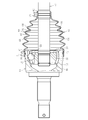
- it is a front view which shows the constant velocity universal joint of the state which mounted
- it is an expanded sectional view which illustrates the shape of a lattice-like convex part.
- it is an expanded sectional view which illustrates the shape of a lattice-like convex part.
- it is an expanded sectional view which illustrates the shape of a lattice-like convex part.
- it is an expanded sectional view which illustrates the height in a grid
- a fixed constant velocity is provided that is incorporated in a drive shaft of an automobile and has a structure in which two shafts on a driving side and a driven side are connected to transmit rotational torque at a constant speed even when the two shafts have an operating angle.
- An undercut-free constant velocity universal joint which is one of universal joints, will be exemplified.
- the present invention can also be applied to other fixed type constant velocity universal joints such as a Rzeppa type constant velocity universal joint, a double offset type constant velocity universal joint, a cross groove type constant velocity universal joint, a tripod type, and the like.
- the present invention can also be applied to a sliding type constant velocity universal joint such as a speed universal joint.
- the undercut-free type constant velocity universal joint of the embodiment shown in FIG. 2 includes an outer joint member 10 in which a plurality of arc-shaped track grooves 11 extending in the axial direction are formed on the spherical inner peripheral surface 12 at equal intervals in the circumferential direction.
- the inner joint member 20 having a plurality of arc-shaped track grooves 21 formed on the spherical outer peripheral surface 22 in pairs with the track grooves 11 of the outer joint member 10, and the track grooves 11 and the inner joint members of the outer joint member 10.
- a ball 30 serving as a torque transmitting member interposed between the 20 track grooves 21 and a spherical inner peripheral surface 12 of the outer joint member 10 and a spherical outer peripheral surface 22 of the inner joint member 20.
- the main part is comprised with the cage 40 holding 30.
- the opening side portion of the track groove 11 of the outer joint member 10 and the back side portion of the track groove 21 of the inner joint member 20 are formed in a straight shape parallel to the joint axial direction so as to increase the operating angle. Yes.
- One end of an intermediate shaft 50 that is a shaft member is connected to the shaft hole of the inner joint member 20 by spline fitting.
- An inner joint member of a sliding type constant velocity universal joint (not shown) is connected to the other end of the intermediate shaft 50 by spline fitting.
- This type of constant velocity universal joint has a bellows shape between the outer joint member 10 and the intermediate shaft 50 in order to prevent leakage of a lubricant such as grease enclosed in the joint and to prevent foreign matter from entering from the outside of the joint.
- the boot 60 is attached, and the opening 13 of the outer joint member 10 is closed with the boot 60.
- the lubricity during the operation in which the intermediate shaft 50 rotates while taking an operating angle with respect to the outer joint member 10 is ensured. I have to.
- the boot 60 is fastened and fixed to the outer peripheral surface of the opening 13 of the outer joint member 10 by the boot band 71 and the outer peripheral surface of the intermediate shaft 50 extending from the inner joint member 20 by the boot band 72.
- the small-diameter end portion 62 is connected to the large-diameter end portion 61 and the small-diameter end portion 62, and the bellows portion 63 is reduced in diameter from the large-diameter end portion 61 toward the small-diameter end portion 62. Since the constant velocity universal joint has a function of rotating while taking an operating angle, the boot 60 has a bellows shape that can be expanded and contracted in order to ensure flexibility to follow the behavior.
- the bellows portion 63 in which the five peak portions 64 are formed along the joint axis direction is illustrated, but the number thereof is arbitrary.
- two pairs of adjacent slopes 66 of the bellows portion 63 of the boot 60 that is, a second peak portion 64 and a third peak portion 64 from the small diameter end portion 62, And a pair of slopes 66 connecting the third peak portion 64 and the fourth peak portion 64 from the small-diameter end portion 62 with an inclination angle ⁇ with respect to the joint axis direction.
- a grid-like convex portion 67 is provided.
- the boot 60 in a state in which the outer joint member 10 and the inner joint member 20 take an operating angle.
- the lattice-like convex parts 67 provided on both the adjacent slopes 66 come into contact with each other.
- the contact area can be greatly reduced. For this reason, it is possible to reliably suppress the rubbing noise that occurs when the inclined surfaces 66 of the bellows portion 63 are in contact with each other, and to ensure a long duration during which the rubbing noise does not occur.
- the effect of suppressing the scratching noise generated by the contact between the inclined surfaces 66 of the bellows part 63 is that the constant velocity universal joint having a maximum operating angle exceeding 40 °, that is, the constant velocity universal where the deformation of the bellows part 63 of the boot 60 is large. Even when applied to a joint, it is sufficiently exerted, but even when applied to a constant velocity universal joint having a maximum operating angle smaller than 40 °, that is, a constant velocity universal joint in which the deformation of the bellows portion 63 of the boot 60 is small. If the inclined surface 66 of the bellows portion 63 comes into contact, the effect of suppressing the rubbing noise can be exhibited.
- the second peak part 64 and the third peak part 64 from the small diameter end part 62 when rotating with the operating angle taken. Since the peak portion 64 and the fourth peak portion 64 are greatly deformed, the two pairs of slopes 66 connecting the peak portions 64 are in contact with each other and are likely to cause relative movement (stick slip).
- the grid-like convex portions 67 on the slopes 66 it is possible to more reliably suppress the scratching sound that occurs when the slopes 66 of the bellows part 63 are in contact with each other, and to increase the duration during which the scratching noise does not occur. Can be secured.
- a convex portion 67 may be provided.
- the lattice-shaped convex portions 67 may be formed so as to extend in a direction parallel to and perpendicular to the joint axis direction, but as in this embodiment, the lattice-like convex portions 67 are 45 to the joint axis direction. It is formed so as to be inclined at an angle ⁇ of °. In this way, when the pair of adjacent inclined surfaces 66 of the bellows portion 63 are in contact with each other by inclining at an angle ⁇ of 45 °, the relative positions of the lattice-like convex portions 67 on the contacting inclined surfaces 66 do not coincide with each other. It becomes easy to make. In addition, the contact area can be greatly reduced easily, and it is possible to more reliably suppress the noise generated when the bellows parts 63 are in contact with each other, and to ensure a long duration during which the noise is not generated. .
- the cross-sectional shape of the grid-like convex portion 67 can be various shapes such as a rectangle, a triangle, a trapezoid, and an ellipse, and the shape is arbitrary.
- the convex part 67 is formed in the grid
- the adjacent interval t between the convex portions 67 is smaller than 2 mm, the lattice shape becomes too fine, and it becomes difficult to obtain the effect of suppressing the scratching sound.
- the adjacent interval t of the convex portions 67 is larger than 6 mm, when the adjacent inclined surfaces 66 of the bellows portion 63 come close to each other with an operating angle, the inclined surfaces 66 other than the convex portion 67 contact the adjacent inclined surfaces 66. Therefore, it becomes difficult to obtain the effect of suppressing the scratching sound.
- the lattice-like convex portion 67 (the cross-sectional shape is exemplified as a trapezoid) is formed with a height h of 0.2 mm or more and 0.6 mm or less from the slope 66.
- the height h of the convex portion 67 from the inclined surface 66 is set to 0.2 mm or more and 0.6 mm or less, it is possible to effectively suppress the noise generated when the inclined surfaces 66 of the bellows portion 63 contact each other. It is possible to ensure a long duration in which no scratching sound is generated.
- the height h of the convex portion 67 is smaller than 0.2 mm, when the adjacent inclined surfaces 66 of the bellows portion 63 come close to each other with an operating angle, the inclined surfaces 66 other than the convex portion 67 are adjacent to each other. It becomes difficult to obtain the effect of suppressing scratching noise. On the contrary, if the height h of the convex part 67 is larger than 0.6 mm, the moldability of the boot 60 is lowered and the workability of the molding die is lowered.
- the lattice-shaped convex portion 67 (the cross-sectional shape is exemplified as a trapezoid) has a tip width dimension w that contacts the adjacent inclined surface 66 of 1/3 or less, preferably 1/4 or less of the adjacent interval t. It is formed to become.
- the leading end width dimension w of the convex portion 67 includes a dimension in a state where the leading end portion is deformed when the convex portion 67 contacts the adjacent slope 66.
- the tip width dimension w of the convex portion 67 that contacts the adjacent slope 66 is larger than 1/3 of the adjacent interval t, the contact area when the tip of the convex portion 67 contacts the adjacent slope 66 is large. Therefore, it becomes difficult to obtain the effect of suppressing the scratching sound.
- the boot 60 used in this embodiment is made of a resin made of a thermoplastic polyester elastomer.
- This thermoplastic polyester elastomer has a hardness of 35 or more and 53 or less according to JIS K6253 according to a type D durometer, and is blended with an additive for preventing scratch noise.
- “HO (RO) ⁇ H” R: a functional group obtained by removing 2 hydrogen from a hydrocarbon compound having 1 to 6 carbon atoms, x: an integer of 1 to 1000
- a thermoplastic polyester elastomer containing 0.01 to 1.5 parts by weight of the compound represented by the formula is preferred.
Landscapes
- Engineering & Computer Science (AREA)
- General Engineering & Computer Science (AREA)
- Mechanical Engineering (AREA)
- Diaphragms And Bellows (AREA)
- Sealing Devices (AREA)
Abstract
Un joint universel homocinétique comprend : un élément de joint externe (10) comprenant une partie d'ouverture au niveau de l'une de ses extrémités ; et un élément de joint interne (20) accouplé à l'élément de joint externe (10) par le biais de billes pour transmettre un couple entre eux tout en permettant la variation d'un angle de joint entre eux, des extrémités (61, 62) d'une botte de soufflet (60) étant étroitement fixées respectivement sur la partie d'ouverture de l'élément de joint externe (10) et un arbre (50) s'étendant depuis l'élément de joint interne (20) pour fermer la partie d'ouverture de l'élément de joint externe (10). La botte (60) comprend une partie de soufflet extensible (63) raccordée depuis l'extrémité (61) présentant un diamètre relativement important et étroitement fixée sur la surface externe de la partie d'ouverture de l'élément de joint externe (10) vers l'extrémité (62) présentant un diamètre relativement faible et étroitement fixée sur la surface externe de l'arbre (50), et le diamètre de la partie de soufflet extensible (63) diminue dans une direction allant de l'extrémité de diamètre important (61) vers l'extrémité de faible diamètre (62). Des parties convexes en treillis (67) sont formées sur deux paires de surfaces inclinées (66) raccordant des parties d'arêtes voisines (64) de la partie de soufflet (63).
Applications Claiming Priority (2)
| Application Number | Priority Date | Filing Date | Title |
|---|---|---|---|
| JP2011105191A JP2012237332A (ja) | 2011-05-10 | 2011-05-10 | 等速自在継手 |
| JP2011-105191 | 2011-05-10 |
Publications (1)
| Publication Number | Publication Date |
|---|---|
| WO2012153592A1 true WO2012153592A1 (fr) | 2012-11-15 |
Family
ID=47139078
Family Applications (1)
| Application Number | Title | Priority Date | Filing Date |
|---|---|---|---|
| PCT/JP2012/059785 Ceased WO2012153592A1 (fr) | 2011-05-10 | 2012-04-10 | Joint universel homocinétique |
Country Status (2)
| Country | Link |
|---|---|
| JP (1) | JP2012237332A (fr) |
| WO (1) | WO2012153592A1 (fr) |
Cited By (2)
| Publication number | Priority date | Publication date | Assignee | Title |
|---|---|---|---|---|
| CN117419109A (zh) * | 2023-11-29 | 2024-01-19 | 天津市环宇橡塑股份有限公司 | 一种静音型球笼防尘罩 |
| CN119802240A (zh) * | 2025-01-17 | 2025-04-11 | 天津市环宇橡塑股份有限公司 | 一种适用于后驱动轴使用的高强度大摆角的防尘罩 |
Families Citing this family (1)
| Publication number | Priority date | Publication date | Assignee | Title |
|---|---|---|---|---|
| US20190383332A1 (en) * | 2016-12-15 | 2019-12-19 | Fukoku Co., Ltd. | Resin boot |
Citations (1)
| Publication number | Priority date | Publication date | Assignee | Title |
|---|---|---|---|---|
| JPS62297541A (ja) * | 1986-06-13 | 1987-12-24 | Toyoda Gosei Co Ltd | ジヨイントブ−ツ |
-
2011
- 2011-05-10 JP JP2011105191A patent/JP2012237332A/ja not_active Withdrawn
-
2012
- 2012-04-10 WO PCT/JP2012/059785 patent/WO2012153592A1/fr not_active Ceased
Patent Citations (1)
| Publication number | Priority date | Publication date | Assignee | Title |
|---|---|---|---|---|
| JPS62297541A (ja) * | 1986-06-13 | 1987-12-24 | Toyoda Gosei Co Ltd | ジヨイントブ−ツ |
Cited By (3)
| Publication number | Priority date | Publication date | Assignee | Title |
|---|---|---|---|---|
| CN117419109A (zh) * | 2023-11-29 | 2024-01-19 | 天津市环宇橡塑股份有限公司 | 一种静音型球笼防尘罩 |
| CN119802240A (zh) * | 2025-01-17 | 2025-04-11 | 天津市环宇橡塑股份有限公司 | 一种适用于后驱动轴使用的高强度大摆角的防尘罩 |
| CN119802240B (zh) * | 2025-01-17 | 2025-11-28 | 天津市环宇橡塑股份有限公司 | 一种适用于后驱动轴使用的高强度大摆角的防尘罩 |
Also Published As
| Publication number | Publication date |
|---|---|
| JP2012237332A (ja) | 2012-12-06 |
Similar Documents
| Publication | Publication Date | Title |
|---|---|---|
| US10260569B2 (en) | Fixed-type constant velocity universal joint | |
| JP5666092B2 (ja) | 等速自在継手用ブーツおよび等速自在継手 | |
| WO2016136355A1 (fr) | Joint homocinétique | |
| US8262488B2 (en) | Silicone boot for constant velocity universal joint and constant velocity universal joint | |
| WO2012153592A1 (fr) | Joint universel homocinétique | |
| JP2008261446A (ja) | 等速自在継手用ブーツ及び等速自在継手 | |
| KR20180123137A (ko) | 프로펠러 샤프트용 교차 홈형 등속 조인트 | |
| JP2015132334A (ja) | 等速自在継手用ブーツ | |
| JP2009180372A (ja) | 等速自在継手用ブーツ | |
| JP5188897B2 (ja) | 等速自在継手用ブーツおよび等速自在継手 | |
| JP2009270628A (ja) | 等速自在継手用ブーツおよび等速自在継手 | |
| JP5183960B2 (ja) | 等速自在継手用ブーツ | |
| JP4975341B2 (ja) | 等速自在継手用ブーツの取り付け構造 | |
| JP2007146932A (ja) | 等速自在継手用ブーツ | |
| JP4932355B2 (ja) | 等速自在継手用ブーツの取り付け構造 | |
| JP2008275175A (ja) | 固定型等速自在継手 | |
| JP4932345B2 (ja) | 等速自在継手用ブーツの取り付け構造 | |
| JP2024031436A (ja) | 等速自在継手用ブーツ及びこれを備えた等速自在継手 | |
| JP2009275758A (ja) | 等速自在継手用ブーツ | |
| JP4242409B2 (ja) | 固定型等速自在継手 | |
| JP6253933B2 (ja) | 等速自在継手 | |
| JP2019027576A (ja) | 樹脂ブーツ | |
| JP2013234733A (ja) | 等速自在継手 | |
| JP2016180460A (ja) | 等速自在継手 | |
| JP2009299905A (ja) | 等速自在継手 |
Legal Events
| Date | Code | Title | Description |
|---|---|---|---|
| 121 | Ep: the epo has been informed by wipo that ep was designated in this application |
Ref document number: 12782511 Country of ref document: EP Kind code of ref document: A1 |
|
| NENP | Non-entry into the national phase |
Ref country code: DE |
|
| 122 | Ep: pct application non-entry in european phase |
Ref document number: 12782511 Country of ref document: EP Kind code of ref document: A1 |