WO2012153792A1 - Élément d'absorption d'énergie - Google Patents
Élément d'absorption d'énergie Download PDFInfo
- Publication number
- WO2012153792A1 WO2012153792A1 PCT/JP2012/061940 JP2012061940W WO2012153792A1 WO 2012153792 A1 WO2012153792 A1 WO 2012153792A1 JP 2012061940 W JP2012061940 W JP 2012061940W WO 2012153792 A1 WO2012153792 A1 WO 2012153792A1
- Authority
- WO
- WIPO (PCT)
- Prior art keywords
- absorbing member
- energy absorbing
- bulging portion
- energy
- energy absorption
- Prior art date
- Legal status (The legal status is an assumption and is not a legal conclusion. Google has not performed a legal analysis and makes no representation as to the accuracy of the status listed.)
- Ceased
Links
Images


Classifications
-
- F—MECHANICAL ENGINEERING; LIGHTING; HEATING; WEAPONS; BLASTING
- F16—ENGINEERING ELEMENTS AND UNITS; GENERAL MEASURES FOR PRODUCING AND MAINTAINING EFFECTIVE FUNCTIONING OF MACHINES OR INSTALLATIONS; THERMAL INSULATION IN GENERAL
- F16F—SPRINGS; SHOCK-ABSORBERS; MEANS FOR DAMPING VIBRATION
- F16F7/00—Vibration-dampers; Shock-absorbers
- F16F7/12—Vibration-dampers; Shock-absorbers using plastic deformation of members
-
- B—PERFORMING OPERATIONS; TRANSPORTING
- B60—VEHICLES IN GENERAL
- B60R—VEHICLES, VEHICLE FITTINGS, OR VEHICLE PARTS, NOT OTHERWISE PROVIDED FOR
- B60R19/00—Wheel guards; Radiator guards, e.g. grilles; Obstruction removers; Fittings damping bouncing force in collisions
- B60R19/02—Bumpers, i.e. impact receiving or absorbing members for protecting vehicles or fending off blows from other vehicles or objects
- B60R19/24—Arrangements for mounting bumpers on vehicles
- B60R19/26—Arrangements for mounting bumpers on vehicles comprising yieldable mounting means
- B60R19/34—Arrangements for mounting bumpers on vehicles comprising yieldable mounting means destroyed upon impact, e.g. one-shot type
Definitions
- the present invention relates to an energy absorbing member such as a component part of an automobile bumper.
- the car is provided with a mechanism for absorbing impact energy transmitted from the outside to the body in the event of a collision.
- an energy absorbing member is disposed at the front end of the front side member of the automobile and the bumper stay.
- the energy absorbing member is formed using, for example, aluminum, steel or the like so that the outer shape is a square cylinder. And this energy absorption member is arrange
- the energy absorbing member absorbs the impact energy at the time of collision by being buckled and deformed by a force applied in the axial direction of the square cylinder (that is, by contracting and deforming in the axial direction).
- the energy absorbing member is desirably buckled and deformed without being bent at the time of collision. This is because if the energy absorbing member is bent, the impact energy absorption efficiency is deteriorated.
- the energy absorbing member is required to have a sufficient axial resistance (that is, a sufficient reaction force against buckling deformation).
- the axial drag changes according to conditions such as plate thickness and material.
- the energy absorbing member is required to have a sufficiently low axial drag at the beginning of the collision and a sufficiently large impact energy absorption amount.
- Patent Document 1 As a conventional energy absorbing member, for example, one described in Patent Document 1 below is known.
- the energy absorbing member of Patent Document 1 has a structure in which a rib is provided on the outer periphery of a square tube, and is formed so that the cross-sectional area of the connection portion between the outer periphery and the rib is small.
- the technique of patent document 1 aims at reduction of the maximum load (that is, reduction of the axial drag at the initial stage of the collision) and increase of the amount of energy absorption.
- Patent Document 1 is insufficient to sufficiently absorb the impact at the time of a car collision or the like.
- An object of the present invention is to provide an energy absorbing member having a sufficiently small axial drag at the initial stage of impact and a sufficiently large impact energy absorption amount at a low cost.
- An energy absorbing member according to the present invention has a cylindrical outer shape, and is an energy absorbing member that absorbs impact energy applied in the axial direction by buckling in the axial direction of the cylinder, and is provided on a side surface of the cylinder.
- the plurality of bulging portions are formed adjacent to or close to each other, and the bulging portions protrude toward the inside of the cylinder.
- the bulging portion can be formed so that the outer shape is substantially polygonal when viewed from the front.
- the bulging portion is formed so that the outer edge shape is rectangular in a front view, a ridge line is formed along one diagonal line, and a valley line is formed along the other diagonal line. Can do.
- the bulging portion may be formed so that the outer shape is substantially circular when viewed from the front.
- the absorption amount of the impact energy applied in the axial direction is different for each of the areas. Can be set.
- the bulging portion can be formed adjacent to the entire side surface without a gap.
- the energy absorbing member of the present invention can be disposed between a vehicle body strength member of an automobile and a bumper reinforcing member along the vehicle width direction.
- the axial resistance and deformation mode against buckling can be changed depending on the shape and size of the bulging portion. It becomes possible to adjust, and the bending of the energy absorbing member can be prevented. Furthermore, since the bulging part protrudes inward of the cylinder, when the energy absorbing member is buckled, the impact energy is increased with high energy absorption efficiency due to the interference reaction force effect between the adjacent bulging parts. Can be absorbed. Therefore, according to the present invention, it is possible to provide an energy absorbing member having a sufficiently small axial drag at the initial stage of collision and a sufficiently large impact energy absorption amount.
- the outer shape of the bulging portion into a substantially polygonal shape when viewed from the front, it is possible to increase the resistance to an impact applied from the outside in a direction perpendicular to the side surface of the energy absorbing member. Further, when the energy absorbing member is buckled, bending in the axial direction is less likely to occur.
- the outer edge shape of the bulging portion is formed in a rectangular shape in front view, a ridge line is formed along one diagonal line, and a valley line is formed along the other diagonal line, whereby each diagonal line of the energy absorbing member is formed.
- the resistance to external impact applied in the direction can be increased. Thereby, a small-sized energy absorption member with high energy absorption efficiency can be formed easily.
- the outer shape of the bulging portion into a substantially circular shape when viewed from the front, it is possible to increase the resistance to an impact applied from multiple external directions. Thereby, an energy absorption member with high energy absorption efficiency can be formed easily.
- the axial resistance against buckling and the mode of deformation can be made different for each of these areas. This makes it easier to increase the total amount of shock energy absorption while reducing the axial drag at the beginning of the collision.
- the bulging portions adjacent to each other across the entire side surface of the energy absorbing member without any gap, it is further easier to increase the total amount of impact energy absorption while reducing the axial drag at the beginning of the collision.
- the energy absorbing member of the present invention By disposing the energy absorbing member of the present invention between the vehicle body strength member of the automobile and the bumper reinforcing member along the vehicle width direction, the energy absorbing member can effectively absorb the impact force acting on the bumper at the time of the vehicle collision. Thereby, the impact force transmitted to the vehicle body strength member can be reduced.
- FIG. 3 is a BB end view of FIG. 2.
- FIG. 3 is a CC end view of FIG. 2.
- 4 is a graph showing experimental results of energy absorption characteristics of the energy absorbing member according to Embodiment 1.
- 4 is a graph showing experimental results of energy absorption characteristics of the energy absorbing member according to Embodiment 1.
- It is a conceptual diagram which shows the principal part structure of the motor vehicle to which the energy absorption member of Embodiment 1 is applied.
- It is a conceptual diagram which shows the whole structure of the energy absorption member which concerns on Embodiment 2.
- FIG. It is an enlarged view of the part D of FIG.
- FIG. 10 is an EE end view of FIG. 9.
- FIG. 10 is a FF end view of FIG. 9.
- 6 is a conceptual plan view showing an overall structure of an energy absorbing member according to Embodiment 4.
- FIG. 6 is a conceptual plan view showing an overall structure of an energy absorbing member according to Embodiment 4.
- FIG. 6 is a conceptual plan view showing an overall structure of an energy absorbing member according to Embodiment 4.
- FIG. It is the elements on larger scale of FIG. 12A.
- FIG. 14 is a GG end view of FIG. 13. It is a graph which shows the experimental result of the energy absorption characteristic of the energy absorption member which concerns on Embodiment 4.
- FIG. It is a top view which shows notionally the whole structure of the energy absorption member which concerns on Embodiment 5.
- FIG. is HH sectional drawing of FIG. 16A.
- FIG. 17A shows notionally the whole structure of the energy absorption member which concerns on Embodiment 6.
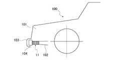
- the energy absorbing member 11 (see FIG. 1) of the first embodiment is used for absorbing the impact of the bumper of the automobile 100.
- the automobile 100 includes a side member 102 (corresponding to the “body strength member” of the present invention) that extends in the vehicle front-rear direction below the side of the engine room 101, and the interior of the bumper skin 103. Further, a bumper reinforcing member 104 extending along the vehicle width direction is provided. An energy absorbing member 11 is disposed between the side member 102 and the bumper skin 103 substantially parallel to the vehicle front-rear direction.
- the energy absorbing member 11 is provided between the front side member 102 and the bumper reinforcing member 104 of the automobile 100.
- the energy absorbing member 11 is a rear side member (see FIG. 7). (Not shown) and a bumper reinforcing member (not shown) may be provided.
- the energy absorbing member 11 is formed of a metal plate that has high rigidity and can absorb kinetic energy applied from the outside by plastic deformation.
- the energy absorbing member 11 is formed of a single aluminum plate having a thickness of about 1.8 millimeters.
- the energy absorbing member 11 can be formed of any material as long as it has good rigidity and kinetic energy absorption characteristics.
- it can also be formed of a metal other than aluminum, such as a steel plate, an aluminized steel plate, a laminate of an aluminum plate and a resin film material, a resin, and a plywood thereof.
- the energy absorbing member 11 according to the first embodiment is formed by pressing, it may be formed by any other processing method.
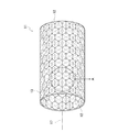
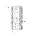
- the energy absorbing member 11 is formed in a cylindrical shape as shown in FIG.
- the energy absorbing member 11 is hollow and has openings 12 and 12 at both ends.
- the energy absorbing member 11 is fixed to the side member 102 and the bumper reinforcing member 104 with a bolt or the like (not shown). Thereby, the energy absorbing member 11 is disposed so that the virtual axis 17 (the central axis of the cylinder formed by the energy absorbing member 11) is parallel to the front-rear direction of the automobile 100.
- the energy absorbing member 11 is not limited to a cylindrical shape, and has a polygonal cylindrical shape such as a rectangular cylindrical shape, a pentagonal cylindrical shape, and a hexagonal cylindrical shape in a plan view (that is, viewed from the opening side). There may be.
- the inside of the energy absorbing member 11 may be partitioned by a partition member extending in the axial direction. Further, the energy absorbing member 11 may be fixed to the side member 102 and the bumper reinforcing member 104 by any method.
- the overall structure of the energy absorbing member 11 is not limited to the above as long as the rigidity and impact energy absorption characteristics are good.
- a structure in which plate materials are provided at both ends and the internal space is sealed may be used, or a material such as urethane may be filled therein.
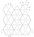
- a plurality of bulging portions 13 are formed on substantially the entire plate surface of the energy absorbing member 11 by, for example, pressing.
- the bulging portion 13 of the energy absorbing member is polygonal when viewed from the front.
- all the bulging portions 13 are formed in the same shape. That is, each bulging part 13 is the same hexagonal outer shape in front view, and the size of the bulging is the same.
- each bulging portion 13 bulges inward from the virtual outer surface 18 of the energy absorbing member 11.
- a ridge line 14 that is inclined toward the inner side of the energy absorbing member 11 is formed as shown in FIGS. 3 and 4.
- the ridge line 14 is a ridge line when viewed from the inside of the energy absorbing member 11, but is a valley line when viewed from the outside. As shown in FIGS. 3 and 4, these ridge lines 14 form a curve that curves inward, and the intersection 15 of the ridge lines 14 is the highest point in the bulging direction.
- a surface surrounded by the two ridge lines 14 and 14 of the bulging portion 13 and one side 16 of the outer shape forms a plane. All the adjacent bulging portions 13 are adjacent to each other without a gap.
- the bulging portion 13 is formed in a shape that allows good absorption of kinetic energy due to an impact received when the automobile 100 collides.
- the bulging portion 13 is formed so that one side of the outer shape is 8 millimeters and the height is 2 millimeters.
- the bulging portion 13 may be formed in any shape or size as long as energy absorption is good.
- the bulging portion 13 is disposed in such a manner that the cylindrical axial direction is not easily bent. Specifically, the bulging part 13 is arrange
- the impact load When an impact load is applied to the bumper skin 103 from the front of the automobile 100, the impact load is transmitted to the energy absorbing member 11 via the bumper reinforcing member 104. At this time, the energy absorbing member 11 is buckled in the direction of the virtual axis 17 because the buckling load is set smaller than that of the side member 102. Thereby, transmission of the load to the side member 102 can be suppressed.
- the bulging portion 13 is provided in the energy absorbing member 11, the axial drag at the initial stage of the collision can be reduced. Moreover, since the outer peripheral part of the bulging part 13 becomes a reference position at the time of buckling, the energy absorption characteristic can be adjusted by adjusting the size, arrangement position, and the like of the bulging part 13. That is, in the energy absorbing member 11 of the first embodiment, unlike the energy absorbing member having a flat side surface, the energy absorbing characteristics are adjusted without changing the wall length, plate thickness, and material. Can do.
- the bulging portion 13 is provided on substantially the entire surface of the energy absorbing member 11, high energy absorption efficiency can be obtained on the entire surface of the energy absorbing member 11. Therefore, in this Embodiment 1, when the energy absorption member 11 buckles, it can suppress bending in the direction non-parallel to the virtual axis
- the bulging portion 13 protrudes inward of the energy absorbing member 11. Therefore, when the energy absorbing member 11 is buckled, an interference reaction force effect occurs between the adjacent bulging portions 13 and 13. And the effect which absorbs an impact can be heightened by this interference reaction force effect. As a result, the energy absorbing member 11 can absorb an impact with high energy absorption efficiency.
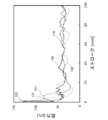
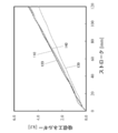
- FIG. 5 and FIG. 6 show the results of an experiment relating to the impact energy absorbed by the energy absorbing member 11.
- the vertical axis represents the reaction force (unit: kilonewtons), and the vertical axis represents the stroke (unit: millimeters).
- the vertical axis represents absorbed energy (unit: kilojoule), and the horizontal axis represents stroke (unit: millimeter).
- a curve 110 indicates that one end of the energy absorbing member 11 of the first embodiment is attached to the fixing member, and a 500 kg rigid body is freely dropped from a height of 3 m from the other end side, and the initial speed is 27.6 km.
- the state of change in reaction force and change in absorbed energy when the shaft is crushed at / h is shown.
- the energy absorbing member 11 used in the experiment is formed of a steel material of SPC440W / 1.0t (YP: 355 MPa, TS: 483 MPa, El: 33%).
- the energy absorbing member 11 has a diameter of 105 mm.
- Numeral 120 is a characteristic curve showing an experimental result of an energy absorbing member (not shown) as a first comparative example.
- the first comparative example is different in that the material, shape, and diameter of the energy absorbing member are the same as those of the energy absorbing member 11 of the first embodiment, but are formed of a flat plate without the bulging portion 13.
- Numeral 130 is a characteristic curve showing an experimental result of an energy absorbing member (not shown) as a second comparative example.
- the material, shape, diameter, size and arrangement of the bulging part of the energy absorbing member are the same as those of the energy absorbing member 11 of the first embodiment, but the bulging part is formed in a cylindrical outer side. The point which was formed so that it may protrude toward it differs.
- Numeral 140 is a characteristic curve showing an experimental result of an energy absorbing member (not shown) as a third comparative example.
- the third comparative example is the second comparative example in that the material of the energy absorbing member, the shape, the size and arrangement of the bulging portion, and the bulging portion are formed so as to protrude outward in the cylindrical shape. This is the same as the energy absorbing member 11 except that the diameter is 100 mm, which is different from the second comparative example.
- the experimental method for the first to third comparative examples is the same as the experimental method for the energy absorbing member 11 of the first embodiment.
- the initial reaction force peak (position indicated by reference numeral 111) when the energy absorbing member 11 of the first embodiment buckles is the initial reaction force peak (reference numeral 111) of the second comparative example. It is approximately 80 f / kN, similar to the position indicated by 131). This is lower than about 130 f / kN of the peak of the initial reaction force (position indicated by reference numeral 121) in the first comparative example.
- the total energy absorption amount of each energy absorbing member (that is, the total amount of impact energy absorbed by the energy absorbing member from the start to the end of buckling) is the portion between each graph and the horizontal axis. Equal to the area.
- the total absorbed energy of the energy absorbing member 11 of the first embodiment is substantially equal to the total absorbed energy of the first comparative example and the third comparative example. This is larger than the total absorbed energy of the second comparative example.
- the energy absorbing member 11 of the first embodiment is substantially equivalent to the first comparative example (that is, the energy absorbing member formed of a flat plate having no bulging portion). Although it has a collision energy absorption amount, a further feature is that the peak value of the initial load is remarkably low, and a stable reaction force can be maintained over the entire stroke even after the initial load.
- the energy absorbing member of the second comparative example is the first embodiment in that the peak value of the initial load is low and the stability of the reaction force in the stroke after the initial load. The tendency similar to that of the energy absorbing member 11 is shown. However, as shown in FIG. 6, the energy absorbing member of the second comparative example is clearly inferior to the energy absorbing member 11 according to the first embodiment in terms of the total absorbed energy.
- the energy absorbing member 11 according to the first embodiment suppresses the peak value of the initial load when the bulging portion 13 protrudes toward the inner side of the cylinder, thereby buckling.
- the impact can be absorbed with high energy absorption efficiency equivalent to that of the energy absorbing member in which the bulging portion is not formed due to the interference reaction force effect between the bulging portions 13 and 13 adjacent to each other.
- the peak value of the initial load is suppressed, the obstacle value applied to the occupant is reduced, the energy is small, the energy absorption efficiency is high, and the degree of energy absorption can be freely adjusted.
- the absorbing member 11 can be formed.
- the energy absorbing member 21 according to the second embodiment of the present invention is also used for shock absorption of the bumper of the automobile 100 shown in FIG.
- the shape of the bulging portion 22 is different from that of the bulging portion 13 according to the energy absorbing member 11 of the first embodiment.
- the bulging portion 22 of the second embodiment is formed over substantially the entire surface of the energy absorbing member 21.
- the bulging portion 22 is formed by, for example, pressing.
- the bulging portion 22 bulges inward from a virtual outer surface 28 indicated by a two-dot chain line in the drawings of the energy absorbing member 21 in FIGS. 10 and 11.
- each bulging portion 22 is a substantially rectangular shape (see the outer circumferential line 23 in FIG. 9).
- the bulging portions 22 are arranged so that the respective diagonal lines are along the axial direction and the circumferential direction of the energy absorbing member 21.
- the bulging portion 22 bulges from the outer peripheral line 23 to the inside of the energy absorbing member 21, and the size of the bulging is the same.
- a first ridge line 24 is provided on a diagonal line of the bulging portion 22 along the circumferential direction of the energy absorbing member 21 (that is, in the left-right direction in FIG. 9).
- a trough line 26 is provided on the bulging portion 22 on a diagonal line along the axial direction of the energy absorbing member 21 (that is, in the left-right direction in FIG. 9).
- a pair of second ridge lines 25 and 25 are provided on both sides of the valley line 26. As shown in FIG. 9, the second ridge lines 25, 25 have a rhombus shape in front view. One end of the first ridge line 24 is joined to the approximate center of the second ridge lines 25 and 25. Further, both end portions of the second ridge lines 25 and 25 and both end portions of the valley line 26 are separated from the outer peripheral line 23.
- the first ridge line 24 and the second ridge line 25 are ridge lines when viewed from the inside of the energy absorbing member 21, but are valley lines when viewed from the outside.
- the valley line 26 is a valley line when viewed from the inside of the energy absorbing member 21, but becomes a ridge line when viewed from the outside.
- the distance L1 between the valley line 26 and the virtual axis 17 of the energy absorbing member 21 shown in FIG. 10 is set to be longer than the distance L2 between the outer peripheral line 23 and the virtual axis 17.
- the energy absorbing member 21 of the second embodiment can absorb an impact with high energy absorption efficiency when the plate-like member is buckled by providing the bulging portion 22 having a substantially rectangular outer edge shape. Further, the bulging portion 22 has a first ridge line 24 formed along one diagonal line and a valley line along the other diagonal line in addition to the outer edge shape being formed in a substantially rectangular shape in front view. Since 26 is formed, it is possible to increase the resistance to an impact applied from the outside toward each diagonal direction of the energy absorbing member.
- the outer peripheral line 23 and the first ridge line 24 of the bulging portion 22 serve as reference positions for buckling, and the function as a “tension” in which the valley line 26 exerts a drag in the buckling direction. Fulfill. Therefore, the energy absorbing member 21 according to the second embodiment can adjust the axial resistance and the deformation mode against buckling without changing the wall length, the plate thickness, and the material, and the energy absorbing member 21 Strength can be increased. Thereby, in this Embodiment 2, the energy absorption member 21 which is small, has high energy absorption efficiency, and can adjust the degree of energy absorption freely can be obtained.
- both end portions of the second ridge lines 25 and 25 and both end portions of the valley line 26 are formed apart from the outer peripheral line 23.
- both end portions of the second ridge lines 25 and 25 and You may form so that the both ends of the valley line 26 may join to the outer periphery line 23.
- a ridgeline (1st ridgeline 24) is provided on the diagonal along the circumferential direction of the energy absorption member 21 of the bulging part 22, and on the diagonal along the axial direction of the energy absorption member 21
- the valley line 26 is provided, but conversely, the valley line may be provided on the diagonal line along the circumferential direction of the energy absorbing member 21 and the ridge line may be provided on the diagonal line along the axial direction.
- the energy absorbing member may be polygonal, the partition member may be provided inside, the plate member may be provided at both ends and sealed, and the inside is filled with urethane or the like
- the point etc. which may provide a material are the same as that of the said Embodiment 1.
- Embodiment 3 of the present invention is also used to absorb the impact of the bumper of automobile 100 (see FIG. 7).
- This energy absorbing member (not shown) is different from the bulging portions 13 and 22 of the energy absorbing members 11 and 21 of the first and second embodiments in the shape of the bulging portion (not shown). Specifically, the bulging portion (not shown) of the third embodiment is formed so as to be circular in plan view. The rest is the same as in the first and second embodiments.
- the shape of the bulging portion may be elliptical in plan view.
- the energy absorbing member may be polygonal, the partition member may be provided inside, the plate material may be provided at both ends and sealed, and the inside is filled with urethane or the like
- the point etc. which may provide a material are the same as that of the said Embodiment 1.
- the energy absorbing member 41 according to the fourth embodiment of the present invention is also used for shock absorption of the bumper of the automobile 100 (see FIG. 7).
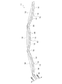
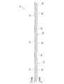
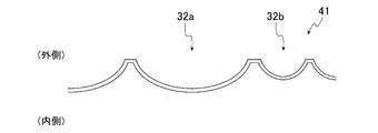
- FIG. 12A is a side view conceptually showing the structure of the energy absorbing member 41 according to the fourth embodiment. 13 is a partially enlarged view of FIG. 12A, and FIG. 14 is a cross-sectional view taken along the line GG of FIG.
- the overall shape of the energy absorbing member 41 is substantially cylindrical. Is formed.
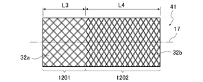
- two areas 1201 and 1202 are set along the direction of the virtual axis 17 of the energy absorbing member 41.
- bulged portions 32a and 32b having different shapes are formed.
- a bulging portion 32 a is formed in the area 1201
- a bulging portion 32 b is formed in the area 1202.
- the bulging part 32a and the bulging part 32b are both rectangular.
- the bulging portion 32a and the bulging portion 32b have the same diagonal dimension in the circumferential direction (vertical direction in FIG. 12A), but the dimension in the direction parallel to the shaft 17 (horizontal direction in FIG. 12A)
- the bulging part 32a is longer than the bulging part 32b.
- the bulging portions 32a and 32b bulge inward from the side surface of the energy absorbing member 41, and the bulging portion 32a is formed deeper than the bulging portion 32b.
- the bulging portions 32a and 32b may have the same depth.
- the bulging portions 32a and 32b can be formed by, for example, pressing.
- the bulging portion 32a of the area 1201 and the bulging portion 32b of the area 1202 are formed in different shapes. For this reason, the axial drag and the impact energy absorption efficiency when an impact in the direction of the shaft 17 is applied to the energy absorbing member 41 are different in the area 1201 and the area 1202.
- FIG. 15 shows the results of an experiment relating to impact energy absorbed by the energy absorbing member 41.
- the vertical axis represents the reaction force (unit: kilonewtons) and the horizontal axis represents the stroke (unit: millimeters), but the coordinates are relative values.
- an energy absorbing member having a total length in the direction of the axis 17 (see FIG. 12A) of 250 mm was used.
- a characteristic curve 1510 shows an experimental result of the energy absorbing member 41 having a length L3 of 198 mm (and thus a length L4 of 52 mm).
- a measurement point 1511 is a peak reaction force at the beginning of the collision in the curve 1510.
- the characteristic curve 1520 shows the experimental results of the energy absorbing member 41 having a length L3 of 224 mm (thus, the length L4 is 26 mm).
- a measurement point 1521 is a peak reaction force at the beginning of the collision in the curve 1520.
- a characteristic curve 1530 is a comparative example (an energy absorbing member that belongs to the present invention but does not belong to the fourth embodiment), and only a substantially square bulging portion 32a is formed over the entire side surface. The experimental results of the energy absorbing member are shown.
- a measurement point 1531 is a peak reaction force at the beginning of the collision in the curve 1530.
- the energy absorbing member 41 according to the fourth embodiment (corresponding to the characteristic curves 1510 and 1520) has a peak reaction force at the initial stage of the collision as compared with the comparative example (corresponding to the characteristic curve 1530). It was possible to reduce. On the other hand, the reaction force other than the initial stage of the collision is substantially equal between the energy absorbing member 41 according to the fourth embodiment and the comparative example.
- the arrangement direction is arbitrary, but the bulging portion 32b (area 1202) having the smaller axial drag force. It is more desirable to place the on the bumper side.
- the peak value of the initial load is suppressed by providing the energy absorbing member 41 with a plurality of types (here, two types) of regions having different axial drag and impact energy absorption efficiency. It is possible to obtain an energy absorbing member 41 that is small in size, has high energy absorption efficiency, and can freely adjust the degree of energy absorption while reducing the obstacle value applied to the occupant.
- the energy absorbing member may be polygonal, the partition member may be provided inside, the plate member may be provided at both ends and sealed, and the interior is filled with urethane or the like
- the point etc. which may provide a material are the same as that of the said Embodiment 1.
- Embodiment 5 of the Invention The energy absorbing member according to Embodiment 5 of the present invention is also used to absorb the impact of the bumper of automobile 100 (see FIG. 7).
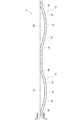
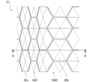
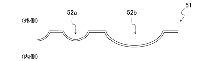
- FIG. 16A and 16B are conceptual diagrams showing the configuration of the energy absorbing member 51 according to the fifth embodiment, where FIG. 16A is a plan view and FIG. 16B is a cross-sectional view taken along the line HH in FIG. 16A.
- two areas 1601 and 1602 are set along the axial direction of the cylinder.
- bulged portions 52a and 52b having different shapes are formed.
- a bulge portion 52a having a hexagonal shape and a small size is formed in the area 1601
- a bulge portion 52b having a large size and a hexagonal shape in plan view is formed in the area 1602. ing.
- the bulging portions 52a and 52b bulge inside the energy absorbing member 51, and the bulging portion 52a is formed deeper than the bulging portion 52b.
- the bulging portions 52a and 52b may have the same depth.
- the three-dimensional shape of the bulging portions 52a and 52b is the same as that in the first embodiment.
- the bulging portions 52a and 52b can be formed by, for example, pressing.
- the length of the areas 1601 and 1602 (the length in the direction of the axis 17) is not particularly limited, which is the same as in the fourth embodiment.
- the axial drag and the impact energy absorption amount when an axial impact is applied are different in the area 1601 and the area 1602.
- the peak reaction force at the initial stage of the collision can be kept low as compared with the case where the size of the bulging portion is constant, and the reaction force after the initial stage of the collision is greatly reduced. It can be low and stable.
- the energy absorbing member 41 by providing the energy absorbing member 41 with a plurality of types (two types in this case) of areas having different axial drag and impact energy absorption efficiency, the peak value of the initial load is suppressed and the occupant is affected. It is possible to obtain the energy absorbing member 51 that is small in size, has high energy absorption efficiency, and can freely adjust the degree of energy absorption while reducing the obstacle value.
- the energy absorbing member may be polygonal, the partition member may be provided inside, the plate member may be provided at both ends and sealed, and the inside is filled with urethane or the like
- the point etc. which may provide a material are the same as that of the said Embodiment 1.
- Embodiment 6 of the present invention is also used to absorb the impact of the bumper of automobile 100 (see FIG. 7).
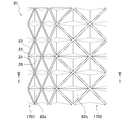
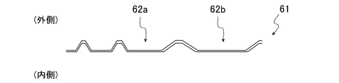
- FIGS. 17A and 17B are conceptual diagrams showing the configuration of the energy absorbing member 61 according to Embodiment 6, FIG. 17A is a plan view, and FIG. 17B is a cross-sectional view taken along the line II of FIG. 17A.
- two areas 1701 and 1702 are set along the axial direction of the cylinder.
- different bulging portions 62a and 62b are formed. Specifically, a small-size bulge 62a is formed in the area 1701, and a large-size bulge 62b is formed in the area 1702.
- the shapes of the bulging portions 62a and 62b are substantially the same as those of the bulging portion 22 according to the second embodiment.
- both ends of the second ridge lines 25 and 25 and both ends of the valley line 26 are joined to the outer peripheral line 23.
- both ends and valleys of the second ridge lines 25 and 25 are formed. Both ends of the line 26 may be separated from the outer peripheral line 23.
- the bulging portions 62 a and 62 b bulge inside the energy absorbing member 61.
- the depths of the bulging portions 62a and 62b are substantially the same, but the bulging portion 62a may be formed deeper than the bulging portion 62b.
- the bulging portions 62a and 62b can be formed by, for example, pressing.
- the lengths of the areas 1701 and 1702 are not particularly limited, which is the same as in the fourth embodiment.
- the axial drag and the impact energy absorption amount when an axial impact is applied are different in the area 1701 and the area 1702.
- the peak reaction force at the initial stage of the collision can be kept low as compared with the case where the size of the bulging portion is constant, and the reaction force after the initial stage of the collision is greatly reduced. It can be low and stable. .
- the energy absorbing member 41 by providing the energy absorbing member 41 with a plurality of types (two types in this case) of areas having different axial drag and impact energy absorption efficiency, the peak value of the initial load is suppressed and the passenger is applied to the occupant. It is possible to obtain the energy absorbing member 61 that is small in size, has high energy absorption efficiency, and can freely adjust the degree of energy absorption while reducing the obstacle value.
- the energy absorbing member may be polygonal, the partition member may be provided inside, the plate member may be provided at both ends and sealed, and the interior is filled with urethane or the like
- the point etc. which may provide a material are the same as that of the said Embodiment 1.
- Embodiment 7 of the present invention is also used to absorb the bumper impact of automobile 100 (see FIG. 7).
- This energy absorbing member (not shown) is different from Embodiments 4 to 6 in the shape of the bulging portion (not shown). Specifically, the bulging portion (not shown) of the seventh embodiment is formed so as to be circular in plan view. The rest is the same as in the fourth to seventh embodiments.
- the shape of the bulging portion may be an elliptical shape in plan view.
- the energy absorbing member may be polygonal, the partition member may be provided inside, the plate member may be provided at both ends and sealed, and the inside is filled with urethane or the like
- the point etc. which may provide a material are the same as that of the said Embodiment 1.
- the bulging portions are adjacent to each other. However, the bulging portions are close to each other, and a gap is formed between the bulging portions (that is, the bulging portions).
- the configuration in which the original flat surface of the plate-like member remains between the portions may be employed.
- the energy absorbing member is provided between the side member 102 of the automobile 100 and the bumper reinforcing member 104.
- the energy absorbing member of the present invention may be provided at another part of the vehicle body. it can.
- the energy absorbing member of the present invention can be applied to things other than automobiles.
Landscapes
- Engineering & Computer Science (AREA)
- General Engineering & Computer Science (AREA)
- Mechanical Engineering (AREA)
- Vibration Dampers (AREA)
Abstract
La présente invention vise à fournir un élément d'absorption d'énergie ayant une résistance axiale suffisamment faible en début de collision mais capable d'absorber une quantité d'énergie suffisamment grande pendant toute la durée de la collision. L'élément d'absorption d'énergie (11) présente une forme plus ou moins cylindrique avec des ouvertures (12, 12) aux deux extrémités. Une pluralité de parties convexes (13) adjacentes ou proches les unes des autres sont formées sur la face latérale de la forme cylindrique. Les parties convexes (13) font saillie vers l'intérieur de l'élément d'absorption d'énergie. Étant donné que les parties convexes (13) font saillie vers l'intérieur de l'élément d'absorption d'énergie (11), une résistance axiale peut être réduite en début de collision, et la quantité totale d'absorption de l'énergie d'impact peut être accrue.
Applications Claiming Priority (2)
| Application Number | Priority Date | Filing Date | Title |
|---|---|---|---|
| JP2011-105505 | 2011-05-10 | ||
| JP2011105505A JP2014141977A (ja) | 2011-05-10 | 2011-05-10 | エネルギー吸収部材 |
Publications (1)
| Publication Number | Publication Date |
|---|---|
| WO2012153792A1 true WO2012153792A1 (fr) | 2012-11-15 |
Family
ID=47139267
Family Applications (1)
| Application Number | Title | Priority Date | Filing Date |
|---|---|---|---|
| PCT/JP2012/061940 Ceased WO2012153792A1 (fr) | 2011-05-10 | 2012-05-10 | Élément d'absorption d'énergie |
Country Status (2)
| Country | Link |
|---|---|
| JP (1) | JP2014141977A (fr) |
| WO (1) | WO2012153792A1 (fr) |
Cited By (1)
| Publication number | Priority date | Publication date | Assignee | Title |
|---|---|---|---|---|
| WO2014126183A1 (fr) * | 2013-02-18 | 2014-08-21 | 株式会社深井製作所 | Elément d'absorption d'énergie |
Families Citing this family (1)
| Publication number | Priority date | Publication date | Assignee | Title |
|---|---|---|---|---|
| JP7371042B2 (ja) * | 2021-03-22 | 2023-10-30 | 豊田鉄工株式会社 | 車両用エネルギー吸収構成部材 |
Citations (6)
| Publication number | Priority date | Publication date | Assignee | Title |
|---|---|---|---|---|
| DE19858432A1 (de) * | 1998-12-17 | 2000-07-06 | Mirtsch Gmbh Dr | Energieabsorbierendes Deformationselement |
| JP2002347548A (ja) * | 2001-05-29 | 2002-12-04 | Toyotomi Kiko Co Ltd | エネルギー吸収部材 |
| JP2009113675A (ja) * | 2007-11-07 | 2009-05-28 | Toyota Motor Corp | 車両用エネルギー吸収部材、車両前部構造、及び車両後部構造。 |
| JP2010018047A (ja) * | 2008-07-08 | 2010-01-28 | Kobe Steel Ltd | 車両のバンパーシステム |
| JP2010149771A (ja) * | 2008-12-26 | 2010-07-08 | Toyoda Iron Works Co Ltd | 車両用衝撃吸収部材 |
| JP2010280309A (ja) * | 2009-06-05 | 2010-12-16 | Mazda Motor Corp | 車両用衝撃吸収構造体 |
-
2011
- 2011-05-10 JP JP2011105505A patent/JP2014141977A/ja not_active Withdrawn
-
2012
- 2012-05-10 WO PCT/JP2012/061940 patent/WO2012153792A1/fr not_active Ceased
Patent Citations (6)
| Publication number | Priority date | Publication date | Assignee | Title |
|---|---|---|---|---|
| DE19858432A1 (de) * | 1998-12-17 | 2000-07-06 | Mirtsch Gmbh Dr | Energieabsorbierendes Deformationselement |
| JP2002347548A (ja) * | 2001-05-29 | 2002-12-04 | Toyotomi Kiko Co Ltd | エネルギー吸収部材 |
| JP2009113675A (ja) * | 2007-11-07 | 2009-05-28 | Toyota Motor Corp | 車両用エネルギー吸収部材、車両前部構造、及び車両後部構造。 |
| JP2010018047A (ja) * | 2008-07-08 | 2010-01-28 | Kobe Steel Ltd | 車両のバンパーシステム |
| JP2010149771A (ja) * | 2008-12-26 | 2010-07-08 | Toyoda Iron Works Co Ltd | 車両用衝撃吸収部材 |
| JP2010280309A (ja) * | 2009-06-05 | 2010-12-16 | Mazda Motor Corp | 車両用衝撃吸収構造体 |
Cited By (1)
| Publication number | Priority date | Publication date | Assignee | Title |
|---|---|---|---|---|
| WO2014126183A1 (fr) * | 2013-02-18 | 2014-08-21 | 株式会社深井製作所 | Elément d'absorption d'énergie |
Also Published As
| Publication number | Publication date |
|---|---|
| JP2014141977A (ja) | 2014-08-07 |
Similar Documents
| Publication | Publication Date | Title |
|---|---|---|
| CN114728674B (zh) | 车辆侧结构 | |
| US10611409B2 (en) | Twelve-cornered strengthening member | |
| US8459726B2 (en) | Multi-cornered strengthening members | |
| JP5949925B2 (ja) | クラッシュボックス及び自動車車体 | |
| JP5078597B2 (ja) | 衝撃吸収構造 | |
| JP6703322B1 (ja) | 自動車骨格部材および電気自動車 | |
| JP7734699B2 (ja) | 車両構造体 | |
| EP3636496A1 (fr) | Configuration appliquée aux pare-chocs de véhicules automobiles | |
| JP2009113675A (ja) | 車両用エネルギー吸収部材、車両前部構造、及び車両後部構造。 | |
| JP6369441B2 (ja) | 車両下部構造 | |
| JP2011057158A (ja) | 車両用衝撃吸収具及び車両用バンパ装置 | |
| JP6254448B2 (ja) | 車両用バンパビーム | |
| WO2014126183A1 (fr) | Elément d'absorption d'énergie | |
| JP5053762B2 (ja) | 車両用バンパ装置 | |
| US10695817B2 (en) | Thirty-six-cornered strengthening member | |
| WO2012153792A1 (fr) | Élément d'absorption d'énergie | |
| US10065682B1 (en) | Thirty-two-cornered strengthening member | |
| JP5542082B2 (ja) | 車輌用フードパネル | |
| JP2014058221A (ja) | 車両用バンパビーム | |
| US10144454B1 (en) | Thirty-six cornered vehicle beam | |
| KR101270939B1 (ko) | 차량용 크래쉬 박스 | |
| JP5333352B2 (ja) | 車両端部構造 | |
| JP2018111378A (ja) | 車両用バンパ構造 | |
| JP5254662B2 (ja) | 車両用衝撃吸収具及び車両用バンパ装置 | |
| JP6370690B2 (ja) | 車両用バンパ装置 |
Legal Events
| Date | Code | Title | Description |
|---|---|---|---|
| 121 | Ep: the epo has been informed by wipo that ep was designated in this application |
Ref document number: 12782924 Country of ref document: EP Kind code of ref document: A1 |
|
| NENP | Non-entry into the national phase |
Ref country code: DE |
|
| 122 | Ep: pct application non-entry in european phase |
Ref document number: 12782924 Country of ref document: EP Kind code of ref document: A1 |
|
| NENP | Non-entry into the national phase |
Ref country code: JP |