WO2012153852A1 - 扉開閉装置用踏み板機構 - Google Patents
扉開閉装置用踏み板機構 Download PDFInfo
- Publication number
- WO2012153852A1 WO2012153852A1 PCT/JP2012/062212 JP2012062212W WO2012153852A1 WO 2012153852 A1 WO2012153852 A1 WO 2012153852A1 JP 2012062212 W JP2012062212 W JP 2012062212W WO 2012153852 A1 WO2012153852 A1 WO 2012153852A1
- Authority
- WO
- WIPO (PCT)
- Prior art keywords
- door
- tread
- door opening
- link
- closing device
- Prior art date
- Legal status (The legal status is an assumption and is not a legal conclusion. Google has not performed a legal analysis and makes no representation as to the accuracy of the status listed.)
- Ceased
Links
Images




Classifications
-
- E—FIXED CONSTRUCTIONS
- E05—LOCKS; KEYS; WINDOW OR DOOR FITTINGS; SAFES
- E05F—DEVICES FOR MOVING WINGS INTO OPEN OR CLOSED POSITION; CHECKS FOR WINGS; WING FITTINGS NOT OTHERWISE PROVIDED FOR, CONCERNED WITH THE FUNCTIONING OF THE WING
- E05F13/00—Mechanisms operated by the movement or weight of a person or vehicle
- E05F13/02—Mechanisms operated by the movement or weight of a person or vehicle by devices, e.g. lever arms, affected by the movement of the user
-
- E—FIXED CONSTRUCTIONS
- E05—LOCKS; KEYS; WINDOW OR DOOR FITTINGS; SAFES
- E05F—DEVICES FOR MOVING WINGS INTO OPEN OR CLOSED POSITION; CHECKS FOR WINGS; WING FITTINGS NOT OTHERWISE PROVIDED FOR, CONCERNED WITH THE FUNCTIONING OF THE WING
- E05F1/00—Closers or openers for wings, not otherwise provided for in this subclass
- E05F1/02—Closers or openers for wings, not otherwise provided for in this subclass gravity-actuated, e.g. by use of counterweights
-
- E—FIXED CONSTRUCTIONS
- E05—LOCKS; KEYS; WINDOW OR DOOR FITTINGS; SAFES
- E05F—DEVICES FOR MOVING WINGS INTO OPEN OR CLOSED POSITION; CHECKS FOR WINGS; WING FITTINGS NOT OTHERWISE PROVIDED FOR, CONCERNED WITH THE FUNCTIONING OF THE WING
- E05F1/00—Closers or openers for wings, not otherwise provided for in this subclass
- E05F1/08—Closers or openers for wings, not otherwise provided for in this subclass spring-actuated, e.g. for horizontally sliding wings
- E05F1/16—Closers or openers for wings, not otherwise provided for in this subclass spring-actuated, e.g. for horizontally sliding wings for sliding wings
-
- E—FIXED CONSTRUCTIONS
- E05—LOCKS; KEYS; WINDOW OR DOOR FITTINGS; SAFES
- E05F—DEVICES FOR MOVING WINGS INTO OPEN OR CLOSED POSITION; CHECKS FOR WINGS; WING FITTINGS NOT OTHERWISE PROVIDED FOR, CONCERNED WITH THE FUNCTIONING OF THE WING
- E05F11/00—Man-operated mechanisms for operating wings, including those which also operate the fastening
- E05F11/54—Man-operated mechanisms for operating wings, including those which also operate the fastening for doors
-
- E—FIXED CONSTRUCTIONS
- E05—LOCKS; KEYS; WINDOW OR DOOR FITTINGS; SAFES
- E05F—DEVICES FOR MOVING WINGS INTO OPEN OR CLOSED POSITION; CHECKS FOR WINGS; WING FITTINGS NOT OTHERWISE PROVIDED FOR, CONCERNED WITH THE FUNCTIONING OF THE WING
- E05F13/00—Mechanisms operated by the movement or weight of a person or vehicle
- E05F13/04—Mechanisms operated by the movement or weight of a person or vehicle by platforms lowered by the weight of the user
Definitions
- the present invention relates to a door opening / closing device tread mechanism, and more specifically, a door opening / closing mechanism having a structure in which the tread board mechanism is driven by a stepping force of a passing person and the door is returned by an internal return mechanism after the passing person passes.
- the present invention relates to a footboard mechanism for an apparatus.
- Patent Document 1 there is a door opening and closing device as shown in Patent Document 1 (see FIG. 8).
- This door opening and closing device is a mechanism in which a portion directly under the door is lifted and the front and rear ends are fixed by a hinge as viewed from a passing person.
- the restoring force of the footboard is linked to the force of closing the door, and requires a large space in the balustrade.
- the acting force changes depending on the stepping position.
- Patent Document 2 Although the door opening and closing device of Patent Document 2 (see FIG. 9) has a structure in which no mechanism is provided in the space portion, a large mechanism is provided in the door pocket portion, and it is necessary to secure a space for this at the time of building design. .
- a conventional door opening / closing device based on the weight of a passing person is composed of a floor tread mechanism, a door pocket, and a driving mechanism for a balustrade part, and requires a large space to be provided in the space of the floor surface part, the door pocket part and the balustrade part.
- an object of the present invention is to make the tread mechanism thin and to make the tread that has been lowered by the load of the passing person to be a self-returning structure that automatically rises after passing, making it function in a smaller space, and opening and closing the door with good workability
- the object is to provide a footboard mechanism for a device.
- the door opening / closing device tread mechanism is for a door opening / closing device that opens and closes the door using the displacement of the tread plate mechanism installed on the front and rear floors of the door as viewed from the passing person and the tread plate descends as a power source. It is a footboard mechanism, characterized in that a return mechanism is provided for applying a biasing force to the footboard to return the footboard lowered by the passing person's load to the original position after the passing person passes.
- the door opening / closing device tread mechanism includes a tread plate provided with a plurality of bearings, a plurality of links that connect one end to the bearing of the tread plate, and a bearing that is provided on a floor surface fixing portion and connects the other end of the link.
- the door opening / closing device tread mechanism is constituted by one of the treads provided with the interlocking guide and the other treads provided with the interlocking guide receiving member slidably coupled to the interlocking guide.
- the return mechanism includes an extension link that extends the other end side of the link in a direction opposite to the tread plate, and a weight that is axially supported by an extension end of the extension link.
- the weight rises when a passing person gets on the tread board and the tread board descends, and when the passing person gets off the tread board, the weight descends by its own weight to raise the tread board.
- the door opening / closing device tread mechanism includes a bearing fixed to the tread plate fixing portion and a torsion spring attached coaxially, and a passer gets on the tread and the tread is lowered.
- the urging force of the torsion spring is accumulated, and when the passer gets down the tread, the tread is raised by releasing the urging force of the torsion spring.
- An upper end of the door is slidably attached to a hanging door rail, and the hanging door rail is inclined downward in either of the door opening and closing directions.
- the door opening / closing device tread mechanism of the present invention can be easily installed because it does not require a large installation space on the floor surface before and after the door, the door pocket, and the space.
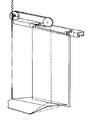
- Example 1 is an external view of an opening / closing device using a door plate mechanism for a door opening / closing device according to the present invention.
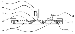
- Example 1 It is a front view of the foot board mechanism for door opening and closing devices according to the present invention.
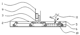
- Example 1 It is the state which stepped on in the front view of the foot board mechanism for door opening and closing devices by this invention.
- Example 1 It is a front view of the foot board mechanism for door opening and closing devices according to the present invention.
- Example 2 It is a top view of the link and torsion spring part of a foot board mechanism for door opening and closing devices by the present invention.
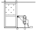
- Example 2 In the modification of this invention, it is an external view of the opening / closing apparatus using the foot board mechanism for door opening / closing apparatuses.
- the door opening / closing device tread mechanism of the present invention does not require a large installation space on the floor surface before and after the door, the door pocket part, and the balustrade part, and enables easy installation.
- FIGS. 1 uses a weight 7 as a return mechanism of the present invention, and includes a footboard mechanism (S1) composed of a footboard 2, an interlocking guide 3, a link 5, and a bearing 6, a door 1, a drive arm 4, a suspension door rail 8, And a door opening / closing mechanism (D) composed of the guide 9.
- S1 a footboard mechanism
- D a door opening / closing mechanism
- Example 1 since the guide 9 enclosed in the lower arm is used as the drive mechanism, when the tread mechanism according to the present invention is used, it is not necessary to install the mechanism in the door pocket. That is, since there is no suspension door rail 8 above the door 1, no structure other than the door 1, the suspension door rail 8, and the footboard mechanism is required.
- the hanging door rail 8 is inclined downward in either one of the opening and closing directions of the door 1. Since the upper end of the door 1 is slidably attached to the suspension door rail 8, one of the opening and closing operations of the door 1 can be performed more smoothly.
- the return energy is not a mechanical force such as a spring but a weight 7 whose performance does not change, a stable return force can be obtained over a long period of time, and the need for inspection and maintenance can be reduced. .
- the torsion spring 10 is used as the return mechanism of the present invention, and the door opening / closing device tread mechanism (S2) including the tread plate 2, the interlocking guide 3, the link 5, and the bearing 6, the door 1, the drive arm 4, and the suspension door rail.
- the door opening / closing mechanism (D) constituted by 8 and the guide 9 will be described with reference to FIGS.
- the door opening / closing device tread plate mechanism using the torsion spring 10 as the return mechanism of the present invention is mounted coaxially with the bearing 6 fixed to the fixed portion instead of the weight 7 of the above-described step plate mechanism, and one end is fixed to the fixed portion. This is a method in which the other end is fixed to the link 5 and the tread plate 2 is returned by the repulsive force of the torsion spring 10 shown in FIG.
- the link 5, the torsion spring 10, the bearing 6, and the like are provided on both side portions of the tread plate 2, and no members are present immediately below the tread plate 2, so when the tread plate 2 is stepped down, it is lowered to the bottom surface of the tread plate mechanism. And a thin footboard mechanism can be obtained.
- the present invention can also be applied to a footboard mechanism of another door opening / closing device that opens and closes using the displacement of the footboard 2 as a power source.
- the weight 7 that rises when the footboard 2 is lowered A structure for lowering and raising the tread board 2 after passing by the passing person, a spring for accumulating urging force when the tread board 2 descends and releasing the urging force to raise the tread board 2 when the passing person gets down the tread board 2
- a configuration using the biasing means can be employed as the return mechanism.
- the footboard 2 and the connecting rod 13 are connected by a link 5.
- a bearing 6 a is attached to the connecting rod 13.
- the bearing 6a is rotatable on the floor surface.
- An extension link extends from the link 5 on one end side of the footboard 2, and a weight 7 is attached to the extension link.
- a guide 12 for guiding the tread board 2 in the vertical direction is disposed around the tread board 2.
- the tread board 2 is stepped on, it is guided by the guide 12 and descends. Thereby, force is transmitted from the interlocking guide 3 and the drive arm 4 to the door opening / closing mechanism (D).
- the connecting rod 13 moves in the horizontal direction as the bearing 6a rotates.
- the link 5 lifts the weight 7 attached to the extension link with the bearing 6a of the floor surface fixing portion as a fulcrum. If the passing person passes, the weight 7 is lowered and the tread board 2 is raised and returned.
- the extension link to which the weight 7 is attached does not extend from the link 5, and one end of the coil spring 10 a is attached to the connecting rod 13.
- the other end of the coil spring 10a is attached to the floor surface.
- the tread board 2 When the tread board 2 is depressed, it is guided by the guide 12 and descends. Thereby, force is transmitted from the interlocking guide 3 and the drive arm 4 to the door opening / closing mechanism (D).
- the connecting rod 13 moves in the direction of the arrow as the bearing 6a rotates, thereby extending the coil spring 10a.
- the coil spring 10a contracts, so that the footboard 2 rises and returns.
- the door opening / closing device using the door opening / closing device tread mechanism according to the present invention does not use electricity. Therefore, (1) Places where electromagnetic waves are disliked, (2) Places where there is a risk of electric leakage or electric shock and a lot of water is used, (3) Places where few people pass and avoid standby current, (4) Carrying luggage in both hands It is suitable for entrances and exits of warehouses where there are many people passing through, and it can minimize the work involved in installation.
Landscapes
- Vehicle Step Arrangements And Article Storage (AREA)
- Power-Operated Mechanisms For Wings (AREA)
- Specific Sealing Or Ventilating Devices For Doors And Windows (AREA)
- Floor Finish (AREA)
- Mechanical Control Devices (AREA)
Abstract
Description
また、扉開閉装置用踏み板機構は、複数の軸受けを設けた前記踏み板と、前記踏み板の軸受けに一端を連結する複数のリンクと、床面固定部分に設けられ前記リンクの他端を連結する軸受けと、を備え、前記踏み板が通過者の進行方向へ円弧運動しながら、かつ水平状態を維持し、下降する扉開閉装置用踏み板機構であって、前記復帰機構は、通過者の荷重で倒れる方向に変化した前記リンクの角度を、通過後、元の角度に戻す付勢力を前記リンクに付加することを特徴とする。
また、扉開閉装置用踏み板機構は、連動ガイドを設けた一方の前記踏み板と、前記連動ガイドに、摺動自在に連結する連動ガイド受け部材を設けた他方の踏み板とで構成し、前記一方の踏み板が定量移動しながら下降した時、前記他方の踏み板も前記一方の踏み板と同様に、扉を対称軸として線対称に定量移動しながら降下することを特徴とする。
また、扉開閉装置用踏み板機構は、前記復帰機構を、前記リンクの他端側を前記踏み板と反対方向に延長した延長リンクと、延長リンクの延長端部に軸支持した錘と、から構成し、通過者が前記踏み板に乗り前記踏み板が下降したとき前記錘が上昇し、通過者が前記踏み板を降りたとき前記錘が自重で下降して前記踏み板を上昇させることを特徴とする。
また、扉開閉装置用踏み板機構は、前記復帰機構を、前記踏み板の固定部に固定された軸受けと、同軸に取り付けたねじりバネから構成し、通過者が前記踏み板に乗り前記踏み板が下降したとき前記ねじりバネの付勢力を蓄積し通過者が前記踏み板を降りたとき前記ねじりバネの付勢力を開放することにより前記踏み板を上昇させることを特徴とする。
前記扉は、上端がスライド可能に吊戸レールに取り付けられ、前記吊戸レールは、前記扉の開閉方向のいずか一方に下降傾斜していることを特徴とする。
2 踏み板
3 連動ガイド
4 駆動アーム
5 リンク
6 軸受け
6a 軸受け
7 錘
8 吊戸レール
9 ガイド
10 ねじりバネ
10a コイルバネ
11 通過する者の足
12 ガイド
13 連結棒
S1 踏み板機構(実施例1)
S2 踏み板機構(実施例2)
D 扉開閉機構
Claims (6)
- 通過者から見て扉の前後床面に設置した踏み板機構の踏み板が踏み込まれ、前記踏み板が降下する変位を動力源として扉を開閉する扉開閉装置用踏み板機構であって、
通過者の荷重で降下した前記踏み板を、通過者の通過後、元の位置に戻す付勢力を前記踏み板に付加する復帰機構を設けたことを特徴とする扉開閉装置用踏み板機構。
- 複数の軸受けを設けた前記踏み板と、
前記踏み板の軸受けに一端を連結する複数のリンクと、
床面固定部分に設けられ前記リンクの他端を連結する軸受けと、を備え、
前記踏み板が通過者の進行方向へ円弧運動しながら、かつ水平状態を維持し、下降する扉開閉装置用踏み板機構であって、
前記復帰機構は、通過者の荷重で倒れる方向に変化した前記リンクの角度を、通過後、元の角度に戻す付勢力を前記リンクに付加することを特徴とする請求項1に記載の扉開閉装置用踏み板機構。
- 連動ガイドを設けた一方の前記踏み板と、
前記連動ガイドに、摺動自在に連結する連動ガイド受け部材を設けた他方の踏み板とで構成し、
前記一方の踏み板が定量移動しながら下降した時、前記他方の踏み板も前記一方の踏み板と同様に、扉を対称軸として線対称に定量移動しながら降下することを特徴とする請求項2に記載の扉開閉装置用踏み板機構。
- 前記復帰機構を、前記リンクの他端側を前記踏み板と反対方向に延長した延長リンクと、延長リンクの延長端部に軸支持した錘と、から構成し、
通過者が前記踏み板に乗り前記踏み板が下降したとき前記錘が上昇し、通過者が前記踏み板を降りたとき前記錘が自重で下降して前記踏み板を上昇させることを特徴とする請求項2又は3に記載の扉開閉装置用踏み板機構。
- 前記復帰機構を、前記踏み板の固定部に固定された軸受けと、同軸に取り付けたねじりバネから構成し、
通過者が前記踏み板に乗り前記踏み板が下降したとき前記ねじりバネの付勢力を蓄積し、通過者が前記踏み板を降りたとき前記ねじりバネの付勢力を開放することにより前記踏み板を上昇させることを特徴とする請求項1乃至3のいずれか1項に記載の扉開閉装置用踏み板機構。
- 前記扉は、上端がスライド可能に吊戸レールに取り付けられ、前記吊戸レールは、前記扉の開閉方向のいずか一方に下降傾斜していることを特徴とする請求項1乃至3のいずれか1項に記載の扉開閉装置用踏み板機構。
Priority Applications (7)
| Application Number | Priority Date | Filing Date | Title |
|---|---|---|---|
| RU2013153892/12A RU2604483C2 (ru) | 2011-05-11 | 2012-05-11 | Механизм напольной панели для устройства открывания/закрывания двери |
| CN201280034504.4A CN103842604B (zh) | 2011-05-11 | 2012-05-11 | 门开关装置用踏板机构 |
| US14/116,819 US9447624B2 (en) | 2011-05-11 | 2012-05-11 | Step plate mechanism for door opening and closing device |
| KR1020137032879A KR101984325B1 (ko) | 2011-05-11 | 2012-05-11 | 문 개폐 장치용 발판 기구 |
| EP12782888.7A EP2711494B1 (en) | 2011-05-11 | 2012-05-11 | Step plate mechanism for door opening and closing device |
| PH1/2013/502534A PH12013502534A1 (en) | 2011-05-11 | 2012-05-11 | Step plate mechanism for door opening and closing device |
| JP2013514076A JP5985470B2 (ja) | 2011-05-11 | 2012-05-11 | 扉開閉装置用踏み板機構 |
Applications Claiming Priority (4)
| Application Number | Priority Date | Filing Date | Title |
|---|---|---|---|
| JP2011106538 | 2011-05-11 | ||
| JP2011-106537 | 2011-05-11 | ||
| JP2011-106538 | 2011-05-11 | ||
| JP2011106537 | 2011-05-11 |
Publications (1)
| Publication Number | Publication Date |
|---|---|
| WO2012153852A1 true WO2012153852A1 (ja) | 2012-11-15 |
Family
ID=47139325
Family Applications (1)
| Application Number | Title | Priority Date | Filing Date |
|---|---|---|---|
| PCT/JP2012/062212 Ceased WO2012153852A1 (ja) | 2011-05-11 | 2012-05-11 | 扉開閉装置用踏み板機構 |
Country Status (8)
| Country | Link |
|---|---|
| US (1) | US9447624B2 (ja) |
| EP (1) | EP2711494B1 (ja) |
| JP (1) | JP5985470B2 (ja) |
| KR (1) | KR101984325B1 (ja) |
| CN (1) | CN103842604B (ja) |
| PH (1) | PH12013502534A1 (ja) |
| RU (1) | RU2604483C2 (ja) |
| WO (1) | WO2012153852A1 (ja) |
Cited By (2)
| Publication number | Priority date | Publication date | Assignee | Title |
|---|---|---|---|---|
| CN106232928A (zh) * | 2014-04-18 | 2016-12-14 | 日章工业株式会社 | 负载式门开关装置 |
| US20220213727A1 (en) * | 2021-01-07 | 2022-07-07 | University Of South Florida | Door opening system and method |
Families Citing this family (6)
| Publication number | Priority date | Publication date | Assignee | Title |
|---|---|---|---|---|
| DE102017207301A1 (de) | 2017-05-02 | 2018-11-08 | Robert Bosch Gmbh | Verfahren zur Ansteuerung eines Stromrichters, Steuervorrichtung für einen Stromrichter und Stromrichter |
| WO2019102563A1 (en) * | 2017-11-22 | 2019-05-31 | Yasuhiro Konno | Apparatus for automatically opening and closing door |
| CN108049750B (zh) * | 2017-11-28 | 2019-04-30 | 重庆伟睿科技有限公司 | 一种自动门 |
| CN108049757B (zh) * | 2017-11-30 | 2019-04-30 | 重庆伟睿科技有限公司 | 自动转动门装置 |
| CN113279650B (zh) * | 2021-05-21 | 2022-08-23 | 马小云 | 一种环保型装配式钢结构建筑 |
| CN119083841B (zh) * | 2024-08-29 | 2025-09-19 | 青岛博宁福田智能交通科技发展有限公司 | 脚踩式开门装置及脚踩式开门方法 |
Citations (3)
| Publication number | Priority date | Publication date | Assignee | Title |
|---|---|---|---|---|
| JPH07208016A (ja) | 1994-01-24 | 1995-08-08 | Koji Yabuki | 足踏扉開閉装置 |
| JP2005007550A (ja) | 2003-06-20 | 2005-01-13 | Yutaka Seimitsu Kogyo Ltd | 歯車加工装置 |
| JP2009275499A (ja) * | 2007-09-28 | 2009-11-26 | Yasuo Nakano | 扉自動開閉装置 |
Family Cites Families (17)
| Publication number | Priority date | Publication date | Assignee | Title |
|---|---|---|---|---|
| US368661A (en) * | 1887-08-23 | Payton wade estes | ||
| US733493A (en) * | 1902-03-15 | 1903-07-14 | Julius Wiesbader | Automatically opening or closing sliding door. |
| US717705A (en) * | 1902-10-24 | 1903-01-06 | Peter Agustin Mccarville | Gate. |
| GB148568A (en) * | 1916-05-31 | 1921-07-14 | Bartel & Co | Improvements in and relating to automatically operating doors |
| US1366236A (en) * | 1920-01-16 | 1921-01-18 | Jr Charles Albrecht | Door-operating mechanism |
| US1441116A (en) * | 1921-08-09 | 1923-01-02 | Josiah R Rollman | Automatic vehicle-operated gate |
| GB488123A (en) * | 1937-03-08 | 1938-07-01 | Ernest Henry Staples | Improvements in apparatus for opening doors and the like |
| US2713737A (en) * | 1950-07-25 | 1955-07-26 | Floyd L Hawkins | Vehicle operated automatic gate |
| US2798316A (en) * | 1956-04-11 | 1957-07-09 | Alga B Dollahite | Automatic door mechanism |
| US3256637A (en) * | 1963-12-13 | 1966-06-21 | Torrey Frank | Vehicle operated gate |
| JPS6376180U (ja) * | 1987-10-20 | 1988-05-20 | ||
| JPH05231063A (ja) * | 1992-02-21 | 1993-09-07 | Sekisui Chem Co Ltd | 自動開閉引き戸装置 |
| ES2147050B1 (es) * | 1996-03-01 | 2001-05-01 | Grande Leal Diego | Dispositivo para la apertura mecanica de portones desde los automoviles. |
| JPH10196210A (ja) * | 1997-01-14 | 1998-07-28 | Koji Yabuki | 荷重開閉方式扉 |
| JPH11324480A (ja) * | 1998-05-07 | 1999-11-26 | Cosmo Tec:Kk | 踏込圧利用の自動開閉引戸装置 |
| US6115964A (en) * | 1998-05-29 | 2000-09-12 | Hix; Runa D. | Vehicle activated collapsible gate |
| JP3578163B2 (ja) | 2002-05-31 | 2004-10-20 | ソニー株式会社 | 昇圧トランス |
-
2012
- 2012-05-11 PH PH1/2013/502534A patent/PH12013502534A1/en unknown
- 2012-05-11 KR KR1020137032879A patent/KR101984325B1/ko active Active
- 2012-05-11 EP EP12782888.7A patent/EP2711494B1/en active Active
- 2012-05-11 RU RU2013153892/12A patent/RU2604483C2/ru active
- 2012-05-11 JP JP2013514076A patent/JP5985470B2/ja active Active
- 2012-05-11 WO PCT/JP2012/062212 patent/WO2012153852A1/ja not_active Ceased
- 2012-05-11 CN CN201280034504.4A patent/CN103842604B/zh active Active
- 2012-05-11 US US14/116,819 patent/US9447624B2/en active Active
Patent Citations (3)
| Publication number | Priority date | Publication date | Assignee | Title |
|---|---|---|---|---|
| JPH07208016A (ja) | 1994-01-24 | 1995-08-08 | Koji Yabuki | 足踏扉開閉装置 |
| JP2005007550A (ja) | 2003-06-20 | 2005-01-13 | Yutaka Seimitsu Kogyo Ltd | 歯車加工装置 |
| JP2009275499A (ja) * | 2007-09-28 | 2009-11-26 | Yasuo Nakano | 扉自動開閉装置 |
Non-Patent Citations (1)
| Title |
|---|
| See also references of EP2711494A4 |
Cited By (4)
| Publication number | Priority date | Publication date | Assignee | Title |
|---|---|---|---|---|
| CN106232928A (zh) * | 2014-04-18 | 2016-12-14 | 日章工业株式会社 | 负载式门开关装置 |
| CN106232928B (zh) * | 2014-04-18 | 2018-04-06 | 日章工业株式会社 | 负载式门开关装置 |
| US20220213727A1 (en) * | 2021-01-07 | 2022-07-07 | University Of South Florida | Door opening system and method |
| US12173544B2 (en) * | 2021-01-07 | 2024-12-24 | University Of South Florida | Door opening system and method |
Also Published As
| Publication number | Publication date |
|---|---|
| KR101984325B1 (ko) | 2019-05-30 |
| US20140311032A1 (en) | 2014-10-23 |
| CN103842604B (zh) | 2016-06-29 |
| EP2711494A4 (en) | 2014-11-26 |
| RU2604483C2 (ru) | 2016-12-10 |
| KR20140079748A (ko) | 2014-06-27 |
| PH12013502534A1 (en) | 2017-07-14 |
| US9447624B2 (en) | 2016-09-20 |
| JPWO2012153852A1 (ja) | 2014-07-31 |
| CN103842604A (zh) | 2014-06-04 |
| EP2711494B1 (en) | 2019-05-01 |
| JP5985470B2 (ja) | 2016-09-06 |
| RU2013153892A (ru) | 2015-06-20 |
| EP2711494A1 (en) | 2014-03-26 |
Similar Documents
| Publication | Publication Date | Title |
|---|---|---|
| JP5985470B2 (ja) | 扉開閉装置用踏み板機構 | |
| JP4253034B1 (ja) | 扉自動開閉装置 | |
| CN106232928B (zh) | 负载式门开关装置 | |
| RU2012144267A (ru) | Открывающий механизм двери шахты лифта | |
| CN110817668A (zh) | 电梯轿厢裙板 | |
| JP2012251420A (ja) | 扉開閉装置用踏み板機構 | |
| JP6407585B2 (ja) | エレベータ | |
| KR20130045329A (ko) | 엘리베이터의 도어장치 | |
| CN2902993Y (zh) | 无机房电梯 | |
| CN102381316A (zh) | 地铁站台屏蔽门止跌防夹自动填隙板及安装方法 | |
| JP2014024629A (ja) | エレベータ装置 | |
| JP3227424U (ja) | 扉自動開閉装置 | |
| WO2019102563A1 (en) | Apparatus for automatically opening and closing door | |
| JP4566623B2 (ja) | 免震建物用エレベータの可動乗場装置 | |
| JP3214545U (ja) | 機械式自動開閉引き戸装置 | |
| CN110820627A (zh) | 升降柱及限行装置 | |
| JP2006315852A (ja) | 免震建物用エレベータの乗場装置 | |
| CN202499659U (zh) | 安全门随行装置 | |
| JP2012020874A (ja) | エレベータの籠ドア装置 | |
| ITPD20120401A1 (it) | Dispositivo di supporto per porte scorrevoli motorizzate | |
| JP2004175492A (ja) | 免震建物用エレベーターの乗場装置 | |
| TH65810B (th) | กลไกแผ่นพื้นต่างระดับสำหรับอุปกรณ์เปิดและปิดประตู | |
| TH138107A (th) | กลไกแผ่นพื้นต่างระดับสำหรับอุปกรณ์เปิดและปิดประตู | |
| TH62275B (th) | บานประตูกระดกแบบลอย | |
| JP2017031738A (ja) | 無電源荷重式扉開閉装置 |
Legal Events
| Date | Code | Title | Description |
|---|---|---|---|
| 121 | Ep: the epo has been informed by wipo that ep was designated in this application |
Ref document number: 12782888 Country of ref document: EP Kind code of ref document: A1 |
|
| ENP | Entry into the national phase |
Ref document number: 2013514076 Country of ref document: JP Kind code of ref document: A |
|
| NENP | Non-entry into the national phase |
Ref country code: DE |
|
| WWE | Wipo information: entry into national phase |
Ref document number: 2012782888 Country of ref document: EP |
|
| WWE | Wipo information: entry into national phase |
Ref document number: IDW00201305691 Country of ref document: ID |
|
| ENP | Entry into the national phase |
Ref document number: 2013153892 Country of ref document: RU Kind code of ref document: A Ref document number: 20137032879 Country of ref document: KR Kind code of ref document: A |
|
| WWE | Wipo information: entry into national phase |
Ref document number: 14116819 Country of ref document: US |