WO2012154012A2 - Système et procédé de mesure de domaines de graphène mettant en œuvre le mappage du frottement par microscopie à force atomique - Google Patents
Système et procédé de mesure de domaines de graphène mettant en œuvre le mappage du frottement par microscopie à force atomique Download PDFInfo
- Publication number
- WO2012154012A2 WO2012154012A2 PCT/KR2012/003730 KR2012003730W WO2012154012A2 WO 2012154012 A2 WO2012154012 A2 WO 2012154012A2 KR 2012003730 W KR2012003730 W KR 2012003730W WO 2012154012 A2 WO2012154012 A2 WO 2012154012A2
- Authority
- WO
- WIPO (PCT)
- Prior art keywords
- graphene
- afm
- friction force
- friction
- domain
- Prior art date
- Legal status (The legal status is an assumption and is not a legal conclusion. Google has not performed a legal analysis and makes no representation as to the accuracy of the status listed.)
- Ceased
Links
Images



Classifications
-
- G—PHYSICS
- G01—MEASURING; TESTING
- G01Q—SCANNING-PROBE TECHNIQUES OR APPARATUS; APPLICATIONS OF SCANNING-PROBE TECHNIQUES, e.g. SCANNING PROBE MICROSCOPY [SPM]
- G01Q60/00—Particular types of SPM [Scanning Probe Microscopy] or microscopes; Essential components thereof
- G01Q60/24—AFM [Atomic Force Microscopy] or apparatus therefor, e.g. AFM probes
- G01Q60/26—Friction force microscopy
-
- G—PHYSICS
- G01—MEASURING; TESTING
- G01B—MEASURING LENGTH, THICKNESS OR SIMILAR LINEAR DIMENSIONS; MEASURING ANGLES; MEASURING AREAS; MEASURING IRREGULARITIES OF SURFACES OR CONTOURS
- G01B21/00—Measuring arrangements or details thereof, where the measuring technique is not covered by the other groups of this subclass, unspecified or not relevant
- G01B21/30—Measuring arrangements or details thereof, where the measuring technique is not covered by the other groups of this subclass, unspecified or not relevant for measuring roughness or irregularity of surfaces
Definitions
- the present invention relates to a graphene domain measurement system using AFM friction force mapping and a method thereof, and more particularly, to a result of friction force generated when a tip of an AFM microscope contacts a surface of graphene and exerts a force in a horizontal direction. It relates to a graphene domain measurement system and method using AFM friction force mapping to determine and determine the wrinkle direction of graphene through.
- the excellent physical properties of graphene are due to the perfect two-dimensional hexagonal symmetry, but the graphene thin film actually manufactured does not have perfect hexagonal symmetry, but has various structural defects and thus does not obtain ideal characteristics. That is, the structural defects of graphene break the perfect symmetry of graphene, and this causes a problem that it is impossible to implement the excellent physical properties of the above-described graphene.
- graphene faces are either exfoliated or transferred to place them on desired or different materials.
- the complex pressures applied in the horizontal direction will remain after the final deposition. These pressures eventually lead to structural defects in graphene and break the perfect hexagonal symmetry of carbon, impairing the graphene's ideal electrical properties.
- the present invention has been made in view of the above problems, and while measuring the graphene sample by rotating at a predetermined angle so that the rotation angle from the initial measurement point to the final measurement point is at least 180 °, the contrast of the friction force mapping image obtained
- the present invention provides a graphene domain measurement system and method using AFM friction force mapping to analyze the difference between the AFM tip travel direction and the graphene wrinkle direction.
- the present invention provides a graphene domain measurement system and method using AFM friction force mapping to find the wrinkle direction of graphene through the frictional force generated when the AFM tip contacts the surface of graphene and applies a force in the horizontal direction.
- the measurement unit measuring the graphene sample with an AFM microscope set to the friction mode (Friction Mode); Outputting the friction force mapping image, but adjusting the contrast to a minimum range so as to adjust the contrast range around the graphene sample; Outputting, by the output unit, a friction force profile graph for a specific part of the friction force mapping image that is laterally cut; Analyzing a relationship between the advancing direction of the AFM tip and the corrugation direction of the graphene using the friction force profile graph; And determining information on the wrinkle direction of graphene using information analyzed by the determination unit, using contrast differences between respective domains through the friction force mapping image. It includes.
- the tip of the AFM microscope contacts the surface of the graphene to grasp the wrinkle direction of the graphene through the result of the frictional force that appears when the force is applied in the horizontal direction, to obtain a high-quality graphene film
- the corrugated graphene device having a phenomenon that the frictional force is changed according to the direction of travel of the contact portion, it can be used as a lubricant in which the frictional force is changed at 180 ° periods in the contact portion of the microelement.
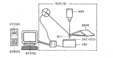
- FIG. 1 is a block diagram of a graphene domain measurement system using AFM friction force mapping according to an embodiment of the present invention.
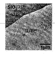
- FIG. 2 is a friction force mapping image measured by an AFM microscope according to an embodiment of the present invention
- Figure 2a is an image measured in the height measurement mode (Topography Mode)
- Figure 2b is an image measured in the friction mode (Friction Mode) .
- FIG. 3 is an image output through the AFM microscope
- Figure 3a is a friction force mapping image output using the friction mode (Friction Mode) according to an embodiment of the present invention
- Figure 3b is a specific portion of the friction force mapping image horizontally cut Graph of frictional force profile.
- FIG. 4 is a continuous graph obtained by plotting a varying friction force ratio while rotating graphene in accordance with one embodiment of the present invention.
- FIG. 5A is a schematic diagram of the corrugation direction of the graphene and the AFM tip advancing direction according to an embodiment of the present invention
- FIG. 5B is a view in which the AFM tip moves in a direction perpendicular to the corrugation direction of graphene
- FIG. 5C is an AFM tip. Drawing to move in the direction coinciding with the corrugation direction of the pin.
- FIG. 6 is a view showing a relationship between the wrinkle direction and the frictional force of the graphene according to an embodiment of the present invention.
- FIG. 7 is a flow chart according to the graphene domain measurement method using AFM friction force mapping according to an embodiment of the present invention.
- the present invention relates to a graphene domain measurement system using AFM friction force mapping and a method thereof, which will be described below with reference to FIGS. 1 to 7.
- FIG. 1 is a block diagram of a graphene domain measurement system using AFM friction force mapping according to an embodiment of the present invention.
- a conventional AFM microscope is used, and an AFM tip 11, a graphene sample 12, and other devices are included.
- the system of the present invention includes a measuring unit 100, an output unit 200, an analysis unit 300, the determination unit 400.
- FIG. 2 is a friction force mapping image measured by an AFM microscope according to an embodiment of the present invention.
- 2A is an image measured in a height measurement mode (Topography Mode)
- FIG. 2B is an image measured in a friction mode (Friction Mode).
- the measuring unit 100 measures the exfoliated graphene sample 12, and the measuring unit is configured by an AFM microscope, and can be measured by setting it to a height measurement mode and a friction mode.
- Topography mode is a mode that can measure the image that can know the height information when measuring graphene
- Friction mode is an image that can know the friction information of each graphene when graphene measurement This mode can be measured.
- Figure 2a is measured in a height measurement mode (Topography Mode), it shows that the height of the substrate SiO 2 and graphene is distinguished.
- Figure 2b is measured in the friction mode (Friction Mode), which shows the difference in friction with the AFM tip 11 as the difference in image contrast.
- the method of measuring the graphene height measurement mode (Topography Mode) and friction mode (Friction Mode) using an AFM microscope is a conventional method, and will not be described in detail.
- the present invention is not merely to measure the graphene, but to determine the wrinkle direction of the graphene, in the method of measuring, using the friction mode of the AFM microscope (Friction Mode) from the initial measurement point Measure while rotating the graphene sample 12 so that the rotation angle to the measurement point is at least 180 °, while maintaining the remaining conditions such as the speed of the graphene sample 12 rotation or the force of the tip pressing the sample. Make a measurement.
- the graphene sample 12 is measured by dividing the sample 12 at least five times at a predetermined angle and rotating (examples of five rotation angles: 0 °, 45 °, 90 °, 135 °, 180 °), to the final measurement point
- the angle of rotation of is based on the initial measurement point, it should be rotated at least 180 °. This will be described later, but to analyze the periodicity of the friction force between the graphene and the AFM tip 11 for 0 to 180 °.
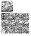
- FIG. 3 is an image output through the AFM microscope
- Figure 3a is a friction force mapping image output using the friction mode (Friction Mode) according to an embodiment of the present invention
- Figure 3b is a specific portion of the friction force mapping image cut horizontally A friction force profile graph for.
- the output unit 200 outputs a frictional force mapping image of the graphene sample 12 using the frictional force mode, and receives frictional force on a specific part of the frictional force mapping image that is horizontally cut in response to a user input signal. Print the profile graph.
- the output unit 200 adjusts the contrast range to the minimum range so as to fit around the graphene sample 12, and outputs a friction force mapping image indicating contrast differences between the respective domains. If the conventional contrast (contrast) range is used, only the difference between the substrate SiO 2 and graphene can be seen, and it is difficult to display the contrast difference between the domains of graphene itself.
- 3A is a friction force mapping image of the friction force information of the graphene sample 12.
- the graphene sample 12 is rotated by dividing the graphene sample 12 at least five times at an angle between 0 ° and 180 °. It is an image output while measuring the pin sample 12.
- each domain is represented by I, II, and III.
- this is merely an embodiment of the present invention and does not necessarily have three domains, but may have one or more domains. However, even if a plurality of domains are measured, the analysis and determination method of the present invention is the same.
- 3B is a friction force profile graph for a specific portion of the friction force mapping image of FIG. 3A which is horizontally cut, and the output unit 200 reads a frictional force signal for the dotted line portion of FIG. 3A and outputs it as a graph.
- the AFM tip 11 moves back and forth to measure the graphene sample 12.
- the relationship between the frictional force and the Y-axis can be graphed.
- the frictional force signal is also changed at a large difference at domain boundaries having different contrasts.
- the analysis unit 300 analyzes the relationship between the advancing direction of the AFM tip 11 and the wrinkle direction of graphene using the friction force profile graph of FIG. 3B.
- the analysis unit 300 first uses the friction force profile graph of FIG. 3B output from the output unit 200 to compare with the friction force signal of each domain based on the friction force signal of the substrate SiO 2 that does not change with rotation. Calculate the ratio. By plotting the X-axis as the rotation angle of the graphene and plotting the ratio of the calculated frictional force as the Y-axis, and plotting each point, a discontinuous graph can be calculated. When connected, a sine type continuous graph having a 180 ° period as shown in FIG. 4 can be obtained.
- the ratio of the frictional force changes with a period of about 180 ° for each domain.
- the contrast difference between domains that is, the contrast difference between domains I, II, and III, is not a characteristic due to hexagonal, which is a structure of graphene, but an AFM tip 11. It can be analyzed by the experiment showing that it is due to the relationship between the advancing direction and the wrinkle direction of the graphene.
- the friction force should be changed at a period of 60 °, but because it is experimentally changed to a period of 180 °, it is wrinkled from north to south It can be related to the wrinkle direction of graphene.
- the signals measured in the friction mode of the AFM also vary according to the wrinkle direction, so that the domains have the same wrinkle direction. Is output as the same signal, and different images are output at domain boundaries with different wrinkle directions.
- 5A is a schematic diagram between the corrugation direction of graphene and the advancing direction of the AFM tip 11 in accordance with an embodiment of the present invention.
- the dotted line direction of the graphene sample 12 is defined as the wrinkle direction of the graphene.
- the AFM tip 11 moves in the a direction
- the AFM tip 11 moves in the direction perpendicular to the wrinkle direction of graphene.
- the AFM tip 11 moves in the b direction
- the AFM tip 11 moves in the direction corresponding to the wrinkle direction of the graphene. Will be measured.
- FIG. 5B shows that the AFM tip 11 moves in the direction perpendicular to the wrinkle direction
- FIG. 5C shows the AFM tip 11 moves in the direction in which the graphene coincides with the wrinkle direction.
- the analysis unit 300 using the friction force profile graph output from the output unit 200, the contrast difference between the domain (I, II, III) of the graphene is the direction of the AFM tip 11 and the The graphene sample 12 is pushed well by the AFM tip 11 when the AFM tip 11 moves in the direction perpendicular to the wrinkle direction.
- the friction force is largely measured between the AFM tip 11 and the graphene, whereas, when the AFM tip 11 is moved in a direction coinciding with the graphene wrinkle direction, the output part is measured by using the point that the friction force is measured small.
- the friction force mapping image output from 200 is analyzed.
- the determination unit 400 uses the information analyzed by the analysis unit 300, and determines the wrinkle direction of graphene through the friction force mapping image.
- the signal measured in the AFM friction mode takes advantage of the fact that the more the resistance is subjected to the AFM tip 11, that is, the greater the magnitude of the friction force, the greater the signal strength. Therefore, the brightest part in the output frictional force mapping image is determined to have the largest frictional force, and the darkest part is the smallest frictional force.
- the wrinkle direction can be inferred from the contrast between the darkest part and the lightest part.
- the difference in contrast is expressed by the angle, the lighter the greater the angle to determine the wrinkle direction of the graphene.
- the domain II is the brightest, so the angle will be the largest. Therefore, the corrugation direction is also determined as the direction close to the direction perpendicular to the traveling direction of the AFM tip 11.
- the darkest part is regarded as coinciding with the advancing direction of the AFM tip 11, and the brightest part is perpendicular to the advancing direction of the AFM tip 11, and then the reference is made to correspond to the angle according to the contrast. Determine the wrinkle direction of graphene.
- FIG. 7 is a flowchart illustrating a graphene domain measurement method using AFM friction force mapping according to an embodiment of the present invention.
- the measurement unit 100 measures the exfoliated graphene sample 12 using an AFM microscope, but measures it using a height measurement mode (Topography Mode) and a friction mode (Friction Mode) (S10). At this time, the measurement unit 100 uses a friction mode of the AFM microscope (Friction Mode), the minimum graphene sample 12 at a predetermined angle so that the rotation angle from the initial measurement point to the final measurement point 180 ° or more Measure by rotating at least 5 times.
- the output unit 200 adjusts the contrast (contrast) to the minimum range to fit around the graphene sample 12, and outputs a friction force mapping image showing the contrast difference between each domain (S20).
- the output unit 200 outputs a friction force profile graph for a specific portion of the friction force mapping image that is laterally cut (S30).
- the analysis unit 300 analyzes the relationship between the traveling direction of the AFM tip 11 and the wrinkle direction of the graphene using the friction force profile graph output in step S30 (S40).
- the determination unit 400 uses the information analyzed in the step S40, but determines the wrinkle direction of the graphene using the contrast difference between each domain through the friction force mapping image output in the step S20. (S50).
- the darkest part of the friction force mapping image output in step S20 is determined to match the traveling direction of the graphene and the traveling direction of the AFM tip 11, and the brightest part is the traveling direction of the graphene and the AFM tip 11.
- the angles are matched according to the contrast difference, and finally the wrinkle direction of the graphene is determined.
Landscapes
- Physics & Mathematics (AREA)
- General Physics & Mathematics (AREA)
- Health & Medical Sciences (AREA)
- General Health & Medical Sciences (AREA)
- Nuclear Medicine, Radiotherapy & Molecular Imaging (AREA)
- Radiology & Medical Imaging (AREA)
- Carbon And Carbon Compounds (AREA)
- Investigating Or Analysing Materials By Optical Means (AREA)
Abstract
La présente invention concerne un système et un procédé de mesure de domaines de graphène mettant en œuvre le mappage du frottement par microscopie à force atomique (AFM), comprenant les étapes consistant à : entraîner en rotation dans le sens des aiguilles d'une montre un échantillon de graphène et le mesurer de manière à ce que l'angle de rotation entre un point de mesure initial et le point de mesure final soit supérieur à 180° ; mesurer à plusieurs reprises le même échantillon de graphène, par exemple au moins cinq fois, tout en l'entraînant en rotation dans le sens des aiguilles d'une montre ; la différence d'ombrage de l'image de mappage de frottement obtenue est liée au sens de progression de la pointe du microscope AFM et au sens des plis du graphène ; obtenir ainsi le sens des plis du graphène. Plus particulièrement, la présente invention comprend les étapes consistant à : mesurer un échantillon de graphène au moyen d'un microscope AFM en mode de mesure du frottement par mise en œuvre d'une unité de mesure ; ajuster une étendue de contraste à la périphérie de l'échantillon de graphène tandis qu'une unité de sortie fournit en sortie une image de mappage du frottement ; mettre en œuvre l'unité de sortie pour fournir en sortie un graphique de profil de frottement concernant une partie spécifique obtenue par coupe de l'image de mappage du frottement ; analyser le rapport entre le sens de progression de la pointe du microscope AFM et le sens des plis du graphène au moyen du graphique de profil de frottement ; et déterminer le sens des plis du graphène en utilisant une différence d'ombrage de contraste entre chaque domaine à travers l'image de mappage du frottement ainsi que les informations analysées par l'unité de détermination.
Priority Applications (1)
| Application Number | Priority Date | Filing Date | Title |
|---|---|---|---|
| CN201280018688.5A CN103477231B (zh) | 2011-05-11 | 2012-05-11 | 利用afm摩擦力映射的石墨烯区域测量系统及其方法 |
Applications Claiming Priority (2)
| Application Number | Priority Date | Filing Date | Title |
|---|---|---|---|
| KR10-2011-0043811 | 2011-05-11 | ||
| KR1020110043811A KR101244383B1 (ko) | 2011-05-11 | 2011-05-11 | Afm 마찰력 매핑을 이용한 그래핀 도메인 측정 시스템 및 그 방법 |
Publications (2)
| Publication Number | Publication Date |
|---|---|
| WO2012154012A2 true WO2012154012A2 (fr) | 2012-11-15 |
| WO2012154012A3 WO2012154012A3 (fr) | 2013-01-17 |
Family
ID=47139839
Family Applications (1)
| Application Number | Title | Priority Date | Filing Date |
|---|---|---|---|
| PCT/KR2012/003730 Ceased WO2012154012A2 (fr) | 2011-05-11 | 2012-05-11 | Système et procédé de mesure de domaines de graphène mettant en œuvre le mappage du frottement par microscopie à force atomique |
Country Status (3)
| Country | Link |
|---|---|
| KR (1) | KR101244383B1 (fr) |
| CN (1) | CN103477231B (fr) |
| WO (1) | WO2012154012A2 (fr) |
Cited By (4)
| Publication number | Priority date | Publication date | Assignee | Title |
|---|---|---|---|---|
| CN103353437A (zh) * | 2013-06-14 | 2013-10-16 | 中国科学院上海微系统与信息技术研究所 | 直观显示金属衬底上cvd石墨烯表面褶皱分布的方法 |
| CN104140092A (zh) * | 2013-05-09 | 2014-11-12 | 国家纳米科学中心 | 一种具有褶皱的石墨烯片层及其制备方法 |
| CN104477886A (zh) * | 2014-11-20 | 2015-04-01 | 中山大学 | 一种褶皱状石墨烯及其可控制备方法 |
| WO2017058700A1 (fr) * | 2015-09-30 | 2017-04-06 | 3M Innovative Properties Company | Système et procédé pour optimiser les interactions corps-objet |
Families Citing this family (7)
| Publication number | Priority date | Publication date | Assignee | Title |
|---|---|---|---|---|
| KR101628557B1 (ko) | 2014-12-05 | 2016-06-08 | 현대자동차주식회사 | 시편 표면의 마찰계수 측정방법 |
| CN106093000A (zh) * | 2016-05-31 | 2016-11-09 | 中山大学 | 一种可拉伸表面增强拉曼活性基底及其制备方法 |
| CN106323866B (zh) * | 2016-08-15 | 2018-10-30 | 清华大学 | 利用石墨烯膜球探针获取异质材料间摩擦系数的方法 |
| KR102119638B1 (ko) | 2018-11-29 | 2020-06-08 | 주식회사 이에스피 | 자율주행차량의 정보활용을 위한 데이터 취득 시스템, 데이터 취득 서버 및 방법 |
| CN109633211B (zh) * | 2019-01-22 | 2021-06-22 | 湘潭大学 | 一种表征二维材料极限剪切应力各向异性的方法 |
| CN110117780B (zh) * | 2019-03-19 | 2021-03-12 | 中国科学院上海微系统与信息技术研究所 | 一种二维材料层及制备方法 |
| KR102386384B1 (ko) * | 2020-07-20 | 2022-04-14 | 서울대학교산학협력단 | 원자힘현미경을 이용한 2차원 전이금속 칼코겐화합물의 결정립계 측정방법 |
Family Cites Families (7)
| Publication number | Priority date | Publication date | Assignee | Title |
|---|---|---|---|---|
| JP2535759B2 (ja) * | 1993-05-13 | 1996-09-18 | 工業技術院長 | 原子間力顕微鏡および原子間力顕微鏡における試料観察方法 |
| JP2852397B2 (ja) * | 1994-11-15 | 1999-02-03 | 工業技術院長 | 原子間力顕微鏡および原子間力顕微鏡における摩擦の解析方法 |
| JP4602284B2 (ja) * | 2006-05-29 | 2010-12-22 | エスアイアイ・ナノテクノロジー株式会社 | 走査型プローブ顕微鏡 |
| KR101622304B1 (ko) * | 2009-08-05 | 2016-05-19 | 삼성전자주식회사 | 그라펜 기재 및 그의 제조방법 |
| JP5410880B2 (ja) * | 2009-08-07 | 2014-02-05 | 株式会社日立ハイテクサイエンス | 摩擦力測定方法および摩擦力測定装置 |
| CN101654243B (zh) * | 2009-08-28 | 2011-11-23 | 青岛大学 | 一种功能纳米石墨烯的制备方法 |
| CN102001650B (zh) * | 2010-12-28 | 2013-05-29 | 上海师范大学 | 冷腔壁条件下化学气相沉积制备石墨烯的方法 |
-
2011
- 2011-05-11 KR KR1020110043811A patent/KR101244383B1/ko not_active Expired - Fee Related
-
2012
- 2012-05-11 CN CN201280018688.5A patent/CN103477231B/zh not_active Expired - Fee Related
- 2012-05-11 WO PCT/KR2012/003730 patent/WO2012154012A2/fr not_active Ceased
Cited By (7)
| Publication number | Priority date | Publication date | Assignee | Title |
|---|---|---|---|---|
| CN104140092A (zh) * | 2013-05-09 | 2014-11-12 | 国家纳米科学中心 | 一种具有褶皱的石墨烯片层及其制备方法 |
| CN104140092B (zh) * | 2013-05-09 | 2017-02-08 | 国家纳米科学中心 | 一种具有褶皱的石墨烯片层及其制备方法 |
| CN103353437A (zh) * | 2013-06-14 | 2013-10-16 | 中国科学院上海微系统与信息技术研究所 | 直观显示金属衬底上cvd石墨烯表面褶皱分布的方法 |
| CN103353437B (zh) * | 2013-06-14 | 2016-08-10 | 中国科学院上海微系统与信息技术研究所 | 直观显示金属衬底上cvd石墨烯表面褶皱分布的方法 |
| CN104477886A (zh) * | 2014-11-20 | 2015-04-01 | 中山大学 | 一种褶皱状石墨烯及其可控制备方法 |
| WO2017058700A1 (fr) * | 2015-09-30 | 2017-04-06 | 3M Innovative Properties Company | Système et procédé pour optimiser les interactions corps-objet |
| US10687753B2 (en) | 2015-09-30 | 2020-06-23 | 3M Innovative Properties Company | System and method for optimizing body and object interactions |
Also Published As
| Publication number | Publication date |
|---|---|
| KR20120126193A (ko) | 2012-11-21 |
| WO2012154012A3 (fr) | 2013-01-17 |
| CN103477231A (zh) | 2013-12-25 |
| KR101244383B1 (ko) | 2013-03-18 |
| CN103477231B (zh) | 2015-06-03 |
Similar Documents
| Publication | Publication Date | Title |
|---|---|---|
| KR101244383B1 (ko) | Afm 마찰력 매핑을 이용한 그래핀 도메인 측정 시스템 및 그 방법 | |
| US20170298429A1 (en) | Graphene transistor gated by charges through a nanopore for bio-molecular sensing and dna sequencing | |
| Rotella et al. | Segmental mobility and glass transition temperature of freely suspended ultrathin polymer membranes | |
| WO2014181203A2 (fr) | Nanofil/nanofeuillet, nanotrou et nanopore intégrés pour séquençage de l'adn et de l'arn | |
| WO2013081268A1 (fr) | Procédé d'auto-étalonnage et caméra à stabilisateur d'image optique (ois) utilisant celui-ci | |
| WO2022237767A1 (fr) | Procédé et appareil de test de stabilité de suspension épaisse de batterie | |
| CN101840078A (zh) | 水波纹级别测试方法 | |
| CN111735714A (zh) | 一种基于光纤的高温全应力-应变曲线测试方法及装置 | |
| CN114518289A (zh) | 一种利用视频采集进行变形应变控的控制方法 | |
| CN1869644A (zh) | 基于微纳界面的现场电化学接触角测量方法 | |
| WO2017209435A1 (fr) | Capteur à haute sensibilité possédant un film mince conducteur transparent qui contient des fissures, et son procédé de préparation | |
| CN208366907U (zh) | 基于二硒化钨的柔性离子传感器 | |
| WO2017204528A1 (fr) | Procédé de prédiction de la forme sans gravité d'une feuille de verre et procédé de gestion de la qualité de la feuille de verre sur base de la forme sans gravité | |
| KR101517429B1 (ko) | 원자간력 현미경을 이용한 그래핀의 두께 측정방법 | |
| WO2009093840A9 (fr) | Procédé et appareil destinés à estimer les caractéristiques de matériaux cibles au moyen d'informations de changement cinétique | |
| CN115356509B (zh) | 一种纠正prc灵敏度的方法及装置 | |
| WO2012071747A1 (fr) | Procédé de détection du point final de gravure d'un métal et détecteur du point final de gravure d'un métal | |
| CN202275053U (zh) | 一种纸张伸缩性自动检测仪 | |
| CN101839865A (zh) | 打印效果自动判别方法 | |
| Wang et al. | Assessing nanofabrication performance based on the estimated Taguchi capability index with subsamples | |
| CN1177192C (zh) | 道路粗糙度检测方法 | |
| CN2548117Y (zh) | 响应式路面平整度检测仪 | |
| CN207300461U (zh) | 一种薄膜应力测试用衬底夹具 | |
| CN115356284B (zh) | 一种基于光谱模型转移的差值补偿方法 | |
| WO2024128850A1 (fr) | Procédé d'inspection des boues d'électrodes |
Legal Events
| Date | Code | Title | Description |
|---|---|---|---|
| 121 | Ep: the epo has been informed by wipo that ep was designated in this application |
Ref document number: 12781599 Country of ref document: EP Kind code of ref document: A2 |
|
| NENP | Non-entry into the national phase |
Ref country code: DE |
|
| 122 | Ep: pct application non-entry in european phase |
Ref document number: 12781599 Country of ref document: EP Kind code of ref document: A2 |