WO2012157013A1 - 電動二輪車、乗物制御装置及び乗物制御方法 - Google Patents
電動二輪車、乗物制御装置及び乗物制御方法 Download PDFInfo
- Publication number
- WO2012157013A1 WO2012157013A1 PCT/JP2011/002666 JP2011002666W WO2012157013A1 WO 2012157013 A1 WO2012157013 A1 WO 2012157013A1 JP 2011002666 W JP2011002666 W JP 2011002666W WO 2012157013 A1 WO2012157013 A1 WO 2012157013A1
- Authority
- WO
- WIPO (PCT)
- Prior art keywords
- cornering
- output
- mode
- normal mode
- electric motor
- Prior art date
- Legal status (The legal status is an assumption and is not a legal conclusion. Google has not performed a legal analysis and makes no representation as to the accuracy of the status listed.)
- Ceased
Links
Images


Classifications
-
- B—PERFORMING OPERATIONS; TRANSPORTING
- B60—VEHICLES IN GENERAL
- B60L—PROPULSION OF ELECTRICALLY-PROPELLED VEHICLES; SUPPLYING ELECTRIC POWER FOR AUXILIARY EQUIPMENT OF ELECTRICALLY-PROPELLED VEHICLES; ELECTRODYNAMIC BRAKE SYSTEMS FOR VEHICLES IN GENERAL; MAGNETIC SUSPENSION OR LEVITATION FOR VEHICLES; MONITORING OPERATING VARIABLES OF ELECTRICALLY-PROPELLED VEHICLES; ELECTRIC SAFETY DEVICES FOR ELECTRICALLY-PROPELLED VEHICLES
- B60L58/00—Methods or circuit arrangements for monitoring or controlling batteries or fuel cells, specially adapted for electric vehicles
- B60L58/10—Methods or circuit arrangements for monitoring or controlling batteries or fuel cells, specially adapted for electric vehicles for monitoring or controlling batteries
- B60L58/12—Methods or circuit arrangements for monitoring or controlling batteries or fuel cells, specially adapted for electric vehicles for monitoring or controlling batteries responding to state of charge [SoC]
-
- B—PERFORMING OPERATIONS; TRANSPORTING
- B60—VEHICLES IN GENERAL
- B60L—PROPULSION OF ELECTRICALLY-PROPELLED VEHICLES; SUPPLYING ELECTRIC POWER FOR AUXILIARY EQUIPMENT OF ELECTRICALLY-PROPELLED VEHICLES; ELECTRODYNAMIC BRAKE SYSTEMS FOR VEHICLES IN GENERAL; MAGNETIC SUSPENSION OR LEVITATION FOR VEHICLES; MONITORING OPERATING VARIABLES OF ELECTRICALLY-PROPELLED VEHICLES; ELECTRIC SAFETY DEVICES FOR ELECTRICALLY-PROPELLED VEHICLES
- B60L15/00—Methods, circuits, or devices for controlling the traction-motor speed of electrically-propelled vehicles
- B60L15/20—Methods, circuits, or devices for controlling the traction-motor speed of electrically-propelled vehicles for control of the vehicle or its driving motor to achieve a desired performance, e.g. speed, torque, programmed variation of speed
- B60L15/2009—Methods, circuits, or devices for controlling the traction-motor speed of electrically-propelled vehicles for control of the vehicle or its driving motor to achieve a desired performance, e.g. speed, torque, programmed variation of speed for braking
-
- B—PERFORMING OPERATIONS; TRANSPORTING
- B60—VEHICLES IN GENERAL
- B60L—PROPULSION OF ELECTRICALLY-PROPELLED VEHICLES; SUPPLYING ELECTRIC POWER FOR AUXILIARY EQUIPMENT OF ELECTRICALLY-PROPELLED VEHICLES; ELECTRODYNAMIC BRAKE SYSTEMS FOR VEHICLES IN GENERAL; MAGNETIC SUSPENSION OR LEVITATION FOR VEHICLES; MONITORING OPERATING VARIABLES OF ELECTRICALLY-PROPELLED VEHICLES; ELECTRIC SAFETY DEVICES FOR ELECTRICALLY-PROPELLED VEHICLES
- B60L15/00—Methods, circuits, or devices for controlling the traction-motor speed of electrically-propelled vehicles
- B60L15/20—Methods, circuits, or devices for controlling the traction-motor speed of electrically-propelled vehicles for control of the vehicle or its driving motor to achieve a desired performance, e.g. speed, torque, programmed variation of speed
- B60L15/2054—Methods, circuits, or devices for controlling the traction-motor speed of electrically-propelled vehicles for control of the vehicle or its driving motor to achieve a desired performance, e.g. speed, torque, programmed variation of speed by controlling transmissions or clutches
-
- B—PERFORMING OPERATIONS; TRANSPORTING
- B60—VEHICLES IN GENERAL
- B60L—PROPULSION OF ELECTRICALLY-PROPELLED VEHICLES; SUPPLYING ELECTRIC POWER FOR AUXILIARY EQUIPMENT OF ELECTRICALLY-PROPELLED VEHICLES; ELECTRODYNAMIC BRAKE SYSTEMS FOR VEHICLES IN GENERAL; MAGNETIC SUSPENSION OR LEVITATION FOR VEHICLES; MONITORING OPERATING VARIABLES OF ELECTRICALLY-PROPELLED VEHICLES; ELECTRIC SAFETY DEVICES FOR ELECTRICALLY-PROPELLED VEHICLES
- B60L3/00—Electric devices on electrically-propelled vehicles for safety purposes; Monitoring operating variables, e.g. speed, deceleration or energy consumption
- B60L3/0023—Detecting, eliminating, remedying or compensating for drive train abnormalities, e.g. failures within the drive train
- B60L3/003—Detecting, eliminating, remedying or compensating for drive train abnormalities, e.g. failures within the drive train relating to inverters
-
- B—PERFORMING OPERATIONS; TRANSPORTING
- B60—VEHICLES IN GENERAL
- B60L—PROPULSION OF ELECTRICALLY-PROPELLED VEHICLES; SUPPLYING ELECTRIC POWER FOR AUXILIARY EQUIPMENT OF ELECTRICALLY-PROPELLED VEHICLES; ELECTRODYNAMIC BRAKE SYSTEMS FOR VEHICLES IN GENERAL; MAGNETIC SUSPENSION OR LEVITATION FOR VEHICLES; MONITORING OPERATING VARIABLES OF ELECTRICALLY-PROPELLED VEHICLES; ELECTRIC SAFETY DEVICES FOR ELECTRICALLY-PROPELLED VEHICLES
- B60L3/00—Electric devices on electrically-propelled vehicles for safety purposes; Monitoring operating variables, e.g. speed, deceleration or energy consumption
- B60L3/0023—Detecting, eliminating, remedying or compensating for drive train abnormalities, e.g. failures within the drive train
- B60L3/0038—Detecting, eliminating, remedying or compensating for drive train abnormalities, e.g. failures within the drive train relating to sensors
-
- B—PERFORMING OPERATIONS; TRANSPORTING
- B60—VEHICLES IN GENERAL
- B60L—PROPULSION OF ELECTRICALLY-PROPELLED VEHICLES; SUPPLYING ELECTRIC POWER FOR AUXILIARY EQUIPMENT OF ELECTRICALLY-PROPELLED VEHICLES; ELECTRODYNAMIC BRAKE SYSTEMS FOR VEHICLES IN GENERAL; MAGNETIC SUSPENSION OR LEVITATION FOR VEHICLES; MONITORING OPERATING VARIABLES OF ELECTRICALLY-PROPELLED VEHICLES; ELECTRIC SAFETY DEVICES FOR ELECTRICALLY-PROPELLED VEHICLES
- B60L3/00—Electric devices on electrically-propelled vehicles for safety purposes; Monitoring operating variables, e.g. speed, deceleration or energy consumption
- B60L3/0023—Detecting, eliminating, remedying or compensating for drive train abnormalities, e.g. failures within the drive train
- B60L3/0061—Detecting, eliminating, remedying or compensating for drive train abnormalities, e.g. failures within the drive train relating to electrical machines
-
- B—PERFORMING OPERATIONS; TRANSPORTING
- B60—VEHICLES IN GENERAL
- B60L—PROPULSION OF ELECTRICALLY-PROPELLED VEHICLES; SUPPLYING ELECTRIC POWER FOR AUXILIARY EQUIPMENT OF ELECTRICALLY-PROPELLED VEHICLES; ELECTRODYNAMIC BRAKE SYSTEMS FOR VEHICLES IN GENERAL; MAGNETIC SUSPENSION OR LEVITATION FOR VEHICLES; MONITORING OPERATING VARIABLES OF ELECTRICALLY-PROPELLED VEHICLES; ELECTRIC SAFETY DEVICES FOR ELECTRICALLY-PROPELLED VEHICLES
- B60L3/00—Electric devices on electrically-propelled vehicles for safety purposes; Monitoring operating variables, e.g. speed, deceleration or energy consumption
- B60L3/04—Cutting off the power supply under fault conditions
-
- B—PERFORMING OPERATIONS; TRANSPORTING
- B60—VEHICLES IN GENERAL
- B60L—PROPULSION OF ELECTRICALLY-PROPELLED VEHICLES; SUPPLYING ELECTRIC POWER FOR AUXILIARY EQUIPMENT OF ELECTRICALLY-PROPELLED VEHICLES; ELECTRODYNAMIC BRAKE SYSTEMS FOR VEHICLES IN GENERAL; MAGNETIC SUSPENSION OR LEVITATION FOR VEHICLES; MONITORING OPERATING VARIABLES OF ELECTRICALLY-PROPELLED VEHICLES; ELECTRIC SAFETY DEVICES FOR ELECTRICALLY-PROPELLED VEHICLES
- B60L50/00—Electric propulsion with power supplied within the vehicle
- B60L50/50—Electric propulsion with power supplied within the vehicle using propulsion power supplied by batteries or fuel cells
- B60L50/51—Electric propulsion with power supplied within the vehicle using propulsion power supplied by batteries or fuel cells characterised by AC-motors
-
- B—PERFORMING OPERATIONS; TRANSPORTING
- B60—VEHICLES IN GENERAL
- B60L—PROPULSION OF ELECTRICALLY-PROPELLED VEHICLES; SUPPLYING ELECTRIC POWER FOR AUXILIARY EQUIPMENT OF ELECTRICALLY-PROPELLED VEHICLES; ELECTRODYNAMIC BRAKE SYSTEMS FOR VEHICLES IN GENERAL; MAGNETIC SUSPENSION OR LEVITATION FOR VEHICLES; MONITORING OPERATING VARIABLES OF ELECTRICALLY-PROPELLED VEHICLES; ELECTRIC SAFETY DEVICES FOR ELECTRICALLY-PROPELLED VEHICLES
- B60L50/00—Electric propulsion with power supplied within the vehicle
- B60L50/50—Electric propulsion with power supplied within the vehicle using propulsion power supplied by batteries or fuel cells
- B60L50/60—Electric propulsion with power supplied within the vehicle using propulsion power supplied by batteries or fuel cells using power supplied by batteries
- B60L50/66—Arrangements of batteries
-
- B—PERFORMING OPERATIONS; TRANSPORTING
- B60—VEHICLES IN GENERAL
- B60L—PROPULSION OF ELECTRICALLY-PROPELLED VEHICLES; SUPPLYING ELECTRIC POWER FOR AUXILIARY EQUIPMENT OF ELECTRICALLY-PROPELLED VEHICLES; ELECTRODYNAMIC BRAKE SYSTEMS FOR VEHICLES IN GENERAL; MAGNETIC SUSPENSION OR LEVITATION FOR VEHICLES; MONITORING OPERATING VARIABLES OF ELECTRICALLY-PROPELLED VEHICLES; ELECTRIC SAFETY DEVICES FOR ELECTRICALLY-PROPELLED VEHICLES
- B60L7/00—Electrodynamic brake systems for vehicles in general
- B60L7/10—Dynamic electric regenerative braking
- B60L7/14—Dynamic electric regenerative braking for vehicles propelled by AC motors
-
- B—PERFORMING OPERATIONS; TRANSPORTING
- B60—VEHICLES IN GENERAL
- B60W—CONJOINT CONTROL OF VEHICLE SUB-UNITS OF DIFFERENT TYPE OR DIFFERENT FUNCTION; CONTROL SYSTEMS SPECIALLY ADAPTED FOR HYBRID VEHICLES; ROAD VEHICLE DRIVE CONTROL SYSTEMS FOR PURPOSES NOT RELATED TO THE CONTROL OF A PARTICULAR SUB-UNIT
- B60W10/00—Conjoint control of vehicle sub-units of different type or different function
- B60W10/04—Conjoint control of vehicle sub-units of different type or different function including control of propulsion units
- B60W10/08—Conjoint control of vehicle sub-units of different type or different function including control of propulsion units including control of electric propulsion units, e.g. motors or generators
-
- B—PERFORMING OPERATIONS; TRANSPORTING
- B60—VEHICLES IN GENERAL
- B60W—CONJOINT CONTROL OF VEHICLE SUB-UNITS OF DIFFERENT TYPE OR DIFFERENT FUNCTION; CONTROL SYSTEMS SPECIALLY ADAPTED FOR HYBRID VEHICLES; ROAD VEHICLE DRIVE CONTROL SYSTEMS FOR PURPOSES NOT RELATED TO THE CONTROL OF A PARTICULAR SUB-UNIT
- B60W10/00—Conjoint control of vehicle sub-units of different type or different function
- B60W10/10—Conjoint control of vehicle sub-units of different type or different function including control of change-speed gearings
-
- B—PERFORMING OPERATIONS; TRANSPORTING
- B62—LAND VEHICLES FOR TRAVELLING OTHERWISE THAN ON RAILS
- B62J—CYCLE SADDLES OR SEATS; AUXILIARY DEVICES OR ACCESSORIES SPECIALLY ADAPTED TO CYCLES AND NOT OTHERWISE PROVIDED FOR, e.g. ARTICLE CARRIERS OR CYCLE PROTECTORS
- B62J43/00—Arrangements of batteries
- B62J43/10—Arrangements of batteries for propulsion
- B62J43/16—Arrangements of batteries for propulsion on motorcycles or the like
-
- B—PERFORMING OPERATIONS; TRANSPORTING
- B62—LAND VEHICLES FOR TRAVELLING OTHERWISE THAN ON RAILS
- B62J—CYCLE SADDLES OR SEATS; AUXILIARY DEVICES OR ACCESSORIES SPECIALLY ADAPTED TO CYCLES AND NOT OTHERWISE PROVIDED FOR, e.g. ARTICLE CARRIERS OR CYCLE PROTECTORS
- B62J45/00—Electrical equipment arrangements specially adapted for use as accessories on cycles, not otherwise provided for
- B62J45/20—Cycle computers as cycle accessories
-
- B—PERFORMING OPERATIONS; TRANSPORTING
- B62—LAND VEHICLES FOR TRAVELLING OTHERWISE THAN ON RAILS
- B62K—CYCLES; CYCLE FRAMES; CYCLE STEERING DEVICES; RIDER-OPERATED TERMINAL CONTROLS SPECIALLY ADAPTED FOR CYCLES; CYCLE AXLE SUSPENSIONS; CYCLE SIDECARS, FORECARS, OR THE LIKE
- B62K11/00—Motorcycles, engine-assisted cycles or motor scooters with one or two wheels
- B62K11/02—Frames
- B62K11/04—Frames characterised by the engine being between front and rear wheels
- B62K11/06—Frames characterised by the engine being between front and rear wheels the frame being of single-beam type
-
- B—PERFORMING OPERATIONS; TRANSPORTING
- B62—LAND VEHICLES FOR TRAVELLING OTHERWISE THAN ON RAILS
- B62K—CYCLES; CYCLE FRAMES; CYCLE STEERING DEVICES; RIDER-OPERATED TERMINAL CONTROLS SPECIALLY ADAPTED FOR CYCLES; CYCLE AXLE SUSPENSIONS; CYCLE SIDECARS, FORECARS, OR THE LIKE
- B62K25/00—Axle suspensions
- B62K25/04—Axle suspensions for mounting axles resiliently on cycle frame or fork
- B62K25/28—Axle suspensions for mounting axles resiliently on cycle frame or fork with pivoted chain-stay
- B62K25/283—Axle suspensions for mounting axles resiliently on cycle frame or fork with pivoted chain-stay for cycles without a pedal crank, e.g. motorcycles
-
- B—PERFORMING OPERATIONS; TRANSPORTING
- B60—VEHICLES IN GENERAL
- B60L—PROPULSION OF ELECTRICALLY-PROPELLED VEHICLES; SUPPLYING ELECTRIC POWER FOR AUXILIARY EQUIPMENT OF ELECTRICALLY-PROPELLED VEHICLES; ELECTRODYNAMIC BRAKE SYSTEMS FOR VEHICLES IN GENERAL; MAGNETIC SUSPENSION OR LEVITATION FOR VEHICLES; MONITORING OPERATING VARIABLES OF ELECTRICALLY-PROPELLED VEHICLES; ELECTRIC SAFETY DEVICES FOR ELECTRICALLY-PROPELLED VEHICLES
- B60L2200/00—Type of vehicles
- B60L2200/12—Bikes
-
- B—PERFORMING OPERATIONS; TRANSPORTING
- B60—VEHICLES IN GENERAL
- B60L—PROPULSION OF ELECTRICALLY-PROPELLED VEHICLES; SUPPLYING ELECTRIC POWER FOR AUXILIARY EQUIPMENT OF ELECTRICALLY-PROPELLED VEHICLES; ELECTRODYNAMIC BRAKE SYSTEMS FOR VEHICLES IN GENERAL; MAGNETIC SUSPENSION OR LEVITATION FOR VEHICLES; MONITORING OPERATING VARIABLES OF ELECTRICALLY-PROPELLED VEHICLES; ELECTRIC SAFETY DEVICES FOR ELECTRICALLY-PROPELLED VEHICLES
- B60L2200/00—Type of vehicles
- B60L2200/32—Waterborne vessels
-
- B—PERFORMING OPERATIONS; TRANSPORTING
- B60—VEHICLES IN GENERAL
- B60L—PROPULSION OF ELECTRICALLY-PROPELLED VEHICLES; SUPPLYING ELECTRIC POWER FOR AUXILIARY EQUIPMENT OF ELECTRICALLY-PROPELLED VEHICLES; ELECTRODYNAMIC BRAKE SYSTEMS FOR VEHICLES IN GENERAL; MAGNETIC SUSPENSION OR LEVITATION FOR VEHICLES; MONITORING OPERATING VARIABLES OF ELECTRICALLY-PROPELLED VEHICLES; ELECTRIC SAFETY DEVICES FOR ELECTRICALLY-PROPELLED VEHICLES
- B60L2240/00—Control parameters of input or output; Target parameters
- B60L2240/10—Vehicle control parameters
- B60L2240/12—Speed
-
- B—PERFORMING OPERATIONS; TRANSPORTING
- B60—VEHICLES IN GENERAL
- B60L—PROPULSION OF ELECTRICALLY-PROPELLED VEHICLES; SUPPLYING ELECTRIC POWER FOR AUXILIARY EQUIPMENT OF ELECTRICALLY-PROPELLED VEHICLES; ELECTRODYNAMIC BRAKE SYSTEMS FOR VEHICLES IN GENERAL; MAGNETIC SUSPENSION OR LEVITATION FOR VEHICLES; MONITORING OPERATING VARIABLES OF ELECTRICALLY-PROPELLED VEHICLES; ELECTRIC SAFETY DEVICES FOR ELECTRICALLY-PROPELLED VEHICLES
- B60L2240/00—Control parameters of input or output; Target parameters
- B60L2240/10—Vehicle control parameters
- B60L2240/24—Steering angle
-
- B—PERFORMING OPERATIONS; TRANSPORTING
- B60—VEHICLES IN GENERAL
- B60L—PROPULSION OF ELECTRICALLY-PROPELLED VEHICLES; SUPPLYING ELECTRIC POWER FOR AUXILIARY EQUIPMENT OF ELECTRICALLY-PROPELLED VEHICLES; ELECTRODYNAMIC BRAKE SYSTEMS FOR VEHICLES IN GENERAL; MAGNETIC SUSPENSION OR LEVITATION FOR VEHICLES; MONITORING OPERATING VARIABLES OF ELECTRICALLY-PROPELLED VEHICLES; ELECTRIC SAFETY DEVICES FOR ELECTRICALLY-PROPELLED VEHICLES
- B60L2240/00—Control parameters of input or output; Target parameters
- B60L2240/40—Drive Train control parameters
- B60L2240/42—Drive Train control parameters related to electric machines
- B60L2240/421—Speed
-
- B—PERFORMING OPERATIONS; TRANSPORTING
- B60—VEHICLES IN GENERAL
- B60L—PROPULSION OF ELECTRICALLY-PROPELLED VEHICLES; SUPPLYING ELECTRIC POWER FOR AUXILIARY EQUIPMENT OF ELECTRICALLY-PROPELLED VEHICLES; ELECTRODYNAMIC BRAKE SYSTEMS FOR VEHICLES IN GENERAL; MAGNETIC SUSPENSION OR LEVITATION FOR VEHICLES; MONITORING OPERATING VARIABLES OF ELECTRICALLY-PROPELLED VEHICLES; ELECTRIC SAFETY DEVICES FOR ELECTRICALLY-PROPELLED VEHICLES
- B60L2240/00—Control parameters of input or output; Target parameters
- B60L2240/40—Drive Train control parameters
- B60L2240/42—Drive Train control parameters related to electric machines
- B60L2240/423—Torque
-
- B—PERFORMING OPERATIONS; TRANSPORTING
- B60—VEHICLES IN GENERAL
- B60L—PROPULSION OF ELECTRICALLY-PROPELLED VEHICLES; SUPPLYING ELECTRIC POWER FOR AUXILIARY EQUIPMENT OF ELECTRICALLY-PROPELLED VEHICLES; ELECTRODYNAMIC BRAKE SYSTEMS FOR VEHICLES IN GENERAL; MAGNETIC SUSPENSION OR LEVITATION FOR VEHICLES; MONITORING OPERATING VARIABLES OF ELECTRICALLY-PROPELLED VEHICLES; ELECTRIC SAFETY DEVICES FOR ELECTRICALLY-PROPELLED VEHICLES
- B60L2240/00—Control parameters of input or output; Target parameters
- B60L2240/40—Drive Train control parameters
- B60L2240/42—Drive Train control parameters related to electric machines
- B60L2240/425—Temperature
-
- B—PERFORMING OPERATIONS; TRANSPORTING
- B60—VEHICLES IN GENERAL
- B60L—PROPULSION OF ELECTRICALLY-PROPELLED VEHICLES; SUPPLYING ELECTRIC POWER FOR AUXILIARY EQUIPMENT OF ELECTRICALLY-PROPELLED VEHICLES; ELECTRODYNAMIC BRAKE SYSTEMS FOR VEHICLES IN GENERAL; MAGNETIC SUSPENSION OR LEVITATION FOR VEHICLES; MONITORING OPERATING VARIABLES OF ELECTRICALLY-PROPELLED VEHICLES; ELECTRIC SAFETY DEVICES FOR ELECTRICALLY-PROPELLED VEHICLES
- B60L2240/00—Control parameters of input or output; Target parameters
- B60L2240/40—Drive Train control parameters
- B60L2240/48—Drive Train control parameters related to transmissions
- B60L2240/486—Operating parameters
-
- B—PERFORMING OPERATIONS; TRANSPORTING
- B60—VEHICLES IN GENERAL
- B60L—PROPULSION OF ELECTRICALLY-PROPELLED VEHICLES; SUPPLYING ELECTRIC POWER FOR AUXILIARY EQUIPMENT OF ELECTRICALLY-PROPELLED VEHICLES; ELECTRODYNAMIC BRAKE SYSTEMS FOR VEHICLES IN GENERAL; MAGNETIC SUSPENSION OR LEVITATION FOR VEHICLES; MONITORING OPERATING VARIABLES OF ELECTRICALLY-PROPELLED VEHICLES; ELECTRIC SAFETY DEVICES FOR ELECTRICALLY-PROPELLED VEHICLES
- B60L2240/00—Control parameters of input or output; Target parameters
- B60L2240/40—Drive Train control parameters
- B60L2240/50—Drive Train control parameters related to clutches
- B60L2240/507—Operating parameters
-
- B—PERFORMING OPERATIONS; TRANSPORTING
- B60—VEHICLES IN GENERAL
- B60L—PROPULSION OF ELECTRICALLY-PROPELLED VEHICLES; SUPPLYING ELECTRIC POWER FOR AUXILIARY EQUIPMENT OF ELECTRICALLY-PROPELLED VEHICLES; ELECTRODYNAMIC BRAKE SYSTEMS FOR VEHICLES IN GENERAL; MAGNETIC SUSPENSION OR LEVITATION FOR VEHICLES; MONITORING OPERATING VARIABLES OF ELECTRICALLY-PROPELLED VEHICLES; ELECTRIC SAFETY DEVICES FOR ELECTRICALLY-PROPELLED VEHICLES
- B60L2240/00—Control parameters of input or output; Target parameters
- B60L2240/40—Drive Train control parameters
- B60L2240/52—Drive Train control parameters related to converters
- B60L2240/525—Temperature of converter or components thereof
-
- B—PERFORMING OPERATIONS; TRANSPORTING
- B60—VEHICLES IN GENERAL
- B60L—PROPULSION OF ELECTRICALLY-PROPELLED VEHICLES; SUPPLYING ELECTRIC POWER FOR AUXILIARY EQUIPMENT OF ELECTRICALLY-PROPELLED VEHICLES; ELECTRODYNAMIC BRAKE SYSTEMS FOR VEHICLES IN GENERAL; MAGNETIC SUSPENSION OR LEVITATION FOR VEHICLES; MONITORING OPERATING VARIABLES OF ELECTRICALLY-PROPELLED VEHICLES; ELECTRIC SAFETY DEVICES FOR ELECTRICALLY-PROPELLED VEHICLES
- B60L2240/00—Control parameters of input or output; Target parameters
- B60L2240/40—Drive Train control parameters
- B60L2240/54—Drive Train control parameters related to batteries
- B60L2240/545—Temperature
-
- B—PERFORMING OPERATIONS; TRANSPORTING
- B60—VEHICLES IN GENERAL
- B60L—PROPULSION OF ELECTRICALLY-PROPELLED VEHICLES; SUPPLYING ELECTRIC POWER FOR AUXILIARY EQUIPMENT OF ELECTRICALLY-PROPELLED VEHICLES; ELECTRODYNAMIC BRAKE SYSTEMS FOR VEHICLES IN GENERAL; MAGNETIC SUSPENSION OR LEVITATION FOR VEHICLES; MONITORING OPERATING VARIABLES OF ELECTRICALLY-PROPELLED VEHICLES; ELECTRIC SAFETY DEVICES FOR ELECTRICALLY-PROPELLED VEHICLES
- B60L2240/00—Control parameters of input or output; Target parameters
- B60L2240/40—Drive Train control parameters
- B60L2240/54—Drive Train control parameters related to batteries
- B60L2240/547—Voltage
-
- B—PERFORMING OPERATIONS; TRANSPORTING
- B60—VEHICLES IN GENERAL
- B60L—PROPULSION OF ELECTRICALLY-PROPELLED VEHICLES; SUPPLYING ELECTRIC POWER FOR AUXILIARY EQUIPMENT OF ELECTRICALLY-PROPELLED VEHICLES; ELECTRODYNAMIC BRAKE SYSTEMS FOR VEHICLES IN GENERAL; MAGNETIC SUSPENSION OR LEVITATION FOR VEHICLES; MONITORING OPERATING VARIABLES OF ELECTRICALLY-PROPELLED VEHICLES; ELECTRIC SAFETY DEVICES FOR ELECTRICALLY-PROPELLED VEHICLES
- B60L2240/00—Control parameters of input or output; Target parameters
- B60L2240/40—Drive Train control parameters
- B60L2240/54—Drive Train control parameters related to batteries
- B60L2240/549—Current
-
- B—PERFORMING OPERATIONS; TRANSPORTING
- B60—VEHICLES IN GENERAL
- B60L—PROPULSION OF ELECTRICALLY-PROPELLED VEHICLES; SUPPLYING ELECTRIC POWER FOR AUXILIARY EQUIPMENT OF ELECTRICALLY-PROPELLED VEHICLES; ELECTRODYNAMIC BRAKE SYSTEMS FOR VEHICLES IN GENERAL; MAGNETIC SUSPENSION OR LEVITATION FOR VEHICLES; MONITORING OPERATING VARIABLES OF ELECTRICALLY-PROPELLED VEHICLES; ELECTRIC SAFETY DEVICES FOR ELECTRICALLY-PROPELLED VEHICLES
- B60L2250/00—Driver interactions
- B60L2250/24—Driver interactions by lever actuation
-
- B—PERFORMING OPERATIONS; TRANSPORTING
- B60—VEHICLES IN GENERAL
- B60L—PROPULSION OF ELECTRICALLY-PROPELLED VEHICLES; SUPPLYING ELECTRIC POWER FOR AUXILIARY EQUIPMENT OF ELECTRICALLY-PROPELLED VEHICLES; ELECTRODYNAMIC BRAKE SYSTEMS FOR VEHICLES IN GENERAL; MAGNETIC SUSPENSION OR LEVITATION FOR VEHICLES; MONITORING OPERATING VARIABLES OF ELECTRICALLY-PROPELLED VEHICLES; ELECTRIC SAFETY DEVICES FOR ELECTRICALLY-PROPELLED VEHICLES
- B60L2260/00—Operating Modes
- B60L2260/20—Drive modes; Transition between modes
- B60L2260/28—Four wheel or all wheel drive
-
- B—PERFORMING OPERATIONS; TRANSPORTING
- B62—LAND VEHICLES FOR TRAVELLING OTHERWISE THAN ON RAILS
- B62K—CYCLES; CYCLE FRAMES; CYCLE STEERING DEVICES; RIDER-OPERATED TERMINAL CONTROLS SPECIALLY ADAPTED FOR CYCLES; CYCLE AXLE SUSPENSIONS; CYCLE SIDECARS, FORECARS, OR THE LIKE
- B62K2204/00—Adaptations for driving cycles by electric motor
-
- Y—GENERAL TAGGING OF NEW TECHNOLOGICAL DEVELOPMENTS; GENERAL TAGGING OF CROSS-SECTIONAL TECHNOLOGIES SPANNING OVER SEVERAL SECTIONS OF THE IPC; TECHNICAL SUBJECTS COVERED BY FORMER USPC CROSS-REFERENCE ART COLLECTIONS [XRACs] AND DIGESTS
- Y02—TECHNOLOGIES OR APPLICATIONS FOR MITIGATION OR ADAPTATION AGAINST CLIMATE CHANGE
- Y02T—CLIMATE CHANGE MITIGATION TECHNOLOGIES RELATED TO TRANSPORTATION
- Y02T10/00—Road transport of goods or passengers
- Y02T10/60—Other road transportation technologies with climate change mitigation effect
- Y02T10/64—Electric machine technologies in electromobility
-
- Y—GENERAL TAGGING OF NEW TECHNOLOGICAL DEVELOPMENTS; GENERAL TAGGING OF CROSS-SECTIONAL TECHNOLOGIES SPANNING OVER SEVERAL SECTIONS OF THE IPC; TECHNICAL SUBJECTS COVERED BY FORMER USPC CROSS-REFERENCE ART COLLECTIONS [XRACs] AND DIGESTS
- Y02—TECHNOLOGIES OR APPLICATIONS FOR MITIGATION OR ADAPTATION AGAINST CLIMATE CHANGE
- Y02T—CLIMATE CHANGE MITIGATION TECHNOLOGIES RELATED TO TRANSPORTATION
- Y02T10/00—Road transport of goods or passengers
- Y02T10/60—Other road transportation technologies with climate change mitigation effect
- Y02T10/70—Energy storage systems for electromobility, e.g. batteries
-
- Y—GENERAL TAGGING OF NEW TECHNOLOGICAL DEVELOPMENTS; GENERAL TAGGING OF CROSS-SECTIONAL TECHNOLOGIES SPANNING OVER SEVERAL SECTIONS OF THE IPC; TECHNICAL SUBJECTS COVERED BY FORMER USPC CROSS-REFERENCE ART COLLECTIONS [XRACs] AND DIGESTS
- Y02—TECHNOLOGIES OR APPLICATIONS FOR MITIGATION OR ADAPTATION AGAINST CLIMATE CHANGE
- Y02T—CLIMATE CHANGE MITIGATION TECHNOLOGIES RELATED TO TRANSPORTATION
- Y02T10/00—Road transport of goods or passengers
- Y02T10/60—Other road transportation technologies with climate change mitigation effect
- Y02T10/72—Electric energy management in electromobility
Definitions
- the present invention relates to an electric motorcycle, a vehicle control device, and a vehicle control method in which an operation mode shifts according to a state value.
- the motor output may be changed based on information different from the operation command. For example, in order to prevent the motor temperature and inverter temperature from becoming too high, to protect the battery and technology to shift to the output limit mode that temporarily limits the motor output when those temperatures exceed the allowable range.
- the battery temperature exceeds the allowable range or when the battery voltage falls below the allowable range there is a technology for temporarily limiting the battery output and shifting to the output limiting mode for limiting the motor output. (For example, refer to Patent Document 1).
- the control is performed to return from the output restriction mode to the normal mode.
- the driving power will fluctuate during cornering where the driver becomes nervous. It will make the ring worse.
- the vehicle body is banked at the time of cornering, so the influence on the driving feeling becomes large.
- an object of the present invention is to improve driving feeling during cornering in a vehicle in which an operation mode shifts according to a state value other than an operation command.
- the present invention has been made in view of the above circumstances, and the electric motorcycle according to the present invention is capable of detecting a driving command detection means for detecting a driving command from a driver and a state value different from the driving command.
- a value detection means, an electric motor for generating driving power transmitted to the drive wheels, a normal mode for controlling the output of the electric motor in accordance with the operation command detected by the operation command detection means, and the electric motor Can be executed in a non-normal mode that makes the output of the normal mode different from the normal mode, and the state value detected by the state value detecting means in one of the normal mode and the non-normal mode is a predetermined value.
- the control means for shifting to the other mode of the normal mode and the non-normal mode and the electric motorcycle is cornering. Cornering determining means, and the control means determines that the electric motorcycle is not cornering by the cornering determining means when the cornering determining means determines that the electric motorcycle is cornering and the transition condition is satisfied. The output change of the electric motor is suppressed more than when the determination is made and the transition condition is satisfied.
- the electric motor when it is determined that cornering is being performed and the transition condition is satisfied, the electric motor is controlled so as to suppress the output change, so that a large change in traveling power during cornering is suppressed. . Therefore, it is possible to improve the driving feeling during cornering in an electric motorcycle in which the operation mode shifts according to a state value other than the operation command.
- “suppress output change” means that mode change is prohibited to prevent output change accompanying mode change, and mode change is performed while keeping the output change accompanying mode change smaller than during non-cornering. It means to include.
- the control unit shifts from one mode to the other mode of the normal mode and the non-normal mode. It may be prohibited.
- the mode transition is prohibited, so that the output fluctuation of the electric motor accompanying the mode transition can be prevented. Therefore, the driving feeling during cornering can be improved easily and reliably.
- the control means determines that the electric motorcycle is not cornering and the transition condition is satisfied. Instead of this, at least one of the amount of change in the output of the electric motor and the time change rate when shifting from one mode to the other mode of the normal mode and the non-normal mode may be reduced.
- At least one state of drive system electrical equipment is detected as the state value, and the transition condition is a condition for shifting from the normal mode to the non-normal mode, and the state value is a predetermined non-normal value.
- the means may reduce the output of the electric motor in the non-normal mode compared to the output of the electric motor in the normal mode.
- the drive system electrical device when the state of the drive system electrical device in the normal mode becomes the non-normal state, the drive system electrical device is protected by shifting to the non-normal mode and reducing the output of the electric motor. it can.
- a battery for supplying electric power to the electric motor, and an inverter interposed between the battery and the electric motor, and the state value detecting means includes the battery, the inverter, and the electric motor.
- a temperature sensor for detecting at least one temperature as the state value a battery sensor for detecting the discharge capacity of the battery as the state value, a rotation speed sensor for detecting the rotation speed of the electric motor as the state value, and a traveling speed. It includes at least one of a vehicle speed sensor that is detected as the state value, and an abnormality detection unit that detects an abnormality of the sensor that detects input information for controlling the electric motor as the state value, and the transition condition is The condition that the temperature detected by the temperature sensor exceeds a predetermined allowable value, and the release detected by the battery sensor.
- An output restriction mode for reducing the output of the electric motor may be provided, and the control unit may shift to the output restriction mode when the output restriction mode transition condition is satisfied in the normal mode.
- the control means determines from the state in which the cornering determination means determines that the electric motorcycle is cornering and the change condition is satisfied so that the change in the output of the electric motor is suppressed.
- the target value of the output of the electric motor may be controlled to gradually approach the target value after the mode transition.
- the target value of the motor output is gradually brought closer to the target value after the mode transition, so that the mode is maintained while maintaining a good driving feeling.
- the migration can be completed.
- the transition condition has a predetermined output rapid increase mode transition condition, and the non-normal mode is the normal mode when an increase rate of the accelerator operation amount detected by the operation command detection means is equal to or greater than a predetermined threshold.
- the control unit may shift to the output rapid increase mode when the output rapid increase mode transition condition is satisfied in the normal mode.
- the motor output is temporarily increased as compared to when the accelerator operation amount suddenly increases in the normal mode, so instantaneously larger acceleration than usual is generated.
- the acceleration response experienced by the driver can be improved.
- Cornering state determining means for determining whether or not the running state is an end of cornering, and the control means determines the cornering when the cornering state determining means determines that the running state is the end of cornering. Even if it is determined by the determining means that the electric motorcycle is cornering and the output sudden increase mode transition condition is satisfied, the output change of the electric motor need not be suppressed.
- Notification means for notifying a driver and the control means suppresses a change in output of the electric motor when the cornering judgment means judges that the electric motorcycle is cornering and the transition condition is satisfied.
- the driver may be notified by the notification means.
- the driver since the driver is notified that the output change of the electric motor is being suppressed, the driver can grasp the control state of the vehicle.
- the control means may change the degree of suppression of the output change of the electric motor according to the vehicle operating state during cornering.
- the degree of suppression of the change in the output of the electric motor is adjusted in accordance with the vehicle driving state during cornering, so that both the control effect due to mode transition and the improvement of driving feeling during cornering are preferably achieved. It becomes possible to do.
- the vehicle control device includes a driving command receiving unit that receives a driving command from a driver, a state value receiving unit that can receive a state value different from the driving command, and a vehicle that travels according to the driving command.
- the normal mode execution unit that controls the output of the drive source
- the non-normal mode execution unit that makes the output of the traveling drive source different from the normal mode
- a mode transition control unit that shifts to the other mode of the normal mode and the non-normal mode, and whether the vehicle is cornering
- a cornering determination unit that determines whether the vehicle is cornering by the cornering determination unit and the transition condition Enacted in the case, than when the vehicle is and the shift condition is determined not to be in cornering is satisfied in the cornering decision unit inhibits the output change of the drive source.
- the vehicle control method includes a driving command receiving step for receiving a driving command from a driver, a state value receiving step capable of receiving a state value different from the driving command, and traveling according to the driving command.
- the normal mode execution step for controlling the output of the drive source
- the non-normal mode execution step for making the output of the travel drive source different from the normal mode, and the normal mode and the non-normal mode in the one mode
- a mode transition control step for transitioning to the other mode of the normal mode and the non-normal mode when a predetermined transition condition is established for the state value
- a cornering determination step for determining whether or not the vehicle is cornering
- the cornering determination unit determines that the vehicle is cornering and the transition condition is satisfied. The, than when the vehicle is and the shift condition is determined not to be in cornering is satisfied in the cornering decision unit inhibits the output change of the drive source.
- FIG. 1 is a right side view of an electric motorcycle according to an embodiment of the present invention.
- FIG. 2 is a block diagram illustrating a control system for the electric motorcycle shown in FIG. 1.
- Fig. 3 is a flowchart for explaining control of the electric motorcycle shown in Fig. 2. It is a flowchart explaining the output restriction
- FIG. 9 is a graph corresponding to FIG. 8 of a first modified example relating to output restriction mode transition.
- FIG. 9 is a graph corresponding to FIG. 8 of a second modified example regarding output restriction mode transition.
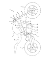
- FIG. 1 is a right side view of an electric motorcycle 1 (vehicle) according to an embodiment of the present invention.
- the electric motorcycle 1 includes a front wheel 2 that is a driven wheel and a rear wheel 3 that is a drive wheel.
- the front wheel 2 is rotatably supported at the lower ends of a pair of left and right front forks 4 that extend substantially vertically, and the upper portion of the front fork 4 is a steering shaft (not shown) via a pair of upper and lower brackets 4a and 4b. ) Is supported.
- the steering shaft is rotatably supported in a state of being inserted into the head pipe 5 on the vehicle body side, and a bar-type handle 6 extending left and right is attached to the upper bracket 4b.
- the front wheel 2 can be steered by rotating the left and right.
- An accelerator grip 7 is provided on the right side of the handle 6 so as to be gripped by the right hand of the driver and rotated by twisting of the wrist, and a brake lever 8 is provided on the front side of the accelerator grip 7.
- a fixed grip (not shown) that is gripped by the driver's left hand is provided on the left side of the handle 6, and a clutch lever (not shown) is provided on the front side of the fixed grip.
- the body frame of the electric motorcycle 1 is provided with a pair of main frames 9 that are separated from the head pipe 5 on the left and right sides and slightly inclined downward toward the rear while extending substantially linearly in side view.
- a pair of left and right down frames 10 extending downward therefrom is connected to the front end portion of the main frame 9.
- An upper portion of a frame-like pivot frame 11 is provided at the rear end portion of the main frame 9.
- a rear portion of the case 13 of the power plant 12 is fastened to the pivot frame 11, and a front portion of the case 13 is fastened to a lower end portion of the down frame 10.
- the pivot frame 11 supports a front end portion of a swing arm 14 that supports the rear wheel 3 so as to swing up and down.
- a rear suspension 15 is interposed between the intermediate portion of the swing arm 14 and the rear end portion of the main frame 9.
- a seat 16 for riding is disposed above the swing arm 14, and this seat 16 is supported by a rear frame (not shown) connected to the main frame 9.
- a dummy tank 17 is provided in front of the seat 16 so that the driver can hold it between his knees.
- the case 13 of the power plant 12 includes an electric motor 18 that generates traveling power, a transmission 19 for shifting rotational power from the electric motor 18 and transmitting it to the rear wheels 3, and an electric motor 18 and a transmission 19.
- a clutch 20 that connects or disconnects the power transmission therebetween is housed.
- a battery 21 for supplying electric power to the electric motor 18 is disposed above the front side of the case 13 of the power plant 12. Above the rear side of the case 13 of the power plant 12, the DC power of the battery 21 is converted into AC power and supplied to the electric motor 18, or AC power (regenerative power) generated using the electric motor 18 as a generator is DC power.
- An inverter 22 is provided that converts the power into the battery 21 and charges the battery 21.
- An ECU 23 vehicle control device, which will be described in detail later, is disposed between the pair of left and right main frames 9.
- the electric motor 18, the battery 21, and the inverter 22 are referred to as drive system electric devices.
- FIG. 2 is a block diagram illustrating a control system of the electric motorcycle 1 shown in FIG.
- the ECU 23 is connected with various sensors 30 to 41 as inputs.
- the motor temperature sensor 30, the inverter temperature sensor 31, and the battery temperature sensor 32 detect the temperatures of the electric motor 18, the inverter 22, and the battery 21, respectively.
- the battery voltage sensor 33 detects the output voltage of the battery 21, and the battery remaining amount sensor 34 detects the remaining amount of the battery 21. In other words, the battery voltage sensor 33 and the battery remaining amount sensor 34 detect the discharge capacity of the battery 21.
- the rotation speed sensor 35 detects the rotation speed of the electric motor 18.
- the vehicle speed sensor 36 detects the traveling speed of the electric motorcycle 1, and for example, a front wheel speed sensor that detects the rotation speed of the front wheel 2 that is a driven wheel is used.
- the accelerator operation amount sensor 37 detects the operation amount (opening degree) of the accelerator grip 7.
- the brake sensor 38 detects an operation amount (braking amount) of the brake lever 8.
- the clutch switch 39 detects whether the clutch 20 is in a connected state or a disconnected state.
- the gear position sensor 40 detects the position (reduction ratio) of the transmission gear of the transmission 19.
- the bank angle sensor 41 detects a vehicle body inclination angle when the vehicle body of the electric motorcycle 1 is inclined in the lateral direction from the upright state.
- the ECU 23 includes a sensor abnormality detection unit 45, a state value reception unit 46, a transition condition determination unit 47, an operation command reception unit 48, a cornering determination unit 49, a mode transition control unit 50, a normal mode execution unit 51, and an output restriction mode execution unit 52.
- the regenerative mode execution unit 53 and the output rapid increase mode execution unit 54 are provided.
- the sensor abnormality detection unit 45 detects abnormality of various sensors 30 to 41 that detect input information for controlling the electric motor 18. For example, a pair of sensors 30 to 41 are provided, and the sensor abnormality detection unit 45 detects that the sensors are normal when the values detected from the pair of sensors 30 to 41 are the same, and different from each other. Detects that the sensor is abnormal.
- the state value receiving unit 46 includes a motor temperature sensor 30, an inverter temperature sensor 31, a battery temperature sensor 32, a battery voltage sensor 33, a battery remaining amount sensor 34, a rotation speed sensor 35, a vehicle speed sensor 36, a sensor abnormality detection unit 45, and the like.
- a signal is received, and a state value that is not an operation command is received. That is, in this embodiment, the motor temperature sensor 30, the inverter temperature sensor 31, the battery temperature sensor 32, the battery voltage sensor 33, the battery remaining amount sensor 34, the rotation speed sensor 35, the vehicle speed sensor 36, and the sensor abnormality detection unit 45 are in the state values.
- the detection means is configured.
- the state value means a value related to the state of the in-vehicle device that changes even without a driving command from the driver
- the driving command means an accelerator operation amount, a brake operation amount, a clutch operation state, a transmission gear, This means a command for the driver to change the traveling state of the electric motorcycle 1 such as a position.
- the transition condition determination unit 47 performs mode transition between the normal mode and the non-normal mode (output restriction mode, regeneration mode, output rapid increase mode) that outputs a driving force different from the normal mode. It is determined whether or not a state value received by the state value receiving unit 46 satisfies a predetermined transition condition.
- the driving command receiving unit 48 receives signals from the accelerator operation amount sensor 37, the brake sensor 38, the clutch switch 39, the gear position sensor 40, and the like, and receives a driving command from the driver. That is, in the present embodiment, at least one of the accelerator operation amount sensor 37, the brake sensor 38, the clutch switch 39, and the gear position sensor 40 constitutes an operation command detection means.
- the cornering determination unit 49 determines whether or not the electric motorcycle 1 is cornering. For example, the cornering determination unit 49 determines that the electric motorcycle 1 is cornering when the inclination angle from the upright state of the vehicle body detected by the bank angle sensor 41 is a predetermined angle or more.
- the mode transition control unit 50 is based on the determination result in the transition condition determination unit 47 and the determination result in the cornering determination unit 49 between each operation mode (normal mode, output limit mode, regeneration mode, output rapid increase mode). Control mode transition. Further, the electric motorcycle 1 includes a notification device 55 that notifies the driver of information by display such as lighting of a lamp or sound by a speaker, etc., and the mode transition control unit 50 is in the process of establishing transition conditions as will be described later. Nevertheless, when the mode change is prohibited, the driver is notified by the notification device 55. Further, the mode transition control unit 50 can change the control of the motor output during the mode transition in accordance with signals from the rotation speed sensor 35, the vehicle speed sensor 36, and the gear position sensor 40.
- the normal mode execution unit 51 executes a normal mode in which the output (specifically, torque) of the electric motor 18 is controlled according to the operation command received by the operation command receiving unit 48.
- the output restriction mode execution unit 52 executes an output restriction mode in which the output of the electric motor 18 is restricted from that in the normal mode in order to protect the electric motor 18, the inverter 22, and the battery 21.
- the regeneration mode execution unit 53 executes a regeneration mode in which regenerative power is generated using the electric motor 18 as a generator.
- the output rapid increase mode execution unit 54 temporarily outputs the motor output corresponding to the accelerator operation amount compared to the normal mode at the time of a rapid acceleration command in which the increase rate of the accelerator operation amount detected by the accelerator operation amount sensor 37 is a predetermined value or more. The output sudden increase mode is executed to correct the increase.
- FIG. 3 is a flowchart for explaining the control of the electric motorcycle 1 shown in FIG.
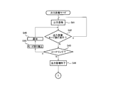
- FIG. 4 is a flowchart for explaining the output restriction mode shown in FIG.
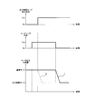
- FIG. 5 is a graph relating to the output restriction mode transition in the control shown in FIG.
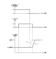
- FIG. 6 is another graph relating to the output restriction mode transition in the control shown in FIG.
- the mode transition control unit 50 sets the operation mode to the normal mode (step S1). In this normal mode, the output of the electric motor 18 is controlled according to the operation command received by the operation command receiving unit 48, and the output of the electric motor 18 is increased or decreased according to the increase or decrease of the accelerator operation amount.
- the transition condition determination unit 47 determines whether or not the output restriction mode transition condition is satisfied (step S2).
- the output restriction mode transition condition is received by the state value receiving unit 46, that is, the state of the drive system electrical equipment including the electric motor 18, the battery 21 and the inverter 22 is in a predetermined non-normal state different from the normal state. There is a condition that the state value becomes a predetermined non-normal value. More specifically, the output restriction mode transition condition is a condition that the temperature of the electric motor 18, the battery 21 or the inverter 22 detected by the temperature sensors 30 to 32 exceeds a predetermined allowable value, and the battery voltage sensor 33.
- the condition that the voltage detected by the battery level is below a predetermined allowable value, the condition that the battery level detected by the battery level sensor 34 is below the predetermined level, and the rotational speed sensor 35 The condition that the rotational speed is equal to or higher than a predetermined upper limit speed, the condition that the vehicle speed detected by the vehicle speed sensor 36 is equal to or higher than the predetermined upper limit speed, and / or an abnormality is detected by the sensor abnormality detection unit 45. It has the condition that
- step S2 If it is determined in step S2 that the output restriction mode transition condition is not satisfied, the process proceeds to step S8. If it is determined in step S2 that the output restriction mode transition condition is satisfied, the mode transition control unit 50 determines whether or not the cornering determination unit 49 determines that the electric motorcycle 1 is cornering (step S2). S3). If it is determined that cornering is not in progress (step S3: N), the motor output target value is gradually brought closer to that in the output limit mode and the mode is automatically shifted to the output limit mode (step S4).
- step S5 the transition to the output restriction mode is prohibited. That is, as shown in FIG. 5, when it is assumed that the target value of the motor output in the normal mode is constant, the output limit mode which is the non-normal mode if the cornering is not performed when the output limit mode transition condition is satisfied. (Two-dot chain line II in FIG. 5).
- the output restriction mode transition condition is satisfied, if cornering is in progress, the target value of the motor output is not decreased from that in the normal mode to that in the output restriction mode, and the normal mode is maintained until cornering is completed.
- step S2 while it is determined that the cornering has been completed while the output restriction mode transition condition is satisfied (step S2: Y), the target value of the motor output is gradually brought closer to that in the output restriction mode. Then, the process automatically shifts to the output restriction mode (step S4). As described above, by gradually bringing the target value of the motor output close to the target value after the mode transition at the time of the mode transition, the mode transition can be completed while maintaining a good driving feeling.
- step S21 when the mode is shifted to the output limit mode, the target value of the motor output is limited to be lower than that in the normal mode.
- step S21 By reducing the output of the electric motor 18 in this way, for example, the electric motor 18, the battery 21 and / or the inverter 22 are protected, the travel speed is reduced when the discharge capacity of the battery 21 is reduced, or the sensor is abnormal, You can multiply the number by a limiter.
- step S22 it is determined whether or not the output restriction mode transition condition is satisfied (step S22). If it is still satisfied, the process returns to step 21. If it is determined in step S21 that the output restriction mode transition condition is not satisfied, the mode transition control unit 50 determines whether or not the cornering determination unit 49 determines that the electric motorcycle 1 is cornering.
- Step S23 If it is determined in step S23 that cornering is in progress, the return (transition) to the normal mode is prohibited (step S24). At the same time, when the mode transition control unit 50 prohibits the return to the normal mode, the notification device 55 notifies the driver to that effect (step 25), and returns to step S22.
- step S23: N when it is determined that the cornering is finished (step S23: N) in a state where the output restriction mode transition condition is not satisfied (step S22: N), the output restriction is released (step S26), and the motor output is reduced. The target value is gradually brought closer to that in the normal mode to shift to the normal mode (step S1).
- the output restriction mode is entered before it is determined that the cornering is being performed
- the output restriction is performed if the cornering is not being performed when the output restriction mode transition condition is not satisfied. It cancels and it transfers to normal mode (two-dot chain line II of FIG. 6).
- the output restriction mode transition condition is not established, if cornering is in progress, the target value of the motor output is not increased from that in the output restriction mode to that in the normal mode, and the output is restricted until cornering is completed. The mode is maintained (solid line I in FIG. 6).
- step S23: N When it is determined that the cornering has been completed (step S23: N) while the output restriction mode transition condition is not satisfied (step S22: Y), the target value of the motor output is gradually changed to that of the normal mode. The output restriction is canceled so as to approach (step S26), and the mode is automatically shifted to the normal mode (step S1).
- FIG. 7 is a flowchart for explaining the regeneration mode shown in FIG.
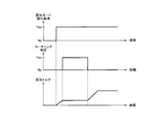
- FIG. 8 is a graph relating to the regeneration mode transition in the control shown in FIG.
- FIG. 9 is another graph relating to the regeneration mode transition in the control shown in FIG.
- the transition condition determination unit 47 determines whether or not the regeneration mode transition condition is satisfied in step S ⁇ b> 7.
- the regeneration mode transition condition is set on the condition that both a possible condition for performing the regeneration operation and a start condition indicating the start of the regeneration operation are satisfied.
- the possible condition is an electrical condition of the electrical device related to the regenerative operation, and is a condition that, for example, a predetermined state where the battery can be charged is satisfied.
- the start condition is, for example, a condition that a wheel rotated by friction with respect to the road surface satisfies a state in which power is supplied to the motor output shaft.
- There are conditions such as a condition that the vehicle is determined to be in a decelerating state and a stop command condition (regeneration start command) for torque generation by the motor from the driver.
- step S7 If it is determined in step S7 that the regeneration mode transition condition is not satisfied, the process proceeds to step S12. If it is determined in step S7 that the regeneration mode transition condition is satisfied, the mode transition control unit 50 determines whether or not the cornering determination unit 49 determines that the electric motorcycle 1 is cornering (step S8). ). If it is determined in step S8 that cornering is in progress, the transition to the regeneration mode is prohibited (step S10). Thereby, even if the regeneration mode transition condition is satisfied, the electric motor 18 is not in the power generation state but is maintained in the driving state. Therefore, by shifting to the regeneration mode during cornering, it is possible to prevent the electric motor 18 from generating negative torque due to power generation and increasing output fluctuation. At the same time, when the mode transition is prohibited, the mode transition control unit 50 notifies the driver of the fact by the notification device 55 (step S11), and returns to step S7.
- step S8: N when it is determined that the cornering has been completed (step S8: N) while the regenerative mode transition condition is satisfied (step S7: Y), the mode is automatically shifted to the regenerative mode (step S9).
- the mode when the mode is changed to the regeneration mode, the electric motor 18 is changed from the driving state to the power generation state, and the kinetic energy transmitted from the rear wheel 3 due to the running inertia is regenerated to the electric energy by the electric motor 18. Charge (step S31).
- step S32 it is determined whether or not the regeneration mode transition condition is satisfied (step S32), and if it is still satisfied, the process returns to step 31. If it is determined in step S32 that the regeneration mode transition condition is not satisfied, the mode transition control unit 50 determines whether or not the cornering determination unit 49 determines that the electric motorcycle 1 is cornering ( Step S33). If it is determined in step S33 that cornering is in progress, the return (transition) to the normal mode is prohibited (step S34). At the same time, when the mode transition control unit 50 prohibits the return to the normal mode, the notification device 55 notifies the driver of the fact (step 35) and returns to step S32.
- step S32: N when it is determined that the cornering has been completed in a state where the regeneration mode transition condition is not satisfied (step S32: N), the regeneration state is canceled and the electric motor 18 is driven from the power generation state. It returns to the state (step S36) and shifts to the normal mode (step S1).
- an increase in regenerative torque during cornering may be limited.
- the regenerative torque during cornering may be substantially constant. In this case, if it is determined that cornering has been completed in a state where the regeneration mode transition condition is satisfied, the target regeneration torque may be gradually approached.
- FIG. 10 is a flowchart for explaining the output rapid increase mode shown in FIG.
- FIG. 11 is a graph relating to the output rapid increase mode transition in the control shown in FIG.
- the transition condition determination unit 47 determines whether or not the output rapid increase mode transition condition is satisfied in step S14.
- the output rapid increase mode transition condition is set on condition that both a condition capable of executing the output rapid increase operation and a start condition indicating the start of the output rapid increase operation are satisfied.
- the possible condition is an electrical condition of the electric device related to the output rapid increase operation, and is a condition that, for example, a predetermined state where the battery can be charged is satisfied.
- the start condition is a condition that a signal for a sudden increase output is directly or indirectly acquired from the driver.
- there is a condition that the accelerator grip 7 is suddenly accelerated that is, it is determined that the increase rate of the accelerator operation amount detected by the accelerator operation amount sensor 37 is not less than a predetermined value.
- a special operation such as an accelerator operation in a disconnected state by a rapid acceleration switch or a clutch may be used as a condition.
- step S12 determines whether or not the output rapid increase mode transition condition is not satisfied. If it is determined in step S12 that the output rapid increase mode transition condition is satisfied, the mode transition control unit 50 determines whether or not the cornering determination unit 49 determines that the electric motorcycle 1 is cornering (step S12). S13). When it is determined in step S13 that cornering is being performed, the mode transition control unit 50 determines whether or not the electric motorcycle 1 has been determined to be in the final stage of cornering by the cornering determination unit 49 (step S14). ). Specifically, the cornering determination unit 49 also serves as a corner escape determination unit that determines whether or not the end of cornering, that is, whether or not the electric motorcycle 1 is about to exit the corner. When the increase rate of the bank angle detected by the sensor 41 is reversed from positive to negative and / or when the accelerator operation amount is increased during cornering, it is determined that the cornering is at the final stage.
- step S15 If it is not determined in step S16 that the electric motorcycle 1 is in the final stage of cornering, the shift to the output rapid increase mode is prohibited (step S15). Therefore, the normal state is maintained as shown in FIG. As a result, it is prevented that the output rapid increase mode is established during cornering and the rapid output increase condition is satisfied, and the motor output is corrected to increase and output fluctuations are not increased.
- the mode transition control unit 50 notifies the driver of this by the notification device 55 (step S16), and returns to step S12.
- step S12: Y when it is determined that cornering is not being performed (step S13: N), the mode transition control unit 50 shifts to the output rapid increase mode (step S17).
- step S12 when the output rapid increase mode transition condition is satisfied (step S12: Y), when it is determined that the cornering is in the final stage (step S14: Y), the mode transition control unit 50 transitions to the output rapid increase mode. (Step S17). According to this, at the end of cornering, the motor output increase correction is not prohibited and large acceleration is allowed, so that smooth acceleration traveling at the cornering exit can be realized.
- step S41 the motor output is increased and corrected as compared with the correspondence relationship between the accelerator operation amount and the motor output in the normal mode.
- the motor output temporarily increases as compared to the normal mode, instantaneously greater acceleration than usual occurs, and the acceleration response felt by the driver is improved.
- step S42 it is determined whether or not the output rapid increase mode transition condition is satisfied (step S42), and if it is still satisfied, the process returns to step 41.
- step S42 when it is determined that the output rapid increase mode transition condition is not satisfied, the mode transition control unit 50 determines whether or not the cornering determination unit 49 determines that the electric motorcycle 1 is cornering. (Step S43). If it is determined in step S43 that cornering is in progress, the return (transition) to the normal mode is prohibited (step S44). At the same time, when the mode transition control unit 50 prohibits the return to the normal mode, the notification device 55 notifies the driver of that fact (step 45) and returns to step S42.
- step S43: N when it is determined that cornering is not being performed (step S43: N) in a state where the output rapid increase mode transition condition is not satisfied (step S42: N), the mode transition control unit 50 ends the output rapid increase (step S43: N). S46), the mode is shifted to the normal mode (step S1).
- the output restriction caused by the occurrence of an abnormality in the electric device is executed, thereby reducing the influence of the change in the driving feeling that occurs when the output is restricted, thereby protecting the electric device and driving the output in an abnormal state.
- the output limit state is maintained until cornering is completed, and the driving feeling during cornering is prevented by preventing the output from increasing during cornering. Can be maintained.
- the vehicle output can be changed according to the driver's intention even during cornering, resulting in a decrease in operability. Is prevented. Further, the output change caused by the start / end of the regenerative operation and the start / end of the permission for rapid increase of output is also prohibited during cornering, whereby the same effect of maintaining the driving feeling can be obtained. Exceptionally, at the end of cornering, the execution operation desired by the driver can be obtained by permitting the execution of the output rapid increase permission mode based on the driver's request.
- FIG. 12 is a graph corresponding to FIG. 8 of the first modified example regarding the output restriction mode transition.
- FIG. 13 is a graph corresponding to FIG. 8 of the second modification example regarding the output restriction mode transition.
- mode transition is prohibited in step S5 (FIG. 3) as shown in FIGS. 3 and 5, but instead, the mode transition condition is satisfied as shown by the solid line A in FIG.
- the output change is suppressed so as to reduce the rate of time change of the output of the electric motor 18 compared to when it is determined that the mode transition condition is satisfied and cornering is not being performed. May be.
- the rate of change of the output of the electric motor 18 at the time of mode transition is reduced, the output fluctuation of the electric motor 18 accompanying the mode transition can be suppressed while the mode transition is being performed.
- the amount of change in the output of the electric motor 18 may be reduced as shown by the solid line A in FIG. In this way, since the amount of change in the output of the electric motor 18 at the time of mode transition is reduced, the output fluctuation of the electric motor 18 accompanying the mode transition can be suppressed while the mode transition is being performed.
- the effect of the present invention that is, the effect of preventing a decrease in running feeling can be obtained by suppressing the output change instead of prohibiting the output change.
- the effect of the output change can be obtained even during cornering by executing the output change while relaxing the output change even during cornering.
- the change width or time change may be small compared to the case of non-cornering, a protective effect, a regenerative effect, and the like of the electric device can be obtained.
- the mode transition control unit 50 responds to the vehicle operating state (at least one of bank angle, motor rotation speed, vehicle speed, gear ratio, corner curvature) during cornering.
- the degree of suppression of the output change of the electric motor 18 may be changed. For example, when the vehicle is in a driving state in which the influence of fluctuations in travel power on the driver is small, the degree of suppression of the output change of the electric motor 18 is reduced (solid line A in FIGS. 12 and 13), When the vehicle operation state has a large influence on the vehicle, the degree of suppression of the output change of the electric motor 18 is increased as compared with the vehicle operation state where the influence on the driver due to fluctuations in travel power is small (FIGS. 12 and 13). Dash-dot line B).
- the electric motor 18 is compared with the case where it is determined that the mode transition condition is satisfied and the cornering is not being performed.
- the time change rate of output may be reduced. Further, for example, when the vehicle driving state has a small influence on the driver due to fluctuations in travel power, the output change of the electric motor 18 is not suppressed, and when the vehicle driving state has a large influence on the driver due to fluctuations in travel power, You may make it suppress the output change of the electric motor 18.
- the cornering determination unit 49 determines whether cornering is being performed based on information from the bank angle sensor 41, but may be performed by other methods. For example, it may be determined that cornering is being performed when the steering angle detected by the steering angle sensor is greater than a predetermined value, or when the lateral acceleration detected by the lateral acceleration sensor is greater than a predetermined value. It may be determined that cornering is being performed, or it may be determined that cornering is being performed when the lateral vehicle body inclination angle detected by the gyro sensor increases.
- cornering determination may be made based on the difference between the front wheel speed and the rear wheel speed. Specifically, when the front and rear wheels have different wheel widths and cross-sectional radii, the speed difference between the front and rear wheels changes corresponding to the cornering of the vehicle body. Therefore, the presence or absence of cornering of the vehicle body can be determined based on the value related to the speed difference between the front and rear wheels. For example, the cornering state may be determined when the rotational speed of the front wheels is greater than a predetermined value compared to the rear wheels.
- the cornering state is a case where the vehicle inclination angle from the upright state is equal to or greater than a predetermined angle. May be.
- the state in which the slalom traveling state ends may be the end of cornering.
- the cornering may be determined to end when a predetermined time, for example, 1 second elapses after the inclination angle becomes less than a predetermined value. Accordingly, it is possible to prevent the possibility of erroneous determination as the end of cornering when the vehicle is only temporarily upright during slalom traveling.
- the vehicle may be determined that the vehicle is in the slalom traveling when the time change of the tilt angle when the tilt angle approaches less than a predetermined value is short.
- the slalom running determination may be performed by other methods.
- the present invention includes a case where slalom traveling is not included.
- the change during cornering is suppressed on both the output decreasing side and the output increasing side.
- the present invention is not limited to this, and only one of the output decreasing side and the output increasing side is suppressed.
- the output change related to the three output change modes of the output restriction mode, the regeneration mode, and the output sudden increase mode during cornering is restricted. However, it is not necessary to have all of them, and at least one of them is restricted. Such cases are also included in the present invention.
- the operation is performed in the order of the output restriction mode, the regeneration mode, and the output rapid increase mode from the start of the control. However, the case where the order of these three modes is different is also included in the present invention.
- the operation mode transition example described in the present embodiment is an example, and the present invention can be applied as long as the operation mode is changed based on information different from the command given by the driver.
- Examples of transition to operation modes other than the embodiment are also included.
- regenerative power adjustment according to the running state, and operation mode transition due to torque / rotation speed / running speed limitation are also included.
- mode transition is prohibited when the output restriction mode transition condition is satisfied in a state where it is determined that cornering is being performed, but the output restriction mode transition condition is satisfied and transition is made to the output restriction mode. Even when it is determined that cornering is in progress in the transitional state (cornering has started), the mode transition is temporarily stopped at that point to suppress the output change that accompanies the mode transition and the cornering is completed. Then, the migration may be completed.
- the vehicle driving source is not limited to the electric motor 18 and may be a driving source such as an engine. Further, the vehicle is not limited to a two-wheeled vehicle, but can be applied to a vehicle such as a four-wheeled vehicle or a small planing boat.
- the vehicle is preferably used for a vehicle that tilts the vehicle body during cornering.
- the output is suppressed during cornering.
- the presence / absence of output suppression during cornering is switched between the first state in which the driving feeling is emphasized and the second state in which the protection of electrical equipment is emphasized. Also good. In other words, output suppression during cornering may not be performed in the first state, and output suppression during cornering may be performed in the second state.
- the motor output is gradually brought closer to the target value of the mode after the transition, but may be brought closer to one at a stroke.
- a switch for instructing cancellation of output suppression may be provided, and output suppression may be canceled by a signal given from the switch by the driver's operation. This can improve convenience.
- the setting of the suppression change, the threshold value for entering the suppression mode, and the like may be configured to be variable.
- the present invention is not limited to the above-described embodiment, and the configuration can be changed, added, or deleted without departing from the spirit of the present invention.
- the electric motorcycle, the vehicle control device, and the vehicle control method according to the present invention can improve driving feeling during cornering in a vehicle in which the driving mode shifts according to a state value other than the driving command. It is beneficial to apply widely to vehicles such as electric motorcycles that have the excellent effect of
Landscapes
- Engineering & Computer Science (AREA)
- Mechanical Engineering (AREA)
- Transportation (AREA)
- Power Engineering (AREA)
- Life Sciences & Earth Sciences (AREA)
- Sustainable Development (AREA)
- Sustainable Energy (AREA)
- Chemical & Material Sciences (AREA)
- Combustion & Propulsion (AREA)
- Electric Propulsion And Braking For Vehicles (AREA)
- Arrangement Or Mounting Of Propulsion Units For Vehicles (AREA)
Abstract
Description
18 電動モータ
21 バッテリ
22 インバータ
23 ECU(制御手段、乗物制御装置)
30 温度センサ(状態値検出手段)
31 インバータ温度センサ(状態値検出手段)
32 バッテリ温度センサ(状態値検出手段)
33 バッテリ電圧センサ(状態値検出手段)
34 バッテリ残量センサ(状態値検出手段)
35 回転数センサ(状態値検出手段)
36 車速センサ(状態値検出手段)
37 アクセル操作量センサ(運転指令検出手段)
38 ブレーキセンサ(運転指令検出手段)
39 クラッチスイッチ(運転指令検出手段)
40 ギヤ位置センサ(運転指令検出手段)
41 バンク角センサ
45 センサ異常検知部(状態値検出手段)
48 運転指令受信部
46 状態値受信部
49 コーナリング判定部
50 モード移行制御部
51 通常モード実行部
52 出力制限モード実行部(非通常モード実行部)
53 回生モード実行部(非通常モード実行部)
54 出力急増モード実行部(非通常モード実行部)
55 通知装置
Claims (12)
- 運転者からの運転指令を検出する運転指令検出手段と、
前記運転指令とは異なる状態値を検出可能な状態値検出手段と、
駆動輪に伝達される走行動力を発生する電動モータと、
前記運転指令検出手段で検出された前記運転指令に応じて前記電動モータの出力を制御する通常モードと、前記電動モータの出力を前記通常モードに対して異ならせる非通常モードとを実行可能であり、前記通常モード及び前記非通常モードのうち一方のモードにおいて前記状態値検出手段で検出される前記状態値に所定の移行条件が成立すると、前記通常モード及び前記非通常モードのうち他方のモードへと移行させる制御手段と、
電動二輪車がコーナリング中であるか否かを判定するコーナリング判定手段と、を備え、
前記制御手段は、前記コーナリング判定手段で電動二輪車がコーナリング中であると判定され且つ前記移行条件が成立したときには、前記コーナリング判定手段で電動二輪車がコーナリング中ではないと判定され且つ前記移行条件が成立したときよりも、前記電動モータの出力変化を抑制する、電動二輪車。 - 前記制御手段は、前記コーナリング判定手段で電動二輪車がコーナリング中であると判定され且つ前記移行条件が成立したときには、前記通常モード及び前記非通常モードのうち一方のモードから他方のモードへの移行を禁止する、請求項1に記載の電動二輪車。
- 前記制御手段は、前記コーナリング判定手段で電動二輪車がコーナリング中であると判定され且つ前記移行条件が成立したときには、前記コーナリング判定手段で電動二輪車がコーナリング中ではないと判定され且つ前記移行条件が成立したときよりも、前記通常モード及び前記非通常モードのうち一方のモードから他方のモードへ移行する際における前記電動モータの出力の変化量及び時間変化率の少なくとも一方を低減する、請求項1に記載の電動二輪車。
- 前記電動モータに電力を供給するためのバッテリと、前記電動モータと前記バッテリとの間に介設されたインバータとを備え、
前記状態値検出手段は、前記電動モータ、前記バッテリ及び前記インバータを含む駆動系電気機器のうち少なくとも1つの状態を前記状態値として検出し、
前記移行条件は、前記通常モードから前記非通常モードに移行させるための条件であって前記状態値が所定の非通常値であるとの非通常モード移行条件と、前記非通常モードから前記通常モードに移行させるための条件であって前記状態値が所定の通常値であるとの通常モード移行条件とを有し、
前記制御手段は、前記非通常モードにおける前記電動モータの出力を、前記通常モードにおける前記電動モータの出力よりも減少させる、請求項1乃至3のいずれかに記載の電動二輪車。 - 前記電動モータに電力を供給するためのバッテリと、前記バッテリと前記電動モータとの間に介設されたインバータと、を備え、
前記状態値検出手段は、前記バッテリ、前記インバータ及び前記電動モータのうち少なくとも1つの温度を前記状態値として検出する温度センサ、前記バッテリの放電能力を前記状態値として検出するバッテリセンサ、前記電動モータの回転数を前記状態値として検出する回転数センサ、走行速度を前記状態値として検出する車速センサ、及び、前記電動モータの制御のための入力情報を検出するセンサの異常を前記状態値として検知する異常検知手段のうち少なくとも1つを含み、
前記移行条件は、前記温度センサで検出される温度が所定の許容値を超えているとの条件、前記バッテリセンサで検出される放電能力が所定の許容値を下回っているとの条件、前記回転数センサで検出される回転数が所定の上限回転数以上であるとの条件、前記車速センサで検出される車速が所定の上限速度以上であるとの条件、及び、前記異常検知手段で異常が検知されたとの条件のうち少なくとも1つである出力制限モード移行条件を有し、
前記非通常モードは、前記通常モードよりも前記電動モータの出力を減少させる出力制限モードを有し、
前記制御手段は、前記通常モードにおいて前記出力制限モード移行条件が成立すると、前記出力制限モードに移行させる、請求項1乃至3のいずれかに記載の電動二輪車。 - 前記制御手段は、前記コーナリング判定手段で電動二輪車がコーナリング中であると判定され且つ前記移行条件が成立することで前記電動モータの出力変化を抑制された状態から、前記移行条件が成立したまま前記コーナリング判定手段によりコーナリングが終了したことが判定されると、前記電動モータの出力の目標値をモード移行後の目標値に徐々に近づけるように制御する、請求項1乃至5のいずれかに記載の電動二輪車。
- 前記移行条件は、所定の出力急増モード移行条件を有し、
前記非通常モードは、前記運転指令検出手段で検出されたアクセル操作量の増加率が所定の閾値以上であるときに、前記通常モードよりも前記電動モータの出力を一時的に増加させる出力急増モードを有し、
前記制御手段は、前記通常モードにおいて前記出力急増モード移行条件が成立すると、前記出力急増モードに移行させる、請求項1乃至6のいずれかに記載の電動二輪車。 - 走行状態がコーナリングの終盤であるか否かを判定するコーナリング状態判定手段を備え、
前記制御手段は、前記コーナリング状態判定手段により走行状態がコーナリングの終盤であると判定された場合には、前記コーナリング判定手段で電動二輪車がコーナリング中であると判定され且つ前記出力急増モード移行条件が成立しても、前記電動モータの出力変化の抑制を実施しない、請求項7に記載の電動二輪車。 - 運転者に通知するための通知手段を備え、
前記制御手段は、前記コーナリング判定手段で電動二輪車がコーナリング中であると判定されかつ前記移行条件が成立したときには、前記電動モータの出力変化を抑制している旨を前記通知手段により運転者に通知させる、請求項1乃至8のいずれかに記載の電動二輪車。 - 前記制御手段は、コーナリング中の車両運転状態に応じて前記電動モータの出力変化の抑制の程度を変化させる、請求項1乃至9のいずれかに記載の電動二輪車。
- 運転者からの運転指令を受信する運転指令受信部と、
前記運転指令とは異なる状態値を受信可能な状態値受信部と、
前記運転指令に応じて走行駆動源の出力を制御する通常モード実行部と、
前記走行駆動源の出力を前記通常モードに対して異ならせる非通常モード実行部と、
前記通常モード及び前記非通常モードのうち一方のモードにおいて前記状態値受信部で受信される前記状態値に所定の移行条件が成立すると、前記通常モード及び前記非通常モードのうち他方のモードへと移行させるモード移行制御部と、
乗物がコーナリング中であるか否かを判定するコーナリング判定部と、を備え、
前記モード移行制御部は、前記コーナリング判定部で乗物がコーナリング中であると判定され且つ前記移行条件が成立したときには、前記コーナリング判定部で乗物がコーナリング中ではないと判定され且つ前記移行条件が成立したときよりも、前記走行駆動源の出力変化を抑制する、乗物制御装置。 - 運転者からの運転指令を受信する運転指令受信工程と、
前記運転指令とは異なる状態値を受信可能な状態値受信工程と、
前記運転指令に応じて走行駆動源の出力を制御する通常モード実行工程と、
前記走行駆動源の出力を前記通常モードに対して異ならせる非通常モード実行工程と、
前記通常モード及び前記非通常モードのうち一方のモードにおいて前記状態値に所定の移行条件が成立すると、前記通常モード及び前記非通常モードのうち他方のモードへと移行させるモード移行制御工程と、
乗物がコーナリング中であるか否かを判定するコーナリング判定工程と、を備え、
前記モード移行制御工程では、前記コーナリング判定部で乗物がコーナリング中であると判定され且つ前記移行条件が成立したときには、前記コーナリング判定部で乗物がコーナリング中ではないと判定され且つ前記移行条件が成立したときよりも、前記走行駆動源の出力変化を抑制する、乗物制御方法。
Priority Applications (6)
| Application Number | Priority Date | Filing Date | Title |
|---|---|---|---|
| EP11865937.4A EP2708457B1 (en) | 2011-05-13 | 2011-05-13 | Electric motorcycle, vehicle controller and vehicle control method |
| JP2013514845A JP5767701B2 (ja) | 2011-05-13 | 2011-05-13 | 電動二輪車、乗物制御装置及び乗物制御方法 |
| PCT/JP2011/002666 WO2012157013A1 (ja) | 2011-05-13 | 2011-05-13 | 電動二輪車、乗物制御装置及び乗物制御方法 |
| US14/117,364 US20140058609A1 (en) | 2011-05-13 | 2011-05-13 | Electric Motorcycle, Vehicle Controller and Vehicle Control Method |
| CN201180070505.XA CN103502088B (zh) | 2011-05-13 | 2011-05-13 | 电动摩托车、交通工具控制装置及交通工具控制方法 |
| US15/642,213 US10351121B2 (en) | 2011-05-13 | 2017-07-05 | Electric motorcycle, vehicle controller and vehicle control method |
Applications Claiming Priority (1)
| Application Number | Priority Date | Filing Date | Title |
|---|---|---|---|
| PCT/JP2011/002666 WO2012157013A1 (ja) | 2011-05-13 | 2011-05-13 | 電動二輪車、乗物制御装置及び乗物制御方法 |
Related Child Applications (2)
| Application Number | Title | Priority Date | Filing Date |
|---|---|---|---|
| US14/117,364 A-371-Of-International US20140058609A1 (en) | 2011-05-13 | 2011-05-13 | Electric Motorcycle, Vehicle Controller and Vehicle Control Method |
| US15/642,213 Division US10351121B2 (en) | 2011-05-13 | 2017-07-05 | Electric motorcycle, vehicle controller and vehicle control method |
Publications (1)
| Publication Number | Publication Date |
|---|---|
| WO2012157013A1 true WO2012157013A1 (ja) | 2012-11-22 |
Family
ID=47176385
Family Applications (1)
| Application Number | Title | Priority Date | Filing Date |
|---|---|---|---|
| PCT/JP2011/002666 Ceased WO2012157013A1 (ja) | 2011-05-13 | 2011-05-13 | 電動二輪車、乗物制御装置及び乗物制御方法 |
Country Status (5)
| Country | Link |
|---|---|
| US (2) | US20140058609A1 (ja) |
| EP (1) | EP2708457B1 (ja) |
| JP (1) | JP5767701B2 (ja) |
| CN (1) | CN103502088B (ja) |
| WO (1) | WO2012157013A1 (ja) |
Cited By (8)
| Publication number | Priority date | Publication date | Assignee | Title |
|---|---|---|---|---|
| JP2015071404A (ja) * | 2013-09-09 | 2015-04-16 | ブリヂストンサイクル株式会社 | 電動機付自転車 |
| JP2015144549A (ja) * | 2013-12-26 | 2015-08-06 | 株式会社デンソー | 車両診断システム及び車両診断方法 |
| JP2016176345A (ja) * | 2015-03-18 | 2016-10-06 | 株式会社ケーヒン | 駆動力制御装置 |
| JP2016185746A (ja) * | 2015-03-27 | 2016-10-27 | スズキ株式会社 | 電動二輪車の走行制御装置およびその走行制御方法 |
| WO2020240987A1 (ja) * | 2019-05-30 | 2020-12-03 | ヤマハ発動機株式会社 | 傾斜車両 |
| JP2023075459A (ja) * | 2021-11-19 | 2023-05-31 | カワサキモータース株式会社 | 鞍乗車両、車両の制御方法及び制御プログラム |
| WO2025095070A1 (ja) * | 2023-10-31 | 2025-05-08 | ヤマハ発動機株式会社 | リーン車両 |
| EP4685002A1 (en) | 2024-07-25 | 2026-01-28 | Yamaha Hatsudoki Kabushiki Kaisha | Straddled electric vehicle |
Families Citing this family (24)
| Publication number | Priority date | Publication date | Assignee | Title |
|---|---|---|---|---|
| CN103502088B (zh) | 2011-05-13 | 2018-01-16 | 川崎重工业株式会社 | 电动摩托车、交通工具控制装置及交通工具控制方法 |
| US9238497B2 (en) * | 2011-12-28 | 2016-01-19 | Kawasaki Jukogyo Kabushiki Kaisha | Electric motorcycle |
| CN104718100B (zh) * | 2012-10-22 | 2017-03-08 | 川崎重工业株式会社 | 电动车辆的再生制动控制系统 |
| US9868490B2 (en) * | 2012-12-25 | 2018-01-16 | Kawasaki Jukogyo Kabushiki Kaisha | Electric vehicle |
| DE102014214594A1 (de) | 2014-07-24 | 2016-01-28 | Robert Bosch Gmbh | Verfahren zum Betreiben eines Assistenzsystems eines Fahrzeugs mit mindestens einem elektrischen Energiespeicher |
| KR102170700B1 (ko) * | 2014-12-30 | 2020-10-27 | 한화디펜스 주식회사 | 차량 제어 장치 및 차량 제어 방법 |
| JP6341123B2 (ja) * | 2015-03-16 | 2018-06-13 | スズキ株式会社 | 燃料電池加湿装置および燃料電池二輪車 |
| JP6582125B2 (ja) * | 2016-03-31 | 2019-09-25 | 本田技研工業株式会社 | 自動二輪車のブレーキ制御装置 |
| US10622870B2 (en) * | 2016-05-02 | 2020-04-14 | Faraday & Future Inc. | Operating point determination in an electric motor system |
| US10700629B2 (en) | 2016-05-02 | 2020-06-30 | Faraday&Future Inc. | Operating point determination in an electric motor system |
| JP6735158B2 (ja) * | 2016-06-14 | 2020-08-05 | 株式会社シマノ | 自転車用制御装置 |
| JP6685183B2 (ja) * | 2016-06-14 | 2020-04-22 | ブリヂストンサイクル株式会社 | 電動機付自転車および報知装置 |
| KR102417517B1 (ko) * | 2016-11-24 | 2022-07-05 | 현대자동차주식회사 | 친환경 차량의 모터시스템 제어 방법 |
| CN106627568A (zh) * | 2016-12-15 | 2017-05-10 | 重庆典果成实业有限公司 | 摩托车转弯安全辅助系统 |
| JP7205968B2 (ja) | 2018-12-18 | 2023-01-17 | カワサキモータース株式会社 | ハイブリッド式リーン車両の制御装置 |
| JP7185517B2 (ja) * | 2018-12-18 | 2022-12-07 | カワサキモータース株式会社 | ハイブリッド式リーン車両の制御装置 |
| CN109572488A (zh) * | 2019-01-09 | 2019-04-05 | 合肥工业大学 | 一种燃料电池混合动力系统及其控制方法 |
| CN112241511B (zh) * | 2019-07-19 | 2024-05-14 | 上海杰之能软件科技有限公司 | 交通工具辅助电气系统的性能检测方法及装置、终端 |
| JP7343428B2 (ja) * | 2020-03-16 | 2023-09-12 | トヨタ自動車株式会社 | ハイブリッド車両の駆動装置 |
| CN111439135A (zh) * | 2020-04-28 | 2020-07-24 | 雅迪科技集团有限公司 | 一种电动车转把控制方法及系统 |
| ES2875223A1 (es) * | 2020-05-04 | 2021-11-08 | Cecotec Res And Development | Sistema de control de traccion para vehiculo electrico de dos ruedas |
| CN111572351A (zh) * | 2020-05-08 | 2020-08-25 | 重庆北斗捷安新能源科技有限公司 | 一种电动两轮车的辅助驻车系统及其辅助方法 |
| CN112706869B (zh) * | 2020-12-30 | 2022-03-18 | 台铃科技发展有限公司 | 一种具有能量回收功能的电动自行车 |
| US12485981B2 (en) | 2021-03-24 | 2025-12-02 | Polaris Industries Inc. | Electric recreational vehicle |
Citations (4)
| Publication number | Priority date | Publication date | Assignee | Title |
|---|---|---|---|---|
| JPH0638305A (ja) * | 1992-07-17 | 1994-02-10 | Aqueous Res:Kk | ハイブリッド型車両 |
| JPH09191582A (ja) | 1996-01-11 | 1997-07-22 | Nissan Motor Co Ltd | 電気自動車制御装置 |
| JPH09284911A (ja) * | 1996-04-08 | 1997-10-31 | Toyota Motor Corp | 4輪駆動型ハイブリッド車両の駆動制御装置 |
| JP2007131179A (ja) * | 2005-11-10 | 2007-05-31 | Yamaha Motor Co Ltd | ハイブリッド車両の駆動制御装置及びこれを備えるハイブリッド車両 |
Family Cites Families (20)
| Publication number | Priority date | Publication date | Assignee | Title |
|---|---|---|---|---|
| US5453930A (en) * | 1991-02-08 | 1995-09-26 | Nissan Motor Co., Ltd. | Drive system for electric automobiles |
| US6104154A (en) * | 1997-02-26 | 2000-08-15 | Daiwa Sangyo Co., Ltd. | Tricycle with electric motor |
| JP3641160B2 (ja) * | 1999-04-07 | 2005-04-20 | 光洋精工株式会社 | パワーステアリング装置 |
| US6268794B1 (en) * | 2000-01-21 | 2001-07-31 | Harley-Davidson Motor Company Group, Inc. | Integrated security, tip-over, and turn signal system |
| DE10242124B4 (de) * | 2002-09-11 | 2009-12-10 | Robert Bosch Gmbh | Verfahren und Vorrichtung zur Einstellung des Motormoments eines einspurigen Kraftfahrzeugs |
| CN2734550Y (zh) * | 2004-09-29 | 2005-10-19 | 西安交通大学 | 一种电动自行车或电动摩托车限速控制器 |
| JP4480018B2 (ja) * | 2005-03-16 | 2010-06-16 | 本田技研工業株式会社 | 電動車両の表示装置 |
| CN101209679A (zh) * | 2006-12-31 | 2008-07-02 | 西南大学 | 电动车自动换档控制器 |
| JP4432984B2 (ja) * | 2007-03-06 | 2010-03-17 | トヨタ自動車株式会社 | 自動変速機の制御装置 |
| US20100065361A1 (en) * | 2008-09-17 | 2010-03-18 | T3 Motion, Inc. | Battery Powered Vehicle Control Systems and Methods |
| WO2010135472A2 (en) * | 2009-05-19 | 2010-11-25 | Ev-Ip, Llc | Methods and apparatus for utilizing electrically powered vehicles |
| DE102009054756A1 (de) * | 2009-12-16 | 2011-06-22 | Robert Bosch GmbH, 70469 | Elektrisches Zweirad |
| US8744732B2 (en) * | 2009-12-28 | 2014-06-03 | Kawasaki Jukogyo Kabushiki Kaisha | Vehicle and engine controlling method |
| JP5615095B2 (ja) * | 2010-08-25 | 2014-10-29 | 本田技研工業株式会社 | 電動車両のメータ表示装置 |
| WO2012026044A1 (ja) * | 2010-08-27 | 2012-03-01 | トヨタ自動車株式会社 | 車両用制御装置 |
| CN103502088B (zh) | 2011-05-13 | 2018-01-16 | 川崎重工业株式会社 | 电动摩托车、交通工具控制装置及交通工具控制方法 |
| US8725312B2 (en) * | 2011-08-12 | 2014-05-13 | Kawasaki Jukogyo Kabushiki Kaisha | System for obtaining information in vehicle |
| US20140062228A1 (en) * | 2012-09-04 | 2014-03-06 | Neil Carpenter | Thermal management of electric motor in the event of failure of primary cooling system for powertrain on electric vehicle |
| JP2015533275A (ja) * | 2012-10-04 | 2015-11-19 | マグナ イー−カー システムズ オブ アメリカ インコーポレイテッド | 電気自動車における冷却液によって冷却された熱負荷の温度に基づくコンプレッサの出口圧制御 |
| GB2525138B (en) * | 2013-09-11 | 2016-06-08 | Jaguar Land Rover Ltd | Vehicle controller and method |
-
2011
- 2011-05-13 CN CN201180070505.XA patent/CN103502088B/zh active Active
- 2011-05-13 EP EP11865937.4A patent/EP2708457B1/en active Active
- 2011-05-13 US US14/117,364 patent/US20140058609A1/en not_active Abandoned
- 2011-05-13 JP JP2013514845A patent/JP5767701B2/ja active Active
- 2011-05-13 WO PCT/JP2011/002666 patent/WO2012157013A1/ja not_active Ceased
-
2017
- 2017-07-05 US US15/642,213 patent/US10351121B2/en active Active
Patent Citations (4)
| Publication number | Priority date | Publication date | Assignee | Title |
|---|---|---|---|---|
| JPH0638305A (ja) * | 1992-07-17 | 1994-02-10 | Aqueous Res:Kk | ハイブリッド型車両 |
| JPH09191582A (ja) | 1996-01-11 | 1997-07-22 | Nissan Motor Co Ltd | 電気自動車制御装置 |
| JPH09284911A (ja) * | 1996-04-08 | 1997-10-31 | Toyota Motor Corp | 4輪駆動型ハイブリッド車両の駆動制御装置 |
| JP2007131179A (ja) * | 2005-11-10 | 2007-05-31 | Yamaha Motor Co Ltd | ハイブリッド車両の駆動制御装置及びこれを備えるハイブリッド車両 |
Non-Patent Citations (1)
| Title |
|---|
| See also references of EP2708457A4 * |
Cited By (10)
| Publication number | Priority date | Publication date | Assignee | Title |
|---|---|---|---|---|
| JP2015071404A (ja) * | 2013-09-09 | 2015-04-16 | ブリヂストンサイクル株式会社 | 電動機付自転車 |
| JP2015144549A (ja) * | 2013-12-26 | 2015-08-06 | 株式会社デンソー | 車両診断システム及び車両診断方法 |
| JP2016176345A (ja) * | 2015-03-18 | 2016-10-06 | 株式会社ケーヒン | 駆動力制御装置 |
| JP2016185746A (ja) * | 2015-03-27 | 2016-10-27 | スズキ株式会社 | 電動二輪車の走行制御装置およびその走行制御方法 |
| WO2020240987A1 (ja) * | 2019-05-30 | 2020-12-03 | ヤマハ発動機株式会社 | 傾斜車両 |
| JPWO2020240987A1 (ja) * | 2019-05-30 | 2020-12-03 | ||
| JP2023075459A (ja) * | 2021-11-19 | 2023-05-31 | カワサキモータース株式会社 | 鞍乗車両、車両の制御方法及び制御プログラム |
| JP7769523B2 (ja) | 2021-11-19 | 2025-11-13 | カワサキモータース株式会社 | 鞍乗車両、車両の制御方法及び制御プログラム |
| WO2025095070A1 (ja) * | 2023-10-31 | 2025-05-08 | ヤマハ発動機株式会社 | リーン車両 |
| EP4685002A1 (en) | 2024-07-25 | 2026-01-28 | Yamaha Hatsudoki Kabushiki Kaisha | Straddled electric vehicle |
Also Published As
| Publication number | Publication date |
|---|---|
| EP2708457A4 (en) | 2015-04-29 |
| CN103502088B (zh) | 2018-01-16 |
| JP5767701B2 (ja) | 2015-08-19 |
| US20170297552A1 (en) | 2017-10-19 |
| CN103502088A (zh) | 2014-01-08 |
| EP2708457B1 (en) | 2017-01-18 |
| EP2708457A1 (en) | 2014-03-19 |
| JPWO2012157013A1 (ja) | 2014-07-31 |
| US10351121B2 (en) | 2019-07-16 |
| US20140058609A1 (en) | 2014-02-27 |
Similar Documents
| Publication | Publication Date | Title |
|---|---|---|
| JP5767701B2 (ja) | 電動二輪車、乗物制御装置及び乗物制御方法 | |
| JP5865509B2 (ja) | 電動式乗物の回生ブレーキ制御システム | |
| EP2910401B1 (en) | Regenerative brake control system of electric vehicle | |
| EP3115579B1 (en) | Drive torque control method, drive torque control device and vehicle | |
| CN105531168B (zh) | 车辆的控制装置 | |
| JP6112303B2 (ja) | 車両用挙動制御装置 | |
| JP2018023223A (ja) | 電動車両 | |
| WO2012090253A1 (ja) | 電動車両の回生制御システム | |
| JP7561054B2 (ja) | 車両用制御装置 | |
| WO2014162830A1 (ja) | 左右モータ駆動車輪の駆動力制御装置 | |
| JP4513612B2 (ja) | 車両のトルク配分制御装置 | |
| JP2021027648A (ja) | 変速制御方法及び変速制御システム | |
| JP5386273B2 (ja) | 鞍乗型乗物用エンジン制御装置 | |
| JP7205968B2 (ja) | ハイブリッド式リーン車両の制御装置 | |
| WO2016136731A1 (ja) | 駆動トルク制御装置、駆動源ユニットおよび車両 | |
| JP7169201B2 (ja) | リーン車両の制御装置及び転倒予測方法 | |
| JP2013193596A (ja) | 車両制御装置 | |
| JP2016053323A (ja) | トラクション制御システムおよび鞍乗り型車両 | |
| JP2014080084A (ja) | ハイブリッド自動車のローリング抑制方法 | |
| JP4779680B2 (ja) | 操舵輪の振動に基づきパワーステアリング装置が制御される車輌 | |
| JP2006298094A (ja) | 車両停止保持装置 | |
| JP2020080591A (ja) | 電動車両 | |
| JP2016086554A (ja) | 左右輪駆動力差制御装置 | |
| JP2024006579A (ja) | 車両の制御装置 | |
| WO2015151265A1 (ja) | 電動システムおよびそれを備える輸送機器 |
Legal Events
| Date | Code | Title | Description |
|---|---|---|---|
| 121 | Ep: the epo has been informed by wipo that ep was designated in this application |
Ref document number: 11865937 Country of ref document: EP Kind code of ref document: A1 |
|
| ENP | Entry into the national phase |
Ref document number: 2013514845 Country of ref document: JP Kind code of ref document: A |
|
| REEP | Request for entry into the european phase |
Ref document number: 2011865937 Country of ref document: EP |
|
| WWE | Wipo information: entry into national phase |
Ref document number: 2011865937 Country of ref document: EP |
|
| WWE | Wipo information: entry into national phase |
Ref document number: 14117364 Country of ref document: US |
|
| NENP | Non-entry into the national phase |
Ref country code: DE |