WO2012157017A1 - Système informatique pour affecter une adresse ip à un appareil de communications dans un sous-système informatique nouvellement ajouté, et procédé pour ajouter un nouveau sous-système informatique à un système informatique - Google Patents
Système informatique pour affecter une adresse ip à un appareil de communications dans un sous-système informatique nouvellement ajouté, et procédé pour ajouter un nouveau sous-système informatique à un système informatique Download PDFInfo
- Publication number
- WO2012157017A1 WO2012157017A1 PCT/JP2011/002700 JP2011002700W WO2012157017A1 WO 2012157017 A1 WO2012157017 A1 WO 2012157017A1 JP 2011002700 W JP2011002700 W JP 2011002700W WO 2012157017 A1 WO2012157017 A1 WO 2012157017A1
- Authority
- WO
- WIPO (PCT)
- Prior art keywords
- address
- communication
- management apparatus
- addresses
- allocated
- Prior art date
- Legal status (The legal status is an assumption and is not a legal conclusion. Google has not performed a legal analysis and makes no representation as to the accuracy of the status listed.)
- Ceased
Links
Images









Classifications
-
- H—ELECTRICITY
- H04—ELECTRIC COMMUNICATION TECHNIQUE
- H04L—TRANSMISSION OF DIGITAL INFORMATION, e.g. TELEGRAPHIC COMMUNICATION
- H04L12/00—Data switching networks
- H04L12/28—Data switching networks characterised by path configuration, e.g. LAN [Local Area Networks] or WAN [Wide Area Networks]
- H04L12/46—Interconnection of networks
- H04L12/4641—Virtual LANs, VLANs, e.g. virtual private networks [VPN]
-
- H—ELECTRICITY
- H04—ELECTRIC COMMUNICATION TECHNIQUE
- H04L—TRANSMISSION OF DIGITAL INFORMATION, e.g. TELEGRAPHIC COMMUNICATION
- H04L61/00—Network arrangements, protocols or services for addressing or naming
- H04L61/50—Address allocation
- H04L61/5061—Pools of addresses
-
- H—ELECTRICITY
- H04—ELECTRIC COMMUNICATION TECHNIQUE
- H04L—TRANSMISSION OF DIGITAL INFORMATION, e.g. TELEGRAPHIC COMMUNICATION
- H04L61/00—Network arrangements, protocols or services for addressing or naming
- H04L61/50—Address allocation
- H04L61/5038—Address allocation for local use, e.g. in LAN or USB networks, or in a controller area network [CAN]
Definitions
- the present invention relates to a technique for allocating an IP address to a communication apparatus that is added to a computer system.
- IP address that is configured to communicate with a communication apparatus that has been added to a computer system (hereafter referred to as an added apparatus in some cases) is allocated to the added apparatus.
- An IP address is allocated to each of the communication apparatuses by a manager in such a manner that the duplication between communication apparatuses does not occur.
- a manager it is necessary for a manager to carry out a work for deciding an IP address that is to be allocated to an added apparatus from IP addresses that are not yet allocated and a work for allocating an IP address that has been decided to an added apparatus for every added apparatus.
- DHCP Dynamic Host Configuration Protocol
- an IP address that is allocated by a DHCP server is an IP address that is dynamically decided. Consequently, in the case in which the DHCP server allocates an IP address to a server that is an example of an added apparatus (hereafter referred to as a target server) for instance, there is a possibility that an IP address that is allocated to a target server is modified every when the target server is restarted.
- a target server an added apparatus
- the following problem (1) and/or problem (2) occur: (1) It is necessary that the IP address management information that is managed by a management computer that is used by a manager (the information that indicates the correspondence relationship between a plurality of communication apparatuses and a plurality of IP addresses) is updated; and (2) It is necessary that the server IP address information that is managed by a communication apparatus (the information that indicates an IP address of a target server) is changed to an IP address after the modification for every communication apparatus that is coupled to a target server (for instance, a client computer).
- an IP address that is allocated to a target server is not a dynamic IP address but a static IP address preferably.
- an object of the present invention is to allocate a static IP address to a communication apparatus that is added to a computer system without the manual cumbersome and complicated works
- a computer system comprises a computer subsystem that is newly coupled to a communication network and an external management apparatus that is disposed outside the computer subsystem and that is coupled to the communication network.
- the external management apparatus manages whether or not each of M static IP addresses can be allocated.
- the computer subsystem includes a switch apparatus group that is at least one switch apparatus that is coupled to the communication network and N communication apparatuses (N is an integer number equal to or larger than 2 and is equal to or less than M).
- the N communication apparatuses are an internal management apparatus that is coupled to the switch apparatus group and that is disposed in the computer subsystem and at least one communication apparatus that is coupled to the switch apparatus and that is a communication apparatus other than the internal management apparatus.
- An IP address is allocated to each of the at least one communication apparatus in advance.
- the internal management apparatus knows an initial IP address that is an IP address that has been allocated to each of the at least one communication apparatus in advance and can communicate with the at least one communication apparatus by using at least one initial IP address via the switch apparatus group.
- the internal management apparatus can communicate with the external management apparatus via the switch apparatus group.
- the internal management apparatus transmits an IP address request that is a request of a plurality of IP addresses that are allocated to the N communication apparatuses to the external management apparatus.
- the external management apparatus receives the IP address request, specifies a plurality of static IP addresses that can be allocated among the M static IP addresses, transmits the IP address group information that is the information that indicates the plurality of specified static IP addresses to the internal management apparatus, and manages the plurality of specified static IP addresses as IP addresses that cannot be allocated.
- the internal management apparatus receives the IP address group information and allocates the plurality of static IP addresses that are indicated by the IP address group information to the internal management apparatus and at least one communication apparatus.
- Fig. 1 is a view showing a configuration example of a computer system in accordance with an embodiment 1.
- Fig. 2 is a view showing a configuration example of a management server 10.
- Fig. 3 is a view showing a configuration of an SU 20.
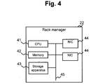
- Fig. 4 is a view showing a configuration example of a rack manager 22.
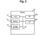
- Fig. 5 is a view showing a configuration example of a server 23.
- Fig. 6 is a view showing a configuration example of a management switch.
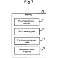
- Fig. 7 is a view showing an example of a program and the information that are stored by a memory 12 of the management server 10.
- Fig. 8 is a view showing an example of a program and the information that are stored by a memory 42 of the rack manager 22.
- Fig. 9 is a view showing an example of a program and the information that are stored by a memory 52 of the server 23.
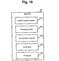
- Fig. 10 is a view showing an example of a program and the information that are stored by a memory 62 of the management switch 25.
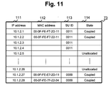
- Fig. 11 is a view showing a configuration example of an IP address management table 73.
- Fig. 12 is a view showing a configuration example of an IP address table 83.
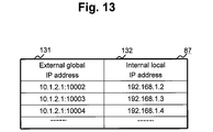
- Fig. 13 is a view showing a configuration example of a NAT table 87.
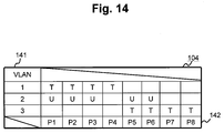
- Fig. 14 is a view showing a configuration example of a VLAN table 104.
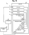
- Fig. 15 is a view showing a first part of an example of a processing flow that is executed in the case in which the SU 20 is added to the computer system 1.
- Fig. 15 is a view showing a first part of an example of a processing flow that is executed in the case in which the SU 20 is added to the computer system 1.
- Fig. 15 is a
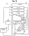
- FIG. 16 is a view showing a second part of an example of a processing flow that is executed in the case in which the SU 20 is added to the computer system 1.
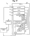
- Fig. 17 is a view showing a third part of an example of a processing flow that is executed in the case in which the SU 20 is added to the computer system 1.
- Fig. 18 is a view showing a remaining part of an example of a processing flow that is executed in the case in which the SU 20 is added to the computer system 1.
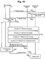
- Fig. 19 is a sequence drawing showing a flow of an example of a processing that is executed in the case in which the SU 20 is added to the computer system 1.
- Fig. 20 is a sequence drawing showing an example of a flow of a part of a processing (a processing related to the server 23) of the step 1905 of Fig. 19.
- Fig. 21 is a sequence drawing showing an example of a flow of a part of a processing (a processing related to the server 23) of the step 1905 in accordance with an embodiment 2 of the present invention.
- Fig. 22 is a sequence drawing showing an example of a flow of a part of a processing (a processing related to the server 23) of the step 1905 in accordance with an embodiment 3 of the present invention.
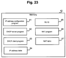
- Fig. 23 is a view showing a configuration example of the memory 42 of the rack manager 22 in accordance with an embodiment 4 of the present invention.
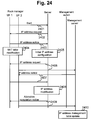
- FIG. 24 is a sequence drawing showing an example of a flow of a part of a processing (a processing related to the server 23) of the step 1905 in accordance with an embodiment 4 of the present invention.
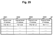
- Fig. 25 is a view showing a configuration example of a NAT table 87 in accordance with an embodiment 5 of the present invention.
- an ID identifier
- a name or a number can also be used as the identification information.
- a "program” is handled as a subject in some cases.
- the processor executes the predetermined processing by using a storage resource (such as a memory) and/or a communication interface apparatus (such as a communication port) as it decides proper. Consequently, a subject of a processing can also be a processor.
- the processing that is described while a program is handled as a subject can also be a processing that is executed by a management server or a rack manager.
- the controller can include a hardware circuit that executes a part or a whole of a processing as substitute for or in addition to a microprocessor such as a CPU.
- a computer program can be installed from a program source to each of the computers (such as a rack manager and a management server).
- the program source can be a program distribution server or a storage medium that can be read by a computer for instance.
- a management computer can also be at least one computer.
- a management computer indicates the information or a management computer transmits the information for an indication to a remote computer
- one computer is a management computer.
- the plurality of computers is a management computer (the plurality of computers can include a computer for an indication in the case in which a computer for an indication executes an indication).
- a management server and a rack manager are both management computers.
- Fig. 1 is a view showing a configuration example of a computer system in accordance with an embodiment 1.
- the computer system 1 includes at least one SU (Scale Unit) 20, and a plurality of communication apparatuses in the at least one SU 20 is managed by a management server 10.
- the management server 10 and each of the SU 20 are coupled to each other via a management network (such as a LAN (Local Area Network)) 2 in such a manner that a packet communication can be executed.
- a management network such as a LAN (Local Area Network)
- Each of the SU 20 is coupled to each other via a communication network (such as an FC (Fibre Channel) network) 3 in such a manner that a packet communication can be executed.
- FC Fibre Channel
- the management network 2 is a communication network that is used for a purpose of managing a communication apparatus in the SU 20 by the management server 10.
- the management network 2 is configured by a switch or a router for instance.
- the communication network 3 is also configured by a switch or a router for instance.
- the communication network 3 is a communication network that is used for a communication between communication apparatuses in different SUs 20.
- the management server 10 is a server that is configured to manage the whole of the computer system 1.
- the SU 20 is a computer subsystem (an apparatus group) that is configured by a server, a storage, and a network apparatus that have already been coupled for instance.
- Fig. 2 is a view showing a configuration example of the management server 10.
- the management server 10 is provided with a CPU (Central Processing Unit) 11, a memory 12, a storage apparatus 13, a NIC 14, and a bus 15.
- a communication medium that is configured to couple the CPU 11, the memory 12, the storage apparatus 13, and the NIC 14 to each other is not restricted to the bus 15, and a communication medium of other type can also be adopted. This is not restricted to the management server 10.
- This is similar to a communication apparatus of other type (such as at least one type of apparatuses of a rack manager 22, a server 23, and a management switch 25).
- the CPU 11 executes a program that has been stored into the memory 12.
- the memory 12 stores a program and data that are executed by the CPU 11.
- the storage apparatus 13 is a physical storage apparatus that is configured to store data, and is an HDD (Hard Disk Drive) or an SSD (Solid State Drive) for instance.
- the NIC (Network Interface Card) 14 is a type of a communication interface apparatus, and is an expansion card that is configured to transmit and receive a packet via a network cable.
- the NIC 14 is coupled to the management network 2.
- the bus 15 is a transmission path that is configured to transmit and receive a signal between the CPU 11, the memory 12, the storage apparatus 13, and the NIC 14.
- the management server 10 manages an IP address that has been allocated to a communication apparatus in the SU 20.
- the management server 10 notifies each of communication apparatuses in the added SU 20 of an IP address that is to be allocated by communicating with the communication apparatus in the added SU 20.
- Fig. 3 is a view showing a configuration of the SU 20.
- the SU 20 is provided with a plurality of communication apparatuses and a rack manager 22 that is coupled to the plurality of communication apparatuses.
- a ToR (Top of Rack) switch 21 As the plurality of communication apparatuses, there can be mentioned for instance a ToR (Top of Rack) switch 21, a server 23, a storage 24, and a management switch 25.
- ToR Topic of Rack
- the server 23 and the storage 24 are coupled to the ToR switch 21 and the management switch 25 via a management cable.
- the adding of a communication apparatus to the computer system 1 and the removal of a communication apparatus from the computer system 1 are not executed in a unit of a communication apparatus but executed in a minimum unit of the SU 20.
- the ToR switch 21 is a packet relay apparatus that is configured to couple a communication apparatus in the SU 20 to the communication network 3.
- the communication between SUs 20 via the communication network 3 is executed via the ToR switch 21.
- the rack manager 22 is a computer that is configured to manage each of the communication apparatuses in the SU 20.
- the server 23 is a computer that is configured to execute an application program.
- the server 23 receives a command from a communication apparatus inside or outside the SU 20 that is provided with the server 23, and processes the command.
- the server 23 transmits an I/O (Input/Output) command based on the write command or the read command to the storage 24.
- I/O Input/Output
- the storage 24 is a physical storage apparatus that is configured to store the data that is conforms to an I/O command from the server 23 and a computer program (such as an application program and an OS (Operating System)) that is executed by the server 23.
- the storage 24 can be a single storage medium (such as an HDD and an SSD) and a storage apparatus that is provided with a plurality of storage media (such as a disk array apparatus).
- the management switch 25 is a packet relay apparatus that is configured to couple each of the communication apparatuses in the SU 20 to the management network 2.
- the SU 20 shown in the figure can be provided with or is not provided with at least one type of communication apparatuses of the ToR switch 21, the rack manager 22, the server 23, the storage 24, and the management switch 25. Moreover, the SU 20 can be provided with a plurality of communication apparatuses of at least one type of the plurality of types of communication apparatuses.
- Fig. 4 is a view showing a configuration example of the rack manager 22.
- the rack manager 22 is provided with a CPU 41, a memory 42, a storage apparatus 43, a NIC 44, and a bus 45.
- the CPU 41 is coupled to the memory 42, the storage apparatus 43, and the NIC 44 via the bus 45. Since the configuration of the rack manager 22 is almost equivalent to that of the management server 10 described above, the descriptions of the configuration elements of the rack manager 22 are omitted.
- a function that is configured to manage each of the communication apparatuses in the SU 20 can be implemented by executing a program that has been stored into the memory 42 by the CPU 41.
- the program can be stored into any of the communication apparatuses (such as a memory of the storage 24, the management switch 25, the server 23, and the ToR switch 21) as substitute for the rack manager 22, and can be executed by a processor in any of the communication apparatuses. In other words, any of the communication apparatuses can be operated as the rack manager 22.
- Fig. 5 is a view showing a configuration example of the server 23.
- the server 23 is provided with a CPU 51, a memory 52, a storage apparatus 53, a NIC 54, and a bus 55.
- the CPU 41 is coupled to the memory 42, the storage apparatus 43, and the NIC 44 via the bus 45. Since the configuration of the server 23 is almost equivalent to that of the management server 10 described above, the descriptions of the configuration elements of the server 23 are omitted.
- the NIC 54 is configured by a NIC 54a that is configured to be coupled to the communication network 3 and a NIC 54b that is configured to be coupled to the management network 2.
- the NIC 54a and the NIC 54b can also be configured in an integrated manner, and the ToR switch 21 and the management switch 25 can also be configured in an integrated manner.
- a VLAN Virtual LAN (Local Area Network)
- a VLAN that is corresponded to the ToR switch 21 and a VLAN that is corresponded to the management switch 25 can also be configured to a single switch.
- Fig. 6 is a view showing a configuration example of the management switch 25.
- the management switch 25 is provided with a CPU 61, a memory 62, an NVRAM (Non Volatile RAM) 63, a buffer 64, and a plurality of ports 65, and a bus 66.
- NVRAM Non Volatile RAM
- the CPU 61 executes a program that has been stored into the memory 62.
- the memory 62 is a main storage memory for instance, and stores a program and data that are executed by the CPU 61.
- the NVRAM 63 is an auxiliary storage memory for instance, and stores the data that has been stored into the memory 62 on a long term basis.
- the buffer 64 is a storage region that is configured to store a packet that is transmitted or received at the port 65 on a temporary basis.
- the port 65 is an interface that is configured to transmit or receive a packet.
- the port 65 can be a physical port or a logical port.
- Fig. 7 is a view showing an example of a program and the information that are stored by the memory 12 of the management server 10.
- the memory 12 of the management server 10 stores an IP address allocation program 71, a DHCP server program 72, an IP address management table 73, and a management server IP address 74.
- the IP address allocation program 71 receives an IP address allocation request that is a request of allocating an IUP address to a communication apparatus (hereafter referred to as an added apparatus) that configures an SU (hereafter referred to as an added SU) 20 that has been added to the computer system from the rack manager 22, the IP address allocation program 71 executes the following processing: (*) decides an IP address that is suitable for an added apparatus based on the IP address management table 73; and (*) notifies the rack manager 22 of the suitable IP address that has been decided.
- the DHCP server program 72 is a program that is configured to notify an IP address in accordance with a request from a DHCP client program 83 that is executed by the rack manager 22 in the added SU 20.
- the IP address is an address that is used for a communication at an initial stage between the rack manager 22 and the management server 10. By using the IP address, a new IP address is allocated to each of the added apparatuses. It is also possible that the DHCP server program 72 is not disposed. In the case in which the DHCP server program 72 is not disposed, a configuring work of an IP address that is used for a communication at an initial stage described above is carried out manually by a manager.
- the IP address management table 73 is a table that is provided with the information that indicates an IP address that has been allocated to each of the communication apparatuses in the computer system 1.
- the management server IP address 74 is the information that indicates an IP address that has been allocated to the NIC 14 of the management server 10.
- Fig. 8 is a view showing an example of a program and the information that are stored by the memory 42 of the rack manager 22.
- the memory 42 of the rack manager 22 stores an IP address configuration program 81, a DHCP server program 82, a DHCP client program 83, an IP address table 84, and an SU ID 85.
- the IP address configuration program 81 is a program that is configured to execute the following processing in the case in which the IP address configuration program 81 adds an SU 20 to the computer system 1: (*) issues a request of a suitable IP address that is to be allocated to an added apparatus to the management server 10; and (*) configures the IP address that has been notified by the management server 10 to each of the added apparatuses.
- the DHCP server program 82 is a program that is configured to notify an IP address in accordance with a request from a DHCP client program 83 that is executed by the rack manager 22 in the added SU 20.
- the IP address is an address that is used for a communication at an initial stage between the rack manager 22 and the management server 10.
- the DHCP client program 83 is a program that is configured to request an IP address that is to be allocated to the NIC 44 of the rack manager 22 for instance to the DHCP server program 72 that is executed by the management server 10.
- the IP address is also an address that is used for a communication at an initial stage between the rack manager 22 and the management server 10. It is also possible that the DHCP server program 82 and the DHCP client program 83 are not disposed.
- the IP address table 84 is a table that is provided with the information that indicates an IP address that has been allocated to the NIC 44 that is included in the rack manager 22.
- the SU ID 85 is an ID of the SU 20 that stores the ID 85.
- Fig. 9 is a view showing an example of a program and the information that are stored by the memory 52 of the server 23.
- the memory 52 of the server 23 stores a command reception program 91, a DHCP client program 92, and an IP address table 93.
- the command reception program 91 is a program that is configured to receive and execute a command that has been transmitted from the rack manager 22.
- the DHCP client program 92 is a program that is configured to request an IP address that is to be allocated to the NIC 54 that is included in the server 23 to the DHCP server program 82 that is executed by the rack manager 22. It is also possible that the DHCP client program 92 is not disposed.
- the communication apparatus of other kind in addition to the server 23 can also be provided with the command reception program 91, the DHCP client program 92, and the IP address table 93.
- a processing that is similar to a processing that is executed in the case in which an IP address is configured to the server 23 can also be executed by a communication apparatus of other kind.
- Fig. 10 is a view showing an example of a program and the information that are stored by the memory 62 of the management switch 25.
- the memory 62 of the management switch 25 stores a packet transfer program 101, a forwarding table 102, a configuration program 103, a VLAN table 104, and a plurality of IP addresses 105.
- the packet transfer program 101 is a program that is configured to execute the following processing based on the forwarding table 102: (*) searches a port 65 that is a transfer destination of the received packet and transfers the received packet to the found port 65 of a transfer destination; and (*) updates the forwarding table 102 based on a MAC address that is a transmission source of the received packet.
- the forwarding table 102 is a table that is provided with the information that indicates the correspondence relationship between the MAC address and a transfer destination port.
- the configuration program 103 is a program that is configured to manage a VLAN.
- the configuration program 103 uses a VLAN table 104 (see Fig. 14) for managing a VLAN.
- the VLAN table 104 is a table that indicates the correspondence relationship between a VLAN and a port.
- the plurality of IP addresses 105 is IP addresses that have been allocated to a plurality of ports 65 that are included in the management switch 25.
- Fig. 11 is a view showing a configuration example of an IP address management table 73.
- the IP address management table 73 is provided with an IP address 111, a MAC address 112, an SU ID 113, and a state 114 for every IP address that is managed by the management server 10 (a management IP address in the description of Fig. 11).
- the IP address 111 is the information that indicates a management IP address.
- the MAC address 112 is the information that indicates a MAC address of a communication apparatus to which a management IP address has been allocated. In the case in which a communication apparatus has not been allocated, it is possible that the MAC address 112 is not registered to the table 73.
- the SU ID 113 is an ID of the SU 20 to which a communication apparatus to which a management IP address has been allocated belongs.
- the state 114 is the information that indicates a state of a management IP address: (*) in the case in which a management IP address has been allocated to an added apparatus, a value of the state 114 is "coupled”; (*) in the case in which a management IP address has already been notified an added SU 20 of and the management IP address has not been allocated to a communication apparatus in the added SU 20, a value of the state 114 is "under configuration”; and (*) in the case in which a management IP address has not been notified an SU 20, a value of the state 114 is "unallocated".
- Fig. 12 is a view showing a configuration example of an IP address table 83.
- the IP address table 83 is provided with an I/F ID 121, a NIC ID 122, an IP address 123, and a VLAN tag 124 for every I/F (interface).
- the I/F ID 121 is an ID of an I/F (interface).
- the I/F is a virtual end point of an IP communication that is identified by an IP address (a virtual communication interface apparatus that is configured to the NIC 44), the I/F can also be a physical communication interface apparatus. At least one I/F can be configured to one NIC.
- the NIC ID 122 is an ID of a NIC to which an I/F has been configured.
- the IP address 123 is the information that indicates an IP address that is allocated to an I/F.
- the VLAN tag 124 is the information that indicates a tag that is added to a packet that is transmitted by an I/F. In the case in which a tag is not added, it is possible that a value of the VLAN tag 124 is "none".
- An I/F can communicate with a VLAN that is corresponded to a VLAN tag that has been added to the I/F. More specifically, the I/F to which a VLAN tag "1" has been added can communicate via the VLAN 1 and cannot communicate via other VLAN.
- the VLAN is a virtual LAN that has been coupled to the port 65 of the management switch 25. At least one VLAN can be formed in the management switch 25.
- Fig. 14 is a view showing a configuration example of a VLAN table 104.
- the VLAN table 104 is provided with a VLAN 141 and ports (P1 to P8) 142.
- the VLAN table 104 is provided with the information that indicates a port 65 and a VLAN to which the port 65 belongs and the information that indicates whether or not a packet that is transmitted from the port 65 is VLAN tagged.
- the VLAN table 104 is the information for identifying a VLAN, and is a number as a VLAN tag for instance.
- the ports (P1 to P8) 142 are the information that indicates which VLAN each of the ports belongs to.
- (*) "U” represents that a VLAN is not a tag VLAN (a VLAN in which a tag is inserted to a packet that is input or output).
- a VLAN2 is an untagged VLAN (that is, not a tag VLAN) and the ports P1 to P3, P5 and P6 belong to the VLAN2; and
- (*) "T” represents that a VLAN is a tag VLAN.
- a VLAN1 and a VLAN3 are tag VLANs, the ports P1 to P4 belong to the VLAN1, and the ports P5 to P8 belong to the VLAN3.
- One port 65 belongs to a plurality of VALNs in some cases.
- the port P1 belongs to both of the VLAN1 and the VLAN2 as described above.
- a tag "1" is inserted to a packet that is transmitted from the port P1 to the VLAN1, and a tag is not inserted to a packet that is transmitted from the port P1 to the VLAN2.
- the SU 20 described above is a computer system of one type and can be operated in a stand alone manner.
- the server 23 can receive an I/O request from a client computer not shown, and can execute an I/O of data to the storage 24 via the management switch 25 in accordance with the I/O request.
- the rack manager 22 can manage each of the communication apparatuses 21, 23, 24, and 25 in the SU 20.
- a computer system 1 of a large scale that is provided with a plurality of the SUs 20 can be constructed.
- the SU 20 is a computer subsystem for the computer system 1.
- the rack manager 22 in the SU 20 is provided with an authority for managing the communication apparatuses 21, 23, 24, and 25.
- an authority for managing the communication apparatuses 21, 23, 24, and 25 is transferred from the rack manager 22 in the added SU 20 to the management server 10.
- the management server 10 manages a plurality of communication apparatuses in at least one SU 20 for the computer system 1 in an integrated fashion in the present embodiment.
- an SU that is added to the computer system 1 is referred to as an added SU in some cases.
- a communication apparatus inside an added SU is referred to as an internal apparatus in some cases, and a communication apparatus outside an added SU is referred to as an external apparatus in some cases.
- the computer system 1 is provided with at least one existing SU 20, and a communication apparatus (such as the server 23 and the storage 24) in the existing SU 20 is a management target of the management server 10.
- a communication apparatus such as the server 23 and the storage 24
- an SU 20 is newly added to the computer system 1. More specifically, the ToR switch 20 of the SU 20 is coupled to the network 3, and the port P1 of the management switch 5 is coupled to the network 2.
- the SU 20 is initially in the following state: (*)
- the VLAN1 is configured to the management switch 25.
- the VLAN1 is a tag VLAN.
- the ports P1 to P5 belong to the VLAN1.
- the port P1 is a port that is coupled to the management server 10.
- the port P2 is a port that is coupled to the rack manager 22.
- the ports P3 to P5 are ports that are used to communicate with a plurality of internal apparatuses (a plurality of internal apparatuses 21, 23, and 24 other than the management switch 25 and the rack manager 22).
- the I/F 1 is configured to the NIC 44 that is included in the rack manager 22.
- the I/F 1 is a virtual communication interface apparatus.
- An initial IP address is allocated to the I/F 1.
- an initial IP address is allocated to a plurality of communication apparatuses 21 and 22.
- An initial IP address is an IP address that has been assigned in advance (for instance, from the beginning of a shipment), and is an IP address that is used to communicate with the communication apparatuses 21, 23, and 24 by the rack manager 22.
- the storage resource (such as the memory 42) of the rack manager 22 has stored the information that indicates the initial IP address of a plurality of internal apparatuses 21 to 24 in advance.
- the VLAN1, the rack manager 22, and the plurality of internal apparatuses 21, 23, and 24 belong to the same subnet. More specifically, a network address of the initial IP address of the I/F 1 is equivalent to a network address of the initial IP address of the internal apparatuses 21, 23, and 24.
- the rack manager 22 can communicate with the internal apparatuses 21, 23, and 24 via the VLAN1.
- the added SU 20 can be coupled to the management server 10 in such a manner that the added SU 20 can communicate with the management server 10. More specifically, the following processing is executed for instance: (*) The rack manager 22 uncouples the port P1 from the VLAN1. The coupling and uncoupling of a port and a VLAN are executed by transmitting a coupling modification command to the management switch 25 by the rack manager 22 and by executing the coupling modification command by the management switch 25 for instance.
- the coupling modification command is a command for modifying a correspondence relationship between a port and a VLAN. In the case in which the coupling modification command is executed, the management switch 25 updates the VLAN table 104 for instance.
- the rack manager 22 configures the VLAN2 to the management switch 25.
- a line that is corresponded to the VLAN2 is added to the VLAN table 104.
- the VLAN2 is an untagged VLAN (that is, a VLAN that is not a tag VLAN).
- the VLAN2 can be configured to the management switch 25 in advance similarly to the VLAN1.
- the VLAN2 can also be a tag VLAN to which a tag that is different from a tag that is assigned in a communication via the VLAN1 and a VLAN3 described later is assigned.
- the VLAN2 is not a VLAN that is used for a communication between internal apparatuses but a VLAN that is used for a communication with an external apparatus (the management server 10). Consequently, it is preferable that the VLAN2 is an untagged VLAN like the present embodiment.
- the rack manager 22 makes the port P1 and the port P2 to belong to the VLAN2. By this configuration, "U" is set to a cell that is corresponded to the port P1, the port P2, and the VALN2 for the VLAN table 104.
- the port P2 belongs to both of the VLAN1 and the VLAN2.
- the rack manager 22 configures the I/F 2 to the NIC 44.
- the I/F 2 is a virtual communication interface apparatus similarly to the I/F 1.
- An IP address of the I/F 2 is allocated to the I/F 2.
- the IP address can be an IP address that has been input by a human person such as a manager or can be an IP address that has been input automatically (for instance, an IP address that has been input in accordance with a technique of the DHCP).
- the I/F 2 and an IP address of the I/F 2 can be configured to the rack manager 22 in advance similarly to the I/F 1 and an IP address of the I/F 1.
- a configuration of an IP address to the I/F 2 can be carried out by an execution of a command or can be carried out by a rewrite of a configuration file and a restart of an I/F.
- the configuration file is a file that is used in a communication by the rack manager 22, and is a file that has been stored into a storage resource (such as the storage apparatus 43) in the rack manager 22.
- the storage resource (such as the memory 42) of the rack manager 22 stores the information that indicates an IP address of the management server 10.
- the IP address can be an IP address that has been input by a human person such as a manager or can be an IP address that has been input automatically (for instance, an IP address that has been input in accordance with a technique of the DHCP).
- the rack manager 22 can communicate with the management server 10 via the VLAN2.
- the management server 10 transmits a plurality of appropriate IP addresses to the rack manager 22, and the rack manager 22 configures the plurality of appropriate IP addresses to the I/F 3 and the internal apparatuses 21, 23, and 24.
- the management server 10 and the internal apparatuses 21, 23, and 24 can communicate with each other. More specifically, the following processing is executed for instance: (*) The rack manager 22 configures the VLAN3 to the management switch 25. By this configuration, a line that is corresponded to the VLAN3 is added to the VLAN table 104. (*) The VLAN2 and the VLAN3 belong to the same subnet.
- a network address of an IP address that is used for a communication via the VLAN2 is equivalent to a network address of an IP address that is used for a communication via the VLAN3 (an appropriate IP address that is transmitted from the management server 10 and that is configured to each of the internal apparatuses by the rack manager 22).
- a subnet to which the management server 10 belongs is equivalent to a subnet to which the internal apparatus belongs (a subnet to which the VLAN3 belongs).
- it is not preferable that a plurality of internal apparatuses is initially coupled to the VLAN2 to which the external apparatus (the management server 10) is coupled.
- the rack manager 22 can distinguish and transmit packets in such a manner that "a packet that is transmitted without a VLAN tag is for the external apparatus" and "a packet that is transmitted with a VLAN tag is for the internal apparatus".
- the rack manager 22 configures the I/F 3 in the NIC 44.
- the I/F 3 is a virtual communication interface apparatus similarly to the I/F 1 and the I/F 2.
- the rack manager 22 transmits an appropriate IP request from the I/F 2.
- the appropriate IP request is transmitted to the management server 10 via the VLAN2 and the port P1.
- the appropriate IP request is a request of an allocation of an appropriate IP address.
- the request can include the information that indicates the required number of appropriate IP addresses.
- the appropriate IP address is a static IP address, and is an IP address that is used to communicate with the communication apparatuses 21, 23, and 24 by the management server 10.
- the management server 10 receives the appropriate IP request and transmits a plurality of appropriate IP addresses to the rack manager 22 in response to the request. In accordance with the example shown in Fig. 17, five appropriate IP addresses are necessary. This is because a plurality of appropriate IP addresses is allocated to the I/F 3 and the communication apparatuses 21, 23, 24, and 25.
- the management server 10 receives a plurality of appropriate IP addresses that have been transmitted from the management server 10 by the I/F 2 via the port P1, the VLAN2, and the port P2.
- the rack manager 22 couples the port P2 to which the I/F 1 and the I/F 2 are coupled to the VLAN3. Moreover, the rack manager 22 couples the ports P3 to P5 to which the internal apparatuses 21, 23, and 24 are coupled to the VLAN3. By this configuration, "T" is set to a cell that is corresponded to the ports P2 to P5 and the VALN3 for the VLAN table 102.
- the rack manager 22 logs in the management switch 25 from the I/F 1.
- the rack manager 22 configures the above plurality of appropriate IP addresses to the I/F 3 and the internal apparatuses 21, 23, 24, and 25 via the VLAN1.
- the IP address of the internal apparatuses 21, 23, 24, and 25 is modified from an initial IP address to an appropriate IP address.
- the rack manager 22 transmits an IP configuration command from the I/F 1 to the internal apparatus and the internal apparatus executes the IP configuration command
- the IP address of the internal apparatus is modified from an initial IP address to an appropriate IP address.
- the IP configuration command is a command for configuring an IP address.
- the rack manager 22 checks whether or not a communication apparatus in the added SU 20 is coupled to the rack manager 22 in such a manner that the added SU 20 can communicate with the rack manager 22 (hereafter referred to as a coupling check) from the I/F 3 via the port 2 and the VLAN3 for every internal apparatus to which an appropriate IP address has been configured.
- a coupling check for the internal apparatus in which a result of the above coupling check is positive, the rack manager 22 transmits an allocation completion notice of an IP address (a notice of that an appropriate IP address has been configured) to the management server 10 from the I/F 2 via the port 2 and the VLAN2.
- the rack manager 22 can notify the management server 10 of a configuration modification failure from the I/F 2 via the port 2 and the VLAN2. Moreover, for the internal apparatus in which a result of the above coupling check is negative, the rack manager 22 can configure an appropriate IP address that has been configured to the internal apparatus to the internal apparatus again, and can execute the above coupling check for the internal apparatus again. In the case in which a result of the above coupling check is negative even in the case in which the processing is executed a predetermined number of times (for instance at least one time) for instance, the rack manager 22 can notify the management server 10 of a configuration modification failure from the I/F 2 via the port 2 and the VLAN2.
- the storage resource (such as the memory 12) of the management server 10 has stored the information that indicates a plurality of appropriate IP addresses that has been transmitted to the rack manager 22 for an IP address of the I/F 2 of the rack manager 22 in the added SU 20 for instance.
- the management server 10 writes the information that indicates whether or not a configuration modification completion of an IP address is received for every appropriate IP address into the storage resource (such as the memory 12) in the management server 10.
- the information that indicates a configuration modification completion is stored into the storage resource (such as the memory 12) in the management server 10 for the internal apparatus that is corresponded to the allocation completion notice.
- the information that indicates a configuration modification failure is stored into the storage resource (such as the memory 12) in the management server 10 for the internal apparatus that is corresponded to the configuration modification failure.
- the management server 10 can decide another appropriate IP address for the internal apparatus that is corresponded to the configuration modification failure, and can transmit an IP configuration command for configuring the appropriate IP address to the internal apparatus that is corresponded to the configuration modification failure to the rack manager 22.
- the IP configuration command is received by the I/F 2 via the port P1, the VLAN2, and the port P2.
- the rack manager 22 configures another appropriate IP address to the internal apparatus that is corresponded to the configuration modification failure in response to the IP configuration command, and executes the above check for the internal apparatus.
- a management authority of all the internal apparatuses is transferred from the rack manager 22 to the management server 10 as shown in Fig. 18. More specifically, the following processing is executed for instance: (*) The rack manager 22 removes the VLAN1 and the VLAN2 from the management switch 25. By this configuration, a line that is corresponded to the VLAN1 and the VLAN2 is deleted from the VLAN table 102. (*) The rack manager 22 removes the I/F 1 and the I/F 2 from the NIC 44. The I/F 3 can also be removed as substitute for the I/F 2. (*) The rack manager 22 couples the port P1 that has been coupled to the management server 10 to the VLAN3. By this configuration, "T" is set to a cell that is corresponded to the port P1 and the VALN3 for the VLAN table 102.
- all the internal apparatuses 21 to 25 are coupled to the management server 10 via the VLAN3, and the management server 10 can manage all the internal apparatuses 21 to 25 via the port P1 and the VALN3.
- a management authority of the internal apparatuses 21, 23, 24, and 25 that have been managed by the rack manager 22 and a management authority of the rack manager 22 are transferred to the management server 10.
- the internal apparatus 22 can be operated not as the rack manager but as a communication apparatus of other type.
- a communication apparatus of other type is an SVP (Service Processor) that is a maintenance terminal of the storage 24.
- a communication apparatus of other type can also be a communication apparatus such as a server and a storage.
- a hardware resource of the internal apparatus 22 that is operated as the rack manager that is, an internal management computer that is configured to manage the internal apparatuses 21, 23, 24, and 25
- a management authority is transferred can be utilized in an effective manner.
- Fig. 19 is a sequence drawing showing a flow of an example of a processing that is executed in the case in which the SU 20 is added to the computer system 1.
- An IP address configuration program 81 in the rack manager 22 transmits an appropriate IP request from the I/F 2 to an IP address allocation program 71 in the management server 10 (step 1901). More specifically, the IP address configuration program 81 calculates the required number of appropriate IP addresses based on the total number of NICs that are included in a plurality of internal apparatuses in the added SU 20 for instance, and transmits an appropriate IP request that includes the information that indicates the number to the IP address allocation program 71 in the management server 10.
- the IP address allocation program 71 receives the appropriate IP request and executes the following processing in response to the request (step 1902): (*) identifies an unallocated IP address (appropriate IP address) of the number that is equivalent to the required number of appropriate IP addresses based on the IP address management table 73; and (*) modifies a state 114 of the identified IP address (see Fig. 11) from "unallocated" to "under allocation".
- a plurality of appropriate IP addresses that are identified can be serial numbers.
- the IP address allocation program 71 transmits the information that indicates the plurality of appropriate IP addresses that has been identified in the step 1902 to the IP address configuration program 81 (step 1903).
- the IP address configuration program 81 receives the information that has been transmitted in the step 1903 and executes the following processing (step 1904): (*) configures the I/F 3 to the NIC 44 and configures one appropriate IP addresses of the plurality of appropriate IP addresses that is indicated by the information that has been transmitted to the I/F 3; and (*) adds a line that is corresponded to the I/F 3 to the IP address table 84, registers an ID of the I/F 3 to the line as an I/F ID 121, registers an ID of the NIC 44 to which the I/F 3 has been configured as a NIC ID 122, registers the information that indicates an appropriate IP address that has been configured to the I/F 3 as an IP address 123, and registers the information that indicates a tag that is added to a packet via the VLAN3 as a VLAN tag 124.
- the IP address configuration program 81 executes the following processing (step 1905): (*) configures the VLAN3 to the management switch 25 via the I/F 1; (*) couples the ports P2 to P5 to the VLAN3 via the I/F 1; and (*) configures at least two appropriate IP addresses other than the appropriate IP address that has been configured to the I/F 3 among the plurality of appropriate IP addresses that are indicated by the received information to at least two internal apparatuses 21, 23, 24, and 25.
- the IP address configuration program 81 sets the management switch 25 in such a manner that a port to which the management server is coupled among the ports of the management switch 25 belongs to the VLAN3 (step 1906).
- the IP address configuration program 81 removes the I/F 1 and the I/F 2 from the NIC 44. By this configuration, a line that is corresponded to the I/F 1 and the I/F 2 is deleted from the IP address table 84 (step 1907).
- the IP address configuration program 81 transmits a completion report to the IP address allocation program 71 (step 1908).
- a completion report can also be executed via the I/F 3 and the VLAN3.
- the IP address allocation program 71 receives the completion report, and checks whether or not a communication can be executed for the appropriate IP address that has been transmitted in the step 1903 (step 1909). The check can also be executed in accordance with a predetermined protocol (for instance, ICMP (Internet Control Message Protocol)).
- ICMP Internet Control Message Protocol
- Fig. 20 is a sequence drawing showing an example of a flow of a part of a processing (a processing related to the server 23) of the step 1905 of Fig. 19. While Fig. 20 is a drawing showing an example of the server 23 as an internal apparatus, it is possible that a configuration of the appropriate IP address to an internal apparatus of other type is completed by executing a processing similar to a processing shown in Fig. 20 for an internal apparatus of other type in the step 1905 of Fig. 19.
- the IP address configuration program 81 establishes a session for executing a command operation by using a protocol such as Telnet (Telecommunication network) to the command reception program 91 in the server 23 via the I/F 1.
- the IP address configuration program 81 transmits the IP configuration command for adding an appropriate IP address (for instance, 10.1.2.3) in addition to an initial IP address for the NIC 54 of the server 23 to the command reception program 91 in the server 23 (step 2001). It is also possible that the above operation is executed by the method in which the IP address configuration program 81 directly rewrites the IP address table 93 in the server 23 and the NIC 54 of the server 23 recognizes again the IP address table 93 that has been rewritten.
- the command reception program 91 in the server 23 executes the following processing in response to the above IP configuration command (step 2002): (*) modifies an IP address of the I/F of the NIC 54 of the server 23 from an initial IP address to an appropriate IP address (for instance, 10.1.2.3); and (*) registers the information that indicates the appropriate IP address that has been configured to the IP address table 93 in the server 23 as an IP address of the I/F of the NIC 54, and registers "3" as a VLAN tag.
- the rack manager 22 can communicate with the server 23 via the VLAN3.
- the IP address configuration program 81 establishes a session for executing a command operation by using a protocol such as Telnet to the configuration program 103 in the management switch 25 via the I/F 1.
- the IP address configuration program 81 transmits the VLAN addition command for adding the VLAN3 in the case in which the VLAN3 is not configured to the management switch 25 and transmits the coupling modification command for coupling the port P4 to which the server 23 has been coupled to the VLAN3 to the configuration program 103 (step 2003).
- the configuration program 103 updates the VLAN table 104 by executing a processing that conforms to the VLAN addition command and the coupling modification command (step 2004). Moreover, the configuration program 103 returns a response to the IP address configuration program 81 (step 2005).
- the IP address configuration program 81 receives the response via the I/F 1, and transmits a packet for a coupling check to the command reception program 91 in the server 23 via the I/F 3 (step 2006).
- the command reception program 91 receives a packet for a coupling check
- the command reception program 91 transmits a response packet to the IP address configuration program 81 (step 2007).
- This operation can be executed in accordance with the predetermined protocol for instance.
- the predetermined protocol can be an ICMP for instance.
- a packet for a coupling check can be a ping for instance.
- the IP address configuration program 81 operates to delete the IP address that has been initially set to the NIC 54 of the server 23 by using a command or the like and transmits an allocation completion notice to the IP address allocation program 71 in the management server 10 via the I/F 2 (step 2008).
- the allocation completion notice can include an appropriate IP address that has been newly allocated to the I/F of the NIC 54 of the server 23 and a MAC address of the NIC 54.
- the IP address allocation program 71 updates the IP address management table 73 (step 2009).
- the IP address allocation program 71 registers a value of a MAC address that is included in the allocation completion notice as a MAC address 112, registers an ID of the added SU 20 that includes the server 23 as the SU ID 113, and registers "coupling" (the information that indicates that an allocation has been completed) as a state 114 to a line that includes an IP address that is corresponded to an IP address that is included in the allocation completion notice (a line in the IP address management table 73).
- the rack manager 22 also configures an appropriate IP address to the internal apparatuses of other types (such as the ToR switch 21, the storage 24, and the management switch 25) in a flow that is substantially equivalent to a flow of a processing shown in Fig. 20.
- other types such as the ToR switch 21, the storage 24, and the management switch 25
- the initial IP address of each of the internal apparatuses in the SU 20 is modified to an appropriate IP address that has been supplied from the management server 10. Since the appropriate IP address that has been allocated to each of the internal apparatuses is a static IP address, the appropriate IP address is not modified after the restart. Moreover, a static IP address that can be allocated is managed by the management server 10, and a plurality of static IP addresses that are allocated to a plurality of internal apparatuses is automatically decided in response to the appropriate IP address. The plurality of static IP addresses is then automatically configured to the plurality of internal apparatuses in the flow described above. In the present the embodiment as described above, a static IP address is allocated to a communication apparatus in the SU 20 that has been added to the computer system 1 without the manual cumbersome and complicated works.
- Fig. 21 is a sequence drawing showing an example of a flow of a part of a processing (a processing related to the server 23) of the step 1905 in accordance with the embodiment 2 of the present invention.
- the IP address configuration program 81 establishes a session for executing a command operation by using a protocol such as Telnet to the configuration program 103 in the management switch 25 via the I/F 1.
- the IP address configuration program 81 transmits the VLAN addition command for adding the VLAN3 in the case in which the VLAN3 is not configured to the management switch 25 and transmits the coupling modification command for coupling the port P4 to which the server 23 has been coupled to the VLAN3 to the configuration program 103 (step 2101).
- the configuration program 103 updates the VLAN table 104 by executing a processing that conforms to the VLAN addition command and the coupling modification command (step 2102). Moreover, the configuration program 103 returns a response to the IP address configuration program 81 (step 2103).
- the IP address configuration program 81 receives the response by the I/F 1, and executes a power activation to the server 23 via the I/F 1 (step 2104). This process can be executed by using a technique such as Wake on LAN (WoL). After that, the IP address configuration program 81 deletes an interface to which an IF number "1" is added.
- a technique such as Wake on LAN (WoL).
- the DHCP client program 802 that is stored into the memory 1501 transmits an IP address allocation request to the DHCP server program 502 that is stored into the memory of the rack manager 205 (step 2105).
- the DHCP client program 92 in the server 24 transmits an IP address allocation request to the DHCP server program 82 in the rack manager 22 via the I/F 1 and the VLAN1 (step 2105).
- the DHCP server program 82 receives the IP address allocation request via the VLAN1 and the I/F 1, identifies an IP address that is to be allocated from a plurality of appropriate IP addresses that have been transmitted from the management server 10, and transmits the information that indicates the appropriate IP address that has been identified via the I/F 1 and the VLAN1 (step 2106).
- the DHCP client program 92 receives an appropriate IP address from the DHCP server program 82, and modifies an IP address of the I/F of the NIC 54 from an initial IP address to the appropriate IP address (step 2107).
- the DHCP client program 92 manages the appropriate IP address that has been configured in accordance with the technique of the DHCP as a static IP address (step 2108). After that, the DHCP client program 92 transmits a modification completion notice to the rack manager 22 (step 2109). Since the modification completion notice is transmitted in a communication using the appropriate IP address that has been configured, the IP address configuration program 81 in the rack manager 22 receives the notice via the VLAN3 and the I/F 3.
- the IP address configuration program 81 receives the notice, deletes the IP address that has been allocated to the server 23 from the DHCP client table, and transmits an allocation completion notice to the IP address allocation program 71 in the management server 10 via the I/F 2 and the VLAN2 (step 2110).
- the allocation completion notice includes an appropriate IP address that has been allocated to the I/F of the NIC 54 of the server 23 and a MAC address of the NIC 54.
- the IP address allocation program 71 executes a processing similar to a processing of the step 2009 of Fig. 20 (step 2111).
- an appropriate IP address can be configured to an internal apparatus without directly operating an internal apparatus using a command or the like by the rack manager 22.
- a DHCP forwarder (not shown) in the management switch 25 is made to be effective and the DHCP server program 72 in the management server 10 allocates an IP address to each of the internal apparatuses.
- Fig. 22 is a sequence drawing showing an example of a flow of a part of a processing (a processing related to the server 23) of the step 1905 in accordance with the embodiment 3 of the present invention.
- the IP address configuration program 81 transmits a part related to the server 23 for the information that is included in the IP address table 84 to the server 23 via the I/F 1 when the NIC 54 of the server 22 is started (step 2201).
- the information part that is included in the IP address table 84 is a file.
- the command reception program 91 in the server 23 functions as a server program of a file transfer protocol such as an FTP server and an HTTP server. Consequently, the IP address configuration program 81 can execute the step 2201 by functioning as a client program of a file transfer protocol such as an FTP client and an HTTP client.
- the IP address configuration program 81 restarts the NIC 54 of the server 22 (step 2202).
- the steps 2203 to 2209 that follows the step 2202 are equivalent to the steps 2003 to 2009 in the embodiment 1 (see Fig. 20).
- an appropriate IP address can be configured to an internal apparatus without directly operating an internal apparatus using a command or the like by the rack manager 22.
- the rack manager 205 Since the IP addresses that have been added to the interfaces that are identified by the IF numbers "2" and "3" belong to the same subnet in the embodiment 1, it is necessary that the rack manager 205 specifies an interface that transmits a packet in a packet transmission. However, there is only interfaces to which the IF numbers "1" and "2" are added and these belong to separate subnets in the present embodiment, it is not necessary that the rack manager 205 specifies an interface in a packet transmission, whereby a processing can be simplified.
- Fig. 23 is a view showing a configuration example of the memory 42 of the rack manager 22 in accordance with the embodiment 4 of the present invention.
- the memory 42 of the rack manager 22 in accordance with the embodiment 4 stores a NAT (Network Address Translation) program 86 and a NAT table 87.
- NAT Network Address Translation
- the NAT program 86 is a program that is configured to implement a function for sharing an external IP address (a global IP address) by a plurality of communication apparatuses.
- the NAT program 86 transparently executes a mutual conversion of an internal IP address (an IP address that is effective only in the predetermined group (such as a corporate enterprise)) and an external IP address.
- the NAT table 87 is provided with the information that indicates the correspondence relationship between a plurality of external IP addresses and a plurality of internal IP addresses.
- Fig. 13 is a view showing a configuration example of the NAT table 87.
- the external global IP address 131 is the information that indicates an external IP address, more specifically, the information that includes an address and a TCP port that are used by the rack manager 22 as a representative of an internal apparatus in the case in which the rack manager 22 relays a communication between an internal apparatus and an external apparatus (the management server 10).
- the internal local IP address 132 is the information that indicates an internal IP address, that is, the information that indicates an IP address that has been allocated to the internal apparatus as a practical matter.
- Fig. 24 is a sequence drawing showing an example of a flow of a part of a processing (a processing related to the server 23) of the step 1905 in accordance with the embodiment 4 of the present invention.
- the rack manager 22 transmits a start command for starting the server 23 from the I/F 1 to the server 23 (step 2401).
- the DHCP client program 92 in the server 23 transmits an IP address allocation request to the DHCP server program 82 in the rack manager 22 (step 2402).
- the DHCP server program 82 receives the IP address allocation request via the VLAN1 and the I/F 1, identifies an IP address that is to be allocated from a plurality of appropriate IP addresses that have been transmitted from the management server 10, and transmits the information that indicates the appropriate IP address that has been identified via the I/F 1 and the VLAN1 (step 2403).
- the NAT program 86 adds an entry to the NAT table 87 (step 2404).
- an internal IP address "192.168.1.2” is allocated to the server 23, and an external IP address that is corresponded to the internal IP address is "10.1.2.1:10002".
- the server 23 is a transmission source and the NAT program 86 receives a packet of which a destination is the management server 10 at the transmission source IP address of "192.168.1.2”
- the NAT program 86 rewrites the transmission source IP address to be "10.1.2.1”
- rewrites the transmission source TCP port number to be "10002” and transmits the packet to the management server 10.
- the management server 10 is a transmission source and the NAT program 86 receives a packet of which a destination is the server 23 at a destination IP address of "10.1.2.1” and a destination TCP port of "10002", the NAT program 86 rewrites the destination IP address to be "192.168.1.2", and transmits the packet to the server 23.
- the server 23 can execute a reception and a transmission of a packet with the management server 10 via a NAT function of the rack manager 22.
- the DHCP client program 92 in the server 23 receives an IP address from the rack manager 22, the DHCP client program 92 configures the IP address to the I/F of the NIC 54 (step 2405).
- the step 2406 is executed. That is, the DHCP client program 92 in the server 23 transmits an IP address request to the DHCP server program 82 in the rack manager 22. The IP address request is received via the I/F 1. The DHCP client program 83 in the rack manager 22 then transmits an IP address request to the DHCP server program 72 in the management server 10 via the I/F 2.
- the step 2407 is executed. That is, the DHCP server program 72 in the management server 10 receives the IP address request, and identifies an IP address in the state 114 of "unallocated” based on the IP address management table 73.
- the DHCP server program 72 modifies the state 114 that is corresponded to the identified IP address from "unallocated” to "under allocation", and transmits the information that indicates the identified IP address to the DHCP client program 83 in the rack manager 22.
- the information is received via the I/F 2.
- the DHCP server program 82 in the rack manager 22 then transmits the information that has been received via the I/F 2 (the information that indicates the identified IP address) to the DHCP client program 92 in the server 23 via the I/F 1.
- the DHCP client program 92 in the server 23 receives the information, and modifies an IP address of the I/F of the NIC 54 (54a or 54b) of the server 23 from an initial IP address to an IP address that is indicated by the received information (the identified IP address) (step 2408).
- the step 2409 is executed. That is, the DHCP client program 92 transmits an allocation completion notice to the DHCP server program 82 in the rack manager 22. The allocation completion notice is received via the I/F 1. The DHCP client program 83 in the rack manager 22 then transmits the allocation completion notice to the DHCP server program 72 in the management server 10 via the I/F 2.
- step 2410 a processing similar to the step 2009 shown in Fig. 20 is executed (step 2410).
- an IP address that is to be allocated can be a common external IP address. Consequently, it can be expected that a static IP address that is supplied to the SU 20 is prevented from being depleted.
- the I/F that is formed in the NIC 44 of the rack manager 22 is not a virtual communication interface but a physical communication interface.
- the management switch 25 is not a management target of the rack manager 22 and the management server 10 for instance.
- VLAN1 to the VLAN 3 are disposed in advance or dynamically generated or deleted on a timely basis in the case in which the SU 20 is added to the computer system 1.
- Fig. 25 is a view showing an example of a NAT table 507.
- the NAT table 507 is provided with an internal local IP address 2501, an internal global IP address 2502, an external local IP address 2503, and an external global IP address 2504.
- the NAT program 86 is provided with a function for rewriting the transmission source IP address and the destination IP address of a packet based on the NAT table 87.
- the NAT program 86 rewrites the transmission source IP address of the transmission packet to an internal global IP address 2502 that is corresponded to the internal local IP address 2501.
- the NAT program 86 rewrites the transmission source IP address of the reception packet to an internal local IP address 2501 that is corresponded to the internal global IP address 2502.
- the NAT program 86 rewrites the transmission source IP address of the transmission packet to an external global IP address 2504 that is corresponded to the external local IP address 2503.
- the NAT program 86 rewrites the destination IP address of the reception packet to an external local IP address 2503 that is corresponded to the external global IP address 2504.
- an IP address "172.16.1.1” is allocated to an interface to which an IF number "2" is added in the present embodiment.
- "172.16.1.2” is stored as the management server IP address 74.
- An operation for setting the management server IP address 74 to the rack manager 22 in order to enable the rack manager 22 to communicate with the management server 10 is equivalent to an operation of the embodiment 1. More specifically, in the case in which the management server IP address 74 is set as "10.1.1.1” in the present embodiment, the IP address allocation program 71 adds an entry in which the internal local IP address 2501 is "172.16.1.1", the internal global IP address 2502 is "10.1.2.1", the external local IP address 2503 is "172.16.1.2”, and the external global IP address 2504 is "10.1.1.1” to the NAT table 87 as substitute for an operation of storing the IP address as the management server IP address 74 similarly to the embodiment 1.
- the IP address configuration program 81 communicates with the management server 10
- the communication is executed in the state in which the transmission source IP address is "172.16.1.1” and the destination IP address is "172.16.1.2".
- the above IP addresses are rewritten to "10.1.2.1” and "10.1.1.1” respectively by the NAT program 86 and are transmitted as a packet.
- the rack manager 22 can communicate with the management server 10 in the state in which the destination IP address is "172.16.1.2".
- IP address configuration program 81 that is stored into the rack manager 22 then communicates with the IP address allocation program 71 that is stored into the management server 10 and allocates an IP address to an apparatus in the SU 20 is similar to an operation of the embodiment 1.
- the IP address configuration program 81 specifies an interface that is used for a transmission every when the IP address configuration program 81 transmits a packet in order to add an IP address that belongs to the same subnet to an interface to which an IF number "2" is added and an interface to which an IF number "3" is added in the embodiment 1. In the present embodiment, it is not necessary that the IP address configuration program 81 specifies an interface that is used for a transmission every when the IP address configuration program 81 transmits a packet.
- Computer system 10 Management server 20: SU (Scale Unit) 21: ToR (Top of Rack) switch 22: Rack manager 23: Server 24: Storage 25: Management switch
Landscapes
- Engineering & Computer Science (AREA)
- Computer Networks & Wireless Communication (AREA)
- Signal Processing (AREA)
- Computer Security & Cryptography (AREA)
- Small-Scale Networks (AREA)
Abstract
L'invention concerne un sous-système informatique comprenant un groupe d'appareils de commutation dont au moins un appareil de commutation est couplé au réseau de communications et une pluralité d'appareils de communications comprenant un appareil de gestion interne (appareil interne). L'appareil de gestion interne transmet une demande de pluralité d'adresses IP qui sont affectées à la pluralité d'appareils de communications à un appareil de gestion externe qui est disposé à l'extérieur du sous-système informatique. L'appareil de gestion externe gère l'affectation ou non de chacune des adresses IP statique, spécifie une pluralité d'adresses IP statiques qui peuvent être affectées en réponse à la demande, et transmet la pluralité d'adresses IP statiques spécifiées à l'appareil de gestion interne. L'appareil de gestion interne affecte la pluralité d'adresses IP statiques à une pluralité d'appareils internes.
Priority Applications (2)
| Application Number | Priority Date | Filing Date | Title |
|---|---|---|---|
| US13/133,108 US8433779B2 (en) | 2011-05-16 | 2011-05-16 | Computer system for allocating IP address to communication apparatus in computer subsystem newly added and method for newly adding computer subsystem to computer system |
| PCT/JP2011/002700 WO2012157017A1 (fr) | 2011-05-16 | 2011-05-16 | Système informatique pour affecter une adresse ip à un appareil de communications dans un sous-système informatique nouvellement ajouté, et procédé pour ajouter un nouveau sous-système informatique à un système informatique |
Applications Claiming Priority (1)
| Application Number | Priority Date | Filing Date | Title |
|---|---|---|---|
| PCT/JP2011/002700 WO2012157017A1 (fr) | 2011-05-16 | 2011-05-16 | Système informatique pour affecter une adresse ip à un appareil de communications dans un sous-système informatique nouvellement ajouté, et procédé pour ajouter un nouveau sous-système informatique à un système informatique |
Publications (1)
| Publication Number | Publication Date |
|---|---|
| WO2012157017A1 true WO2012157017A1 (fr) | 2012-11-22 |
Family
ID=47175785
Family Applications (1)
| Application Number | Title | Priority Date | Filing Date |
|---|---|---|---|
| PCT/JP2011/002700 Ceased WO2012157017A1 (fr) | 2011-05-16 | 2011-05-16 | Système informatique pour affecter une adresse ip à un appareil de communications dans un sous-système informatique nouvellement ajouté, et procédé pour ajouter un nouveau sous-système informatique à un système informatique |
Country Status (2)
| Country | Link |
|---|---|
| US (1) | US8433779B2 (fr) |
| WO (1) | WO2012157017A1 (fr) |
Families Citing this family (17)
| Publication number | Priority date | Publication date | Assignee | Title |
|---|---|---|---|---|
| TWI474700B (zh) * | 2011-10-06 | 2015-02-21 | Hope Bay Technologies Inc | 網路位址自動分配方法及其所適用之資料中心 |
| US9917736B2 (en) * | 2012-01-30 | 2018-03-13 | Microsoft Technology Licensing, Llc | Automated standalone bootstrapping of hardware inventory |
| US9641394B2 (en) | 2012-01-30 | 2017-05-02 | Microsoft Technology Licensing, Llc | Automated build-out of a cloud-computing stamp |
| US10120725B2 (en) | 2012-06-22 | 2018-11-06 | Microsoft Technology Licensing, Llc | Establishing an initial configuration of a hardware inventory |
| US9002997B2 (en) * | 2013-01-22 | 2015-04-07 | Amazon Technologies, Inc. | Instance host configuration |
| US9628328B2 (en) * | 2013-03-15 | 2017-04-18 | Rackspace Us, Inc. | Network controller with integrated resource management capability |
| CN104252391B (zh) * | 2013-06-28 | 2017-09-12 | 国际商业机器公司 | 用于在分布式计算系统中管理多个作业的方法和装置 |
| US10341296B2 (en) | 2013-09-13 | 2019-07-02 | Vmware, Inc. | Firewall configured with dynamic collaboration from network services in a virtual network environment |
| US9774667B2 (en) * | 2013-11-08 | 2017-09-26 | Vmware, Inc. | System and method for dynamically configuring a load balancer in a virtual network environment |
| US9787633B2 (en) | 2013-12-05 | 2017-10-10 | Vmware, Inc. | System and method for dynamically configuring a DHCP server in a virtual network environment |
| US9419937B2 (en) * | 2014-01-29 | 2016-08-16 | Vmware, Inc. | System and method for dynamically configuring a DNS server in a virtual network environment |
| US9490419B2 (en) * | 2014-07-21 | 2016-11-08 | Cisco Technology, Inc. | DHCPv6 address autoconfiguration for source-routed networks |
| EP3313033B1 (fr) * | 2015-06-19 | 2020-02-12 | Sony Corporation | Dispositif et procédé |
| US10693715B1 (en) * | 2017-10-26 | 2020-06-23 | Amazon Technologies, Inc. | Dynamic network address space allocation for virtual networks |
| TWI686065B (zh) * | 2017-11-06 | 2020-02-21 | 財團法人工業技術研究院 | 自動初始化網路裝置之方法及使用此方法之遠端伺服器及網路系統 |
| US11496365B2 (en) * | 2019-06-17 | 2022-11-08 | Cyxtera Data Centers, Inc. | Automated access to racks in a colocation data center |
| EP4340311B1 (fr) * | 2022-09-16 | 2024-09-11 | Siemens Aktiengesellschaft | Procédé et programme de commande pour la configuration automatisée d'un réseau de communication comprenant plusieurs vlan |
Citations (4)
| Publication number | Priority date | Publication date | Assignee | Title |
|---|---|---|---|---|
| US20050174998A1 (en) * | 2004-02-10 | 2005-08-11 | Nokia Corporation | Configuring addresses in a communication network |
| EP1569419A1 (fr) * | 2004-02-25 | 2005-08-31 | Lg Electronics Inc. | Méthode d'attribuer des adresses à une pluralité de dispositifs d'un réseau et un système correspondant |
| US6957276B1 (en) | 2000-10-23 | 2005-10-18 | Microsoft Corporation | System and method of assigning and reclaiming static addresses through the dynamic host configuration protocol |
| US20060126629A1 (en) * | 2004-12-13 | 2006-06-15 | International Network Services, Inc. | Internet protocol address management system and method |
Family Cites Families (5)
| Publication number | Priority date | Publication date | Assignee | Title |
|---|---|---|---|---|
| WO2000019680A2 (fr) * | 1998-09-17 | 2000-04-06 | Tod Mcnamara | Systeme et procede d'optimisation d'intensite de trafic sur un reseau, au moyen de classes de trafic |
| US6345294B1 (en) * | 1999-04-19 | 2002-02-05 | Cisco Technology, Inc. | Methods and apparatus for remote configuration of an appliance on a network |
| US7099957B2 (en) * | 2001-08-23 | 2006-08-29 | The Directtv Group, Inc. | Domain name system resolution |
| US7584301B1 (en) * | 2004-05-06 | 2009-09-01 | Foundry Networks, Inc. | Host-level policies for global server load balancing |
| US7852861B2 (en) * | 2006-12-14 | 2010-12-14 | Array Networks, Inc. | Dynamic system and method for virtual private network (VPN) application level content routing using dual-proxy method |
-
2011
- 2011-05-16 WO PCT/JP2011/002700 patent/WO2012157017A1/fr not_active Ceased
- 2011-05-16 US US13/133,108 patent/US8433779B2/en not_active Expired - Fee Related
Patent Citations (5)
| Publication number | Priority date | Publication date | Assignee | Title |
|---|---|---|---|---|
| US6957276B1 (en) | 2000-10-23 | 2005-10-18 | Microsoft Corporation | System and method of assigning and reclaiming static addresses through the dynamic host configuration protocol |
| US7587518B2 (en) | 2000-10-23 | 2009-09-08 | Microsoft Corporation | System and method of assigning and reclaiming static addresses through the dynamic host configuration protocol |
| US20050174998A1 (en) * | 2004-02-10 | 2005-08-11 | Nokia Corporation | Configuring addresses in a communication network |
| EP1569419A1 (fr) * | 2004-02-25 | 2005-08-31 | Lg Electronics Inc. | Méthode d'attribuer des adresses à une pluralité de dispositifs d'un réseau et un système correspondant |
| US20060126629A1 (en) * | 2004-12-13 | 2006-06-15 | International Network Services, Inc. | Internet protocol address management system and method |
Non-Patent Citations (1)
| Title |
|---|
| R. DROMS, IETF RFC2131: DHCP (DYNAMIC HOST CONFIGURATION PROTOCOL, March 1997 (1997-03-01) |
Also Published As
| Publication number | Publication date |
|---|---|
| US20120297037A1 (en) | 2012-11-22 |
| US8433779B2 (en) | 2013-04-30 |
Similar Documents
| Publication | Publication Date | Title |
|---|---|---|
| US8433779B2 (en) | Computer system for allocating IP address to communication apparatus in computer subsystem newly added and method for newly adding computer subsystem to computer system | |
| US11863625B2 (en) | Routing messages between cloud service providers | |
| EP2214383B1 (fr) | Ressources à libération automatique réservées pour des dispositifs d'abonnés dans un réseau d'accès à large bande | |
| WO2023098645A1 (fr) | Procédé et appareil de configuration de réseau de conteneurs, nœud de calcul, nœud maître, et support de stockage | |
| US8285875B2 (en) | Synchronizing resource bindings within computer network | |
| US8989187B2 (en) | Method and system of scaling a cloud computing network | |
| US9547502B2 (en) | Rebooting InfiniBand clusters | |
| US8670450B2 (en) | Efficient software-based private VLAN solution for distributed virtual switches | |
| US10091274B2 (en) | Method, device, and system for controlling network device auto-provisioning | |
| EP3664420A1 (fr) | Gestion des espaces d'adresses dans les éléments de réseau | |
| JP2012244621A (ja) | ネットワークスイッチ及びサーバのvlanidによる接続の発見方法及び装置 | |
| US7512139B2 (en) | Methods and systems for enabling remote booting of remote boot clients in a switched network defining a plurality of virtual local area networks (VLANS) | |
| EP3783843A1 (fr) | Procédé et appareil de transmission de message | |
| US20060123204A1 (en) | Method and system for shared input/output adapter in logically partitioned data processing system | |
| CN103428061B (zh) | 接入底盘节点和利用接入底盘节点进行数据转发的方法 | |
| US10778574B2 (en) | Smart network interface peripheral cards | |
| CN107579900A (zh) | 从vlan网络接入vxlan网络的方法、装置及系统 | |
| CN109088957B (zh) | Nat规则管理的方法、装置和设备 | |
| CN107547403B (zh) | 报文转发方法、协助方法、装置、控制器及主机 | |
| US11863377B2 (en) | Discovery and configuration in computer networks | |
| CN112667293B (zh) | 一种部署操作系统的方法、装置及存储介质 | |
| CN118075126A (zh) | 设备管理的方法、装置、设备和存储介质 | |
| US11582067B2 (en) | Systems and methods for providing network connectors | |
| CN102255799B (zh) | 一种支持转发和控制分离的内部网络接口映射方法及装置 | |
| US20210226839A1 (en) | Mac-sync based mechanism for bridge port failover |
Legal Events
| Date | Code | Title | Description |
|---|---|---|---|
| WWE | Wipo information: entry into national phase |
Ref document number: 13133108 Country of ref document: US |
|
| 121 | Ep: the epo has been informed by wipo that ep was designated in this application |
Ref document number: 11726507 Country of ref document: EP Kind code of ref document: A1 |
|
| NENP | Non-entry into the national phase |
Ref country code: DE |
|
| 122 | Ep: pct application non-entry in european phase |
Ref document number: 11726507 Country of ref document: EP Kind code of ref document: A1 |