WO2012157077A1 - Dispositif de commande de la température d'un réservoir thermostatique muni d'un oscillateur à cristal, dispositif d'émission sans fil, dispositif de réception sans fil, dispositif d'émission et de réception sans fil et station de base sans fil - Google Patents
Dispositif de commande de la température d'un réservoir thermostatique muni d'un oscillateur à cristal, dispositif d'émission sans fil, dispositif de réception sans fil, dispositif d'émission et de réception sans fil et station de base sans fil Download PDFInfo
- Publication number
- WO2012157077A1 WO2012157077A1 PCT/JP2011/061323 JP2011061323W WO2012157077A1 WO 2012157077 A1 WO2012157077 A1 WO 2012157077A1 JP 2011061323 W JP2011061323 W JP 2011061323W WO 2012157077 A1 WO2012157077 A1 WO 2012157077A1
- Authority
- WO
- WIPO (PCT)
- Prior art keywords
- crystal oscillator
- temperature control
- temperature
- thermostatic chamber
- unit
- Prior art date
- Legal status (The legal status is an assumption and is not a legal conclusion. Google has not performed a legal analysis and makes no representation as to the accuracy of the status listed.)
- Ceased
Links
Images




Classifications
-
- H—ELECTRICITY
- H03—ELECTRONIC CIRCUITRY
- H03L—AUTOMATIC CONTROL, STARTING, SYNCHRONISATION OR STABILISATION OF GENERATORS OF ELECTRONIC OSCILLATIONS OR PULSES
- H03L1/00—Stabilisation of generator output against variations of physical values, e.g. power supply
- H03L1/02—Stabilisation of generator output against variations of physical values, e.g. power supply against variations of temperature only
- H03L1/022—Stabilisation of generator output against variations of physical values, e.g. power supply against variations of temperature only by indirect stabilisation, i.e. by generating an electrical correction signal which is a function of the temperature
-
- H—ELECTRICITY
- H03—ELECTRONIC CIRCUITRY
- H03L—AUTOMATIC CONTROL, STARTING, SYNCHRONISATION OR STABILISATION OF GENERATORS OF ELECTRONIC OSCILLATIONS OR PULSES
- H03L1/00—Stabilisation of generator output against variations of physical values, e.g. power supply
- H03L1/02—Stabilisation of generator output against variations of physical values, e.g. power supply against variations of temperature only
- H03L1/028—Stabilisation of generator output against variations of physical values, e.g. power supply against variations of temperature only of generators comprising piezoelectric resonators
Definitions
- This case relates to a temperature control device for a thermostatic chamber with a crystal oscillator, a wireless transmission device, a wireless reception device, a wireless transmission / reception device, and a wireless base station.
- a crystal oscillator with a thermostatic bath (OCXO: Oven Controlled Crystal Oscillator) is known as a crystal oscillator that is not easily influenced by the environmental temperature and has a stable frequency characteristic.
- This crystal oscillator with a thermostat is a crystal oscillator as a crystal oscillator mounted in a thermostat which is a case where the temperature is kept constant.
- FIG. 1 is a diagram illustrating an example of a configuration of a conventional apparatus.
- a conventional apparatus illustrated in FIG. 1 includes a quartz oscillator 3, an electric heater (hereinafter simply referred to as “heater”) 4, a temperature detection element 5, and a temperature control unit 5.
- a power transistor 6, a resistor 7 and a capacitor 8 are provided. That is, the conventional device illustrated in FIG. 1 changes the collector voltage of the power transistor 6 based on the internal temperature of the thermostat 2 detected by the temperature detection element 5 in order to keep the temperature inside the thermostat 2 constant. As a result, the voltage applied to both ends of the heater 4 is adjusted.
- the resistor 7 and the capacitor 8 function to moderate a change in the current flowing through the heater 4 in order to avoid sharp switching by the heater 4. According to the configuration shown in FIG. 1, power loss occurs in the power transistor 6 and heat is generated. Therefore, the power transistor 6 is disposed inside the thermostat 2 and used in order to effectively use the heat generated in the power transistor 6. (See Patent Document 1 below).
- the capacity of the capacitor 8 must be increased in order to moderate the change in the current flowing through the heater 4 having a small resistance value by the capacitor 8 connected in parallel with the heater 4. I must. For this reason, the size of the capacitor 8 itself is increased, and it is difficult to reduce the size of the apparatus. Further, in the conventional apparatus illustrated in FIG. 1, since the inside of the thermostatic chamber 2 is kept at a high temperature, if the power transistor 6 is arranged inside the thermostatic chamber 2, the power transistor 6 is subjected to temperature stress, and the reliability is increased. Deteriorates.
- the present invention is not limited to the above-described object, and other effects of the present invention can be achieved by the functions and effects derived from the respective configurations shown in the embodiments for carrying out the invention which will be described later. It can be positioned as one of
- a thermostatic chamber having a crystal oscillator that outputs an oscillation signal therein, a heater that heats the inside of the thermostatic chamber, a temperature detection unit that detects the temperature inside the thermostatic chamber, A switching element that performs on / off control of the heater, and a temperature control unit that receives a detection result from the temperature detection unit and an oscillation signal from the crystal oscillator, and controls the switching element on / off in synchronization with the oscillation signal. It is possible to use a temperature control device for a thermostatic chamber with a crystal oscillator that is provided.
- a wireless transmission device provided with a transmission unit that operates with an oscillation signal from the crystal oscillator in the temperature control device of the thermostatic chamber with the crystal oscillator described above can be used.
- a wireless receiver provided with a receiver that operates in response to an oscillation signal from the crystal oscillator in the temperature control device of the thermostatic chamber with the crystal oscillator described above can be used.
- a wireless transmission / reception apparatus including the wireless transmission apparatus and the wireless reception apparatus can be used.
- a radio base station having the above-described temperature control device for a thermostatic chamber with a crystal oscillator can be used.
- FIG. 2 is a temperature control device for a thermostatic chamber with a crystal oscillator according to one embodiment (hereinafter referred to as “this device” as appropriate). It is a figure which shows an example of a structure.
- the temperature control device 10 for a thermostatic chamber with a crystal oscillator illustratively includes a thermostat 20, a crystal oscillator 30 disposed in the thermostat 20, an electric heater (hereinafter simply referred to as “heater”) 40, and temperature detection.
- the device 50 includes a switching device 60, a temperature control unit 70, a delay unit 80, and NOT circuits 91 and 92 arranged outside the thermostatic chamber 20.
- the thermostat 20 is a case for keeping the internal temperature constant, and is configured by applying a heat insulation layer with a metal casing, a heat insulation material, or the like. That is, the thermostatic chamber 20 functions as an example of a thermostatic chamber having a crystal oscillator 30 that outputs an oscillation signal.
- the crystal oscillator 30 is connected to the power supply terminal (Vcc) and outputs an oscillation signal having a frequency depending on the ambient temperature.
- the oscillation signal output from the crystal oscillator 30 is output to the temperature control unit 70 through the NOT circuit 91 and output to the outside through the NOT circuits 91 and 92.
- the heater 40 is connected to a power supply terminal (Vcc), generates heat when the temperature inside the thermostat 40 decreases, and heats the inside of the thermostat 20.
- the heater 40 is turned on and off by a switching element 60 described later. That is, the heater 40 functions as an example of a heater that heats the inside of the constant temperature bath 20.
- the temperature detecting element 50 detects the temperature inside the thermostatic chamber 20 and outputs a signal having a level corresponding to the detected temperature, and an element having temperature-dependent characteristics such as a thermistor can be used. That is, the temperature detection element 50 functions as an example of a temperature detection unit that detects the temperature inside the constant temperature bath 20.
- the switching element 60 controls on / off of the heater 40 by switching, and a power transistor is used in this example.
- the collector of the power transistor is connected to the heater 40, the emitter is grounded, and a control signal output from a delay unit 80 described later is input to the base. That is, the switching element 60 functions as an example of a switching element that performs on / off control of the heater 40. In general, it is known that noise at the output of the crystal oscillator 30 is generated at the rise and fall of the oscillation output.
- the temperature control unit 70 controls the on / off timing of the heater 40 to synchronize the two noise generation timings and suppress the noise generation when the heater 40 is on / off.
- the temperature control unit 70 outputs a control signal for controlling on / off of the heater 40 based on the outputs of the crystal oscillator 30 and the temperature detection element 50.
- the temperature control unit 70 includes a set temperature detection circuit 71 and a synchronization circuit 72.
- the set temperature detection circuit 71 outputs a signal for turning on the heater 40 based on the output of the temperature detection element 50.
- the set temperature detection circuit 71 determines whether or not the temperature corresponding to the output of the temperature detection element 50 has fallen below a value serving as a reference for switching on / off the heater 40 (hereinafter also referred to as a heater on / off reference value). When it is determined that the temperature corresponding to the output of the temperature detection element 50 has decreased below the heater on / off reference value, a signal for turning on the heater 40 is output, and the temperature corresponding to the output of the temperature detection element 50 is the heater on / off reference value. If it is determined that the value is greater than or equal to the value, a signal for turning on the heater 40 is not output.
- the set temperature detection circuit 71 receives a detection result from the temperature detection element 50 which is an example of a temperature detection unit, and outputs an on / off signal as a comparison result between the temperature inside the thermostat 20 and the heater on / off reference value. It functions as an example of a unit.
- the temperature detection element 50 may be an element that switches output on and off according to the detected temperature, such as a thermal relay using a bimetal.
- the set temperature detection circuit 71 can be omitted when the temperature detection element 50 itself switches on and off for output.
- the synchronization circuit 72 synchronizes the output of the set temperature detection circuit 71 with the oscillation signal of the crystal oscillator 30. That is, the synchronization circuit 72 receives the on / off signal from the set temperature detection circuit 71 which is an example of the comparison unit and the oscillation signal from the crystal oscillator 30, and controls the on / off of the switching element 60 in synchronization with the oscillation signal. It functions as an example of a synchronization unit that generates a signal.
- a D-type flip-flop is used as an example of the synchronization circuit 72. That is, the synchronization circuit 72 can be configured as a D-type flip-flop that includes NAND circuits 721 to 728 and NOT circuits 729 and 730. Due to the D-type flip-flop function, the synchronization circuit 72 turns on the heater 40 when the inverted output from the crystal oscillator 30 rises while the set temperature detection circuit 71 outputs a signal to turn on the heater 40. When the inverted output from the crystal oscillator 30 rises after the set temperature detection circuit 71 stops outputting the signal for turning on the heater 40, the control signal for turning off the heater 40 is output. It is supposed to switch to.
- the temperature control unit 70 receives the detection result from the temperature detection element 50 which is an example of the temperature detection unit and the oscillation signal from the crystal oscillator 30, and controls the switching element 60 on and off in synchronization with the oscillation signal. It functions as an example of a control unit.
- the delay unit 80 finely adjusts the on / off timing of the switching element 60 by delaying the signal output from the temperature control unit 70.
- the delay unit 80 sets the temperature control. The timing is finely adjusted by delaying the control signal output from the unit 70. For this reason, the delay unit 80 includes, for example, a variable resistor 81 and a capacitor 82.
- the delay unit 80 delays a control signal input to the switching element 60 by adjusting the variable resistor 81. Thereby, the on / off timing of the switching element 60 can be adjusted, and as a result, the on / off timing of the heater 40 and the rising or falling timing of the crystal oscillator 30 can be completely matched.
- variable resistor 81 may be adjusted so that the noise output from the crystal oscillator 30 is minimized. That is, the delay unit 80 can function as an example of a delay unit that delays the control signal from the temperature control unit 70 and inputs the control signal to the switching element. Further, when the temperature control unit 70 can sufficiently synchronize the on / off timing of the heater 40 and the rising or falling timing of the crystal oscillator 20, the delay unit 80 can be omitted.
- FIG. 3 shows the output of the set temperature detection circuit 71 (see point D in FIG. 2), the inverted output of the crystal oscillator 30 (see point C in FIG. 2), and the output of the temperature control unit 70 (point Q in FIG. 2).
- FIG. 3 is a time chart showing the input of the switching element 60 (see point B in FIG. 2) and the input of the heater 30 (see point A in FIG. 2) in time series.
- the output D of the set temperature detection circuit 71 becomes high level (see time t0 in FIG. 3). However, at this time, the output Q of the temperature control unit 70 does not become a high level, and the heater 40 is not turned on. At the next rising timing of the inverted output C of the crystal oscillator 30 (see time t1 in FIG. 3), the output Q of the temperature control unit 70 becomes high level.
- the input potential B of the switching element 60 rises gently due to the influence of the delay unit 80. Then, for example, at the timing of the next fall of the inverted output C of the crystal oscillator 30 (see time t2 in FIG. 3), the input potential B of the switching element 60 reaches a potential at which the switching element 60 is turned on. Thereby, the heater 40 is turned on at the fall timing of the inverted output C of the crystal oscillator 30, and the timing at which the heater 40 is turned on coincides with the fall of the inverted output C of the crystal oscillator 30.
- the delay unit 80 is adjusted so that the timing when the switching element 60 is turned on coincides with the falling timing (t2) of the inverted output C of the crystal oscillator 30, but occurs after t2.
- the delay unit 80 may be adjusted so as to coincide with the rise or fall timing (for example, time t3 or time t4 in FIG. 3) of the inverted output C of the crystal oscillator 30.
- the output D of the set temperature detection circuit 71 becomes low level (see time t5 in FIG. 3). However, at this time, the output Q of the temperature control unit 70 does not become low level, and the heater 40 is not turned off. At the next rising timing of the inverted output C of the crystal oscillator 30 (see time t6 in FIG. 3), the output Q of the temperature control unit 70 becomes low level.
- the input potential B of the switching element 60 gradually decreases due to the influence of the delay unit 80. Then, for example, at the next falling timing of the inverted output C of the crystal oscillator 30 (see time t7 in FIG. 3), the input potential B of the switching element 60 reaches a potential at which the switching element 60 is turned off. Thereby, the heater 40 is turned off at the fall timing of the inverted output C of the crystal oscillator 30, and the timing at which the heater 40 is turned off coincides with the fall of the inverted output C of the crystal oscillator 30.
- the delay unit 80 is adjusted so that the timing when the switching element 60 is turned off coincides with the falling timing (t7) of the inverted output C of the crystal oscillator 30, but occurs after t6.
- the delay unit 80 may be adjusted to coincide with the rise or fall timing of the inverted output C of the crystal oscillator 30.
- the temperature control unit 70 can be realized by, for example, a CPU (Central Processing Unit), an FPGA (Field Programmable Gate Array), or the like.
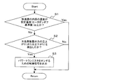
- the temperature control unit 70 is designed so that the operation of the temperature control unit 70 follows the flow shown in FIG. An example of the operation of the temperature control unit 70 will be described using the flow shown in FIG. First, the temperature control unit 70 determines whether or not the temperature inside the thermostatic chamber 20 is equal to or higher than a set temperature (heater on / off reference value) (step S1).
- Step S2 when it is determined that the temperature inside the constant temperature bath 20 is equal to or higher than the set temperature (Yes route of step S1), the process proceeds to step S1 again. On the other hand, if it is determined that the temperature inside the thermostat 20 is lower than the set temperature (No route of step S1), it is then determined whether the rising or falling of the inverted output of the crystal oscillator 30 is detected. (Step S2).
- step S3 when the rise or fall of the inverted output of the crystal oscillator 30 cannot be detected (No route of step S2), the process proceeds to step S1 again.
- a control signal for turning on the switching element is output (step S3).
- the delay unit 80 can also be realized by a CPU, FPGA, or the like, similar to the temperature control unit 70. Even when both or one of the temperature control unit 70 and the delay unit 80 is realized by a CPU, FPGA, or the like, the heater 40 causes the fall (or rise) of the inverted output C of the crystal oscillator 30 as in the timing chart of FIG. ) At the timing of the falling (or rising) of the inverted output C of the crystal oscillator 30.
- the power transistor by causing the power transistor to perform a switching operation as the switching element 60, it is possible to apply strong derating, and the reliability can be further improved. Further, since strong derating can be applied, a small element or an inexpensive element can be used for the switching element 60.
- the timing when the heater 40 is turned on and when the heater 40 is turned off coincident with the rise or fall of the output of the crystal oscillator 30, it is possible to suppress the generation of noise when the heater 40 is turned on and off. Since the generation of jitter and the like in the oscillation output can be suppressed, it is possible to further contribute to the improvement of high reliability. Further, since the generation of noise when the heater 40 is turned on and off can be suppressed, it is not necessary to arrange a capacitor having a large capacity in parallel with the heater 40, and the apparatus can be downsized.
- the set temperature detection circuit 71 outputs a control signal corresponding to the output of the temperature detection element 50, temperature control can be performed without providing hysteresis for the on / off temperature.
- the inside of the thermostatic chamber 20 with the crystal oscillator 30 is usually kept at 80 to 90 ° C., for example.
- the lifetime L of the semiconductor element can be obtained by the following equation (1).
- Equation (1) becomes It can be expressed.
- L25 is expressed by the following equation (3) by using the Arrhenius law.
- L90 is expressed by the following equation (4).
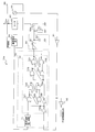
- FIG. 5 is a diagram illustrating an example of the configuration of the temperature control device 10a of the thermostatic chamber with a crystal oscillator according to the first modification.
- the temperature control device 10a of the thermostatic chamber with a crystal oscillator shown in FIG. 5 exemplarily shows the thermostatic chamber 20, the crystal oscillator 30, the heater 40, the temperature detecting element 50, and the thermostatic chamber 20 arranged inside the thermostatic chamber 20.
- each component having the above-described reference numeral has the same function as each component described above, and thus detailed description thereof is omitted.
- the switching element 60a controls on / off of the heater 40 by switching.
- a MOSFET is used as an example. Therefore, the drain of the MOSFET is connected to the heater 40, the source is grounded, and the control signal output from the delay unit 80 is input to the gate as an applied voltage. That is, the switching element 60a functions as an example of a switching element that performs on / off control of the heater.
- the temperature control unit 70 and the delay unit 80 can be realized by a CPU, FPGA, or the like.
- the temperature control devices 10 and 10a of the thermostatic chamber with a crystal oscillator shown in FIGS. 2 and 5 described above can be applied to, for example, a wireless transmission device.
- FIG. 6 is a diagram illustrating a configuration example applied to a wireless transmission device. 6 is illustratively a modulation / coding unit 101, a D / A conversion unit 102, a frequency conversion unit 103, a transmission antenna 104, and a temperature control device for a thermostatic chamber with a crystal oscillator. 10 or 10a.
- each component having the above-described reference numeral has the same function as each component described above, and a detailed description thereof will be omitted.
- Modulation / encoding section 101 performs predetermined modulation processing and encoding processing on transmission data, and outputs the result to D / A conversion section 102.
- the D / A conversion unit 102 converts the digital signal output from the modulation / coding unit 101 into an analog signal.
- the D / A conversion unit 102 appropriately divides and multiplies the crystal oscillator output of the temperature control device 10 (10a) of the thermostatic chamber with a crystal oscillator when performing conversion processing into an analog signal, and uses it as a clock.
- the frequency conversion unit 103 up-converts the analog signal output from the D / A conversion unit to a radio frequency. In the up-conversion, the frequency conversion unit 103 appropriately divides and multiplies the crystal oscillator output of the temperature control device 10 (10a) of the thermostatic chamber with a crystal oscillator and uses it as a local oscillation frequency.
- the transmission antenna 104 transmits the signal output from the frequency conversion unit 103.
- the modulation / coding unit 101, the D / A conversion unit 102, the frequency conversion unit 103, and the transmission antenna 104 are operated by the oscillation signal from the crystal oscillator 30 in the temperature control device 10 or 10a of the thermostat with crystal oscillator. It functions as an example of a unit. According to the above configuration, the wireless transmission device 100 can stably perform transmission processing without being affected by the environmental temperature.
- the power consumption of the apparatus 10 (10a) can be significantly reduced as compared with the conventional example, and thus the power consumption of the transmission apparatus 100 to which the apparatus 10 (10a) is applied can be greatly reduced. Furthermore, since this apparatus 10 (10a) can improve reliability more than a prior art example, the transmission apparatus 100 which applied this can also improve reliability.
- the transmission device 100 to which the device 10 (10a) is applied can be manufactured at a low cost and in a small size. 100 degrees of design freedom can be improved. Furthermore, since the device 10 (10a) can suppress noise when the heater is turned on and off, the transmission device 100 to which the device 10 (10a) is applied can obtain a stable output.
- FIG. 7 is a diagram illustrating a configuration example applied to a wireless reception device. 7 exemplarily includes a receiving antenna 201, a frequency conversion unit 102, an A / D conversion unit 203, a demodulation / decoding unit 204, and a temperature control device 10 for a thermostatic chamber with a crystal oscillator. Alternatively, 10a is provided.
- the frequency converter 202 down-converts the radio signal received by the receiving antenna 201 from a radio frequency to an intermediate frequency.
- the frequency conversion unit 202 appropriately divides and multiplies the crystal oscillator output of the temperature control device 10 (10a) of the above-described thermostatic chamber with crystal oscillator at the time of down-conversion, and uses it as a local oscillation frequency.
- the A / D conversion unit 203 performs sampling processing on the signal output from the frequency conversion unit 203 and converts the signal into a digital signal.
- the A / D conversion unit 203 appropriately divides and multiplies the crystal oscillator output of the temperature control device 10 (10a) of the above-described thermostatic chamber with crystal oscillator and uses it as a clock.
- the demodulation / decoding unit 204 extracts the transmitted data by performing demodulation processing and decoding processing on the digital signal output from the A / D conversion unit 203. That is, the reception antenna 201, the frequency conversion unit 102, the A / D conversion unit 203, and the demodulation / decoding unit 204 are operated by an oscillation signal from the crystal oscillator 30 in the temperature control device 10 or 10a of the thermostatic chamber with a crystal oscillator. Functions as an example.
- the wireless reception device 200 can stably perform reception processing without being affected by the environmental temperature. Further, as described above, the power consumption of the apparatus 10 (10a) can be greatly reduced as compared with the conventional example, and thus the power consumption of the receiving apparatus 200 to which the apparatus 10 (10a) is applied can be greatly reduced.
- this apparatus 10 (10a) can improve reliability more than a prior art example, the receiving apparatus 200 to which this apparatus 10 is applied can also improve reliability.
- the device 10 (10a) can use a small element or an inexpensive element as a switching element, the receiving device 200 to which the device 10 (10a) is applied can be manufactured at a low cost and in a small size. The degree of freedom in designing 200 can be improved.
- the present apparatus 10 (10a) can suppress noise when the heater is turned on / off, the receiving apparatus 200 to which this is applied can obtain a stable output.
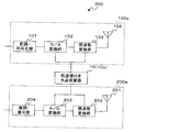
- the wireless transmission / reception device 300 may be configured by sharing the temperature control device 10 or 10a of the thermostat with crystal oscillator between the wireless transmission device 100a and the wireless reception device 200a.
- the detailed description is abbreviate
- the same effects as those of the first application example and the second application example described above can be obtained. Further, if the device 10 (10a) is shared by the wireless transmission device 100a and the wireless reception device 200a, the configuration can be further simplified. [6] Others The configurations and functions of the temperature control devices 10 and 10a of the above-described thermostatic chamber with crystal oscillator, the wireless transmission device 100, the wireless reception device 200, and the wireless transmission / reception device 300 are selected as necessary. It may be used in combination as appropriate. In other words, the above-described configurations and functions may be selected or used in appropriate combination so that the functions of the present invention can be exhibited.
- the base station in the wireless communication system is appropriately used by using the respective configurations and functions of the temperature control devices 10 and 10a of the thermostatic chamber with the crystal oscillator, the wireless transmission device 100, the wireless reception device 200, and the wireless transmission / reception device 300 as appropriate. Can be configured. Furthermore, in the above-described embodiment, the example in which the output of the crystal oscillator 30 is inverted and input to the temperature control unit 70 has been described, but an output that is not inverted can also be input to the temperature control unit 70.
- the output of the crystal oscillator 30 may be appropriately divided and multiplied before being input to the temperature control unit 70.
Landscapes
- Oscillators With Electromechanical Resonators (AREA)
Abstract
La présente invention porte sur : un réservoir thermostatique (20) dans lequel se trouve un oscillateur à cristal (30) émettant un signal d'oscillation ; un dispositif de chauffage (40) qui chauffe l'intérieur du réservoir thermostatique (20) ; une unité de détection de la température (50) qui détecte la température à l'intérieur du réservoir thermostatique (20) ; un élément de commutation (60) qui assure la commande marche/arrêt du dispositif de chauffage (40) ; et une unité de commande de la température (70) qui reçoit les résultats de la détection provenant de l'unité de détection de la température (50) et le signal d'oscillation provenant de l'oscillateur à cristal (30), effectue la synchronisation avec le signal d'oscillation, et assure la commande marche/arrêt de l'élément de commutation.
Priority Applications (2)
| Application Number | Priority Date | Filing Date | Title |
|---|---|---|---|
| PCT/JP2011/061323 WO2012157077A1 (fr) | 2011-05-17 | 2011-05-17 | Dispositif de commande de la température d'un réservoir thermostatique muni d'un oscillateur à cristal, dispositif d'émission sans fil, dispositif de réception sans fil, dispositif d'émission et de réception sans fil et station de base sans fil |
| JP2013514914A JP5610071B2 (ja) | 2011-05-17 | 2011-05-17 | 水晶発振器付き恒温槽の温度制御装置、無線送信装置、無線受信装置、無線送受信装置及び無線基地局 |
Applications Claiming Priority (1)
| Application Number | Priority Date | Filing Date | Title |
|---|---|---|---|
| PCT/JP2011/061323 WO2012157077A1 (fr) | 2011-05-17 | 2011-05-17 | Dispositif de commande de la température d'un réservoir thermostatique muni d'un oscillateur à cristal, dispositif d'émission sans fil, dispositif de réception sans fil, dispositif d'émission et de réception sans fil et station de base sans fil |
Publications (1)
| Publication Number | Publication Date |
|---|---|
| WO2012157077A1 true WO2012157077A1 (fr) | 2012-11-22 |
Family
ID=47176444
Family Applications (1)
| Application Number | Title | Priority Date | Filing Date |
|---|---|---|---|
| PCT/JP2011/061323 Ceased WO2012157077A1 (fr) | 2011-05-17 | 2011-05-17 | Dispositif de commande de la température d'un réservoir thermostatique muni d'un oscillateur à cristal, dispositif d'émission sans fil, dispositif de réception sans fil, dispositif d'émission et de réception sans fil et station de base sans fil |
Country Status (2)
| Country | Link |
|---|---|
| JP (1) | JP5610071B2 (fr) |
| WO (1) | WO2012157077A1 (fr) |
Cited By (2)
| Publication number | Priority date | Publication date | Assignee | Title |
|---|---|---|---|---|
| JP2021044114A (ja) * | 2019-09-10 | 2021-03-18 | スリーエイ ロジックス カンパニー リミテッド3A LOGICS Co.,LTD. | Cmosオシレーターから出力されたrf信号を熱エネルギーに転換する温度制御装置と加熱システム |
| US11038460B2 (en) | 2019-09-18 | 2021-06-15 | Seiko Epson Corporation | Circuit apparatus, oscillator, electronic instrument, and vehicle |
Families Citing this family (1)
| Publication number | Priority date | Publication date | Assignee | Title |
|---|---|---|---|---|
| JP3460526B2 (ja) | 1997-09-02 | 2003-10-27 | タカタ株式会社 | エアベルト装置 |
Citations (3)
| Publication number | Priority date | Publication date | Assignee | Title |
|---|---|---|---|---|
| JPH052434U (ja) * | 1991-02-15 | 1993-01-14 | 三菱電機株式会社 | 弾性表面波発振器 |
| JP2007273420A (ja) * | 2006-03-31 | 2007-10-18 | Nippon Dempa Kogyo Co Ltd | 温度制御装置 |
| JP2010062868A (ja) * | 2008-09-03 | 2010-03-18 | Fujitsu General Ltd | 電子機器 |
-
2011
- 2011-05-17 WO PCT/JP2011/061323 patent/WO2012157077A1/fr not_active Ceased
- 2011-05-17 JP JP2013514914A patent/JP5610071B2/ja not_active Expired - Fee Related
Patent Citations (3)
| Publication number | Priority date | Publication date | Assignee | Title |
|---|---|---|---|---|
| JPH052434U (ja) * | 1991-02-15 | 1993-01-14 | 三菱電機株式会社 | 弾性表面波発振器 |
| JP2007273420A (ja) * | 2006-03-31 | 2007-10-18 | Nippon Dempa Kogyo Co Ltd | 温度制御装置 |
| JP2010062868A (ja) * | 2008-09-03 | 2010-03-18 | Fujitsu General Ltd | 電子機器 |
Cited By (2)
| Publication number | Priority date | Publication date | Assignee | Title |
|---|---|---|---|---|
| JP2021044114A (ja) * | 2019-09-10 | 2021-03-18 | スリーエイ ロジックス カンパニー リミテッド3A LOGICS Co.,LTD. | Cmosオシレーターから出力されたrf信号を熱エネルギーに転換する温度制御装置と加熱システム |
| US11038460B2 (en) | 2019-09-18 | 2021-06-15 | Seiko Epson Corporation | Circuit apparatus, oscillator, electronic instrument, and vehicle |
Also Published As
| Publication number | Publication date |
|---|---|
| JP5610071B2 (ja) | 2014-10-22 |
| JPWO2012157077A1 (ja) | 2014-07-31 |
Similar Documents
| Publication | Publication Date | Title |
|---|---|---|
| Kundu et al. | A fully integrated digital LDO with built-in adaptive sampling and active voltage positioning using a beat-frequency quantizer | |
| JP7521885B2 (ja) | 電流ミラーを含むデジタル制御オシレータ | |
| CN106796438B (zh) | 电压到电流转换器 | |
| US8531234B2 (en) | Temperature detection device | |
| Li et al. | All-digital PLL for Bluetooth low energy using 32.768-kHz reference clock and≤ 0.45-V supply | |
| JP5610071B2 (ja) | 水晶発振器付き恒温槽の温度制御装置、無線送信装置、無線受信装置、無線送受信装置及び無線基地局 | |
| JP5377438B2 (ja) | センサのモニタリング装置 | |
| US8040160B2 (en) | Driver arrangement and signal generation method | |
| Shepherd et al. | 500 kHz–5 MHz phase-locked loops in high-temperature silicon carbide CMOS | |
| US10763830B2 (en) | Current controlled oscillator | |
| CN102237861A (zh) | 时钟占空比校正电路 | |
| JP4745102B2 (ja) | 基準電流制御回路、温度補償機能付き水晶発振器制御ic、水晶発振器および携帯電話機 | |
| US8525598B2 (en) | Digital to analog converter for phase locked loop | |
| JP2015119307A (ja) | 弛張発振器 | |
| Talegaonkar et al. | An 8 Gb/s–64 Mb/s, 2.3–4.2 mW/Gb/s burst-mode transmitter in 90 nm CMOS | |
| US9742413B2 (en) | Electronic device and information processing apparatus | |
| JP4634182B2 (ja) | 並行パスのサンプリングを用いたアナログ・エラーの判定 | |
| US10892769B2 (en) | Analog-to-digital converter with hysteresis | |
| US7411464B1 (en) | Systems and methods for mitigating phase jitter in a periodic signal | |
| JP6286962B2 (ja) | 出力信号発生装置 | |
| CN104516376A (zh) | 温度控制电路及带恒温槽的晶体振荡器 | |
| JP2009302224A (ja) | 半導体集積回路、温度変化検出方法 | |
| US20150244377A1 (en) | Compensated oscillator | |
| US20160187912A1 (en) | Current generator and method | |
| CN104685787B (zh) | 用于在高温下操作低功率电路的系统及方法 |
Legal Events
| Date | Code | Title | Description |
|---|---|---|---|
| 121 | Ep: the epo has been informed by wipo that ep was designated in this application |
Ref document number: 11865503 Country of ref document: EP Kind code of ref document: A1 |
|
| ENP | Entry into the national phase |
Ref document number: 2013514914 Country of ref document: JP Kind code of ref document: A |
|
| NENP | Non-entry into the national phase |
Ref country code: DE |
|
| 122 | Ep: pct application non-entry in european phase |
Ref document number: 11865503 Country of ref document: EP Kind code of ref document: A1 |