WO2012157104A1 - Dispositif d'éclairage - Google Patents
Dispositif d'éclairage Download PDFInfo
- Publication number
- WO2012157104A1 WO2012157104A1 PCT/JP2011/061482 JP2011061482W WO2012157104A1 WO 2012157104 A1 WO2012157104 A1 WO 2012157104A1 JP 2011061482 W JP2011061482 W JP 2011061482W WO 2012157104 A1 WO2012157104 A1 WO 2012157104A1
- Authority
- WO
- WIPO (PCT)
- Prior art keywords
- panel
- light source
- surface light
- panel support
- source panel
- Prior art date
- Legal status (The legal status is an assumption and is not a legal conclusion. Google has not performed a legal analysis and makes no representation as to the accuracy of the status listed.)
- Ceased
Links
Images


Classifications
-
- F—MECHANICAL ENGINEERING; LIGHTING; HEATING; WEAPONS; BLASTING
- F21—LIGHTING
- F21S—NON-PORTABLE LIGHTING DEVICES; SYSTEMS THEREOF; VEHICLE LIGHTING DEVICES SPECIALLY ADAPTED FOR VEHICLE EXTERIORS
- F21S8/00—Lighting devices intended for fixed installation
- F21S8/02—Lighting devices intended for fixed installation of recess-mounted type, e.g. downlighters
-
- F—MECHANICAL ENGINEERING; LIGHTING; HEATING; WEAPONS; BLASTING
- F21—LIGHTING
- F21V—FUNCTIONAL FEATURES OR DETAILS OF LIGHTING DEVICES OR SYSTEMS THEREOF; STRUCTURAL COMBINATIONS OF LIGHTING DEVICES WITH OTHER ARTICLES, NOT OTHERWISE PROVIDED FOR
- F21V19/00—Fastening of light sources or lamp holders
- F21V19/04—Fastening of light sources or lamp holders with provision for changing light source, e.g. turret
-
- F—MECHANICAL ENGINEERING; LIGHTING; HEATING; WEAPONS; BLASTING
- F21—LIGHTING
- F21V—FUNCTIONAL FEATURES OR DETAILS OF LIGHTING DEVICES OR SYSTEMS THEREOF; STRUCTURAL COMBINATIONS OF LIGHTING DEVICES WITH OTHER ARTICLES, NOT OTHERWISE PROVIDED FOR
- F21V17/00—Fastening of component parts of lighting devices, e.g. shades, globes, refractors, reflectors, filters, screens, grids or protective cages
- F21V17/10—Fastening of component parts of lighting devices, e.g. shades, globes, refractors, reflectors, filters, screens, grids or protective cages characterised by specific fastening means or way of fastening
- F21V17/107—Fastening of component parts of lighting devices, e.g. shades, globes, refractors, reflectors, filters, screens, grids or protective cages characterised by specific fastening means or way of fastening using hinge joints
-
- F—MECHANICAL ENGINEERING; LIGHTING; HEATING; WEAPONS; BLASTING
- F21—LIGHTING
- F21V—FUNCTIONAL FEATURES OR DETAILS OF LIGHTING DEVICES OR SYSTEMS THEREOF; STRUCTURAL COMBINATIONS OF LIGHTING DEVICES WITH OTHER ARTICLES, NOT OTHERWISE PROVIDED FOR
- F21V23/00—Arrangement of electric circuit elements in or on lighting devices
- F21V23/003—Arrangement of electric circuit elements in or on lighting devices the elements being electronics drivers or controllers for operating the light source, e.g. for a LED array
- F21V23/007—Arrangement of electric circuit elements in or on lighting devices the elements being electronics drivers or controllers for operating the light source, e.g. for a LED array enclosed in a casing
- F21V23/009—Arrangement of electric circuit elements in or on lighting devices the elements being electronics drivers or controllers for operating the light source, e.g. for a LED array enclosed in a casing the casing being inside the housing of the lighting device
-
- F—MECHANICAL ENGINEERING; LIGHTING; HEATING; WEAPONS; BLASTING
- F21—LIGHTING
- F21Y—INDEXING SCHEME ASSOCIATED WITH SUBCLASSES F21K, F21L, F21S and F21V, RELATING TO THE FORM OR THE KIND OF THE LIGHT SOURCES OR OF THE COLOUR OF THE LIGHT EMITTED
- F21Y2105/00—Planar light sources
-
- F—MECHANICAL ENGINEERING; LIGHTING; HEATING; WEAPONS; BLASTING
- F21—LIGHTING
- F21Y—INDEXING SCHEME ASSOCIATED WITH SUBCLASSES F21K, F21L, F21S and F21V, RELATING TO THE FORM OR THE KIND OF THE LIGHT SOURCES OR OF THE COLOUR OF THE LIGHT EMITTED
- F21Y2115/00—Light-generating elements of semiconductor light sources
- F21Y2115/20—Electroluminescent [EL] light sources
Definitions
- the present invention relates to an illumination device using a surface light source panel.
- a surface light source panel is widely used as a plate-like back illumination means used in a flat display device such as a liquid crystal display device, that is, a backlight light source.
- the backlight light source includes a row of a plurality of LEDs (light emitting diodes) or CCFL (cold cathode fluorescent lamp), a transparent rectangular light guide plate or diffusion plate that propagates light emitted from the linear light source in a planar shape, and , And planar light emission.
- An LED surface light emitting panel that emits light in a substantially planar shape in which a plurality of LEDs are arranged in a matrix on a plane is also known as a surface light source panel.
- organic EL panels and inorganic EL panels which are self-luminous planar light emitting elements in the form of films or plates using organic EL elements or inorganic EL elements using electroluminescence (hereinafter referred to as EL), are also attracting attention as surface light source panels.
- EL organic EL panels and inorganic EL panels, which are self-luminous planar light emitting elements in the form of films or plates using organic EL elements or inorganic EL elements using electroluminescence
- Patent Document 1 proposes a light-emitting panel type luminaire that uses snap coupling in order to improve workability of replacing a light-emitting panel.
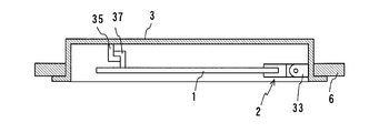
- the light-emitting panel type lighting fixture includes a light-emitting panel 1, a holding member 2 that holds the light-emitting panel 1, and a housing 3 that covers and accommodates the back side, and is embedded in a ceiling 6. Arranged.
- the engaging portion 17 and the engaged portion 35 provided on one edge of the light emitting panel 1 and the opposite edge of the light emitting panel 1 so as to emit light downward from the main surface of the light emitting panel 1.
- the light emitting panel 1 is held horizontally by the holding member 2 and the swing support portion 33 that sandwich the portion.
- the swing support portion 33 is provided to support the holding member 2 sandwiching the light emitting panel 1 so as to be swingable vertically as shown in FIG. 2 from the horizontal (FIG. 1). It is connected to 33 by a swing shaft to form a hinge.
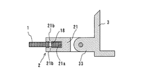
- the front surface of the holding member 2 is provided with a concave groove 21a extending over its entire width and recessed backward.
- the groove width of the groove 21a is set to be slightly larger than the thickness of the light emitting panel 1, and the edge of one side of the light emitting panel 1 can be inserted into the groove 21a.
- the main-body part 21 can be elastically deformed in the direction which the groove width of the ditch
- a hemispherical projection 21b that can be fitted into the fitting hole 18 is provided on each side surface of the concave groove 21a sandwiching the light emitting panel 1 at a position corresponding to the fitting hole 18 of the light emitting panel 1.
- the protrusion 21b is pushed by the light emitting panel 1 and elastically deforms so that the main body 21 spreads outward, and the fitting hole 18 is in a position that matches the protrusion 21b.
- the projection 21b is fitted into the fitting hole 18 by the restoring force of the main body 21, whereby the light emitting panel 1 and the holding member 2 are engaged (snap-coupled), and the light emitting panel 1 becomes the holding member 2. Retained.
- the light emitting panel 1 snap-coupled to the holding member 2 is pulled downward from the concave groove 21a while being swung downward by the swing support portion 33.
- the light emitting panel 1 can be removed, and conversely, the light emitting panel 1 can be snap-coupled to the holding member 2 if one side of the light emitting panel 1 is pushed into the concave groove 21a and pushed up.
- planar light sources such as planar light source panels.
- Patent Document 1 it is necessary to accurately insert the edge of the light-emitting panel as a thin surface light source into the thin concave groove 21a of the holding member.
- workability is significantly deteriorated.
- large light-emitting panel itself is heavy, there is a problem that it is difficult to sufficiently hold the panel by snap coupling.
- the strength of the panel is not sufficient, so that the panel itself can not withstand the force of inserting one side of the light-emitting panel into the holding member and bends. Further, when the light emitting panel is held at one end and leveled, there is a problem that the light emitting panel is bent without supporting its own weight.
- an example of a problem is to provide an illuminating device that can hold the surface light source panel reliably without causing the surface light source panel to bend with high workability for attaching and detaching the surface light source panel.
- An illuminating device is an illuminating device including a surface light source panel, and is provided with a housing having an opening and an outer edge that is disposed in the opening of the housing and is larger than the surface light source panel and on the housing side.
- a panel support that holds the panel; and a hinge that rotatably supports the panel support relative to the housing and that allows the panel support to be opened and closed.
- the illumination device according to the present invention is characterized in that the panel support or the surface light source panel has a temporary fixing portion of a convex portion that hooks and stops the surface light source panel when the panel support is opened.
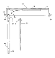
- FIG. 5 is a schematic sectional view taken along line AA in FIG. 4.
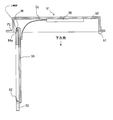
- FIG. 5 is a schematic sectional drawing which shows the illuminating device of embodiment by this invention which shows the state which opened the panel support body.
- FIG. 5 is a schematic front view which shows the example of the panel support body of the illuminating device of embodiment by this invention.
- FIG. 1 It is a schematic rear view which shows the panel support body of the illuminating device of embodiment by this invention. It is a schematic rear view which shows the surface light source panel of the illuminating device of embodiment by this invention. It is a schematic sectional drawing which shows the illuminating device of embodiment by this invention which shows the state which opened the panel support body. It is a general
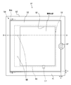
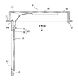
- FIG. 4 is a front view showing the lighting device 51 of this embodiment attached to a ceiling (not shown).
- FIG. 5 is a cross-sectional view taken along line AA in FIG.
- FIG. 5 shows a state when the lighting device 51 is normally used
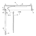
- FIG. 6 shows a state where the panel support 53 is opened when the surface light source panel 55 is replaced.
- the downward direction of the illumination device 51 is the light extraction direction.
- the illuminating device 51 demonstrates as what is installed in a ceiling, you may install not only in what is arrange
- the downward direction is referred to as the gravitational direction (vertical downward)
- the upward direction is referred to as the direction opposite to the gravitational direction (vertical upward).
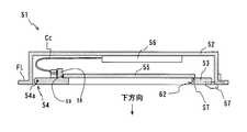
- the illumination device 51 includes a housing 52, a panel support 53, a hinge portion 54, a surface light source panel 55, a drive circuit 56, and a fastener 57.
- a temporary fixing pin 58 is provided so as to protrude from the panel support 53 to the back side, and passes through a through hole (pin insertion port 59) provided in the surface light source panel 55.
- the columnar body of the temporary fixing pin 58 and the pin insertion port 59 are formed so that there is a gap in the temporary insertion pin 58 so that the temporary fixing pin 58 is inserted into the pin insertion port 59 to constitute a temporary fixing structure.
- the surface light source panel 55 is electrically connected to the drive circuit 56 by a cable connector Cc.
- the housing 52 stores a panel support 53, a hinge portion 54, a surface light source panel 55, a drive circuit 56, and the like.
- a flange FL is provided around the opening 52a of the casing 52 so as to be an attachment portion to the ceiling, and the panel support 53 is disposed in the opening 52a with a gap G so as to be substantially flush with the flange FL.
- the panel support 53 is supported by the hinge portion 54 and the fastener 57 so that the side on which the surface light source panel 55 is fixed faces the inside of the housing 52.
- the panel support 53 is a member for fixing the surface light source panel 55, has a mounting portion ST that supports at least the periphery of the surface light source panel 55, and has a frame shape having an outer edge larger than the surface light source panel 55 or It is a plate-shaped rigid body. As shown in FIG. 5, the upper surface of the panel support 53 is configured to hold the lower surface of the surface light source panel 55. However, when the illumination opening 62 of the panel support 53 is a through hole, the surface light source panel 55 is supported only at the periphery thereof, but is not held at least at one point or only one side. . Since the panel support 53 has an outer edge larger than the surface light source panel 55, the surface light source panel 55 is held at a plurality of points or a plurality of edges of the annular mounting portion ST.
- the surface light source panel 55 is horizontally fixed to the housing 52 as shown in FIG. 5 together with the panel support 53.
- the material of the panel support 53 is not particularly limited as long as the material has sufficient strength, and may be a metal, an alloy, a resin, a plastic, wood, or the like.
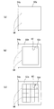
- An example of the light extraction structure of the panel support 53 is as follows.
- the panel support 53 may be a frame in which a through-hole-shaped illumination opening 62 is provided in a portion where the surface light emitting portion of the surface light source panel 55 is located. Light emission from the surface light source panel 55 is taken out through the illumination opening 62.
- the entire panel support 53a may be a plate formed of a light-transmitting material such as glass, a transparent resin such as acrylic, or transparent plastics. Light emission from the surface light source panel 55 is extracted through the panel support 53a.
- a panel support is provided as a plate body in which a translucent plate 53c made of a translucent material such as glass or acrylic resin is fitted and arranged in the illumination opening 62 of the panel support frame 53b. It may be a body light extraction structure. Light emission from the surface light source panel 55 is extracted through the translucent plate 53c.
- the panel support light extraction structure may be a plate body in which a grid made of metal, resin, or the like is arranged in the illumination opening 62 of the panel support frame 53b. Light emission from the surface light source panel 55 is taken out through the illumination opening 62.
- the panel support may be provided with an optical member (not shown) such as an optical film or a phosphor for the purpose of light emission diffusion and color matching of the surface light source panel.
- the front side of the panel support 53 also serves as a decorative panel.
- the hinge portion 54 is a mechanism that rotatably supports the panel support 53 with respect to the casing 52 and allows the panel support 53 to be opened and closed. Specifically, the hinge portion 54 is disposed between the housing 52 and one side of the outer peripheral edge of the panel support 53, and the panel support 53 can be rotated with respect to the housing 52. Is supported.
- the hinge part 54 is provided with a pipe part at a part of at least one end of the casing 52 and the panel support 53, and a shaft 54a is fitted to the pipe part, and each is coupled by the shaft 54a. The support 53 is rotated. Therefore, as shown in FIG.
- the panel support 53 pivotally supported by the housing 52 is rotatable downward about the shaft 54 a of the hinge portion 54.
- the hinge portion 54 is preferably rotatable so that the casing 52 and the panel support 53 spread to an angle of 45 degrees or more so that the surface light source panel 55 can be easily replaced.
- an organic EL panel which is a self-luminous planar light emitting element, is used in the lighting device, but an inorganic EL panel may be used instead.
- the surface light source panel may be a light-emitting plate that uses a light guide plate or a diffusion plate that propagates light emitted from a linear light source of LED or CCFL in a planar shape so that the emitted light can be extracted in a planar shape.
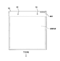
- FIG. 8 shows a state in which the panel support 53 is viewed from the back side when the panel support 53 is opened.
- FIG. 9 shows the surface light source panel 55 viewed from the back side.
- the panel support 53 is provided with temporary fixing pins 58 (temporary fixing portions).
- the surface light source panel 55 is provided with a pin insertion port 59 into which the temporary fixing pin 58 is inserted.
- the arrangement of the temporary fixing pin 58 and the pin insertion port 59 is set in advance so that the surface light source panel 55 is positioned so as to be aligned with the light extraction surface on the panel support 53.
- the two temporary fixing pins 58 of the convex portion are provided on the mounting portion ST surrounding the illumination opening portion 62 so as to be positioned on the horizontal line.
- the two pin insertion openings 59 are provided on the periphery of the surface light emitting portion of the surface light source panel 55 so that the surface light emitting portion of the surface light source panel 55 and the illumination opening 62 are aligned.
- the set of the temporary fixing pin 58 and the pin insertion port 59 is not limited to two, and may be one set or three or more sets.
- the surface light source panel 55 is fixed on the panel support 53 by the latch Lt of the support 53 provided on one side adjacent to the side on which the set of the temporary fixing pins 58 is provided.
- the fixing of the surface light source panel 55 is not limited to the latch, and a known fixing method such as screwing can be applied.
- the drive circuit 56 is connected to a power supply line such as the surface light source panel 55 via the conductive cable Cc, and is an electric circuit for supplying power to the surface light source panel 55.
- the driving circuit 56 may be configured so that at least two of the light emitting elements can be driven under different conditions.
- At least two power supply lines to the surface light source panel are required for organic EL panels and inorganic EL panels.
- three or more power supply lines are required.
- the fastener 57 is a member for fixing the panel support 53 to the housing 52.
- the fastener 57 is provided on the hinge portion facing side of the casing 52 in order to support one side of the outer peripheral edge of the panel support 53 facing the hinge portion 54.
- the structure and material of the fastener 57 are not particularly limited as long as the fastener 57 has sufficient strength to withstand the weight of the panel support 53 and the surface light source panel 55. It is desirable that the fastener 57 can be opened and closed with at least one hand.
- the fastener 57 and the panel support 53 need not be fixed to each other.
- the pin insertion port 59 of the new surface light source panel 55 is connected to the panel.
- the new surface light source panel 55 can be hung on the temporary fixing pin 58 by being inserted into the temporary fixing pin 58 of the support 53.
- the panel support 53 and the surface light source panel 55 are fixed by a latch (not shown).
- the conductive cable Cc from the drive circuit 56 is connected to the surface light source panel 55.
- the panel support 53 is only hung on the casing 52, so that it is not necessary to remove the panel support 53 and temporarily place it below.
- the hinge portion 54 may have a structure that allows the panel support 53 to be detached from the housing 52.
- FIG. 11 is a schematic partial cutaway perspective view showing a hinge portion between the casing 52 of the lighting device and the panel support 53, and shows a state in which a part of the casing 52 is cut off.
- a pair of grooves 52 b each having a bowl-shaped inner wall surface are formed on the opposing side walls of the casing 52 in a similar shape, and the panel support 53
- a pair of fixed shafts 54a is fitted into the groove 52b.
- the shaft 54a is pivotally supported by the flange 52c at the end of the bowl shape.
- the panel support 53 is removed from the casing 52 by moving the shaft 54a upward and moving it horizontally and downward. It becomes possible.
- a removable hinge portion 54 shown in FIG. 11B is formed by forming a pair of grooves 53b having bowl-shaped inner wall surfaces on opposite side walls of the panel support 53 in a similar shape (or through the grooves 53b). And a pair of shafts 54a fixed to the casing 52 may be fitted into the grooves 53b. In the configuration shown in FIG. 11B, the shaft 54a is normally pivotally supported by the flange 53c at the tip of the bowl. When removing the panel support 53, the panel support 53 is turned downward to be vertical, and then lifted and moved in the horizontal direction of the shaft 54a, so that the panel support 53 can be removed from the housing 52.
- the panel support 53 When the panel support 53 has a structure that can be removed by the hinge portion 54, the panel support 53 can be removed to work on a table or the like. As a result, the burden on the replacement work can be reduced. In particular, a surface light source panel that easily breaks and a surface light source panel that easily bends such as a film are particularly effective.
- the temporary fixing pin 58 of the convex portion and the pin insertion port 59 of the concave portion are respectively corresponding positions of the panel support 53 and a part of the surface light source panel 55 so as to be caught in the vertical direction.
- the temporary fixing pin and the pin insertion opening of the recess may be reversed. That is, as shown in FIG. 12, two temporary fixing pins 58 are provided in the vicinity of the upper edge of the surface light source panel 55 as temporary fixing portions, and the pin insertion port 59 of the concave portion is used as the panel support 53. You may form in the corresponding position.
- the two temporary fixing pins 58 of the convex portion are provided on the mounting portion surrounding the illumination opening 62 so as to be positioned on the horizontal line.
- the remaining one of the panel support 53 or the surface light source panel 55 having the temporary fixing pin 58 of the temporary fixing portion can have a concave portion that is hooked with the temporary fixing pin 58.
- two temporary fixing pins 58 are provided on the lower back side of the light extraction portion of the panel support 53, and one side of the lower end portion of the surface light source panel 55 is temporarily provided there. It can also be set as the structure which mounts and stands. According to this, even if the surface light source panel 55 has a certain degree of strength and is heavy, it can be hooked on the panel support 53.
- two convex temporary fixing pins 58 are provided on the upper outer edge of the surface light source panel 55, and the surface light source panel 55 is temporarily fixed on the upper outer edge of the panel support 53.
- a configuration in which the pin 58 is hooked is also possible.
- the temporary fixing pin 58 pin insertion port 59
- the temporary fixing pin 58 pin insertion port 59
- other configurations are the same. Therefore, the same configuration using the same reference numerals will be described. Is omitted, and different configurations are described. As described above, since one of the panel support 53 and the surface light source panel 55 has the temporary fixing portion 58 of the convex portion, the surface light source panel 55 can be hooked and stopped.
- the surface light source panel is temporarily fixed to the panel support by being hooked by a temporary fixing portion such as one temporary fixing pin of the panel support or the surface light source panel. Therefore, both hands of the operator are freed, and the subsequent workability is improved. Even if the surface light source panel is heavy, the frame of the panel support has a structure in which the edge supports at least the edge of the panel. Therefore, the large surface light source panel can be safely and securely held without causing bending.
- the surface light source panel is fixed so as to be in close contact with the entire frame of the panel support, so that even a surface light source panel with low strength can be reliably bent without bending.
- a surface light source panel can be held.
Landscapes
- Engineering & Computer Science (AREA)
- General Engineering & Computer Science (AREA)
- Fastening Of Light Sources Or Lamp Holders (AREA)
- Securing Globes, Refractors, Reflectors Or The Like (AREA)
Abstract
L'invention vise à procurer un dispositif d'éclairage qui est apte à maintenir fermement un panneau de source de lumière de surface sans voiler le panneau de source de lumière de surface, ce par quoi l'aptitude au travail d'installation et de retrait du panneau de source de lumière de surface est élevée. A cet effet, l'invention porte sur un dispositif d'éclairage, qui comprend : un corps de support de panneau qui est positionné dans l'ouverture d'un boîtier, qui a un bord externe qui est plus grand qu'un panneau de source de lumière de surface, et qui supporte le panneau de source de lumière de surface sur le côté boîtier ; et une charnière qui supporte le corps de support de panneau de façon à pouvoir tourner par rapport au boîtier, et qui permet au corps de support de panneau de s'ouvrir et de se fermer. Le corps de support de panneau ou le panneau de source de lumière de surface comporte une partie d'arrêt temporaire avec une section saillante, qui s'accroche au panneau de source de lumière de surface et qui arrête celui-ci lorsque le corps de support de panneau est ouvert.
Priority Applications (2)
| Application Number | Priority Date | Filing Date | Title |
|---|---|---|---|
| PCT/JP2011/061482 WO2012157104A1 (fr) | 2011-05-19 | 2011-05-19 | Dispositif d'éclairage |
| JP2011544533A JPWO2012157104A1 (ja) | 2011-05-19 | 2011-05-19 | 照明装置 |
Applications Claiming Priority (1)
| Application Number | Priority Date | Filing Date | Title |
|---|---|---|---|
| PCT/JP2011/061482 WO2012157104A1 (fr) | 2011-05-19 | 2011-05-19 | Dispositif d'éclairage |
Publications (1)
| Publication Number | Publication Date |
|---|---|
| WO2012157104A1 true WO2012157104A1 (fr) | 2012-11-22 |
Family
ID=47176467
Family Applications (1)
| Application Number | Title | Priority Date | Filing Date |
|---|---|---|---|
| PCT/JP2011/061482 Ceased WO2012157104A1 (fr) | 2011-05-19 | 2011-05-19 | Dispositif d'éclairage |
Country Status (2)
| Country | Link |
|---|---|
| JP (1) | JPWO2012157104A1 (fr) |
| WO (1) | WO2012157104A1 (fr) |
Cited By (3)
| Publication number | Priority date | Publication date | Assignee | Title |
|---|---|---|---|---|
| WO2015098497A1 (fr) * | 2013-12-27 | 2015-07-02 | 株式会社カネカ | Structure de fixation pour des panneaux électroluminescents, structure d'agencement aligné pour des panneaux électroluminescents et panneau électroluminescent |
| JP2015138576A (ja) * | 2014-01-20 | 2015-07-30 | 株式会社カネカ | 発光パネル |
| US20230010234A1 (en) * | 2021-07-09 | 2023-01-12 | Eaton Intelligent Power Limited | Linear led luminaire housing for use in harsh and hazardous locations |
Citations (7)
| Publication number | Priority date | Publication date | Assignee | Title |
|---|---|---|---|---|
| JP2004140185A (ja) * | 2002-10-17 | 2004-05-13 | Matsushita Electric Ind Co Ltd | 発光装置 |
| JP2007005226A (ja) * | 2005-06-27 | 2007-01-11 | Matsushita Electric Works Ltd | 照明装置 |
| JP2007250303A (ja) * | 2006-03-15 | 2007-09-27 | Matsushita Electric Works Ltd | 発光パネル式照明器具 |
| JP2009158103A (ja) * | 2007-12-25 | 2009-07-16 | Panasonic Electric Works Co Ltd | El照明装置 |
| JP2009170249A (ja) * | 2008-01-16 | 2009-07-30 | Nec Lighting Ltd | 照明器具 |
| JP2010153314A (ja) * | 2008-12-26 | 2010-07-08 | Toshiba Lighting & Technology Corp | 照明器具 |
| JP2010157375A (ja) * | 2008-12-26 | 2010-07-15 | Toshiba Lighting & Technology Corp | 照明器具 |
Family Cites Families (7)
| Publication number | Priority date | Publication date | Assignee | Title |
|---|---|---|---|---|
| JPS58104422U (ja) * | 1982-01-08 | 1983-07-15 | 東芝テック株式会社 | 軸支持構造 |
| JPS60167521U (ja) * | 1984-04-17 | 1985-11-07 | ワイケイケイ株式会社 | 強化プラスチツク製スライドフアスナ−用スライダ− |
| JPH01232382A (ja) * | 1988-03-14 | 1989-09-18 | Hitachi Ltd | 液晶表示装置 |
| JP4041411B2 (ja) * | 2003-02-07 | 2008-01-30 | 松下電器産業株式会社 | カード型led光源用回動ソケット |
| JP4205710B2 (ja) * | 2005-09-27 | 2009-01-07 | Necディスプレイソリューションズ株式会社 | 筐体へのカバーの着脱構造 |
| KR200405808Y1 (ko) * | 2005-10-10 | 2006-01-11 | 홍순교 | 휴대용 전등 |
| JP2007250302A (ja) * | 2006-03-15 | 2007-09-27 | Matsushita Electric Works Ltd | 発光パネル式照明器具 |
-
2011
- 2011-05-19 WO PCT/JP2011/061482 patent/WO2012157104A1/fr not_active Ceased
- 2011-05-19 JP JP2011544533A patent/JPWO2012157104A1/ja active Pending
Patent Citations (7)
| Publication number | Priority date | Publication date | Assignee | Title |
|---|---|---|---|---|
| JP2004140185A (ja) * | 2002-10-17 | 2004-05-13 | Matsushita Electric Ind Co Ltd | 発光装置 |
| JP2007005226A (ja) * | 2005-06-27 | 2007-01-11 | Matsushita Electric Works Ltd | 照明装置 |
| JP2007250303A (ja) * | 2006-03-15 | 2007-09-27 | Matsushita Electric Works Ltd | 発光パネル式照明器具 |
| JP2009158103A (ja) * | 2007-12-25 | 2009-07-16 | Panasonic Electric Works Co Ltd | El照明装置 |
| JP2009170249A (ja) * | 2008-01-16 | 2009-07-30 | Nec Lighting Ltd | 照明器具 |
| JP2010153314A (ja) * | 2008-12-26 | 2010-07-08 | Toshiba Lighting & Technology Corp | 照明器具 |
| JP2010157375A (ja) * | 2008-12-26 | 2010-07-15 | Toshiba Lighting & Technology Corp | 照明器具 |
Cited By (5)
| Publication number | Priority date | Publication date | Assignee | Title |
|---|---|---|---|---|
| WO2015098497A1 (fr) * | 2013-12-27 | 2015-07-02 | 株式会社カネカ | Structure de fixation pour des panneaux électroluminescents, structure d'agencement aligné pour des panneaux électroluminescents et panneau électroluminescent |
| US9995470B2 (en) | 2013-12-27 | 2018-06-12 | Kaneka Corporation | Attachment structure for light-emitting panels, aligned-arrangement structure for light-emitting panels, and light-emitting panel |
| JP2015138576A (ja) * | 2014-01-20 | 2015-07-30 | 株式会社カネカ | 発光パネル |
| US20230010234A1 (en) * | 2021-07-09 | 2023-01-12 | Eaton Intelligent Power Limited | Linear led luminaire housing for use in harsh and hazardous locations |
| US12078306B2 (en) * | 2021-07-09 | 2024-09-03 | Eaton Intelligent Power Limited | Linear LED luminaire housing for use in harsh and hazardous locations |
Also Published As
| Publication number | Publication date |
|---|---|
| JPWO2012157104A1 (ja) | 2014-07-31 |
Similar Documents
| Publication | Publication Date | Title |
|---|---|---|
| JP5697492B2 (ja) | 照明器具 | |
| US9069106B1 (en) | Systems, methods, and devices for providing an edge-lit light emitting diode light panel | |
| CN101689337A (zh) | 无线控制发光显示系统 | |
| CN101641548A (zh) | 面板安装的发光元件组件 | |
| US20160356430A1 (en) | Snap in retrofit panel | |
| KR102174478B1 (ko) | 표시 장치 | |
| CN100474046C (zh) | 液晶显示设备 | |
| WO2012157104A1 (fr) | Dispositif d'éclairage | |
| US20130242556A1 (en) | Lighting apparatus | |
| JP5891400B2 (ja) | 照明器具 | |
| CN104249958A (zh) | 电梯的指示灯 | |
| JP5842132B2 (ja) | 照明器具 | |
| JP2012243757A (ja) | 照明装置 | |
| JP5665155B2 (ja) | 照明装置、バックライト及び液晶表示装置 | |
| JP2009162919A (ja) | 表示装置 | |
| JP4315103B2 (ja) | 棚板装置 | |
| JP2016143617A (ja) | 照明器具 | |
| JP6132873B2 (ja) | 照明装置 | |
| JP7311255B2 (ja) | Ledモジュールユニットを備えた照明装置 | |
| KR20110037727A (ko) | 액정 표시 장치 | |
| JP2015030605A (ja) | 乗客コンベアの欄干照明装置 | |
| KR20080094432A (ko) | 도광판에 의하여 발광 수단이 구비된 대형의 광고판 | |
| KR100540055B1 (ko) | 광원용 방열프레임이 구비된 백라이트 유니트 | |
| JP2019197659A (ja) | 面発光ユニット | |
| JP7464908B2 (ja) | 誘導灯 |
Legal Events
| Date | Code | Title | Description |
|---|---|---|---|
| ENP | Entry into the national phase |
Ref document number: 2011544533 Country of ref document: JP Kind code of ref document: A |
|
| 121 | Ep: the epo has been informed by wipo that ep was designated in this application |
Ref document number: 11865711 Country of ref document: EP Kind code of ref document: A1 |
|
| NENP | Non-entry into the national phase |
Ref country code: DE |
|
| 122 | Ep: pct application non-entry in european phase |
Ref document number: 11865711 Country of ref document: EP Kind code of ref document: A1 |