WO2012157142A1 - 妨害波信号除去装置、gnss受信装置、移動端末、妨害波信号除去プログラム、および妨害波信号除去方法 - Google Patents
妨害波信号除去装置、gnss受信装置、移動端末、妨害波信号除去プログラム、および妨害波信号除去方法 Download PDFInfo
- Publication number
- WO2012157142A1 WO2012157142A1 PCT/JP2011/079298 JP2011079298W WO2012157142A1 WO 2012157142 A1 WO2012157142 A1 WO 2012157142A1 JP 2011079298 W JP2011079298 W JP 2011079298W WO 2012157142 A1 WO2012157142 A1 WO 2012157142A1
- Authority
- WO
- WIPO (PCT)
- Prior art keywords
- signal
- interference wave
- frequency
- wave signal
- notch filter
- Prior art date
- Legal status (The legal status is an assumption and is not a legal conclusion. Google has not performed a legal analysis and makes no representation as to the accuracy of the status listed.)
- Ceased
Links
Images



Classifications
-
- G—PHYSICS
- G01—MEASURING; TESTING
- G01S—RADIO DIRECTION-FINDING; RADIO NAVIGATION; DETERMINING DISTANCE OR VELOCITY BY USE OF RADIO WAVES; LOCATING OR PRESENCE-DETECTING BY USE OF THE REFLECTION OR RERADIATION OF RADIO WAVES; ANALOGOUS ARRANGEMENTS USING OTHER WAVES
- G01S19/00—Satellite radio beacon positioning systems; Determining position, velocity or attitude using signals transmitted by such systems
- G01S19/01—Satellite radio beacon positioning systems transmitting time-stamped messages, e.g. GPS [Global Positioning System], GLONASS [Global Orbiting Navigation Satellite System] or GALILEO
- G01S19/13—Receivers
- G01S19/21—Interference related issues ; Issues related to cross-correlation, spoofing or other methods of denial of service
-
- H—ELECTRICITY
- H04—ELECTRIC COMMUNICATION TECHNIQUE
- H04B—TRANSMISSION
- H04B1/00—Details of transmission systems, not covered by a single one of groups H04B3/00 - H04B13/00; Details of transmission systems not characterised by the medium used for transmission
- H04B1/06—Receivers
- H04B1/10—Means associated with receiver for limiting or suppressing noise or interference
- H04B1/1027—Means associated with receiver for limiting or suppressing noise or interference assessing signal quality or detecting noise/interference for the received signal
- H04B1/1036—Means associated with receiver for limiting or suppressing noise or interference assessing signal quality or detecting noise/interference for the received signal with automatic suppression of narrow band noise or interference, e.g. by using tuneable notch filters
-
- H—ELECTRICITY
- H04—ELECTRIC COMMUNICATION TECHNIQUE
- H04B—TRANSMISSION
- H04B1/00—Details of transmission systems, not covered by a single one of groups H04B3/00 - H04B13/00; Details of transmission systems not characterised by the medium used for transmission
- H04B1/69—Spread spectrum techniques
- H04B1/707—Spread spectrum techniques using direct sequence modulation
- H04B1/7097—Interference-related aspects
- H04B1/71—Interference-related aspects the interference being narrowband interference
- H04B1/7101—Interference-related aspects the interference being narrowband interference with estimation filters
Definitions
- the present invention relates to an interfering wave signal removing apparatus that removes interfering waves that are different from signals to be received as a main object, and a GNSS receiving apparatus and a mobile terminal including the interfering wave signal removing apparatus.
- GNSS Global Navigation System
- GPS Global Positioning System
- GNSS signal broadcast from a positioning satellite is received and used for positioning.
- the GNSS signal is composed of a spread spectrum signal that is code-modulated with a pseudo-noise code.
- Patent Document 1 and Patent Document 2 describe an interference wave signal removal device that detects and removes a narrow (narrow band) interference wave signal having a frequency band different from that of the GNSS signal.
- FIG. 1 is a main circuit block diagram of a conventional interference wave signal removing apparatus 100P disclosed in Patent Document 1.
- FIG. 2 is a main circuit block diagram of a conventional interference wave signal removal device 110P shown in Patent Document 2.
- FIG. 1 is a main circuit block diagram of a conventional interference wave signal removing apparatus 100P disclosed in Patent Document 1.
- FIG. 2 is a main circuit block diagram of a conventional interference wave signal removal device 110P shown in Patent Document 2.
- FIG. 1 is a main circuit block diagram of a conventional interference wave signal removal device 110P shown in Patent Document 2.
- the interference wave signal removal device 100P described in Patent Literature 1 includes a control unit 101P, a notch filter 102P, a frequency analysis unit 103P, and a frequency scanning unit 104P.
- the control unit 101P specifies the frequency of the interference wave signal from the frequency spectrum of the input signal S i obtained from the frequency analysis unit 103P and the frequency spectrum of the output signal S op1 obtained from the frequency scanning unit 104P.
- the control unit 101P adjusts the attenuation characteristic of the notch filter 102P so as to attenuate the interference wave signal component from the information of the specified interference wave signal frequency.
- the interference wave signal removal device 110P described in Patent Literature 2 includes a control unit 111P, a notch filter 112P, and a frequency estimation unit 113P.
- the control unit 111P adjusts the attenuation characteristic of the notch filter 112P based on the interference wave signal frequency estimation information from the frequency estimation unit 113P.
- the frequency estimation unit 113P specifies the frequency of the interference wave signal from the frequency spectrum of the input signal S i and the output signal S op2 .
- the interference wave signal removal devices described in Patent Documents 1 and 2 detect the interference wave signal and estimate the frequency using both the signal input to the notch filter and the signal output from the notch filter. This increases the circuit scale, complicates the control algorithm, and further increases the control processing load of the control unit.
- the interference wave signal removal device described in Patent Document 2 detects the interference wave signal from the input signal and the interference wave signal from the output signal in a time-sharing manner, thereby detecting the occurrence or disappearance of the interference wave signal. It takes a long time to do.
- the frequency of the interference wave signal having a strong signal strength and the frequency of the interference wave signal having a low signal strength are close to each other, it is difficult to detect the interference wave signal having a low signal strength unless the frequency resolution is improved.
- the frequency resolution is improved, the circuit scale and the processing load increase accordingly.
- an object of the present invention is to provide an interference wave signal removal device that can reliably remove an interference wave signal with a simple structure.
- the interference wave signal removal device for removing an interference wave signal different from the desired signal in the present invention includes a notch filter, a frequency scanning unit, and a control unit.
- the notch filter has a configuration capable of adjusting the frequency of the attenuation pole.
- the frequency scanning unit scans the output signal of the notch filter with a predetermined bandwidth, and detects a frequency spectrum of the signal intensity.
- a control unit configured to set an attenuation pole frequency based on a frequency spectrum of the signal intensity detected by the frequency scanning unit and a signal output from the notch filter before the interference wave removal processing; Removal device.
- the control unit detects the frequency of the interfering wave signal from the frequency scanning result by the frequency scanning unit.
- the control unit sets the frequency of the interference signal to the attenuation pole frequency of the notch filter, and adjusts the frequency position of the attenuation pole of the notch filter.
- an input signal including an interfering wave signal is input to the notch filter having the attenuation pole frequency adjusted in this way, only the interfering wave signal is removed.
- the interference wave signal disappears, the frequency component of the interference wave signal does not exist in the signal before the interference wave removal processing by the notch filter.
- the control unit when the control unit detects that the frequency component of the interference wave signal does not exist in the signal before the interference wave removal process output from the notch filter, the control unit cancels the attenuation pole frequency of the notch filter. Accordingly, it is possible to set an appropriate notch filter in accordance with the state of the interference wave signal included in the input signal.
- a plurality of notch filters are provided and connected in series.
- the control unit sets the attenuation pole frequency of each notch filter based on the signal output from each notch filter before the interference wave removal process.
- a plurality of notch filters can be individually set for each jamming signal, so that even if a plurality of jamming signals are included in the input signal, each can be appropriately removed. Furthermore, since the disappearance can be determined for each interfering wave signal, an appropriate notch filter can be set according to the states of the plurality of interfering wave signals included in the input signal.
- the notch filter includes a down converter, a baseband signal generation unit, a subtraction element, and an up converter.
- the down converter multiplies the input signal by the attenuation pole setting signal output from the control unit.
- the baseband signal generation unit extracts a baseband component of the downconverted signal and generates a baseband signal.
- the subtracting element subtracts the baseband signal from the downconverted signal.
- the up-converter multiplies the subtracted signal by the attenuation pole setting signal.
- a notch filter outputs a baseband signal to a control part as a signal before an interference wave removal process.
- This configuration shows the specific configuration of the notch filter.
- the baseband component of the down-convert signal obtained by multiplying the input signal by the attenuation pole setting signal corresponds to the frequency component of the interference wave signal. Therefore, by outputting the baseband signal to the control unit, the control unit can accurately detect the continuation / disappearance of the interference wave signal. Further, this configuration does not require a circuit configuration only for extracting the frequency component of the interference wave signal from the input signal, so that the interference wave signal removal device can be realized with a simpler configuration. This configuration is more effective when there are a plurality of notch filters and the continuation and cancellation of a plurality of interference wave signals are individually monitored.
- the present invention also relates to a GNSS receiver that receives and demodulates a GNSS signal.
- the GNSS receiving device includes the above-described interference wave signal removing device, a receiving unit, an acquisition tracking unit, and a positioning calculation unit.
- the receiving unit is connected to the front stage of the interference wave signal removal device, receives a GNSS signal as a desired signal, generates a GNSS reception signal, and outputs the GNSS reception signal to the interference wave signal removal device.
- the acquisition tracking unit acquires and tracks the GNSS reception signal after the interference wave signal is removed.
- the positioning calculation unit performs positioning using the GNSS signal being tracked.
- the speed and accuracy of acquisition and tracking are improved, so that the convergence speed of the positioning calculation and the accuracy of the positioning result are improved.
- the present invention also relates to a mobile terminal, and the mobile terminal includes the above-described GNSS receiver and an application processing unit that executes a predetermined application using the positioning calculation result of the positioning calculation unit.
- the mobile terminal includes the above-described GNSS receiver and an application processing unit that executes a predetermined application using the positioning calculation result of the positioning calculation unit.
- the above-described GNSS receiver is provided, and the highly accurate positioning result can be used. Therefore, the performance of the application using the positioning result is improved.
- an interference wave removing device that reliably removes an interference wave can be realized with a simple configuration.
- FIG. 1 It is a main circuit block diagram of the conventional interference wave signal removal apparatus 100P shown in Patent Document 1. It is a main circuit block diagram of the conventional interference wave signal removal apparatus 110P shown in Patent Document 2. It is a block diagram of GNSS receiver 10 concerning a 1st embodiment. It is a block diagram of the interference wave signal removal part 50 which concerns on 1st Embodiment. 3 is a circuit block diagram of a notch filter 52 according to the first embodiment.
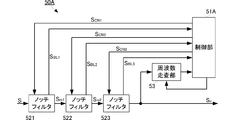
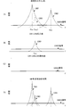
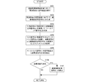
- FIG. It is a block diagram of an interference wave signal removal unit 50A having a multi-stage notch filter. It is processing explanatory drawing at the time of using the interference wave signal removal part 50A. It is a block diagram of interference wave signal removal part 50B concerning a 2nd embodiment. 5 is a flowchart illustrating a jamming signal removal method according to the present invention.
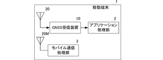
- FIG. 2 is a block diagram of main components of a mobile terminal 1 including a GNSS signal receiving apparatus 10.
- the interference wave signal removal apparatus according to the first embodiment of the present invention will be described with reference to the drawings.
- the interference wave signal removal device of the present embodiment functions as the interference wave signal removal unit 50 of the GNSS reception device 10.
- FIG. 3 is a block diagram of the GNSS receiver 10 according to the first embodiment.
- the GNSS receiver 10 includes a GNSS antenna 20, an RF front end unit 30, an analog-digital conversion unit (ADC) 40, an interference wave signal removal unit 50, an acquisition tracking unit 60, and a positioning calculation unit 70.
- the GNSS antenna 20 receives a radio signal including a GNSS signal and outputs the radio signal to the RF front end unit 30.
- the GNSS signal is a signal obtained by code-modulating a carrier wave signal with a pseudo spread code, and is a spread spectrum signal in which frequency components are spread over a wide band and the spectrum intensity of each frequency component is low. Further, for example, a navigation message is superimposed on an L1 wave signal of a GPS signal or the like.
- the radio signal when an interfering wave signal exists and the frequency of the interfering wave signal is within the reception frequency band of the antenna, the radio signal includes the interfering wave signal together with the GNSS signal.
- the RF front end unit 30 converts the radio signal into an intermediate frequency signal (IF signal) and outputs it to the ADC 40.
- the ADC 40 samples the analog IF signal at a predetermined sampling timing interval to generate a digital IF signal and outputs the digital IF signal to the interference wave signal removal unit 50.
- the interfering wave signal removing unit 50 removes the interfering wave signal included in the radio signal (IF signal) and outputs an output signal including only the GNSS signal to the acquisition and tracking unit 60.
- the acquisition and tracking unit 60 acquires and tracks the carrier phase and code phase by performing correlation processing on the output signal from the interference wave signal removing unit 50, that is, the GNSS signal and the reference signal, and the tracking result (correlation processing result). Is output to the positioning calculation unit 70.
- the positioning calculation unit 70 calculates a pseudo distance or the like based on the correlation processing result, and performs a positioning calculation. At this time, if a navigation message is superimposed, the navigation message is demodulated and used for positioning calculation.
- the GNSS receiver 10 having such a configuration is used, the GNSS signal is input to the acquisition and tracking unit 60 in a state in which the interference wave signal is removed. Therefore, acquisition and tracking are facilitated, and a highly accurate positioning calculation result is obtained. It is done.
- FIG. 4 is a block diagram of the interference wave signal removal unit 50 according to the first embodiment.
- FIG. 5 is a circuit block diagram of the notch filter 52 according to the first embodiment.
- the interference wave signal removal unit 50 includes a control unit 51, a notch filter 52, and a frequency scanning unit 53.
- the control unit 51 sets a scanning frequency range for the frequency scanning unit 53.
- the scanning frequency range may be set to a frequency range that may affect acquisition and tracking, for example, with the reception band of the GNSS antenna 20 and the carrier frequency of the GNSS signal as the center frequency.
- the output signal S o of the notch filter 52 is input to the frequency scanning unit 53.
- the frequency scanning unit 53 detects the signal intensity for each predetermined frequency over the scanning frequency range.
- the frequency scanning unit 53 outputs the detected signal strength of each frequency to the control unit 51.
- the control unit 51 detects the interference wave signal based on the signal intensity of each frequency from the frequency scanning unit 53. For example, the control unit 51 sets an interference wave signal detection threshold, and determines that an interference wave signal is present at a frequency having a signal intensity equal to or higher than the interference wave signal detection threshold.
- this threshold value for example, with respect to the signal strength of the GNSS signal in the output signal S o, may be set to a value obtained by raising the predetermined signal strength.
- a threshold value may be set according to the reception status.
- the control unit 51 sets the detected frequency to the interference wave signal frequency. At this time, when the control unit 51 detects a plurality of frequencies, for example, the control unit 51 sets the frequency having the highest signal intensity as the interference wave signal frequency. Alternatively, if the detection result is obtained over time, the frequency with the longest detection time may be set as the interference wave signal frequency. Such detection of the interference wave signal frequency is not limited to the signal strength, and signal power or the like may be used.
- the control unit 51 outputs the attenuation pole setting signal SCN having the detected frequency to the notch filter 52.
- the notch filter 52 includes a down converter 501, a low pass filter 502 corresponding to the “baseband signal extraction unit” of the present invention, an adder 503 corresponding to the “subtracting element” of the present invention, and an up converter 504.
- the down converter 501 receives an input signal S i that is an IF signal from the ADC 40 and an attenuation pole setting signal S CN from the control unit 51.
- the down converter 501 mixes the input signal S i and the attenuation pole setting signal S CN and outputs a down conversion signal SD .
- the down-convert signal SD is input to the low pass filter 502 and the adder 503.
- the baseband signal S BL is the input signal S i comprising the disturbance signal, corresponding to the base band component of mixing the disturbance signal comprising a frequency attenuation pole setting signal S CN signal. Therefore, this baseband signal SBL is a signal representing the signal state of the interference wave signal. That is, the higher the signal strength of the disturbance signal, the signal strength of the baseband signal S BL is increased, if disturbance signal disappears, the signal strength of the baseband signal S BL becomes 0 (zero).
- the baseband signal SBL is input to the adder 503 and the control unit 51.
- the adder 503 subtracts the baseband signal SBL from the down-convert signal SD . By performing such processing, the component of the interfering wave signal included in the down-converted signal SD is removed. The adder 503 outputs the subtraction signal S S to upconverter 504.
- the up-converter 504 outputs an output signal S o obtained by mixing the subtraction signal S S and the attenuation pole setting signal S CN to the capture tracking unit 60.
- the output signal S o input to acquisition and tracking unit 60 is comprised of a disturbance signal included in the received signal is removed signal. That is, the output signal S o consisting only GNSS signal is output to the acquisition and tracking unit 60.
- the control unit 51 determines whether to continue or stop the output of the attenuation pole setting signal SCN . Specifically, the control unit 51 sets a determination threshold for the signal strength of the baseband signal SBL. If the signal strength is equal to or greater than the determination threshold, the controller 51 continues to output the attenuation pole setting signal SCN to the notch filter 52. To do. Thereby, the interference wave signal removal process is continued. Control unit 51, if the signal strength of the baseband signal S BL is less than the determination threshold value, stops the output of the attenuation pole setting signal S CN to notch filter 52.
- the interference wave signal disappears, it is possible to respond quickly and stop the interference wave signal attenuation function of the notch filter 52. At this time, for example, if the propagation characteristic of the notch filter 52 is adjusted to be suitable for the GNSS signal, the loss due to the notch filter 52 can be reduced.
- the interference signal can be removed and output to the acquisition and tracking unit 60. If not included, the received signal can be output to the acquisition and tracking unit 60 as it is.
- the configuration of the present embodiment it is possible to determine the disappearance of the interference wave signal with the signal output from the notch filter 52, and therefore, with a simpler configuration than the conventional configuration, depending on the presence or absence of the interference wave signal,
- the function of the notch filter can be applied.
- the loss of the interference wave signal can be detected using the signal generated to subtract the interference wave signal from the received signal.
- a simple circuit configuration is not required, and a simpler interference wave removing unit can be configured.
- an interference wave signal removing unit 50A having the following configuration may be used.
- FIG. 6 is a block diagram of an interfering wave signal removing unit 50A having a multi-stage notch filter. Although FIG. 6 shows a case where three notch filters are used, two or four or more may be used.
- the interference wave signal removing unit 50A includes notch filters 521, 522, and 523.
- the notch filters 521, 522, and 523 have the same structure, and have the structure shown in FIG.
- the notch filter 521 has a down converter side connected to the ADC 40 (not shown), and an up converter side connected to the down converter side of the notch filter 522.
- the up-converter side of the notch filter 522 is connected to the down-converter side of the notch filter 523, and the up-converter side of the notch filter 523 is connected to the acquisition tracking unit 60 (not shown).
- the interference wave signal removal unit 50A having such a configuration operates as follows.
- the frequency scanning unit 53 detects the signal intensity of the output signal So of the final stage notch filter 523 for each predetermined frequency over the scanning frequency range.
- the frequency scanning unit 53 outputs the detected signal intensity of each frequency to the control unit 51A.
- the control unit 51A detects the interference wave signal frequency based on the signal intensity of each frequency from the frequency scanning unit 53 as described above. At this time, the control unit 51A detects interference wave signals up to the number of notch filters included in the interference wave signal removal unit 50A. If the detected number of interfering wave signals is larger than the number of notch filters, as described above, a signal having a high signal intensity or a signal having a long time for continuing a signal intensity equal to or higher than a threshold is preferentially detected.
- the control unit 51 generates attenuation pole setting signals S CN1 , S CN2 , S CN3 for each detected interference wave signal frequency, and outputs them to the notch filters 521, 522, 523.
- the control unit 51 outputs the attenuation pole setting signal SCN1 to each notch filter 521, outputs the attenuation pole setting signal SCN2 to each notch filter 522, and outputs the attenuation pole setting signal SCN3 to each notch filter 523. Output. If the number of detected interference wave signal frequencies is smaller than the number of notch filters, the attenuation pole setting signal may be generated for the interference signal frequency.
- the notch filter 521 removes the first interference wave signal from the input signal using the attenuation pole setting signal S CN1 and outputs the first removal processed signal S m1 to the notch filter 522. At this time, the notch filter 521 outputs the first baseband signal SBL1 corresponding to the first interference signal for performing subtraction processing on the input signal to the control unit 51A.
- the controller 51A can detect the continuation or disappearance of the first interfering wave signal from the signal strength of the first baseband signal SBL1 . And control part 51A will carry out cancellation setup to notch filter 521, if loss of the 1st disturbance wave signal is detected.
- the notch filter 522 uses the attenuation pole setting signal SCN2 to remove the second interfering wave signal from the first removed signal Sm1, and outputs the second removed signal Sm2 to the notch filter 523. At this time, the notch filter 522 outputs a second baseband signal S BL2 corresponding to the second disturbance signal for performing subtraction processing with respect to first remove after signal S m1 to the control unit 51A.
- the control unit 51A can detect the continuation or disappearance of the second interfering wave signal from the signal intensity of the second baseband signal SBL2 . And control part 51A will carry out cancellation setup to notch filter 522, if loss of the 2nd disturbance wave signal is detected.
- Notch filter 523 by using an attenuation pole setting signal S CN3, the second removal after signal S m @ 2 to remove third interference wave signal, the third removal processing after signal S m3 as an output signal S o, capture Output to the tracking unit 60.
- the notch filter 523 outputs a third baseband signal S BL3 corresponding to the third disturbance signal for performing subtraction processing with respect to second removal after signal S m @ 2 to the control unit 51A.
- the controller 51A can detect the continuation or disappearance of the third interfering wave signal from the signal strength of the third baseband signal SBL3 . And control part 51A will carry out cancellation setup to notch filter 523, if loss of the 3rd disturbance wave signal is detected.
- the interference wave signal removal unit 50A having such a configuration is used, the interference wave signal removal function works more effectively in the following cases.
- FIG. 7 is an explanatory diagram of processing when the interference wave signal removing unit 50A is used.
- the interference wave signals CW1, CW2, and CW3 are present in the received signal, the frequency of the interference wave signal CW1 and the frequency of the interference wave signal CW3 are close to each other, and the signal strength of the interference wave signal CW1 is the interference wave signal CW3. It shows a case where the signal intensity is higher.
- 7A shows the frequency spectrum of the output signal at the time of the first scan
- FIG. 7B shows the frequency spectrum of the output signal after the interference wave signals CW1 and CW2 are removed.
- 7 (C) is a frequency spectrum of the output signal after the interference wave signals CW1, CW2, and CW3 are removed.
- FIG. 7D is a conceptual diagram for the removal process when the conventional configuration is used.
- the frequency scanning unit 53 detects the interference wave signal CW3 signal intensity and outputs it to the control unit 51A.
- Control unit 51A detects a baseband signal S BL1, S BL2 of the notch filter 521 and 522, if not disappeared disturbance signals CW1, CW2, relative notch filter 523 to remove the interference wave signal CW3 Set as follows. By this processing, all the interference wave signals included in the received signal are removed, and as shown in FIG. 7C, the output signal to the acquisition and tracking unit 60 is composed only of the GNSS signal.
- the spectrum peak of the disturbing wave signal CW1 and the spectrum peak of the disturbing wave signal CW3 must be detected individually, and the frequency resolution in the frequency scanning is reduced. Must be high. Therefore, the circuit scale of the interference wave signal removal unit is increased.
- control unit 51A detects a baseband signal S BL1, S BL2 of the notch filter 521 and 522, if lost either disturbance signal CW1, CW2 is lost disturbance
- the notch filter 52 for the signal may be set so as to remove the interference wave signal CW3.
- the acquisition and tracking performance can be improved.
- the capture speed and the tracking speed can be improved, and the tracking accuracy can be improved.
- the accuracy such as the pseudorange is improved, and the navigation message can be demodulated more reliably, and a highly accurate positioning result can be obtained.
- FIG. 8 is a block diagram of an interference signal removal unit 50B according to the second embodiment.
- the disturbing wave signal removal unit 50B includes a control unit 51B, a notch filter 52B, a frequency scanning unit 53, and an envelope calculation unit 54B. Since the processing of the frequency scanning unit 53 is the same as that shown in the above-described embodiment, description thereof is omitted.
- the control unit 51B detects the interference wave signal based on the signal intensity of each frequency from the frequency scanning unit 53.
- the method for detecting the interference wave signal is the same as that in the above-described embodiment.
- Control unit 51B outputs the attenuation pole setting signal S CN consisting detected frequency to notch filter 52B and the envelope calculation section 54B.
- Notch filter 52B sets the attenuation pole on the basis of the attenuation pole setting signal S CN, removing the interference wave signal from the input signal from the ADC 40 (corresponding to the received signal), the output signal S o to acquisition and tracking unit 60 Output.
- the envelope calculator 54B receives the signal S i ′ before the interference wave signal removal processing of the notch filter 52B.
- the envelope calculation unit 54B multiplies the signal S i ′ before the interference wave signal removal processing by the attenuation pole setting signal S CN and changes to baseband, thereby detecting the envelope and calculating the signal strength of the baseband signal. And it outputs to the control part 51B. Also in this embodiment, the power of the baseband signal may be used.
- the control unit 51B detects the continuation or disappearance of the jamming signal from the signal strength of the baseband signal. And the control part 51B will perform cancellation
- the configuration of the interference wave signal removing unit of the present embodiment can also be applied to the configuration of the interference wave signal removing unit in which a plurality of notch filters are connected in series as shown in the first embodiment. The effect of this can be obtained.
- control unit and the frequency scanning unit shown in each of the above-described embodiments may be programmed and stored in a hard disk, a ROM, or the like and executed by a computer.
- FIG. 9 is a flowchart showing a jamming signal removal method according to the present invention.
- FIG. 9 shows a case where there is one notch filter, as described above, when there are a plurality of notch filters, the method shown in FIG. 9 may be applied to each notch filter.
- the signal intensity is detected for each predetermined frequency over the scanning frequency range (S101). Based on the signal intensity for each frequency, the interference wave signal frequency is detected, and the attenuation pole setting signal SCN is generated (S102).
- the input signal S i (received signal) is multiplied by the attenuation pole setting signal S CN to generate a baseband signal SBL corresponding to the disturbing wave signal component (S103).
- the baseband signal SBL is subtracted from the input signal S i (reception signal), and the subtraction signal S s is multiplied by the attenuation pole setting signal S CN (S104).
- a notch filter is realized in which the interference wave signal component is removed from the input signal S i .
- the signal intensity of the baseband signal SBL is continuously observed to detect the disappearance of the interference wave signal (S105).
- the signal intensity of the baseband signal SBL is equal to or greater than a predetermined threshold value, it is determined that the interfering wave signal has not disappeared, and the notch filter processing using the attenuation pole setting signal SCN is continued as it is. (S106: NO).
- the signal strength of the baseband signal S BL is significantly reduced until mag said generally it becomes less than the predetermined threshold value 0, to stop the generation of the attenuation pole setting signal S CN (S107).
- FIG. 10 is a main configuration block diagram of the mobile terminal 1 including the GNSS signal receiving apparatus 10.
- GNSS antenna 20 is a mobile communication device such as a mobile phone, and includes a GNSS antenna 20, a GNSS receiving apparatus 10, an application processing unit 2, a mobile communication antenna 20M, and a mobile communication processing unit 3.
- the application processing unit 130 displays the own device position and the own device speed, uses it for navigation, and uses various applications using the own device position. Execute.
- the mobile communication antenna 20M transmits and receives mobile communication signals (transmission signals and reception signals).
- the mobile communication processing unit 3 generates a transmission signal for mobile communication and demodulates a reception signal for mobile communication.
- the GNSS receiving apparatus 10 including the above-described interference wave signal removal unit is used, even if the signal for mobile communication is close to the frequency of the GNSS signal and the signal strength is high, the interference wave signal removal unit It is reliably removed and the reception sensitivity of the GNSS signal does not decrease. Thereby, highly accurate positioning results can be obtained, and highly accurate position display, navigation, and the like can be realized. Further, since the frequency band of the mobile communication signal can be brought close to the frequency band of the GNSS signal, the frequency band of the usable mobile communication signal is widened, and the mobile terminal 1 that can be used more easily can be configured. it can.
- ADC Analog-digital conversion unit
Landscapes
- Engineering & Computer Science (AREA)
- Computer Networks & Wireless Communication (AREA)
- Radar, Positioning & Navigation (AREA)
- Remote Sensing (AREA)
- Signal Processing (AREA)
- Physics & Mathematics (AREA)
- General Physics & Mathematics (AREA)
- Noise Elimination (AREA)
Abstract
【課題】妨害波信号を確実に除去できる簡素な構成の妨害波信号除去装置を提供する。 【解決手段】制御部51は、周波数走査部53からの各周波数の信号強度に基づいて、妨害波信号周波数を検出する。制御部51は、妨害波信号周波数からなる減衰極設定用信号SCNをノッチフィルタ52へ出力する。ノッチフィルタ52は、減衰極設定用信号SCNに基づいて、入力信号から妨害波信号を除去し、出力信号Soを出力する。ノッチフィルタ52は、入力信号に対して減算処理を行うための妨害波信号に相当するベースバンド信号SBLを制御部51へ出力する。制御部51は、ベースバンド信号SBLの信号強度から、妨害波信号の継続もしくは消失を検出し、妨害波信号の消失を検出すると、ノッチフィルタ52への妨害波信号除去処理の解除設定を行う。
Description
本発明は、主たる目的として受信すべき信号等は異なる妨害波を除去する妨害波信号除去装置、および当該妨害波信号除去装置を備えるGNSS受信装置と移動端末に関する。
GPS(Global Positioning System)等のGNSS(Global Navigation Satellite Systems)では、測位衛星から放送されるGNSS信号を受信して、測位等に利用している。GNSS信号は、擬似雑音符号でコード変調されたスペクトラム拡散信号からなる。
このようなGNSS信号を受信する際、当該GNSS信号以外の信号(以下、妨害波信号と称する。)を受信すると、GNSS信号の受信感度が低下する等の問題が生じる。
このため、特許文献1および特許文献2には、GNSS信号とは異なる周波数帯域の狭い(狭帯域の)妨害波信号を検出して除去する妨害波信号除去装置が記載されている。図1は特許文献1に示す従来の妨害波信号除去装置100Pの主要回路ブロック図である。図2は特許文献2に示す従来の妨害波信号除去装置110Pの主要回路ブロック図である。
特許文献1に記載の妨害波信号除去装置100Pは、制御部101P、ノッチフィルタ102P、周波数解析部103P、周波数走査部104Pを備える。制御部101Pは、周波数解析部103Pから得られた入力信号Siの周波数スペクトルと、周波数走査部104Pで得られた出力信号Sop1の周波数スペクトルから、妨害波信号の周波数を特定する。制御部101Pは、特定した妨害波信号周波数の情報から、当該妨害波信号成分を減衰させるように、ノッチフィルタ102Pの減衰特性を調整する。
特許文献2に記載の妨害波信号除去装置110Pは、制御部111P、ノッチフィルタ112P、および周波数推定部113Pを備える。制御部111Pは、周波数推定部113Pからの妨害波信号周波数の推定情報に基づいて、ノッチフィルタ112Pの減衰特性を調整する。この際、周波数推定部113Pは、入力信号Siと出力信号Sop2の周波数スペクトルから、妨害波信号の周波数を特定する。
しかしながら、特許文献1,2に記載の妨害波信号除去装置は、ノッチフィルタへ入力される信号とノッチフィルタから出力される信号の両方を用いて、妨害波信号の検出と周波数推定を行っているため、回路規模が増大し、制御アルゴリズムが複雑化し、さらに制御部の制御処理負荷が増加してしまう。
また、特許文献2に記載の妨害波信号除去装置は、入力信号による妨害波信号の検出と出力信号による妨害波信号の検出を時分割で行っているため、妨害波信号の発生や消失を検出するための時間が長くなってしまう。
また、信号強度の強い妨害波信号の周波数と信号強度の弱い妨害波信号の周波数が近接する場合、周波数分解能を向上させなければ、信号強度の弱い妨害波信号を検出することが難しい。ここで、周波数分解能を向上させれば、その分回路規模および処理負荷が増大してしまう。
したがって、本発明の目的は、簡素な構造でありながら、妨害波信号を確実に除去できる妨害波信号除去装置を提供することにある。
この発明における所望信号とは異なる妨害波信号を除去する妨害波信号除去装置は、ノッチフィルタと、周波数走査部と、制御部とを備える。ノッチフィルタは、減衰極の周波数を調整可能な構成からなる。周波数走査部は、ノッチフィルタの出力信号を所定帯域幅で走査し、信号強度の周波数スペクトルを検出する。制御部は、周波数走査部が検出した信号強度の周波数スペクトルとノッチフィルタから出力される妨害波除去処理前の信号とに基づいて減衰極周波数の設定を行う制御部と、を備えた妨害波信号除去装置。
この構成では、制御部は、周波数走査部による周波数走査結果から妨害波信号の周波数を検出する。制御部は、当該妨害波信号の周波数を、ノッチフィルタの減衰極周波数に設定し、ノッチフィルタの減衰極の周波数位置を調整する。このように減衰極周波数が調整されたノッチフィルタに、妨害波信号を含む入力信号が入力されると、妨害波信号のみが除去される。ここで、妨害波信号が消失すると、ノッチフィルタによる妨害波除去処理前の信号に当該妨害波信号の周波数成分は存在しない。したがって、制御部は、ノッチフィルタから出力される妨害波除去処理前の信号に当該妨害波信号の周波数成分が存在しないことを検出すると、ノッチフィルタの減衰極周波数に対する解除設定を行う。これにより、入力信号に含まれる妨害波信号の状態に応じて、適切なノッチフィルタの設定が可能になる。
また、この発明の妨害波信号除去装置では、ノッチフィルタは複数備えられて、直列に接続されている。制御部は、各ノッチフィルタから出力される妨害波除去処理前の信号に基づいて、それぞれのノッチフィルタの減衰極周波数の設定を行う。
この構成では、複数のノッチフィルタを妨害波信号毎に個別に設定できるので、入力信号に複数の妨害波信号が含まれていても、それぞれを適切に除去することができる。さらに、妨害波信号毎に消失の判断を行うことができるので、入力信号に含まれる複数の妨害波信号の状態に応じて、適切なノッチフィルタの設定が可能になる。
また、この発明の妨害波信号除去装置では、ノッチフィルタは、ダウンコンバータ、ベースバンド信号生成部、減算素子、アップコンバータを備える。ダウンコンバータは、入力信号に対して制御部から出力される減衰極設定用信号を乗算する。ベースバンド信号生成部は、ダウンコンバートされた信号のベースバンド成分を抽出してベースバンド信号を生成する。減算素子はダウンコンバートされた信号からベースバンド信号を減算する。アップコンバータは、減算後の信号に、減衰極設定用信号を乗算する。そして、ノッチフィルタは、妨害波除去処理前の信号として、ベースバンド信号を制御部へ出力する。
この構成では、ノッチフィルタの具体的構成を示している。そして、この構成では、入力信号に減衰極設定用信号を乗算して得られるダウンコンバート信号のベースバンド成分が、妨害波信号の周波数成分に相当する。したがって、ベースバンド信号を制御部に出力することで、制御部が妨害波信号の継続、消失を正確に検出することができる。また、この構成では、入力信号から妨害波信号の周波数成分抽出するためだけの回路構成を必要としないので、より簡素な構成で妨害波信号除去装置を実現できる。そして、この構成は、ノッチフィルタが複数段存在し、複数の妨害波信号の継続、消去を個別に監視する場合に、より有効となる。
また、この発明は、GNSS信号を受信して復調するGNSS受信装置に関する。GNSS受信装置は、上述の妨害波信号除去装置と、受信部と、捕捉追尾部と、測位演算部と、を備える。受信部は、妨害波信号除去装置の前段に接続され、所望信号としてGNSS信号を受信して、GNSS受信信号を生成し、妨害波信号除去装置へ出力する。捕捉追尾部は、妨害波信号除去後のGNSS受信信号を捕捉、追尾する。ここでは、妨害波信号が除去されているので、捕捉、追尾の速度および精度が向上する。測位演算部は、追尾中のGNSS信号を用いて測位を行う。ここでは、捕捉、追尾の速度および精度が向上することで、測位演算の収束速度や測位結果の精度が向上する。
また、この発明は、移動端末に関するものであり、当該移動端末は、上述のGNSS受信装置と、測位演算部の測位演算結果を用いて所定のアプリケーションを実行するアプリケーション処理部を、備える。この構成では、上述のGNSS受信装置を備え、その高精度な測位結果を利用できる。したがって、当該測位結果を用いたアプリケーションの性能が向上する。
この発明によれば、妨害波を確実に除去する妨害波除去装置を簡素な構成で実現できる。
本発明の第1の実施形態に係る妨害波信号除去装置について、図を参照して説明する。本実施形態の妨害波信号除去装置は、GNSS受信装置10の妨害波信号除去部50として機能する。
図3は第1の実施形態に係るGNSS受信装置10のブロック図である。GNSS受信装置10は、GNSSアンテナ20、RFフロントエンド部30、アナログ-デジタル変換部(ADC)40、妨害波信号除去部50、捕捉追尾部60、測位演算部70を備える。GNSSアンテナ20は、GNSS信号を含む無線信号を受信し、RFフロントエンド部30へ出力する。
GNSS信号は、搬送波信号を擬似拡散符号でコード変調した信号であり、広帯域に亘って周波数成分が拡がり各周波数成分のスペクトル強度が低いスペクトル拡散信号である。さらに、例えば、GPS信号のL1波信号等であれば、航法メッセージが重畳されている。
ここで、妨害波信号が存在し、当該妨害波信号の周波数がアンテナの受信周波数帯域内にある場合、無線信号には、GNSS信号とともに、妨害波信号が含まれている。
RFフロントエンド部30は、無線信号を中間周波数信号(IF信号)に変換して、ADC40へ出力する。ADC40は、アナログのIF信号を所定のサンプリングタイミング間隔でサンプリングすることで、デジタルのIF信号を生成し、妨害波信号除去部50へ出力する。
妨害波信号除去部50は、具体的な構成及び処理は後述するが、無線信号(IF信号)に含まれる妨害波信号を除去し、GNSS信号のみを含む出力信号を、捕捉追尾部60へ出力する。捕捉追尾部60は、妨害波信号除去部50からの出力信号、すなわち、GNSS信号と基準信号とを相関処理することで、キャリア位相およびコード位相を捕捉、追尾し、追尾結果(相関処理結果)を測位演算部70へ出力する。測位演算部70は、相関処理結果に基づいて、擬似距離等を算出し、測位演算を行う。この際、航法メッセージが重畳されて入れば、航法メッセージの復調を行い、測位演算に利用する。
このような構成のGNSS受信装置10を用いれば、妨害波信号が除去された状態でGNSS信号が捕捉追尾部60へ入力されるので、捕捉追尾が容易になり、高精度な測位演算結果を得られる。
次に、妨害波信号除去部50の構成及び処理について、より具体的に説明する。まず、説明を分かりやすくするために、妨害波信号除去部50にノッチフィルタを一段だけ備えた場合について説明する。図4は第1の実施形態に係る妨害波信号除去部50のブロック図である。図5は第1の実施形態に係るノッチフィルタ52の回路ブロック図である。
妨害波信号除去部50は、制御部51、ノッチフィルタ52、および周波数走査部53を備える。
制御部51は、周波数走査部53に対して走査周波数範囲を設定する。走査周波数範囲は、例えば、上述のGNSSアンテナ20の受信帯域や、GNSS信号の搬送波周波数を中心周波数として、捕捉追尾に影響を与える可能性のある周波数範囲を設定すればよい。
周波数走査部53には、ノッチフィルタ52の出力信号Soが入力される。周波数走査部53は、前記走査周波数範囲に亘り、所定の周波数毎に信号強度を検出する。周波数走査部53は、検出した各周波数の信号強度を、制御部51へ出力する。
制御部51は、周波数走査部53からの各周波数の信号強度に基づいて、妨害波信号を検出する。例えば、制御部51は、妨害波信号検出用閾値を設定し、当該妨害波信号検出用閾値以上の信号強度からなる周波数には、妨害波信号が存在すると判断する。なお、この閾値は、例えば、出力信号SoにおけるGNSS信号の信号強度に対して、所定の信号強度の嵩上げを行った値に設定するとよい。さらには、GNSS信号の受信状況(例えばC/No等)が判断できれば、当該受信状況に応じて、閾値を設定してもよい。
制御部51は、検出した周波数を妨害波信号周波数に設定する。この際、制御部51は、複数の周波数を検出した場合、例えば、最も信号強度の高い周波数を妨害波信号周波数に設定する。もしくは、経時的に検出結果を得られていれば、最も検出時間の長い周波数を妨害波信号周波数に設定してもよい。なお、このような妨害波信号周波数の検出は、信号強度に限るものではなく、信号電力等を用いてもよい。
制御部51は、検出した周波数からなる減衰極設定用信号SCNをノッチフィルタ52へ出力する。
ノッチフィルタ52は、ダウンコンバータ501、本発明の「ベースバンド信号抽出部」に相当するローパスフィルタ502、本発明の「減算素子」に相当する加算器503、アップコンバータ504を備える。
ダウンコンバータ501には、ADC40からのIF信号である入力信号Siと、制御部51からの減衰極設定用信号SCNとが入力される。ダウンコンバータ501は、入力信号Siと減衰極設定用信号SCNとをミキシングして、ダウンコンバート信号SDを出力する。ダウンコンバート信号SDは、ローパスフィルタ502と加算器503へ入力される。
ローパスフィルタ502は、ダウンコンバート信号SDを低域通過フィルタ処理することで、ベースバンド信号SBLを出力する。このベースバンド信号SBLは、妨害波信号を含む入力信号Siに、妨害波信号周波数からなる減衰極設定用信号SCNをミキシングした信号のベースバンド成分に相当する。したがって、このベースバンド信号SBLが、妨害波信号の信号状態を表す信号となる。すなわち、妨害波信号の信号強度が高ければ、ベースバンド信号SBLの信号強度が高くなり、妨害波信号が消失すれば、ベースバンド信号SBLの信号強度は0(零)になる。このベースバンド信号SBLは、加算器503および制御部51へ入力される。
加算器503は、ダウンコンバート信号SDからベースバンド信号SBLを減算する。このような処理を行うことで、ダウンコンバート信号SDに含まれる妨害波信号の成分が除去される。加算器503は、減算信号SSをアップコンバータ504へ出力する。
アップコンバータ504は、減算信号SSと減衰極設定用信号SCNとをミキシングしてなる出力信号Soを、捕捉追尾部60へ出力する。
これにより、GNSSアンテナ20の受信信号に妨害波信号が含まれている場合、捕捉追尾部60へ入力される出力信号Soは、受信信号に含まれる妨害波信号が除去された信号からなる。すなわち、GNSS信号のみからなる出力信号Soが捕捉追尾部60へ出力される。
制御部51は、ノッチフィルタ52から出力されたベースバンド信号SBLの信号強度に基づいて、減衰極設定用信号SCNの出力継続もしくは出力停止を判断する。具体的には、制御部51は、ベースバンド信号SBLの信号強度に対する判断用閾値を設定し、信号強度が判断閾値以上であれば、引き続き減衰極設定用信号SCNをノッチフィルタ52へ出力する。これにより、妨害波信号除去処理が継続される。制御部51は、ベースバンド信号SBLの信号強度が判断閾値未満であれば、ノッチフィルタ52への減衰極設定用信号SCNの出力を停止する。これにより、妨害波信号が消失すれば、素早く対応し、ノッチフィルタ52の妨害波信号減衰機能を停止させることができる。この際、例えば、ノッチフィルタ52の伝搬特性を、GNSS信号に適するように調整すれば、ノッチフィルタ52による損失も低減できる。
以上のように、本実施形態の構成を用いれば、受信信号に妨害波信号が含まれていれば、当該妨害波信号を除去して捕捉追尾部60へ出力でき、受信信号に妨害波信号が含まれていなければ、受信信号をそのまま捕捉追尾部60へ出力することができる。
そして、本実施形態の構成を用いれば、ノッチフィルタ52から出力される信号で妨害波信号の消失判断を行うことができるので、従来よりも簡素な構成で、妨害波信号の有無に応じて、ノッチフィルタの機能を適用させることができる。さらに、図5の構成を用いれば、受信信号から妨害波信号を減算するために生成した信号を用いて、妨害波信号の消失を検出できるので、従来のように、妨害波信号の消失検出を行うためだけの回路構成を、別途必要とせず、より簡素な妨害波除去部を構成することができる。
ところで、ここまでの説明では、受信信号から一つの妨害波信号だけを除去する構成および処理を示したが、現実に、受信信号に対して複数の妨害波信号が含まれることがある。このような場合には、次に示す構成の妨害波信号除去部50Aを用いればよい。
図6はノッチフィルタを多段化した妨害波信号除去部50Aのブロック図である。なお、図6では、ノッチフィルタを三個用いた場合を示しているが、二個や四個以上であってもよい。
妨害波信号除去部50Aは、ノッチフィルタ521,522,523を備える。ノッチフィルタ521,522,523は、同じ構造からなり、上述の図5に示した構造からなる。ノッチフィルタ521は、ダウンコンバータ側がADC40(図示せず)に接続し、アップコンバータ側が、ノッチフィルタ522のダウンコンバータ側に接続している。ノッチフィルタ522のアップコンバータ側はノッチフィルタ523のダウンコンバータ側に接続し、ノッチフィルタ523のアップコンバータ側は、捕捉追尾部60(図示せず)へ接続している。
このような構成からなる妨害波信号除去部50Aは、次に示すように動作する。
まず、IF信号が入力されると、周波数走査部53は最終段のノッチフィルタ523の出力信号Soを、前記走査周波数範囲に亘り、所定の周波数毎に信号強度を検出する。周波数走査部53は、検出した各周波数の信号強度を、制御部51Aへ出力する。
制御部51Aは、周波数走査部53からの各周波数の信号強度に基づいて、上述のように、妨害波信号周波数を検出する。この際、制御部51Aは、妨害波信号除去部50Aが備えるノッチフィルタ数分までの妨害波信号を検出する。検出した妨害波信号数がノッチフィルタ数よりも多ければ、上述のように、信号強度が高いものや閾値以上の信号強度を継続する時間の長いものを優先的に検出する。
制御部51は、検出した妨害波信号周波数毎に、減衰極設定用信号SCN1,SCN2,SCN3を生成し、各ノッチフィルタ521,522,523へ出力する。制御部51は、減衰極設定用信号SCN1を各ノッチフィルタ521へ出力し、減衰極設定用信号SCN2を各ノッチフィルタ522へ出力し、減衰極設定用信号SCN3を各ノッチフィルタ523へ出力する。なお、検出した妨害波信号周波数の数がノッチフィルタ数よりも少なければ、妨害波信号周波数分だけ減衰極設定用信号を生成すればよい。
ノッチフィルタ521は、減衰極設定用信号SCN1を用いて、入力信号から第1の妨害波信号を除去し、第1除去処理後信号Sm1をノッチフィルタ522へ出力する。この際、ノッチフィルタ521は、入力信号に対して減算処理を行うための第1の妨害波信号に相当する第1ベースバンド信号SBL1を制御部51Aへ出力する。制御部51Aは、この第1ベースバンド信号SBL1の信号強度から、第1の妨害波信号の継続もしくは消失を検出することができる。そして、制御部51Aは、第1の妨害波信号の消失を検出すると、ノッチフィルタ521への解除設定を行う。
ノッチフィルタ522は、減衰極設定用信号SCN2を用いて、第1除去後信号Sm1から第2の妨害波信号を除去し、第2除去処理後信号Sm2をノッチフィルタ523へ出力する。この際、ノッチフィルタ522は、第1除去後信号Sm1に対して減算処理を行うための第2の妨害波信号に相当する第2ベースバンド信号SBL2を制御部51Aへ出力する。制御部51Aは、この第2ベースバンド信号SBL2の信号強度から、第2の妨害波信号の継続もしくは消失を検出することができる。そして、制御部51Aは、第2の妨害波信号の消失を検出すると、ノッチフィルタ522への解除設定を行う。
ノッチフィルタ523は、減衰極設定用信号SCN3を用いて、第2除去後信号Sm2から第3の妨害波信号を除去し、第3除去処理後信号Sm3を出力信号Soとして、捕捉追尾部60へ出力する。この際、ノッチフィルタ523は、第2除去後信号Sm2に対して減算処理を行うための第3の妨害波信号に相当する第3ベースバンド信号SBL3を制御部51Aへ出力する。制御部51Aは、この第3ベースバンド信号SBL3の信号強度から、第3の妨害波信号の継続もしくは消失を検出することができる。そして、制御部51Aは、第3の妨害波信号の消失を検出すると、ノッチフィルタ523への解除設定を行う。
このような構成とすることで、妨害波信号毎に、除去処理の設定、および除去処理の解除設定を行うことができ、より実用性の高い妨害波信号除去部を実現することができる。
そして、このような構成からなる妨害波信号除去部50Aを用いれば、次に示すような場合に、妨害波信号除去機能が、より有効に作用する。
図7は妨害波信号除去部50Aを用いた場合の処理説明図である。図7は、妨害波信号CW1,CW2,CW3が受信信号内に存在し、妨害波信号CW1の周波数と妨害波信号CW3の周波数とが近接し、妨害波信号CW1の信号強度が妨害波信号CW3の信号強度よりも高い場合を示している。そして、図7(A)は最初のスキャン(走査)時の出力信号の周波数スペクトルであり、図7(B)は妨害波信号CW1,CW2を除去処理後の出力信号の周波数スペクトルであり、図7(C)は妨害波信号CW1,CW2,CW3を除去処理後の出力信号の周波数スペクトルである。図7(D)は従来構成を用いた場合の除去処理のための概念図である。
このような状況において、周波数走査部53の周波数分解能が低いと、図7(A)に示すように、妨害波信号CW1の周波数スペクトル中に妨害波信号CW3のスペクトルが内包され、周波数走査部53では、妨害波信号CW1,CW2のみが検出される。制御部51Aは、ノッチフィルタ521,522に対して、妨害波信号CW1,CW2を除去するように設定する。これにより、妨害波信号CW1,CW2を除去処理後の出力信号には、妨害波信号CW3のスペクトルピークが現れる。周波数走査部53は、この妨害波信号CW3信号強度を検出し、制御部51Aに出力する。制御部51Aは、ノッチフィルタ521,522のベースバンド信号SBL1,SBL2を検出し、妨害波信号CW1,CW2が消失していなければ、ノッチフィルタ523に対して、妨害波信号CW3を除去するように設定する。この処理により、受信信号に含まれる妨害波信号は全て除去され、図7(C)に示すように、捕捉追尾部60への出力信号は、GNSS信号のみから構成される。
このように、本実施形態の構成および処理を用いれば、周波数走査部53が低分解能であっても、近接する複数の妨害波信号を確実に検出して、除去することができる。
一方、従来の構成では、図7(D)に示すように、妨害波信号CW1のスペクトルピークと、妨害波信号CW3のスペクトルピークとを個別に検出しなければならず、周波数走査における周波数分解能を高くしなければならない。したがって、妨害波信号除去部の回路規模が大きくなってしまう。
なお、上述の説明において、制御部51Aは、ノッチフィルタ521,522のベースバンド信号SBL1,SBL2を検出し、妨害波信号CW1,CW2のいずれかが消失していれば、消失した妨害波信号に対するノッチフィルタ52に対して、妨害波信号CW3を除去するように設定してもよい。
そして、以上のような構成からなる妨害波信号除去部を用いることで、捕捉追尾部60には、GNSS信号のみからなる信号が入力されるので、捕捉追尾性能を向上させることができる。例えば、捕捉速度や追尾速度が向上し、追尾精度を向上させることができる。さらに、追尾精度が向上することで、擬似距離等の精度が向上するとともに、航法メッセージをより確実に復調でき、高精度な測位結果を得ることができる。
次に、第2の実施形態に係る妨害波信号除去部について、図を参照して説明する。図8は第2の実施形態に係る妨害波信号除去部50Bのブロック図である。
妨害波信号除去部50Bは、制御部51B、ノッチフィルタ52B、周波数走査部53、エンベロープ計算部54Bを備える。周波数走査部53の処理は、上述の実施形態に示したものと同じであるので、説明は省略する。
制御部51Bは、周波数走査部53からの各周波数の信号強度に基づいて、妨害波信号を検出する。この妨害波信号の検出方法は、上述の実施形態と同じである。
制御部51Bは、検出した周波数からなる減衰極設定用信号SCNをノッチフィルタ52Bとエンベロープ計算部54Bへ出力する。
ノッチフィルタ52Bは、減衰極設定用信号SCNに基づいて減衰極を設定し、ADC40からの入力信号(受信信号に対応)から妨害波信号を除去し、出力信号Soを捕捉追尾部60へ出力する。
エンベロープ計算部54Bには、ノッチフィルタ52Bの妨害波信号除去処理前の信号Si’が入力される。エンベロープ計算部54Bは、妨害波信号除去処理前の信号Si’に減衰極設定用信号SCNを乗算して、ベースバンドに変化することで、エンベロープ検出し、ベースバンド信号の信号強度を算出して、制御部51Bへ出力する。なお、本実施形態においても、ベースバンド信号の電力を用いてもよい。
制御部51Bは、ベースバンド信号の信号強度から妨害波信号の継続もしくは消失を検出する。そして、制御部51Bは、妨害波信号の消失を検出すると、ノッチフィルタ52Bへの解除設定を行う。また、制御部51Bは、エンベロープ計算部54Bへの演算停止設定を行う。
このような構成であっても、第1の実施形態と同様の作用効果を得ることができる。また、本実施形態の妨害波信号除去部の構成を、第1の実施形態に示したように、複数のノッチフィルタを直列に接続した妨害波信号除去部の構成に適用することもでき、同様の作用効果を得ることができる。
なお、上述の各実施形態に示した制御部および周波数走査部の処理は、プログラム化してハードディスクやROM等に保存しておき、コンピュータによって実行する態様にすることもできる。
この場合、例えば、図9に示すフローチャートに示す方法を、実現するようにすればよい。図9は本発明に係る妨害波信号除去方法を示すフローチャートである。なお、図9では、ノッチフィルタが一つの場合を示しているが、上述のようにノッチフィルタが複数の場合には、図9に示す方法をノッチフィルタ毎に適用すればよい。
まず、前記走査周波数範囲に亘り、所定の周波数毎に信号強度を検出する(S101)。周波数毎の信号強度に基づいて、妨害波信号周波数を検出し、減衰極設定用信号SCNを生成する(S102)。入力信号Si(受信信号)に減衰極設定用信号SCNを乗算して、妨害波信号成分に相当するベースバンド信号SBLを生成する(S103)。入力信号Si(受信信号)からベースバンド信号SBLを減算し、減算信号Ssに減衰極設定用信号SCNを乗算する(S104)。このような処理により、入力信号Siから妨害波信号成分が除去されるノッチフィルタが実現される。
このようなノッチフィルタ処理とともに、ベースバンド信号SBLの信号強度を観測し続けることで、妨害波信号の消失検出を行う(S105)。ここで、ベースバンド信号SBLの信号強度が所定閾値以上であれば、妨害波信号が消失していないものと判断して、そのまま減衰極設定用信号SCNを用いたノッチフィルタ処理を継続する(S106:NO)。一方、ベースバンド信号SBLの信号強度が前記所定閾値未満となり略0等まで大幅に低下したら、減衰極設定用信号SCNの生成を停止する(S107)。
また、以上のような構成からなるGNSS受信装置10は、図10に示すような移動端末1に利用することができる。図10はGNSS信号受信装置10を含む移動端末1の主要構成ブロック図である。
図10に示すような移動端末1は、例えば携帯電話機等のモバイル通信機であり、GNSSアンテナ20、GNSS受信装置10、アプリケーション処理部2、モバイル通信用アンテナ20M、モバイル通信処理部3を備える。
アプリケーション処理部130は、得られたGNSS受信装置10から出力される測位結果に基づいて、自装置位置や自装置速度を表示したり、ナビゲーションに利用したり、自装置位置を用いた各種アプリケーションを実行する。
モバイル通信用アンテナ20Mは、モバイル通信用信号(送信信号及び受信信号)を送受信する。モバイル通信処理部3は、モバイル通信用の送信信号を生成したり、モバイル通信用の受信信号を復調する。
このような構成において、上述の妨害波信号除去部を備えたGNSS受信装置10を用いれば、モバイル通信用信号が、GNSS信号の周波数に近く、信号強度が高くても、妨害波信号除去部で確実に除去され、GNSS信号の受信感度が低下しない。これにより、高精度な測位結果を得られ、高精度な位置表示やナビゲーション等を実現することができる。また、モバイル通信用信号の周波数帯域をGNSS信号の周波数帯域に近接させることが可能になるので、使用可能なモバイル通信用信号の周波数帯域が広がり、より利用しやすい移動端末1を構成することができる。
なお、上述の説明では、モバイル機能を実現する機能部と、GNSS信号を用いた測位結果を利用するアプリケーション機能とを、一つの筐体に備えた場合を示したが、モバイル機能を実現する機能部を備えない移動端末であって、外部からのモバイル用通信信号を受信してしまうような場合であっても、同様の作用効果を得ることができる。
100P,110P:妨害波除去装置、101P,111P:制御部、102P,112P:ノッチフィルタ、103P:周波数解析部、104P:周波数走査部、113P:周波数推定部、
10:GNSS受信装置、20:GNSSアンテナ、30:RFフロントエンド部、40:アナログ-デジタル変換部(ADC)、50,50A:妨害波信号除去部、60:捕捉追尾部、70:測位演算部、
51,51A:制御部、52,521,522,523:ノッチフィルタ、53:周波数走査部、501:ダウンコンバータ、502:ローパスフィルタ、503:加算器、504:アップコンバータ、
1:移動端末、2:アプリケーション処理部、3:モバイル通信処理部、30M:モバイル通信用アンテナ
10:GNSS受信装置、20:GNSSアンテナ、30:RFフロントエンド部、40:アナログ-デジタル変換部(ADC)、50,50A:妨害波信号除去部、60:捕捉追尾部、70:測位演算部、
51,51A:制御部、52,521,522,523:ノッチフィルタ、53:周波数走査部、501:ダウンコンバータ、502:ローパスフィルタ、503:加算器、504:アップコンバータ、
1:移動端末、2:アプリケーション処理部、3:モバイル通信処理部、30M:モバイル通信用アンテナ
Claims (9)
- 所望信号とは異なる妨害波信号を除去する妨害波信号除去装置であって、
減衰極の周波数を調整可能なノッチフィルタと、
該ノッチフィルタの出力信号を所定帯域幅で走査し、信号強度の周波数スペクトルを検出する周波数走査部と、
前記周波数走査部が検出した前記信号強度の周波数スペクトルと前記ノッチフィルタから出力される妨害波除去処理前の信号とに基づいて前記減衰極周波数の設定を行う制御部と、を備えた妨害波信号除去装置。 - 請求項1に記載の妨害波信号除去装置であって、
前記ノッチフィルタは複数備えられて、直列に接続されており、
前記制御部は、各ノッチフィルタから出力される前記妨害波除去処理前の信号に基づいて、それぞれのノッチフィルタの前記減衰極周波数の設定を行う、妨害波信号除去装置。 - 請求項1または請求項2に記載の妨害波信号除去装置であって、
前記ノッチフィルタは、
入力信号に対して前記制御部から出力される減衰極設定用信号を乗算するダウンコンバータと、
ダウンコンバートされた信号のベースバンド成分を抽出してベースバンド信号を生成するベースバンド信号生成部と、
前記ダウンコンバートされた信号から前記ベースバンド信号を減算する減算素子と、
減算後の信号に前記減衰極設定用信号を乗算するアップコンバータと、を備え、
前記ベースバンド信号を前記制御部へ出力する、妨害波信号除去装置。 - 請求項1乃至請求項3のいずれかに記載の妨害波信号除去装置と、
前記所望信号としてGNSS信号を受信して、GNSS受信信号を生成し、前記妨害波信号除去装置へ出力する受信部と、
妨害波信号除去後のGNSS受信信号を捕捉、追尾する捕捉追尾部と、
追尾中のGNSS信号を用いて測位を行う測位演算部と、を備えたGNSS受信装置。 - 請求項4に記載のGNSS受信装置と、
前記測位演算部の測位演算結果を用いて所定のアプリケーションを実行するアプリケーション処理部を、備える移動端末。 - 所望信号とは異なる妨害波信号を除去する処理をコンピュータに実行させるための妨害波信号除去プログラムであって、
減衰極の周波数を調整可能なノッチフィルタの出力信号を所定帯域幅で走査し、信号強度の周波数スペクトルを検出する周波数走査処理と、
前記周波数走査処理により検出された前記信号強度の周波数スペクトルに基づいて、前記減衰極周波数を設定するとともに、前記ノッチフィルタから出力される妨害波除去処理前の信号に基づいて前記減衰極周波数の設定を行う処理と、を有する妨害波信号除去プログラム。 - 請求項6に記載の妨害波信号除去プログラムであって、
直列接続された複数のノッチフィルタから出力される前記妨害波除去処理前の信号に基づいて、それぞれのノッチフィルタの前記減衰極周波数の設定を行う処理を、有する妨害波信号除去プログラム。 - 所望信号とは異なる妨害波信号を除去する妨害波信号除去方法であって、
減衰極の周波数を調整可能なノッチフィルタ処理による出力信号を所定帯域幅で走査し、信号強度の周波数スペクトルを検出する周波数走査工程と、
前記周波数走査工程により検出された前記信号強度の周波数スペクトルと、前記ノッチフィルタ処理過程に生じる妨害波除去処理前の信号とに基づいて前記減衰極周波数の設定を行う工程と、を有する妨害波信号除去方法。 - 請求項8に記載の妨害波信号除去方法であって、
入力信号に対して連続的に行われる複数のノッチフィルタ処理毎に出力される前記妨害波除去処理前の信号に基づいて、それぞれのノッチフィルタ処理の前記減衰極周波数の設定を行う工程を、有する妨害波信号除去方法。
Applications Claiming Priority (2)
| Application Number | Priority Date | Filing Date | Title |
|---|---|---|---|
| JP2011-109266 | 2011-05-16 | ||
| JP2011109266 | 2011-05-16 |
Publications (1)
| Publication Number | Publication Date |
|---|---|
| WO2012157142A1 true WO2012157142A1 (ja) | 2012-11-22 |
Family
ID=47176500
Family Applications (1)
| Application Number | Title | Priority Date | Filing Date |
|---|---|---|---|
| PCT/JP2011/079298 Ceased WO2012157142A1 (ja) | 2011-05-16 | 2011-12-19 | 妨害波信号除去装置、gnss受信装置、移動端末、妨害波信号除去プログラム、および妨害波信号除去方法 |
Country Status (1)
| Country | Link |
|---|---|
| WO (1) | WO2012157142A1 (ja) |
Cited By (4)
| Publication number | Priority date | Publication date | Assignee | Title |
|---|---|---|---|---|
| CN114050839A (zh) * | 2021-12-11 | 2022-02-15 | 深圳从平技术有限公司 | 一种车载无线通信gnss与蜂窝共存干扰抑制电路结构 |
| WO2022159169A1 (en) * | 2021-01-25 | 2022-07-28 | Qualcomm Incorporated | Notch filter codephase impact mitigation |
| US11736893B2 (en) | 2021-01-25 | 2023-08-22 | Qualcomm Incorporated | Notch filter codephase impact mitigation |
| JP2023540900A (ja) * | 2020-09-16 | 2023-09-27 | クアルコム,インコーポレイテッド | 並行した衛星測位システムおよび通信の動作のための方法および装置 |
Citations (2)
| Publication number | Priority date | Publication date | Assignee | Title |
|---|---|---|---|---|
| JP2002171183A (ja) * | 2000-12-04 | 2002-06-14 | Rkc Instrument Inc | ノイズキャンセル装置 |
| JP2004328639A (ja) * | 2003-04-28 | 2004-11-18 | Kyocera Corp | 信号強度測定装置およびそれを利用した受信装置 |
-
2011
- 2011-12-19 WO PCT/JP2011/079298 patent/WO2012157142A1/ja not_active Ceased
Patent Citations (2)
| Publication number | Priority date | Publication date | Assignee | Title |
|---|---|---|---|---|
| JP2002171183A (ja) * | 2000-12-04 | 2002-06-14 | Rkc Instrument Inc | ノイズキャンセル装置 |
| JP2004328639A (ja) * | 2003-04-28 | 2004-11-18 | Kyocera Corp | 信号強度測定装置およびそれを利用した受信装置 |
Cited By (6)
| Publication number | Priority date | Publication date | Assignee | Title |
|---|---|---|---|---|
| JP2023540900A (ja) * | 2020-09-16 | 2023-09-27 | クアルコム,インコーポレイテッド | 並行した衛星測位システムおよび通信の動作のための方法および装置 |
| WO2022159169A1 (en) * | 2021-01-25 | 2022-07-28 | Qualcomm Incorporated | Notch filter codephase impact mitigation |
| US11736893B2 (en) | 2021-01-25 | 2023-08-22 | Qualcomm Incorporated | Notch filter codephase impact mitigation |
| JP2024503669A (ja) * | 2021-01-25 | 2024-01-26 | クゥアルコム・インコーポレイテッド | ノッチフィルタコード位相影響緩和 |
| JP7783283B2 (ja) | 2021-01-25 | 2025-12-09 | クゥアルコム・インコーポレイテッド | ノッチフィルタコード位相影響緩和 |
| CN114050839A (zh) * | 2021-12-11 | 2022-02-15 | 深圳从平技术有限公司 | 一种车载无线通信gnss与蜂窝共存干扰抑制电路结构 |
Similar Documents
| Publication | Publication Date | Title |
|---|---|---|
| JP5698350B2 (ja) | 妨害波信号除去装置、gnss受信装置、移動端末、妨害波信号除去プログラム、および妨害波信号除去方法 | |
| JP5698349B2 (ja) | 妨害波信号除去装置、gnss受信装置、移動端末、妨害波信号除去プログラム、および妨害波信号除去方法 | |
| KR100978535B1 (ko) | Gps 시스템에서의 항재밍 성능개선 및 재밍제거를 위한 주파수 영역에서의 문턱치값 가중치 조절방법 및 장치 | |
| CN107390236B (zh) | 卫星信号接收装置及其对接收的卫星信号进行处理的方法 | |
| US8649416B2 (en) | Signal processing apparatus, information processing apparatus, signal processing method, data display method, and program | |
| KR20050025231A (ko) | 스펙트럼 확산통신방식 수신장치 | |
| WO2012157142A1 (ja) | 妨害波信号除去装置、gnss受信装置、移動端末、妨害波信号除去プログラム、および妨害波信号除去方法 | |
| JP2001004736A (ja) | Gps受信装置 | |
| JP2015170877A (ja) | ノイズキャンセラー装置 | |
| KR20040083861A (ko) | 재밍신호 감지가 가능한 디지털 중간주파신호 처리장치 | |
| US8340583B2 (en) | Receiver circuit, electronic instrument, and signal processing method | |
| JP5029190B2 (ja) | 受信回路、電子機器及びノイズキャンセル方法 | |
| JP4849025B2 (ja) | 受信回路、電子機器及びノイズキャンセル方法 | |
| US20190372695A1 (en) | System and method for improved data decoding, tracking, and other receiver functions in the presence of interference | |
| KR20050025230A (ko) | 스펙트럼 확산통신방식 수신장치 | |
| AU2004204208A1 (en) | Radio signal direction finder | |
| KR101040989B1 (ko) | Gps 시스템에 있어서 안티-재밍을 위한 배열안테나의 이득 및 대역폭 조절 장치 및 방법 | |
| JP2004254184A (ja) | ノイズ除去装置 | |
| JP2008148186A (ja) | 受信回路及び電子機器 | |
| Pärlin et al. | Analog Cancellation of Periodic Frequency-Modulated Jamming | |
| JP2009033619A (ja) | 受信回路、電子機器及びノイズキャンセル方法 |
Legal Events
| Date | Code | Title | Description |
|---|---|---|---|
| 121 | Ep: the epo has been informed by wipo that ep was designated in this application |
Ref document number: 11865905 Country of ref document: EP Kind code of ref document: A1 |
|
| NENP | Non-entry into the national phase |
Ref country code: DE |
|
| 122 | Ep: pct application non-entry in european phase |
Ref document number: 11865905 Country of ref document: EP Kind code of ref document: A1 |
|
| NENP | Non-entry into the national phase |
Ref country code: JP |