WO2012157170A1 - Contacteur électromagnétique - Google Patents
Contacteur électromagnétique Download PDFInfo
- Publication number
- WO2012157170A1 WO2012157170A1 PCT/JP2012/002327 JP2012002327W WO2012157170A1 WO 2012157170 A1 WO2012157170 A1 WO 2012157170A1 JP 2012002327 W JP2012002327 W JP 2012002327W WO 2012157170 A1 WO2012157170 A1 WO 2012157170A1
- Authority
- WO
- WIPO (PCT)
- Prior art keywords
- contact
- movable
- movable plunger
- permanent magnet
- magnetic yoke
- Prior art date
- Legal status (The legal status is an assumption and is not a legal conclusion. Google has not performed a legal analysis and makes no representation as to the accuracy of the status listed.)
- Ceased
Links
Images







Classifications
-
- H—ELECTRICITY
- H01—ELECTRIC ELEMENTS
- H01H—ELECTRIC SWITCHES; RELAYS; SELECTORS; EMERGENCY PROTECTIVE DEVICES
- H01H50/00—Details of electromagnetic relays
- H01H50/16—Magnetic circuit arrangements
- H01H50/36—Stationary parts of magnetic circuit, e.g. yoke
- H01H50/42—Auxiliary magnetic circuits, e.g. for maintaining armature in, or returning armature to, position of rest, for damping or accelerating movement
-
- H—ELECTRICITY
- H01—ELECTRIC ELEMENTS
- H01H—ELECTRIC SWITCHES; RELAYS; SELECTORS; EMERGENCY PROTECTIVE DEVICES
- H01H33/00—High-tension or heavy-current switches with arc-extinguishing or arc-preventing means
- H01H33/60—Switches wherein the means for extinguishing or preventing the arc do not include separate means for obtaining or increasing flow of arc-extinguishing fluid
- H01H33/64—Switches wherein the means for extinguishing or preventing the arc do not include separate means for obtaining or increasing flow of arc-extinguishing fluid wherein the break is in gas
-
- H—ELECTRICITY
- H01—ELECTRIC ELEMENTS
- H01H—ELECTRIC SWITCHES; RELAYS; SELECTORS; EMERGENCY PROTECTIVE DEVICES
- H01H50/00—Details of electromagnetic relays
- H01H50/16—Magnetic circuit arrangements
- H01H50/36—Stationary parts of magnetic circuit, e.g. yoke
-
- H—ELECTRICITY
- H01—ELECTRIC ELEMENTS
- H01H—ELECTRIC SWITCHES; RELAYS; SELECTORS; EMERGENCY PROTECTIVE DEVICES
- H01H50/00—Details of electromagnetic relays
- H01H50/54—Contact arrangements
- H01H50/546—Contact arrangements for contactors having bridging contacts
-
- H—ELECTRICITY
- H01—ELECTRIC ELEMENTS
- H01H—ELECTRIC SWITCHES; RELAYS; SELECTORS; EMERGENCY PROTECTIVE DEVICES
- H01H51/00—Electromagnetic relays
- H01H51/02—Non-polarised relays
- H01H51/04—Non-polarised relays with single armature; with single set of ganged armatures
- H01H51/06—Armature is movable between two limit positions of rest and is moved in one direction due to energisation of an electromagnet and after the electromagnet is de-energised is returned by energy stored during the movement in the first direction, e.g. by using a spring, by using a permanent magnet, by gravity
-
- H—ELECTRICITY
- H01—ELECTRIC ELEMENTS
- H01H—ELECTRIC SWITCHES; RELAYS; SELECTORS; EMERGENCY PROTECTIVE DEVICES
- H01H51/00—Electromagnetic relays
- H01H51/22—Polarised relays
-
- H—ELECTRICITY
- H01—ELECTRIC ELEMENTS
- H01H—ELECTRIC SWITCHES; RELAYS; SELECTORS; EMERGENCY PROTECTIVE DEVICES
- H01H50/00—Details of electromagnetic relays
- H01H50/02—Bases; Casings; Covers
- H01H50/023—Details concerning sealing, e.g. sealing casing with resin
- H01H2050/025—Details concerning sealing, e.g. sealing casing with resin containing inert or dielectric gasses, e.g. SF6, for arc prevention or arc extinction
Definitions
- the present invention relates to an electromagnetic contactor including a fixed contactor, a movable contactor capable of contacting and releasing the contactor, and an electromagnet unit for driving the movable contactor.
- the movable contact is movable by a combined attractive force of the attraction force of the permanent magnet and the attraction force of the electromagnetic coil.
- a polarized electromagnet apparatus for driving an iron core portion against a return force of a spring, wherein one pole face of a permanent magnet is made to abut on two central pieces of a U-shaped fixed iron core, and the other pole face A polarized electromagnet apparatus has been proposed in which a fixed pole is placed in contact with a central piece of a pair of L-shaped pole plates disposed outside the electromagnetic coil in a fixed core (see, for example, Patent Documents 1 and 2).
- Patent Documents 1 and 2 a pair of L-shaped magnetic pole plates are disposed outside the electromagnetic coil, and a plate portion of the magnetic pole plate opposed to the electromagnetic coil and a fixed iron core
- the permanent magnets are disposed symmetrically to each other between them. Therefore, while requiring the two right and left permanent magnets, the distance between the permanent magnet and the attraction force acting part of the movable iron core is long, and there is an unsolved problem that the magnetic force of the permanent magnet can not be used efficiently.
- the present invention has been made focusing on the unsolved problems of the above-mentioned conventional example, and while securing the necessary magnetic force with one permanent magnet without using a plurality of permanent magnets, the magnetic force of the permanent magnet It aims at providing a magnetic contactor which can be used efficiently.
- an electromagnetic contactor is provided so as to be capable of coming into and coming out of contact with a pair of fixed contacts arranged at a predetermined distance and the pair of fixed contacts.
- an electromagnet unit for driving the movable contact.
- the electromagnet unit has a magnetic yoke surrounding a plunger driving portion, a movable plunger whose tip is protruded through an opening formed in the magnetic yoke and biased by a return spring, and is formed on the projecting end side of the movable plunger And an annular permanent magnet which is magnetized in the movable direction of the movable plunger fixedly disposed so as to surround the circumferential ridge.
- the magnetic force of the annular permanent magnet can be applied to the circumferential ridge of the movable plunger without leakage. Magnetic force can be used efficiently.
- the urging force of the return spring can be reduced by applying a suction force to move the movable contact in the release direction on the movable plunger. Therefore, the magnetomotive force of the exciting coil can be reduced to miniaturize the electromagnet unit.
- the circumferential ridge of the movable plunger can be attracted by the magnetic force of the permanent magnet, and high malfunction resistant performance can be secured at the time of release.
- the magnetic yoke is open at an upper portion to wind an excitation coil, and the magnetic yoke supports a spool having a movable plunger movably disposed at a central portion; And an upper magnetic yoke bridged to the upper open portion of the magnetic yoke, wherein the upper magnetic yoke is formed with an opening through which the movable plunger is inserted, and the annular permanent magnet is disposed around the opening. Is preferred.
- the movable plunger can be attracted by the magnetic force of the annular permanent magnet in a released state, and a magnetic path can be formed by the U-shaped magnetic yoke, the upper magnetic yoke and the movable plunger at the time of charging.
- the annular permanent magnet is disposed around the opening in the outer surface of the upper magnetic yoke, and the upper magnetic yoke of the peripheral flange portion of the movable plunger is opposite to the upper magnetic yoke. It is preferable to have an auxiliary yoke facing on the opposite side. According to this configuration, since the magnetic force of the annular permanent magnet directly acts on the peripheral ridge portion of the movable plunger through the auxiliary yoke, it is possible to suppress the leakage flux and use the magnetic force of the annular permanent magnet more efficiently.
- the thickness of the permanent magnet is set to the sum of the thickness of the peripheral flange portion of the movable plunger and the stroke of the movable plunger. According to this configuration, it is possible to determine the stroke of the movable plunger by the thickness of the permanent magnet, and it is possible to minimize the cumulative number of parts and the shape intersection which affect the stroke of the movable plunger. Further, the stroke of the movable plunger can be determined only by the thickness of the annular permanent magnet and the thickness of the peripheral ridge portion of the movable plunger, and the variation of the stroke can be minimized.
- At least the fixed contact, the movable contact, and the movable plunger may be disposed in a gas-sealed container. According to this configuration, it is possible to energize or interrupt a large current.
- the peripheral flange portion of the movable plunger can be attracted by one annular permanent magnet, and the number of parts can be reduced to achieve cost reduction.
- the annular permanent magnet is disposed so as to surround the circumferential ridge of the movable plunger, the annular permanent magnet can be disposed in the vicinity of the position where the suction force is applied, and the magnetic force of the annular permanent magnet is used efficiently. be able to.
- the suction force of the annular permanent magnet can be applied to suction the movable plunger in the released state, and the biasing force of the return spring for returning the movable plunger to the released state can be suppressed. Therefore, the magnetomotive force of the exciting coil can be reduced to lower the height of the electromagnet unit, and the entire size of the magnetic contactor can be reduced. At the same time, it is possible to reliably prevent the movable contact from erroneously contacting the pair of fixed contacts due to vibration, impact or the like by sucking the movable plunger with the permanent magnet at the time of release.
- FIG. 2 is a cross-sectional view taken along the line AA of FIG. It is an explanatory view provided for explanation of arc extinguishing by a permanent magnet for arc extinguishing by the present invention.
- FIG. 6 is an explanatory view serving to explain arc extinguishing when the arc extinguishing permanent magnet is disposed outside the insulating case. It is an expanded sectional view which shows the positional relationship of a permanent magnet and a movable plunger. It is a figure explaining the movable plunger attraction
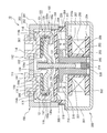
- FIG. 1 is a sectional view showing an example of an electromagnetic switch according to the present invention
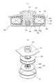
- FIG. 2 is an exploded perspective view of an arc-extinguishing chamber.
- reference numeral 10 denotes an electromagnetic contactor
- the electromagnetic contactor 10 includes a contact device 100 in which a contact mechanism is disposed and an electromagnet unit 200 for driving the contact device 100.
- the contact device 100 has an arc-extinguishing chamber 102 that houses the contact mechanism 101.
- the arc-extinguishing chamber 102 closes the upper end of the metal rectangular cylinder 104 having a flange portion 103 protruding outward at the lower end portion made of metal and the metal rectangular cylinder 104.
- a fixed contact support insulating substrate 105 formed of a flat ceramic insulating substrate.
- the metal square cylindrical body 104 is seal-joined and fixed to the upper magnetic yoke 210 of the electromagnet unit 200 which the flange part 103 mentions later. Further, through holes 106 and 107 through which a pair of fixed contacts 111 and 112, which will be described later, are inserted are formed in the central portion of the fixed contact support insulating substrate 105 at a predetermined interval. A metallizing process is applied to positions around the through holes 106 and 107 on the upper surface side of the fixed contact support insulating substrate 105 and in contact with the rectangular cylinder 104 on the lower surface side.
- copper foils are formed around the through holes 106 and 107 and in contact with the rectangular cylinder 104 in a state where the plurality of fixed contact support insulating substrates 105 are arranged in a matrix on a plane.
- the contact mechanism 101 includes a pair of fixed contacts 111 and 112 inserted and fixed in the through holes 106 and 107 of the fixed contact support insulating substrate 105 of the arc-extinguishing chamber 102.
- Each of the fixed contacts 111 and 112 includes a support conductor 114 having an outwardly projecting flange at an upper end inserted into the through holes 106 and 107 of the fixed contact support insulating substrate 105, and the support conductor 114.
- a C-shaped portion 115 disposed on the lower surface side of the fixed contact support insulating substrate 105 and opened at the inner side.
- the C-shaped portion 115 includes an upper plate portion 116 extending outward along the lower surface of the fixed contact support insulating substrate 105, an intermediate plate portion 117 extending downward from the outer end of the upper plate portion 116, and the intermediate plate An L-shape formed by the middle plate portion 117 and the lower plate portion 118 with the lower plate portion 118 extending inward from the lower end side of the portion 117 in parallel with the upper plate portion 116, ie, the facing direction of the fixed contacts 111 and 112 It is formed in C shape which added the upper board part 116 to the shape.
- the support conductor portion 114 and the C-shaped portion 115 are formed in the through holes 120 formed in the upper plate portion 116 of the C-shaped portion 115 with the pins 114 a formed to project from the lower end surface of the support conductor portion 114.
- it is fixed by brazing in the inserted state.
- Fixing of the support conductor portion 114 and the C-shaped portion 115 is not limited to brazing, and the pin 114a is fitted in the through hole 120, or an external thread is formed on the pin 114a, and an internal thread is formed in the through hole 120. The two may be screwed together.
- the C-shaped portions 115 of the fixed contacts 111 and 112 are each fitted with an insulating cover 121 made of a synthetic resin material for restricting the generation of an arc.
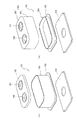
- the insulating cover 121 covers the inner peripheral surfaces of the upper plate portion 116 and the middle plate portion 117 of the C-shaped portion 115, as shown in FIGS. 3 (a) and 3 (b).
- the insulating cover 121 extends upward and outward from the L-shaped plate portion 122 along the inner peripheral surfaces of the upper plate portion 116 and the intermediate plate portion 117 and the front and rear end portions of the L-shaped plate portion 122, respectively.
- the insulating cover 121 causes the fitting portion 125 to face the small diameter portion 114b of the support conductor portion 114 of the fixed contacts 111 and 112, and then, As shown in FIG. 3C, the fitting portion 125 is engaged with the small diameter portion 114 b of the support conductor portion 114 by pushing the insulating cover 121.
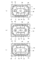
- the contact storage case 102 after the fixed contacts 111 and 112 are attached is viewed from the upper opening with the fixed contact support insulating substrate 105 facing downward.
- the insulating cover 121 is inserted between the fixed contacts 111 and 112 in a state of being upside down with respect to FIGS. 3 (a) to 3 (c).
- the insulating cover 121 is pushed outward as shown in FIG. 4 (c) in a state where the fitting portion 125 is in contact with the fixed contact support insulating substrate 105.
- the fitting portion 125 is fitted and fixed to the small diameter portion 114 b of the support conductor portion 114 of the fixed contacts 111 and 112.
- movable contact 130 is arranged so that both ends may be arranged in C character-like part 115 of fixed contacts 111 and 112.
- the movable contact 130 is supported by a connecting shaft 131 fixed to a movable plunger 215 of an electromagnet unit 200 described later.
- the movable contact 130 is formed with a recess 132 in which the vicinity of the connection shaft 131 in the central portion protrudes downward, and a through hole 133 for inserting the connection shaft 131 is formed in the recess 132 It is formed.
- the connecting shaft 131 has a flange portion 131a protruding outward at the upper end.
- the connection shaft 131 is inserted into the contact spring 134 from the lower end side, and then inserted through the through hole 133 of the movable contact 130 so that the upper end of the contact spring 134 abuts against the flange portion 131 a.
- the movable contact 130 is positioned by, for example, a C ring 135 so as to obtain a force.
- the movable contact 130 is separated from the contact portions at both ends and the contact portion 118a of the lower plate 118 of the C-shaped portion 115 of the fixed contacts 111 and 112 at a predetermined interval. Further, in the movable position, the contact portions at both ends contact the contact portion 118a of the lower plate portion 118 of the C-shaped portion 115 of the fixed contacts 111 and 112 at a predetermined position by the contact spring 134 in the closing position. It is set to
- Storage pockets 141 and 142 are formed.
- the arc extinguishing permanent magnets 143 and 144 are inserted and fixed to the magnet storage pockets and 141 and 142, respectively.
- the arc extinguishing permanent magnets 143 and 144 are magnetized in such a way that their opposing surfaces have the same pole, for example, the N pole in the thickness direction. Further, as shown in FIG. 5, both end portions in the left-right direction of the arc extinguishing permanent magnets 143 and 144 are facing positions of the contact portions 118 a of the fixed contacts 111 and 112 and the contact portions of the movable contact 130. It is set to be slightly inside. Further, arc extinguishing spaces 145 and 146 are formed on the outer sides in the left-right direction of the magnet storage pockets 141 and 142, respectively.
- the arc extinguishing permanent magnets 143 and 144 can be brought close to the movable contact 130.
- the magnetic flux ⁇ emitted from the N pole side of both arc extinguishing permanent magnets 143 and 144 is the contact point of the contact portion 118a of the fixed contacts 111 and 112 and the movable contact 130
- the portion facing the portion 130a is traversed with a large magnetic flux density from the inside to the outside in the left-right direction.
- the direction of the current in the on state is as shown in FIG. Flow to the fixed contact 112 through the movable contact 130.
- the contact portion 118 a of the fixed contacts 111 and 112 and the contact portion 130 a of the movable contact 130 are separated. An arc occurs between them.
- the electromagnet unit 200 has a flat U-shaped magnetic yoke 201 when viewed from the side, and a cylindrical auxiliary yoke 203 is fixed to the central portion of the bottom plate portion 202 of the magnetic yoke 201. There is. A spool 204 as a plunger driving unit is disposed outside the cylindrical auxiliary yoke 203.
- the spool 204 has a central cylindrical portion 205 through which the cylindrical auxiliary yoke 203 is inserted, a lower flange portion 206 projecting radially outward from the lower end portion of the central cylindrical portion 205, and a little slightly from the upper end of the central cylindrical portion 205.
- An upper flange portion 207 protrudes radially outward from the lower side.
- the exciting coil 208 is wound in a storage space formed by the central cylindrical portion 205, the lower flange portion 206, and the upper flange portion 207.
- the upper magnetic yoke 210 is fixed between the upper ends of the magnetic yokes 201 which are open ends.
- a through hole 210a facing the central cylindrical portion 205 of the spool 204 is formed in the central portion.
- a movable plunger 215, in which a return spring 214 is disposed between the bottom portion and the bottom plate portion 202 of the magnetic yoke 201, is slidably disposed in the vertical direction.
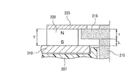
- the movable plunger 215 is formed with a circumferential flange portion 216 projecting radially outward at an upper end portion projecting upward from the upper magnetic yoke 210.
- a permanent magnet 220 formed annularly is fixed on the upper surface of the upper magnetic yoke 210 so as to surround the peripheral flange portion 216 of the movable plunger 215.
- the permanent magnet 220 has a through hole 221 surrounding the circumferential ridge portion 216.
- the permanent magnet 220 is magnetized so that the upper end side is, for example, an N pole in the vertical direction, that is, the thickness direction, and the lower end side is an S pole.
- the shape of the through hole 221 of the permanent magnet 220 can be made into the shape according to the shape of the peripheral collar part 216, and the shape of an outer peripheral surface can be made arbitrary shapes, such as circular and a square.
- an auxiliary yoke 225 having a through hole 224 of the same outer diameter as the permanent magnet 220 and having an inner diameter smaller than the outer diameter of the peripheral flange portion 216 of the movable plunger 215 is fixed to the upper end surface of the permanent magnet 220.
- the peripheral flange portion 216 of the movable plunger 215 is opposed to the lower surface of the auxiliary yoke 225.
- the stroke L of the movable plunger 215 can be determined only by the thickness T of the permanent magnet 220 and the thickness t of the peripheral flange portion 216, and variations in the stroke L can be minimized. In particular, it is more effective when the stroke is small with a small size magnetic contactor.
- the permanent magnet 220 is formed in an annular shape, the number of parts can be reduced and the cost can be reduced as compared with the case where two permanent magnets are disposed on the left and right as described in Patent Documents 1 and 2. .
- the peripheral flange portion 216 of the movable plunger 215 is disposed in the vicinity of the inner peripheral surface of the through hole 221 formed in the permanent magnet 220, there is no waste in the closed circuit for passing the magnetic flux generated by the permanent magnet 220. And the magnetic force of the permanent magnet can be used efficiently.
- a connecting shaft 131 supporting the movable contact 130 is screwed to the upper end surface of the movable plunger 215. Then, in the released state, the movable plunger 215 is biased upward by the return spring 214, and the upper surface of the circumferential flange portion 216 is in the released position where it abuts on the lower surface of the auxiliary yoke 225. In this state, the contact portion 130a of the movable contact 130 is separated upward from the contact portions 118a of the fixed contacts 111 and 112, and the current is cut off.
- the peripheral flange portion 216 of the movable plunger 215 is attracted to the auxiliary yoke 225 by the magnetic force of the permanent magnet 220, and combined with the biasing force of the return spring 214, the movable plunger 215 is not moved by external vibration or impact.
- the state of being in contact with the auxiliary yoke 225 is ensured without moving downward in preparation.
- the gap g1 between the lower surface of the peripheral flange portion 216 of the movable plunger 215 and the upper surface of the upper magnetic yoke 210, the outer peripheral surface of the movable plunger 215 and the upper magnetic yoke A gap g2 between the through hole 210a of 210 and a gap g3 between the outer peripheral surface of the movable plunger 215 and the cylindrical auxiliary yoke 203, and a gap g4 between the lower surface of the movable plunger 215 and the upper surface of the bottom plate portion 202 of the magnetic yoke 201
- the relationship is set as follows. g1 ⁇ g2 and g3 ⁇ g4
- the movable plunger 215 passes from the movable flange 215 through the peripheral flange portion 216 and between the peripheral ridge portion 216 and the upper magnetic yoke 210.
- the upper magnetic yoke 210 is reached through the gap g1.
- a closed magnetic path is formed from the upper magnetic yoke 210 through the U-shaped magnetic yoke 201 through the cylindrical auxiliary yoke 203 to the movable plunger 215.
- the magnetic flux density of the gap g1 between the lower surface of the peripheral flange portion 216 of the movable plunger 215 and the upper surface of the upper magnetic yoke 210 can be increased, generating a larger attractive force to return the movable plunger 215 to the spring. It is lowered against the biasing force of 214 and the attraction force of the permanent magnet 220. Therefore, the contact portion 130a of the movable contact 130 connected to the movable plunger 215 via the connection shaft 131 is brought into contact with the contact portions 118a of the fixed contacts 111 and 112, and the fixed contact 111 through the movable contact 130 A current path toward the fixed contact 112 is formed and is in the closed state.
- the movable plunger 215 is covered with a cap 230 formed of a nonmagnetic material and having a bottomed cylindrical shape, and a flange portion 231 formed by extending radially outward at the open end of the cap 230 is an upper magnetic yoke It is seal-bonded to the lower surface of 210.
- a sealed container in which the arc-extinguishing chamber 102 and the cap 230 are in communication via the through hole 210 a of the upper magnetic yoke 210 is formed. Further, in a sealed container formed by the arc extinguishing chamber 102 and the cap 230, a gas such as hydrogen gas, nitrogen gas, a mixed gas of hydrogen and nitrogen, air, SF 6 or the like is enclosed.
- the fixed contactor 111 is connected to, for example, a power supply that supplies a large current, and the fixed contactor 112 is connected to the load.
- the excitation coil 208 in the electromagnet unit 200 is in the non-excitation state, and the electromagnet unit 200 is in the release state where the excitation force for lowering the movable plunger 215 is not generated.
- the movable plunger 215 is biased upward away from the upper magnetic yoke 210 by the return spring 214.
- both the biasing force of the return spring 214 and the suction force of the annular permanent magnet 220 act on the movable plunger 215, so the movable plunger 215 is carelessly vibrated by external vibration or impact. It is possible to prevent malfunctioning without falling.
- the exciting coil 208 of the electromagnet unit 200 is excited from this released state, an excitation force is generated by the electromagnet unit 200 and the movable plunger 215 resists the biasing force of the return spring 214 and the attraction force of the annular permanent magnet 220. Push down.
- the gap g4 between the bottom surface of the movable plunger 215 and the bottom plate portion 202 of the magnetic yoke 201 is large, and there is almost no magnetic flux passing through the gap g4.
- the cylindrical auxiliary yoke 203 is opposed to the lower outer peripheral surface of the movable plunger 215, and the gap g3 between the cylindrical auxiliary yoke 203 and the cylindrical auxiliary yoke 203 is set smaller than the gap g4.
- a magnetic path is formed between the movable plunger 215 and the bottom plate portion 202 of the magnetic yoke 201 through the cylindrical yoke 203. Furthermore, the gap between the lower magnetic pole portion 216 of the movable plunger 215 and the upper magnetic yoke 210 in comparison with the gap g2 between the outer peripheral surface of the movable plunger 215 and the inner peripheral surface of the through hole 210a of the upper magnetic yoke 210 g1 is set small.
- the movable plunger 215 is quickly lowered against the biasing force of the return spring 214 and the suction force of the annular permanent magnet 220. Thereby, the descent of the movable plunger 215 is stopped by the lower surface of the peripheral flange portion 216 coming into contact with the upper surface of the upper magnetic yoke 210 as shown in FIG. 9B.
- the movable contact 130 coupled to the movable plunger 215 via the connecting shaft 131 also descends, and the contact portion 130 a thereof is the contact portion 118 a of the fixed contacts 111 and 112. Contact with the contact pressure of the contact spring 13.
- the fixed contacts 111 and 112 have the C-shaped portion 115 formed by the upper plate portion 116, the intermediate plate portion 117 and the lower plate portion 118, so the upper plate portion 116 and the lower portion A current in the reverse direction flows between the plate portion 118 and the movable contact 130 opposed thereto.
- the movable contact 130 is used as the contact portion 118a of the fixed contacts 111 and 112 according to Fleming's left law. It can generate the Lorentz force to press. This Lorentz force can resist the electromagnetic repulsion in the opening direction generated between the contact portions 118a of the fixed contacts 111 and 112 and the contact portion 130a of the movable contact 130, and the contact portions of the movable contact 130 The opening of the electrode 130a can be reliably prevented.
- the pressing force of the contact spring 134 supporting the movable contact 130 can be reduced, and the thrust generated by the exciting coil 208 can be reduced accordingly, and the overall configuration of the electromagnetic contactor can be miniaturized. can do.
- the excitation of the exciting coil 208 of the electromagnet unit 200 is stopped.
- the contact device 100 can be miniaturized.
- the magnetic field generated by the current flowing through the intermediate plate portion 117 is shielded by the magnetic material plate 119 . Therefore, the magnetic field due to the arc generated between the contact portion 118a of the fixed contacts 111 and 112 and the contact portion 130a of the movable contact 130 does not interfere with the magnetic field generated due to the current flowing through the intermediate plate portion 117. It is possible to prevent the arc from being affected by the magnetic field generated by the current flowing through the plate portion 117.
- the magnetic flux from the N pole is viewed in plan as shown in FIG.
- the arc generating portion of the opposing portion of the contact portion 118a of the fixed contact 111 for each arc extinguishing permanent magnet 143 and 144 and the contact portion 130a of the movable contact 130 is the longitudinal direction of the movable contact 130
- the magnetic field is formed by crossing the inside from the outside to the south pole.
- the arc generating portion of the contact portion 118a of the fixed contact 112 and the contact portion 130a of the movable contact 130 is traversed in the longitudinal direction of the movable contact 130 from the inside to the outside to reach the S pole to form a magnetic field. Therefore, the magnetic fluxes of the arc extinguishing permanent magnets 143 and 144 are both between the contact portion 118a of the fixed contact 111 and the contact portion 130a of the movable contact 130, and the contact of the contact portion 118a of the fixed contact 112 and the movable contact 130 In the longitudinal direction of the movable contact 130, the portions 130a cross in opposite directions.
- An arc generated between the contact portion 118a of the fixed contact 111 and the contact portion 130a of the movable contact 130 by the Lorentz force F travels in the arc extinguishing space 145 from the side surface of the contact portion 118a of the fixed contact 111. It is greatly stretched and extinguished to reach the upper surface side of the movable contact 130 through it. Further, in the arc extinguishing space 145, the magnetic flux flows downward and upward with respect to the direction of the magnetic flux between the contact portion 118a of the fixed contact 111 and the contact portion 130a of the movable contact 130 on the lower side and the upper side. I will lean.
- the arc drawn into the arc extinguishing space 145 is further stretched in the direction of the corner of the arc extinguishing space 145 by the inclined magnetic flux, the arc length can be increased, and a good breaking performance can be obtained. .
- An arc generated between the contact portion 118 a of the fixed contact 112 and the movable contact 130 by the Lorentz force F passes from the upper surface side of the movable contact 130 through the arc extinguishing space 145 of the fixed contact 112. It is greatly stretched and extinguished to reach the side. Further, as described above, in the arc extinguishing space 145, the lower side and the upper side of the lower side and the upper side with respect to the direction of the magnetic flux between the contact portion 118a of the fixed contact 112 and the contact portion 130a of the movable contact 130. The magnetic flux is inclined upward.
- the arc drawn into the arc extinguishing space 145 is further stretched in the direction of the corner of the arc extinguishing space 145 by the inclined magnetic flux, the arc length can be increased, and a good breaking performance can be obtained.
- the regenerative current flows from the load side to the DC power supply side in the closed state of the magnetic contactor 10
- the direction of the current in FIG.
- the same arc-extinguishing function is exhibited except that the Lorentz force F acts on the side of the arc extinguishing space 146 and the arc is stretched to the side of the arc extinguishing space 146.
- the arc extinguishing permanent magnets 143 and 144 are disposed in the magnet storage pockets 141 and 142 formed in the insulating cylinder 140, the arc directly contacts the arc extinguishing permanent magnets 143 and 144. I have not. Therefore, the magnetic characteristics of the arc extinguishing permanent magnets 143 and 144 can be stably maintained, and the interrupting performance can be stabilized.
- the inner peripheral surface of the metal contact storage case 102 can be covered and insulated by the insulating cylinder 140, there is no short circuit of the arc at the time of the current interruption, and the current interruption can be surely performed. Furthermore, since the insulating function, the positioning function of the arc extinguishing permanent magnets 143 and 144, and the arc protecting function of the arc extinguishing permanent magnets 143 and 144 can be performed by one insulating cylinder 140, the manufacturing cost can be reduced. It can be reduced.
- the C-shaped portion 115 of the fixed contacts 111 and 112 and the contact spring 134 for applying the contact pressure of the movable contact 130 are arranged in parallel.
- the height of the contact mechanism 101 can be shortened as compared with the case where the fixed contact, the movable contact, and the contact spring are arranged in series. Therefore, the contact device 100 can be miniaturized.
- the contact storage case 102 is formed by brazing a rectangular cylindrical body 104 and a flat fixed contact support insulating substrate 105 for closing and holding the upper surface of the upper surface and fixing and holding the fixed contacts 111 and 112 by brazing. I have to.
- the fixed contact support insulating substrates 105 can be arranged in close contact longitudinally and horizontally on the same plane, and a plurality of fixed contact support insulating substrates 105 can be metallized at one time, improving productivity. It can be done.
- the fixed contacts 111 and 112 can be brazed and supported on the fixed contact support insulating substrate 105 and then brazed to the rectangular cylinder 104, so that the fixed contacts 111 and 112 can be easily fixed and held. Therefore, the configuration of the brazing jig is simple, and the cost of the assembling jig can be reduced.
- the flatness and warpage of the fixed contact support insulating substrate 105 can be more easily suppressed and managed as compared with the case where the contact storage case 102 is formed in a bowl shape.
- the contact storage case 102 can be collectively manufactured in large quantities, and the manufacturing cost can be reduced.
- the annular permanent magnet 220 magnetized in the movable direction of the movable plunger 215 is disposed on the upper magnetic yoke 210, and the auxiliary yoke 225 is formed on the upper surface thereof.
- the biasing force of the return spring 214 can be reduced, and the total load by the contact spring 134 and the return spring 214 can be reduced. Therefore, it is possible to reduce the attraction force generated in the exciting coil 208 according to the decrease in the total load, and to reduce the magnetomotive force of the exciting coil 208. Therefore, the axial length of the spool 204 can be shortened, and the height of the movable plunger 215 of the electromagnet unit 200 in the movable direction can be reduced.
- the entire configuration of the electromagnetic contactor 10 can be significantly shortened, and miniaturization can be achieved.
- the peripheral flange portion 216 of the movable plunger 215 in the inner peripheral surface of the annular permanent magnet 220, there is no waste in the closed magnetic path through which the magnetic flux generated from the annular permanent magnet 220 passes, and leakage flux is reduced. Can be used efficiently.
- the stroke of the movable plunger 215 can be made thicker and movable than the annular permanent magnet 220.
- the thickness can be adjusted with the thickness of the peripheral flange portion 216 of the plunger 215. For this reason, it is possible to minimize the cumulative number of parts and the shape tolerance that affect the stalk of the movable plunger 215.
- the stroke adjustment of the movable plunger 215 is performed only by the thickness of the annular permanent magnet 220 and the thickness of the peripheral flange portion 216 of the movable plunger 215, the variation in the stroke can be minimized.
- a square tube portion 301 and a top plate portion 302 closing the upper end thereof are integrally formed of a ceramic or a synthetic resin material to form a bowl-like body 303.
- the open end face side of the bowl-like body 303 may be metallized to form a metal foil, and the metal connection member 304 may be seal-joined to the metal foil to form the arc-extinguishing chamber 102.
- the contact mechanism 101 is not limited to the structure of the said embodiment, either, The contact mechanism of arbitrary structures is applicable.
- an L-shaped portion 160 having a shape in which the upper plate portion 116 of the C-shaped portion 115 is omitted may be connected to the support conductor portion 114.
- the magnetic flux generated by the current flowing through the vertical plate of the L-shaped part 160 is fixed to the fixed contacts 111 and 112 and the movable contact It can act on the contact portion with 130. For this reason, it is possible to increase the magnetic flux density at the contact portion between the fixed contacts 111 and 112 and the movable contact 130 to generate the Lorentz force against the electromagnetic repulsive force.
- the concave portion 132 may be omitted and formed in a flat plate shape.
- the connecting shaft 131 is screwed to the movable plunger 215 has been described, but not limited to screwing, any connection method can be applied, and furthermore, the movable plunger 215 and the connecting shaft You may make it form with 131 integrally.
- connection between the connecting shaft 131 and the movable contact 130 forms the flange portion 131a at the tip of the connecting shaft 131, and after the contact spring 134 and the movable contact 130 are inserted, the lower end of the movable contact 130 is
- a positioning large-diameter portion that protrudes in the radial direction is formed at the C-ring position of the connecting shaft 131, the movable contact 130 is made to abut on this, and then the contact spring 134 is disposed. It may be fixed by a ring.
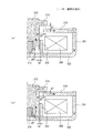
- the magnetic yoke 201 is formed in a cylindrical shape with a bottom as shown in FIGS. 13A and 13B, and the auxiliary yoke 203 is an annular plate portion 203a along the bottom plate portion 202 of the magnetic yoke 201 and this circle. You may make it comprise with the cylindrical part 203b which stands up upwards from the internal peripheral surface of the cyclic
- a through hole 202a is formed in the bottom plate portion 202 of the U-shaped magnetic yoke 210, and a convex auxiliary yoke 203 is fitted in the through hole 202a.
- the small diameter portion 203c of the auxiliary yoke 203 may be inserted into the insertion hole 217 formed in the movable plunger 215.
Landscapes
- Physics & Mathematics (AREA)
- Electromagnetism (AREA)
- Contacts (AREA)
- Arc-Extinguishing Devices That Are Switches (AREA)
- Electromagnets (AREA)
Abstract
Priority Applications (4)
| Application Number | Priority Date | Filing Date | Title |
|---|---|---|---|
| KR1020137030017A KR20140027990A (ko) | 2011-05-19 | 2012-04-03 | 전자 접촉기 |
| CN201280023776.4A CN103534779B (zh) | 2011-05-19 | 2012-04-03 | 电磁接触器 |
| EP12785142.6A EP2711960A4 (fr) | 2011-05-19 | 2012-04-03 | Contacteur électromagnétique |
| US14/115,263 US9202652B2 (en) | 2011-05-19 | 2012-04-03 | Electromagnetic contactor |
Applications Claiming Priority (2)
| Application Number | Priority Date | Filing Date | Title |
|---|---|---|---|
| JP2011112906A JP5727860B2 (ja) | 2011-05-19 | 2011-05-19 | 電磁接触器 |
| JP2011-112906 | 2011-05-19 |
Publications (1)
| Publication Number | Publication Date |
|---|---|
| WO2012157170A1 true WO2012157170A1 (fr) | 2012-11-22 |
Family
ID=47176525
Family Applications (1)
| Application Number | Title | Priority Date | Filing Date |
|---|---|---|---|
| PCT/JP2012/002327 Ceased WO2012157170A1 (fr) | 2011-05-19 | 2012-04-03 | Contacteur électromagnétique |
Country Status (6)
| Country | Link |
|---|---|
| US (1) | US9202652B2 (fr) |
| EP (1) | EP2711960A4 (fr) |
| JP (1) | JP5727860B2 (fr) |
| KR (1) | KR20140027990A (fr) |
| CN (1) | CN103534779B (fr) |
| WO (1) | WO2012157170A1 (fr) |
Cited By (4)
| Publication number | Priority date | Publication date | Assignee | Title |
|---|---|---|---|---|
| WO2014080555A1 (fr) * | 2012-11-26 | 2014-05-30 | 富士電機機器制御株式会社 | Contacteur d'électroaimant |
| WO2014154056A3 (fr) * | 2013-03-29 | 2014-11-13 | 厦门宏发电力电器有限公司 | Relais à verrouillage magnétique présentant une structure solénoïde asymétrique |
| CN104704598A (zh) * | 2012-12-05 | 2015-06-10 | 富士电机机器制御株式会社 | 电磁接触器 |
| WO2023281980A1 (fr) * | 2021-07-08 | 2023-01-12 | 富士電機機器制御株式会社 | Plaque non magnétique, contacteur électromagnétique, matériau non magnétique et procédé de fabrication |
Families Citing this family (9)
| Publication number | Priority date | Publication date | Assignee | Title |
|---|---|---|---|---|
| JP6171320B2 (ja) * | 2012-12-12 | 2017-08-02 | 富士電機機器制御株式会社 | 電磁接触器 |
| CN105428161A (zh) * | 2014-09-03 | 2016-03-23 | 苏州磁明科技有限公司 | 机电式可锁定型继电器及其使用方法 |
| JP6287727B2 (ja) * | 2014-09-25 | 2018-03-07 | アンデン株式会社 | 電磁継電器 |
| JP6274229B2 (ja) * | 2016-01-27 | 2018-02-07 | 富士電機機器制御株式会社 | 接点装置及びこれを使用した電磁接触器 |
| JP7103262B2 (ja) * | 2019-02-19 | 2022-07-20 | 富士電機機器制御株式会社 | 電磁接触器 |
| CN112713053B (zh) * | 2019-10-25 | 2025-11-11 | 首瑞(天津)电气设备有限公司 | 一种开关管 |
| CN114946006B (zh) * | 2020-01-23 | 2025-06-10 | 三菱电机株式会社 | 开闭器 |
| JP7380608B2 (ja) * | 2021-01-22 | 2023-11-15 | 富士電機機器制御株式会社 | 密閉型電磁接触器 |
| CN115083842B (zh) * | 2022-07-05 | 2025-08-26 | 上海电器科学研究所(集团)有限公司 | 接触器的触头灭弧系统以及接触器 |
Citations (5)
| Publication number | Priority date | Publication date | Assignee | Title |
|---|---|---|---|---|
| JPH01268005A (ja) * | 1988-04-19 | 1989-10-25 | Omron Tateisi Electron Co | 電磁石装置 |
| JPH0291901A (ja) | 1988-09-29 | 1990-03-30 | Mitsubishi Electric Corp | 有極電磁石装置 |
| JPH10125196A (ja) * | 1996-07-31 | 1998-05-15 | Matsushita Electric Works Ltd | 封止接点装置 |
| US5959519A (en) | 1996-03-06 | 1999-09-28 | Siemens Ag | Electromagnetic switching device |
| JP2010062079A (ja) * | 2008-09-05 | 2010-03-18 | Mitsubishi Electric Corp | 有極電磁石、電磁接触器、電磁開閉器、及び有極電磁石の製造方法 |
Family Cites Families (15)
| Publication number | Priority date | Publication date | Assignee | Title |
|---|---|---|---|---|
| US2121657A (en) * | 1936-02-01 | 1938-06-21 | James B Fisher | Electromagnetic control means |
| US3444490A (en) * | 1966-09-30 | 1969-05-13 | Westinghouse Electric Corp | Electromagnetic structures for electrical control devices |
| US4345224A (en) * | 1981-01-30 | 1982-08-17 | General Electric Company | Contact spring arrangement |
| JP3321963B2 (ja) * | 1994-02-22 | 2002-09-09 | 株式会社デンソー | プランジャ型電磁継電器 |
| US5917394A (en) * | 1998-12-01 | 1999-06-29 | Fuchs; Michael J | Solenoid switch modified for higher current passage |
| JP4747734B2 (ja) * | 2005-08-22 | 2011-08-17 | 富士電機機器制御株式会社 | 有極電磁石 |
| BRPI0520792A2 (pt) * | 2005-12-22 | 2009-06-23 | Siemens Ag | método e dispositivo para operar um dispositivo de comutação |
| JP4765761B2 (ja) * | 2006-05-12 | 2011-09-07 | オムロン株式会社 | 電磁継電器 |
| US7852178B2 (en) * | 2006-11-28 | 2010-12-14 | Tyco Electronics Corporation | Hermetically sealed electromechanical relay |
| WO2008135670A1 (fr) | 2007-03-27 | 2008-11-13 | Schneider Electric Industries Sas | Actionneur electromagnetique bistable, circuit de commande d'un actionneur electromagnetique a double bobines et actionneur electromagnetique a double bobines comportant un tel circuit de commande |
| JP2010192416A (ja) * | 2009-01-21 | 2010-09-02 | Panasonic Electric Works Co Ltd | 封止接点装置 |
| JP5521852B2 (ja) * | 2010-03-30 | 2014-06-18 | アンデン株式会社 | 電磁継電器 |
| JP5307779B2 (ja) * | 2010-08-31 | 2013-10-02 | 富士電機機器制御株式会社 | 電磁開閉器 |
| KR20130124503A (ko) * | 2010-11-01 | 2013-11-14 | 니뽄 도쿠슈 도교 가부시키가이샤 | 계전기 |
| JP5724616B2 (ja) * | 2011-05-18 | 2015-05-27 | 株式会社デンソー | 電磁スイッチ |
-
2011
- 2011-05-19 JP JP2011112906A patent/JP5727860B2/ja active Active
-
2012
- 2012-04-03 KR KR1020137030017A patent/KR20140027990A/ko not_active Withdrawn
- 2012-04-03 US US14/115,263 patent/US9202652B2/en active Active
- 2012-04-03 WO PCT/JP2012/002327 patent/WO2012157170A1/fr not_active Ceased
- 2012-04-03 CN CN201280023776.4A patent/CN103534779B/zh active Active
- 2012-04-03 EP EP12785142.6A patent/EP2711960A4/fr not_active Withdrawn
Patent Citations (5)
| Publication number | Priority date | Publication date | Assignee | Title |
|---|---|---|---|---|
| JPH01268005A (ja) * | 1988-04-19 | 1989-10-25 | Omron Tateisi Electron Co | 電磁石装置 |
| JPH0291901A (ja) | 1988-09-29 | 1990-03-30 | Mitsubishi Electric Corp | 有極電磁石装置 |
| US5959519A (en) | 1996-03-06 | 1999-09-28 | Siemens Ag | Electromagnetic switching device |
| JPH10125196A (ja) * | 1996-07-31 | 1998-05-15 | Matsushita Electric Works Ltd | 封止接点装置 |
| JP2010062079A (ja) * | 2008-09-05 | 2010-03-18 | Mitsubishi Electric Corp | 有極電磁石、電磁接触器、電磁開閉器、及び有極電磁石の製造方法 |
Non-Patent Citations (1)
| Title |
|---|
| See also references of EP2711960A4 * |
Cited By (8)
| Publication number | Priority date | Publication date | Assignee | Title |
|---|---|---|---|---|
| WO2014080555A1 (fr) * | 2012-11-26 | 2014-05-30 | 富士電機機器制御株式会社 | Contacteur d'électroaimant |
| JP2014107050A (ja) * | 2012-11-26 | 2014-06-09 | Fuji Electric Fa Components & Systems Co Ltd | 電磁接触器 |
| CN104704598A (zh) * | 2012-12-05 | 2015-06-10 | 富士电机机器制御株式会社 | 电磁接触器 |
| US9520246B2 (en) | 2012-12-05 | 2016-12-13 | Fuji Electric Fa Components & Systems Co., Ltd. | Electromagnetic contactor |
| WO2014154056A3 (fr) * | 2013-03-29 | 2014-11-13 | 厦门宏发电力电器有限公司 | Relais à verrouillage magnétique présentant une structure solénoïde asymétrique |
| US9640336B2 (en) | 2013-03-29 | 2017-05-02 | Xiamen Hongfa Electric Power Controls Co., Ltd. | Magnetic latching relay having asymmetrical solenoid structure |
| WO2023281980A1 (fr) * | 2021-07-08 | 2023-01-12 | 富士電機機器制御株式会社 | Plaque non magnétique, contacteur électromagnétique, matériau non magnétique et procédé de fabrication |
| JP7586003B2 (ja) | 2021-07-08 | 2024-11-19 | 富士電機機器制御株式会社 | 非磁性板、電磁接触器、非磁性素材、および製造方法 |
Also Published As
| Publication number | Publication date |
|---|---|
| CN103534779A (zh) | 2014-01-22 |
| EP2711960A1 (fr) | 2014-03-26 |
| JP5727860B2 (ja) | 2015-06-03 |
| JP2012243583A (ja) | 2012-12-10 |
| CN103534779B (zh) | 2016-08-17 |
| EP2711960A4 (fr) | 2015-06-10 |
| US20140062625A1 (en) | 2014-03-06 |
| KR20140027990A (ko) | 2014-03-07 |
| US9202652B2 (en) | 2015-12-01 |
Similar Documents
| Publication | Publication Date | Title |
|---|---|---|
| JP5684649B2 (ja) | 電磁接触器 | |
| JP5965218B2 (ja) | 電磁接触器 | |
| WO2012157170A1 (fr) | Contacteur électromagnétique | |
| JP5727862B2 (ja) | 電磁接触器 | |
| EP2711965B1 (fr) | Contacteur électromagnétique | |
| WO2012157176A1 (fr) | Contacteur électromagnétique | |
| JP5689741B2 (ja) | 電磁接触器 | |
| JP5767508B2 (ja) | 電磁接触器 | |
| JP5727861B2 (ja) | 電磁接触器 | |
| WO2012157175A1 (fr) | Procédé d'assemblage de chambre d'extinction d'arc pour contacteur électromagnétique | |
| WO2014076865A1 (fr) | Commutateur électromagnétique | |
| WO2014080555A1 (fr) | Contacteur d'électroaimant |
Legal Events
| Date | Code | Title | Description |
|---|---|---|---|
| 121 | Ep: the epo has been informed by wipo that ep was designated in this application |
Ref document number: 12785142 Country of ref document: EP Kind code of ref document: A1 |
|
| WWE | Wipo information: entry into national phase |
Ref document number: 2012785142 Country of ref document: EP |
|
| ENP | Entry into the national phase |
Ref document number: 20137030017 Country of ref document: KR Kind code of ref document: A |
|
| WWE | Wipo information: entry into national phase |
Ref document number: 14115263 Country of ref document: US |
|
| NENP | Non-entry into the national phase |
Ref country code: DE |