WO2012157236A1 - Dispositif adoucisseur d'eau par régénération - Google Patents
Dispositif adoucisseur d'eau par régénération Download PDFInfo
- Publication number
- WO2012157236A1 WO2012157236A1 PCT/JP2012/003105 JP2012003105W WO2012157236A1 WO 2012157236 A1 WO2012157236 A1 WO 2012157236A1 JP 2012003105 W JP2012003105 W JP 2012003105W WO 2012157236 A1 WO2012157236 A1 WO 2012157236A1
- Authority
- WO
- WIPO (PCT)
- Prior art keywords
- water
- ion exchange
- exchange membrane
- inlet
- outlet
- Prior art date
- Legal status (The legal status is an assumption and is not a legal conclusion. Google has not performed a legal analysis and makes no representation as to the accuracy of the status listed.)
- Ceased
Links
Images


Classifications
-
- C—CHEMISTRY; METALLURGY
- C02—TREATMENT OF WATER, WASTE WATER, SEWAGE, OR SLUDGE
- C02F—TREATMENT OF WATER, WASTE WATER, SEWAGE, OR SLUDGE
- C02F1/00—Treatment of water, waste water, or sewage
- C02F1/46—Treatment of water, waste water, or sewage by electrochemical methods
- C02F1/469—Treatment of water, waste water, or sewage by electrochemical methods by electrochemical separation, e.g. by electro-osmosis, electrodialysis, electrophoresis
- C02F1/4693—Treatment of water, waste water, or sewage by electrochemical methods by electrochemical separation, e.g. by electro-osmosis, electrodialysis, electrophoresis electrodialysis
-
- B—PERFORMING OPERATIONS; TRANSPORTING
- B01—PHYSICAL OR CHEMICAL PROCESSES OR APPARATUS IN GENERAL
- B01J—CHEMICAL OR PHYSICAL PROCESSES, e.g. CATALYSIS OR COLLOID CHEMISTRY; THEIR RELEVANT APPARATUS
- B01J47/00—Ion-exchange processes in general; Apparatus therefor
- B01J47/02—Column or bed processes
- B01J47/04—Mixed-bed processes
-
- B—PERFORMING OPERATIONS; TRANSPORTING
- B01—PHYSICAL OR CHEMICAL PROCESSES OR APPARATUS IN GENERAL
- B01J—CHEMICAL OR PHYSICAL PROCESSES, e.g. CATALYSIS OR COLLOID CHEMISTRY; THEIR RELEVANT APPARATUS
- B01J47/00—Ion-exchange processes in general; Apparatus therefor
- B01J47/02—Column or bed processes
- B01J47/06—Column or bed processes during which the ion-exchange material is subjected to a physical treatment, e.g. heat, electric current, irradiation or vibration
- B01J47/08—Column or bed processes during which the ion-exchange material is subjected to a physical treatment, e.g. heat, electric current, irradiation or vibration subjected to a direct electric current
-
- B—PERFORMING OPERATIONS; TRANSPORTING
- B01—PHYSICAL OR CHEMICAL PROCESSES OR APPARATUS IN GENERAL
- B01J—CHEMICAL OR PHYSICAL PROCESSES, e.g. CATALYSIS OR COLLOID CHEMISTRY; THEIR RELEVANT APPARATUS
- B01J47/00—Ion-exchange processes in general; Apparatus therefor
- B01J47/12—Ion-exchange processes in general; Apparatus therefor characterised by the use of ion-exchange material in the form of ribbons, filaments, fibres or sheets, e.g. membranes
-
- B—PERFORMING OPERATIONS; TRANSPORTING
- B01—PHYSICAL OR CHEMICAL PROCESSES OR APPARATUS IN GENERAL
- B01J—CHEMICAL OR PHYSICAL PROCESSES, e.g. CATALYSIS OR COLLOID CHEMISTRY; THEIR RELEVANT APPARATUS
- B01J49/00—Regeneration or reactivation of ion-exchangers; Apparatus therefor
- B01J49/20—Regeneration or reactivation of ion-exchangers; Apparatus therefor of membranes
-
- B—PERFORMING OPERATIONS; TRANSPORTING
- B01—PHYSICAL OR CHEMICAL PROCESSES OR APPARATUS IN GENERAL
- B01J—CHEMICAL OR PHYSICAL PROCESSES, e.g. CATALYSIS OR COLLOID CHEMISTRY; THEIR RELEVANT APPARATUS
- B01J49/00—Regeneration or reactivation of ion-exchangers; Apparatus therefor
- B01J49/30—Electrical regeneration
-
- B—PERFORMING OPERATIONS; TRANSPORTING
- B01—PHYSICAL OR CHEMICAL PROCESSES OR APPARATUS IN GENERAL
- B01J—CHEMICAL OR PHYSICAL PROCESSES, e.g. CATALYSIS OR COLLOID CHEMISTRY; THEIR RELEVANT APPARATUS
- B01J49/00—Regeneration or reactivation of ion-exchangers; Apparatus therefor
- B01J49/75—Regeneration or reactivation of ion-exchangers; Apparatus therefor of water softeners
-
- B—PERFORMING OPERATIONS; TRANSPORTING
- B01—PHYSICAL OR CHEMICAL PROCESSES OR APPARATUS IN GENERAL
- B01D—SEPARATION
- B01D61/00—Processes of separation using semi-permeable membranes, e.g. dialysis, osmosis or ultrafiltration; Apparatus, accessories or auxiliary operations specially adapted therefor
- B01D61/42—Electrodialysis; Electro-osmosis ; Electro-ultrafiltration; Membrane capacitive deionization
- B01D61/44—Ion-selective electrodialysis
- B01D61/445—Ion-selective electrodialysis with bipolar membranes; Water splitting
-
- C—CHEMISTRY; METALLURGY
- C02—TREATMENT OF WATER, WASTE WATER, SEWAGE, OR SLUDGE
- C02F—TREATMENT OF WATER, WASTE WATER, SEWAGE, OR SLUDGE
- C02F2201/00—Apparatus for treatment of water, waste water or sewage
- C02F2201/46—Apparatus for electrochemical processes
- C02F2201/461—Electrolysis apparatus
- C02F2201/46105—Details relating to the electrolytic devices
- C02F2201/4611—Fluid flow
-
- C—CHEMISTRY; METALLURGY
- C02—TREATMENT OF WATER, WASTE WATER, SEWAGE, OR SLUDGE
- C02F—TREATMENT OF WATER, WASTE WATER, SEWAGE, OR SLUDGE
- C02F2201/00—Apparatus for treatment of water, waste water or sewage
- C02F2201/46—Apparatus for electrochemical processes
- C02F2201/461—Electrolysis apparatus
- C02F2201/46105—Details relating to the electrolytic devices
- C02F2201/46115—Electrolytic cell with membranes or diaphragms
-
- C—CHEMISTRY; METALLURGY
- C02—TREATMENT OF WATER, WASTE WATER, SEWAGE, OR SLUDGE
- C02F—TREATMENT OF WATER, WASTE WATER, SEWAGE, OR SLUDGE
- C02F2201/00—Apparatus for treatment of water, waste water or sewage
- C02F2201/46—Apparatus for electrochemical processes
- C02F2201/461—Electrolysis apparatus
- C02F2201/46105—Details relating to the electrolytic devices
- C02F2201/4618—Supplying or removing reactants or electrolyte
-
- C—CHEMISTRY; METALLURGY
- C02—TREATMENT OF WATER, WASTE WATER, SEWAGE, OR SLUDGE
- C02F—TREATMENT OF WATER, WASTE WATER, SEWAGE, OR SLUDGE
- C02F2209/00—Controlling or monitoring parameters in water treatment
- C02F2209/03—Pressure
-
- C—CHEMISTRY; METALLURGY
- C02—TREATMENT OF WATER, WASTE WATER, SEWAGE, OR SLUDGE
- C02F—TREATMENT OF WATER, WASTE WATER, SEWAGE, OR SLUDGE
- C02F2209/00—Controlling or monitoring parameters in water treatment
- C02F2209/40—Liquid flow rate
-
- C—CHEMISTRY; METALLURGY
- C02—TREATMENT OF WATER, WASTE WATER, SEWAGE, OR SLUDGE
- C02F—TREATMENT OF WATER, WASTE WATER, SEWAGE, OR SLUDGE
- C02F2303/00—Specific treatment goals
- C02F2303/16—Regeneration of sorbents, filters
-
- C—CHEMISTRY; METALLURGY
- C02—TREATMENT OF WATER, WASTE WATER, SEWAGE, OR SLUDGE
- C02F—TREATMENT OF WATER, WASTE WATER, SEWAGE, OR SLUDGE
- C02F2303/00—Specific treatment goals
- C02F2303/22—Eliminating or preventing deposits, scale removal, scale prevention
Definitions
- the present invention relates to a regenerative water softener, and more particularly to a regenerative water softener that softens water by removing cations of hardness components such as calcium and magnesium.
- This water-splitting ion exchange membrane includes, for example, a cation exchange surface and an anion exchange surface.
- the water-splitting ion exchange membrane is disposed between the first electrode and the second electrode so that the cation exchange surface faces the first electrode.
- a voltage is applied so that the first electrode becomes an anode and the second electrode becomes a cathode.
- the cation in the solution is adsorbed on the cation exchange surface of the water-splitting ion exchange membrane, the cation is removed from the solution, and the solution is softened.
- a voltage is applied so that the first electrode becomes a cathode and the second electrode becomes an anode.
- Water decomposes into hydrogen ions and hydroxide ions at the interface between the cation exchange surface and the anion exchange surface of the water-splitting ion exchange membrane. Hydrogen ions are adsorbed on the cation exchange surface, and the cations adsorbed on the cation exchange surface are released. In this way, ion exchange is performed, and the water-splitting ion exchange membrane is regenerated.
- the present invention has been made to solve such a problem, and an object of the present invention is to provide a regenerative water softening device that suppresses power consumption compared to the prior art.
- a regenerative water softening device includes a cathode and an anode, a cation exchange surface on one surface, an anion exchange surface on the other surface, and the anion exchange surface.
- the regeneration pressure between the second inlet and the second outlet at the same flow rate as that of the processing water, the differential pressure of the processing water between the first inlet and the first outlet Greater than water differential pressure.
- the present invention has an effect that it is possible to suppress power consumption in the regenerative water softening device.
- FIG. 2 is a side view schematically showing a water-splitting porous ion exchange membrane used in the regenerative water softening device of FIG. 1.
- A) is the cross-sectional view which showed typically the regeneration-type water softening apparatus which concerns on Embodiment 2 of this invention
- (b) shows typically the regeneration-type water softening apparatus of (a).
- FIG. It is the perspective view which showed typically the regenerative water softening evaluation apparatus which concerns on Embodiment 3 of this invention.
- FIG. 6 is a cross-sectional view schematically showing the regenerative water softening device in FIG. 5. It is a top view which shows the spacer used for the regeneration-type water softening apparatus of FIG. It is a conceptual diagram showing the flow of the water for a process in the regenerative water softening process of FIG. It is a conceptual diagram showing the flow of the water for reproduction
- FIG. 1 It is sectional drawing which showed typically the 1st water softening evaluation apparatus used for Example 1.
- FIG. It is a graph which shows the relationship between calcium removal capability (water softening capability) and flowing water time. It is a graph which shows the relationship between calcium desorption capability (regeneration capability of an ion exchange membrane) and flowing water time.
- a regenerative water softening device includes a cathode and an anode, a cation exchange surface on one side, an anion exchange surface on the other side, and the anion exchange
- a differential pressure between the first inlet and the first outlet, the differential pressure of the processing water between the first inlet and the second outlet at the same flow rate as the processing water. Greater than the differential pressure of water for regeneration.
- a straight line connecting the first inlet and the first outlet of the treatment water and the second of the reclaimed water may be provided so that a straight line connecting the inlet and the second outlet is perpendicular.
- the differential pressure of the treatment water generated between the first inlet and the first outlet can be set larger than the differential pressure of the regeneration water generated between the second inlet and the second outlet.
- the water-splitting ion exchange membrane connects the first inlet and the first outlet of the treatment water. It may be provided perpendicular to a straight line and parallel to a straight line connecting the second inlet and the second outlet of the water for regeneration.
- the treatment water when the treatment water is softened, the treatment water flows perpendicular to the water-splitting ion exchange membrane. For this reason, the contact probability between the hardness component ions in the water for treatment and the water-splitting ion exchange membrane is increased, the hardness component ions are efficiently adsorbed, and the water softening efficiency is improved.
- the water for regeneration flows parallel to the water-splitting ion exchange membrane. For this reason, the desorbed hardness component ions do not pass through the inside of the membrane, but quickly flow along the surface of the water-splitting ion exchange by the regeneration water. Therefore, the hardness component ions are prevented from adsorbing again on the ion exchange membrane, and the regeneration efficiency is increased.
- the water-splitting ion exchange membrane has a rectangular shape, and its long side is the treatment water.
- the short side may be provided in parallel to a straight line connecting the second inlet and the second outlet of the water for regeneration.
- the water for regeneration flows along the short side of the water-splitting ion exchange membrane.
- the desorbed hardness component ions are prevented from flowing over the surface of the water-splitting ion-exchange membrane in a short time by the regeneration water and adsorbing to the ion-exchange membrane again.
- the regeneration efficiency of the water-splitting ion exchange membrane is improved.
- the water-splitting ion exchange membrane in the third regenerative water softening device, may be formed of a porous material.
- the processing water when the processing water is softened, the processing water that flows perpendicularly to the water-splitting ion exchange membrane passes through the water-splitting ion exchange membrane.
- the treatment water enters the inside of the water-splitting ion exchange membrane, so that the contact area between the hardness component ions in the treatment water and the water-splitting ion exchange membrane further increases, and the hardness component ions are efficiently adsorbed and softened. Efficiency is improved.
- a regenerative water softening device is the fifth regenerative water softening device according to the fifth regenerative water softening device, comprising a non-water-permeable sealing material covering the periphery of a laminate in which a plurality of the water-splitting ion exchange membranes are laminated. Further, it may be provided.
- the treatment water when the treatment water is softened, the treatment water does not escape between the laminate of the water-splitting ion exchange membrane and the casing by the non-water-permeable sealing material, and is perpendicular to the water-splitting ion exchange membrane. Flowing. For this reason, hardness component ions in the treatment water are efficiently adsorbed on the water-splitting ion exchange membrane, and the efficiency of softening the treatment water is increased.
- a regenerative water softening device is the fifth or sixth regenerative water softening device, wherein the plurality of water-splitting ion exchange membranes are laminated and the first inlet side is the above-mentioned
- a diffusion layer provided between the electrodes and having a greater water resistance than the water-splitting ion exchange membrane may be further provided.
- the treatment water when the treatment water is softened, the treatment water is diffused in the direction perpendicular to the water-splitting ion exchange membrane by the diffusion layer. For this reason, when the treatment water passes through a wide range of the water-splitting ion exchange membrane, the contact area between the hardness component ions and the water-splitting ion exchange membrane further increases, and the water softening efficiency of the treatment water is improved.
- the regenerative water softening device is the spacer member provided in the sixth or seventh regenerative water softening device so that the adjacent water-splitting ion exchange membranes are sandwiched between the laminates. May be further provided.
- the regeneration water passes through the space formed by the spacer member.
- the water for regeneration flows smoothly in parallel with the water-splitting ion exchange membrane, and the desorbed hardness component ions are quickly discharged. For this reason, it is suppressed that hardness component ion re-adsorbs to a water-splitting ion-exchange membrane, and a water-splitting ion-exchange membrane is reproduced
- the sealing material penetrates in the thickness direction, and the second inlet and the second outlet of the water for regeneration are used.
- the openings may be opposed to the spacer member.
- the second inlet and the second outlet of the regeneration water face the spacer member through the opening. For this reason, at the time of regeneration of the water-splitting ion exchange membrane, the regeneration water flows from the second inlet into the space of the spacer member through the opening, and flows out to the second outlet through the opening. Thus, the regeneration water flows smoothly and the ion exchange membrane can be efficiently regenerated.
- the sealing material can prevent the flow of the water for regeneration from being disturbed, and can be prevented from flowing into the gap between the laminate of the water-decomposing ion-exchange membrane for treatment water and the casing.
- the openings may be arranged one-to-one on the spacer member.
- the regeneration water that has flowed in from the second inlet flows into the space of the spacer member that faces the opening portion on a one-to-one basis without branching.
- regeneration which passed the space of the spacer member flows out from a 2nd exit through the opening part which faces on one-on-one without branching. For this reason, the water for reproduction
- a regenerative water softening device is the regenerative water softening device according to any one of the first to tenth aspects, wherein when the treatment water is passed, the first inlet and the first outlet of the treatment water. Is opened, and the second inlet and the second outlet of the regeneration water are closed, and when the regeneration water is passed, the second inlet and the second outlet of the regeneration water are opened, and the first inlet and the first of the treatment water are opened.
- the exit may be closed.
- the processing water when the processing water is softened, the processing water flows from the first inlet to the first outlet without flowing out from the second inlet and the second outlet. Further, when the water-splitting ion exchange membrane is regenerated, the regeneration water flows from the second inlet to the second outlet without flowing out from the first inlet and the first outlet. Water softening treatment and regeneration treatment are performed more efficiently.
- a direction parallel to the cation exchange surface and the anion exchange surface of the water-splitting porous ion exchange membrane is referred to as a vertical direction
- a direction orthogonal to the vertical direction is referred to as a horizontal direction.
- treatment water water to be softened
- regeneration water water used for regenerating the ion exchange membrane
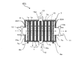
- FIG. 1 is a cross-sectional view schematically showing a regenerative water softening device according to Embodiment 1 of the present invention.
- FIG. 2A is a plan view schematically showing the main surface of the cathode.
- FIG. 2B is a plan view schematically showing the main surface of the anode.
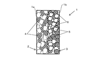
- FIG. 3 is a side view schematically showing a water-splitting porous ion exchange membrane.
- a regenerative water softening device (hereinafter referred to as “water softening device”) 201 is formed by a water-splitting porous ion exchange membrane (hereinafter referred to as “ion exchange membrane”) 1. It is an apparatus that removes cations of hardness components such as ions and magnesium ions (hereinafter referred to as “hardness component ions”) from the water for treatment, and softens the water for treatment.
- the water softening device 201 includes electrodes 8 and 9, an ion exchange membrane, and a casing 7 that houses the electrode and the ion exchange membrane 1.
- each electrode 8, 9 is a substantially rectangular flat plate, and has connection portions 8 a, 9 a and a large number of openings 224.
- the opening 224 penetrates the main surface of each electrode 8, 9.
- the size and number of the openings 224 are set so as not to obstruct the flow of processing water passing through the openings 224.
- Each electrode 8 and 9 is comprised with plate
- board materials such as a metal
- the metal titanium having corrosion resistance and mechanical durability is used.
- the protective layer platinum coating or the like is raised, and the thickness of the protective layer is, for example, 0.2 ⁇ m to 0.5 ⁇ m.
- the ion exchange membrane 1 has a cation exchange surface 1a on one surface and an anion exchange surface 1b on the other surface.
- the ion exchange membrane 1 is laminated between the cathode 8 and the anode 9 such that the anion exchange surface 1 b faces the anode 9 and the cation exchange surface 1 a faces the cathode 8.
- the ion exchange membrane 1 is formed by superposing and joining a cation exchange membrane 2 and an anion exchange membrane 3 in the thickness direction. For this reason, the cation exchange surface 1 a is formed on the surface of the cation exchange membrane 2, and the anion exchange surface 1 b is formed on the surface of the anion exchange membrane 3.
- the cation exchange membrane 2 is formed of a sintered body solidified by heating a mixture of the cation exchange resin particles 4 and the thermoplastic resin particles 5 in the vicinity of the melting point of the thermoplastic resin particles 5. For this reason, the cation exchange resin particles 4 are fixed in the matrix of the thermoplastic resin particles 5 so that a void is formed between the cation exchange resin particles 4 and the thermoplastic resin particles 5.
- the anion exchange membrane 3 is formed of a sintered body that is solidified by heating a mixture of the anion exchange resin particles 6 and the thermoplastic resin particles 5 in the vicinity of the melting point of the thermoplastic resin particles 5. For this reason, the anion exchange resin particles 6 are fixed in the matrix of the thermoplastic resin particles 5 so that a void is formed between the anion exchange resin particles 6 and the thermoplastic resin particles 5.
- the thermoplastic resin particles 5 are formed of, for example, a thermoplastic resin such as a polyolefin resin such as polyethylene and polypropylene, an ethylene-propylene copolymer, an ethylene-vinyl acetate copolymer, and an ethylene-acrylic acid copolymer.
- a thermoplastic resin such as a polyolefin resin such as polyethylene and polypropylene, an ethylene-propylene copolymer, an ethylene-vinyl acetate copolymer, and an ethylene-acrylic acid copolymer.
- the particle diameter of the thermoplastic resin particles 5 is set to several tens to several hundreds ⁇ m, for example. However, as the particle diameter of the thermoplastic resin particles 5 is smaller, the rate at which hardness component ions are adsorbed to the ion exchange membrane 1 is increased, and the efficiency of removing the hardness component ions is improved. However, the smaller the particle size of the thermoplastic resin particles 5, the greater the pressure loss when the treatment water passes through the ion exchange membrane 1. For this reason, the particle diameter of the thermoplastic resin particles 5 is set in consideration of the removal efficiency of hardness component ions and the pressure loss.
- the cation exchange resin particles 4 are formed of, for example, a strongly acidic cation exchange resin having an exchange group —SO 3 H.
- the anion exchange resin particles 6 are formed of, for example, a strongly basic ion exchange resin having an exchange group —NR 3 OH.
- the cation exchange resin particles 4 can also be formed from a weakly acidic cation exchange resin having an exchange group —RCOOH.
- the anion exchange resin particles 6 can be formed from a weakly basic ion exchange resin having —NR 2 .
- the content of the cation exchange resin particles 4 in the cation exchange membrane 2 and the content of the anion exchange resin particles 6 in the anion exchange membrane 3 are 10 to 60 wt% with respect to the weight of each ion exchange membrane 2 and 3. Thus, it is preferably 30 to 50 wt%.
- the content of each ion-exchange resin particle 4 or 6 is 60% or more, the amount of the thermoplastic resin particle 5 is reduced with respect to each ion-exchange resin particle 4 or 6. Is difficult to fix with the thermoplastic resin particles 5.
- the content of each ion exchange resin particle 4 or 6 is 10% or less, the capacity for exchanging ions in the unit volume of each ion exchange membrane 2 or 3 becomes small.
- each ion exchange membrane 2, 3 which leads to an increase in size and cost of the water softening device 201.
- the content of each of the ion exchange resin particles 4 and 6 is 30 to 50 wt%, the ion exchange capacity of the ion exchange membrane 1 can be maintained, and the ion exchange membrane 1 can be used stably over a long period of time. Can do.
- the casing 7 has a rectangular parallelepiped shape, and includes first to fourth side surfaces 7a to 7d, a first end surface, a second end surface, and a hollow portion surrounded by these.
- the second side surface 7b faces the first side surface 7a
- the fourth side surface 7d faces the third side surface 7c.
- the first and second side surfaces 7a and 7b are shorter than the third and fourth side surfaces 7c and 7d. For this reason, the space
- the casing 7 has a first inlet 10 and a first outlet 11 for water for treatment, and a second inlet 12 and a second outlet 13 for water for regeneration.
- the first inlet 10 and the second inlet 12 are each connected to piping (not shown) supplied from a water source such as a water pipe.
- the first outlet 11 is a faucet (not shown) that discharges the water for softening treatment, a water heater that uses the water for softening treatment, a hot water heating system, a washing machine, a water purification system, or the like (Not shown).
- the second outlet 13 is connected to a path (not shown) for discharging the regeneration water used for the regeneration process of the ion exchange membrane 1.
- a first inlet 10 into which the processing water flows is provided on the first side surface 7a, and a first outlet 11 through which the processing water flows out is provided on the second side surface 7b.
- a second inlet 12 through which the regeneration water flows is provided on the third side surface 7c, and a second outlet 13 through which the regeneration water flows out is provided on the fourth side surface 7d.
- the first inlet 10 and the first outlet are set so that the straight line connecting the first inlet 10 and the first outlet 11 of the treatment water and the straight line connecting the second inlet 12 and the second outlet 13 of the regeneration water are perpendicular to each other. 11, a second inlet 12 and a second outlet 13 are provided.
- the respective inlets 10 and 12 and the respective outlets 11 and 13 penetrate the respective side surfaces 7a to 7d.
- Solenoid valves 16a to 16d are provided at the first inlet 10, the first outlet 11, the second inlet 12, and the second outlet 13, respectively.
- a straight line connecting the first inlet 10 and the first outlet 11 of the processing water is formed by connecting the center of the first inlet 10 and the center of the first outlet 11.
- a straight line connecting the second inlet 12 and the second outlet 13 of the water for regeneration is formed by connecting the center of the second inlet 12 and the center of the second outlet 13.
- the first inlet 10 and the first outlet 11 are set so that the straight line connecting the first inlet 10 and the first outlet 11 of the treatment water and the straight line connecting the second inlet 12 and the second outlet 13 of the regeneration water are perpendicular to each other.
- a second inlet 12 and a second outlet 13 are provided, and the overall flow of treatment water from the first inlet 10 to the first outlet 11 is the overall flow of regeneration water from the second inlet 12 to the second outlet 13. Be perpendicular to the flow.
- the anode 9, the cathode 8, and one or more, in this embodiment, a laminate of seven ion exchange membranes 1 are accommodated.
- the anode 9, the cathode 8, and the ion exchange membrane 1 are arranged in parallel so that the cation exchange membrane 2 faces the cathode 8 and the anion exchange membrane 3 faces the anode 9.
- the ion exchange membrane 1 is provided perpendicular to a straight line connecting the first inlet 10 and the first outlet 11. For this reason, the flow path 14 of the processing water flowing in from the first inlet 10 and flowing out from the first outlet 11 extends in a direction orthogonal to the ion exchange membrane 1.
- the ion exchange membrane 1 Since the ion exchange membrane 1 is formed in substantially the same size as the longitudinal section of the hollow portion of the casing 7, the ion exchange membrane 1 is arranged so as to block the flow path 14 for the processing water.
- the ion exchange membrane 1 is provided in parallel to a straight line connecting the second inlet 12 and the second outlet 13. For this reason, the flow path 15 for regenerating water flowing in from the second inlet 12 and flowing out from the second outlet 13 extends along the ion exchange membrane 1.
- a gap is provided between the anode 9, the cathode 8, and the ion exchange membrane 1. This gap becomes a flow path 15 for water for regeneration.
- the treatment water channel 14 formed between the first inlet 10 and the first outlet 11 is longer than the regeneration water channel 15 formed between the second inlet 12 and the second outlet 13. For this reason, the differential pressure of the treatment water generated between the first inlet 10 and the first outlet 11 is greater than the differential pressure of the regeneration water generated between the second inlet 12 and the second outlet 13 at the same flow rate as the treatment water. growing.
- the casing 7 is further provided with an opening (not shown).
- the connecting portion 8a of the cathode 8 and the connecting portion 9a of the anode 9 protrude from the opening.
- a sealing material (not shown) is filled between the opening and each connection portion 8a, 9a, and the watertight performance of the casing 7 is maintained.
- Each connecting portion 8a, 9a is connected to a power source (not shown) by an electric wire (not shown), and a switch (not shown) is interposed in the electric wire.
- the treatment water flows from the first inlet 10, passes through the opening 224 of the cathode 8, and further passes through the ion exchange membrane 1. At this time, hardness component ions contained in the water for treatment are adsorbed on the cation exchange resin particles 4 of the cation exchange membrane 2. As a result, hardness component ions are removed from the treatment water, and the treatment water becomes soft water and is discharged from the first outlet 11.
- the flow rate of the treatment water is reduced by the drag. Moreover, since the treatment water receives resistance by the ion exchange membrane 1 when the treatment water passes through the ion exchange membrane 1, the flow rate of the treatment water further decreases. As a result, the time during which the treatment water stays in the casing 7 becomes long, and the treatment water comes into contact with the cation exchange resin particles 4 for a long time. Further, the treatment water passes through the cation exchange membrane 2 so that the treatment water also comes into contact with the cation exchange resin particles 4 inside the cation exchange membrane 2. Therefore, the hardness component ions in the water for treatment are adsorbed in contact with a large number of cation exchange resin particles 4 for a long time, thereby improving the adsorption efficiency of the hardness component ions.
- the adsorption efficiency of hardness component ions is high. As a result, it is not necessary to pass the hardness component ions through the ion exchange membrane 1 by applying a voltage to the electrodes 8 and 9 and moving the hardness component ions by electrophoresis. Therefore, electric power is not consumed in the water softening step, and overall power consumption is suppressed.
- the regeneration water in the casing 7 is electrolyzed at the interface between the cation exchange membrane 2 and the anion exchange membrane 3, and hydrogen ions are generated in the cation exchange membrane 2, and hydroxide ions Is generated in the anion exchange membrane 3.
- the electrolyzed hydrogen ions are replaced with the hardness component ions adsorbed on the cation exchange resin particles 4 of the cation exchange membrane 2.
- hardness component ions are removed from the cation exchange membrane 2, and the ion exchange membrane 1 is regenerated.
- the hardness component ions desorbed from the ion exchange membrane 1 are discharged from the second outlet 13 along with the flow through the regeneration water channel 15.
- the regeneration water channel 15 is parallel to the ion exchange membrane 1
- hardness component ions passing through the regeneration water channel 15 move along the surface of the ion exchange membrane 1.
- the hardness component is prevented from reattaching to the ion exchange membrane 1 without almost entering the inside of the ion exchange membrane 1, and the ion exchange membrane 1 is efficiently regenerated.
- hydrogen ions that replace hardness component ions attached to the ion exchange membrane 1 are generated at the interface between the cation exchange membrane 2 and the anion exchange membrane 3. Thereby, hardness component ions are removed from the inside of the ion exchange membrane 1 by hydrogen ions, and the entire ion exchange membrane 1 is regenerated.
- the regeneration water passage 15 is shorter than the treated raw water passage 14, the decrease in the regeneration water flow rate due to drag is small.
- the regeneration water passes along the surface of the ion exchange membrane 1, the resistance received from the ion exchange membrane 1 is small, and a decrease in the flow rate of the regeneration water is suppressed.
- the time for the regeneration water to stay in the casing 7 is short, and the time for the regeneration water to contact the cation exchange resin particles 4 is shortened.
- the regeneration water is along the surface of the cation exchange membrane 2, the cation exchange resin particles 4 inside the cation exchange membrane 2 and the treatment water hardly come into contact with each other. Therefore, the time and range in which the hardness component ions in the water for regeneration come into contact with the cation exchange resin particles 4 are short, and the hardness component ions are prevented from being re-adsorbed on the ion exchange membrane 1.
- the first inlet 10 and the first outlet 11 are opened, and the second inlet 12 and the second outlet 13 are closed.
- the treatment water flowing in from the first inlet 10 does not flow out of the second inlet 12 and the second outlet 13 but flows out of the first outlet 11.
- the process water flow path 14 extended from the 1st inlet 10 to the 1st outlet 11 is formed, and a water softening process is performed efficiently.
- the second inlet 12 and the second outlet 13 are opened, and the first inlet 10 and the first outlet 11 are closed.
- the regeneration water that has flowed in from the second inlet 12 does not flow out of the first inlet 10 and the first outlet 11 but flows out of the second outlet 13.
- the regeneration water flow path 15 extending from the second inlet 12 to the second outlet 13 is formed, and the regeneration process is performed efficiently.
- the ion exchange membrane 1 is provided perpendicular to the straight line connecting the first inlet 10 and the first outlet 11, that is, the processing water flow path 14.
- the ion exchange membrane 1 is provided in parallel to the straight line connecting the first inlet 10 and the first outlet 11, that is, to the treatment water flow path 14.
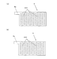
- FIG. 4A is a cross-sectional view schematically showing a water softening device according to Embodiment 2 of the present invention.
- FIG.4 (b) is a longitudinal cross-sectional view which shows typically the water softening apparatus of Fig.4 (a).
- the cathode 8 and the anode 9 are provided in parallel to the first end surface 7e and the second end surface 7f of the casing 7.
- the ion exchange membrane 1 is provided between the cathode 8 and the anode 9 such that the anion exchange membrane 3 faces the anode 9 and the cation exchange membrane 2 faces the cathode 8.
- the ion exchange membrane 1 has a rectangular shape including a long side 1a and a short side 1b. Each length of the long side 1a and the short side 1b is set based on the contact probability of hardness component ions to the ion exchange membrane 1.
- the ion exchange membrane 1 has a long side 1 a parallel to a straight line connecting the first inlet 10 and the first outlet 11, and a short side 1 a corresponding to a straight line connecting the second inlet 12 and the second outlet 13. Are provided in parallel. For this reason, the anode 9, the cathode 8, and one or more, in this embodiment, for example, two ion exchange membranes 1 are stacked in parallel with a gap therebetween.
- a treatment water channel 14 and a regeneration water channel 15 are formed in the gaps between the electrodes 8 and 9 and the ion exchange membrane 1 and in the gaps between adjacent ion exchange membranes 1.
- the treatment water flows along the ion exchange membrane 1, the treatment water does not enter the inside of the ion exchange membrane 1 compared to the case where the treatment water passes through the ion exchange membrane 1.
- the treatment water flow path 14 is long, the treatment water is in contact with the cation exchange resin particles 4 in the ion exchange membrane 1 for a long time. Therefore, the hardness component ions in the water for treatment are adsorbed by contacting with the cation exchange resin particles 4 for a long time, thereby improving the adsorption efficiency of the hardness component ions.
- the regeneration water flows along the ion exchange membrane 1, it is possible to prevent the desorbed hardness component ions from entering the ion exchange membrane 1 and reattaching.
- the regeneration water channel 15 is shorter than the treated raw water channel 14, the time for which the regeneration water is in contact with the cation exchange resin particles 4 is short, so that the hardness component ions are regenerated on the downstream side of the ion exchange membrane 1. Adsorption is prevented.
- hydrogen ions are generated at the interface between the cation exchange membrane 2 and the anion exchange membrane 3, the hardness component ions are totally removed from the inside of the ion exchange membrane 1, and the entire ion exchange membrane 1 is regenerated.
- the first inlet 10, the first outlet 11, the second inlet 12, and the second outlet 13 are provided one by one.
- a plurality of first inlets 10, first outlets 11, second inlets 12, and second outlets 13 are provided in the water softening device 201 of the third embodiment.
- the water softening device 201 of the third embodiment further includes a diffusion layer 218, a spacer member 217, and a sealing material 219.
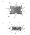
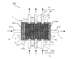
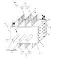
- FIG. 5 is a perspective view schematically showing a water softening device according to Embodiment 3 of the present invention.
- FIG. 6 is a longitudinal sectional view showing the water softening device cut along the line BB shown in FIG.
- FIG. 7 is a cross-sectional view showing the water softening device 201 cut along the line CC shown in FIG.
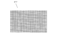
- FIG. 8 is a plan view schematically showing a spacer member used in the water softening device of FIG.
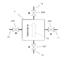
- FIG. 9 is a conceptual diagram showing the flow of processing water in the water softening step.
- FIG. 10 is a conceptual diagram showing the flow of water for regeneration in the regeneration process.
- a first inlet 10, a first outlet 11, a second inlet 12, and a second outlet 13 are provided in the casing 7.
- the first inlet 10 for example, three pipes 213 are connected to the first side surface 7a. These pipes 213 are collected into one main pipe (not shown) provided with an electromagnetic valve 225 (FIGS. 9 and 10).
- the first outlet 11 for example, three pipes 215 (FIG. 6) are connected to the second side surface 7b. These pipes 215 are collected into one main pipe (not shown) provided with an electromagnetic valve 226 (FIGS. 9 and 10).
- the second inlet 12 for example, nine pipes 220 are connected to the third side surface 7c.
- the casing 7 accommodates therein a pair of electrodes 8 and 9 and a laminated body in which a plurality of, in this embodiment, 10 ion exchange membranes 1 are laminated.
- the ion exchange membrane 1 is disposed between the anode 9 and the cathode 8 such that the cation exchange membrane 210 faces in parallel with the cathode 8 and the anion exchange membrane 211 faces in parallel with the anode 9.
- the ion exchange membrane 1 is formed by joining the cation exchange membrane 210 and the anion exchange membrane 211 so as to overlap each other in the thickness direction.
- the cation exchange membrane 210 is the same as the cation exchange membrane 2 shown in FIG. 3, and the anion exchange membrane 211 is the same as the anion exchange membrane 3 shown in FIG.
- the spacer member 217 is provided so as to sandwich the ion exchange membrane 1 in order to secure a flow path for flowing regeneration water between the adjacent ion exchange membranes 1 in the laminate.
- the spacer member 217 may be disposed between the anode 9 and the ion exchange membrane 1 and between the cathode 8 and the ion exchange membrane 1.
- As the spacer member 217 a plate-like body having a large number of through holes, for example, a mesh-like mesh sheet shown in FIG. 8 is used, and the size thereof is set to the same size as the surface of the ion exchange membrane 1, for example. .
- the spacer member 217 is formed of, for example, a fluororesin ETFE having water resistance and mechanical durability.
- the diffusion layer 218 is a layer that diffuses the processing water flowing from the first inlet 10 in a direction perpendicular to the processing water flow path 14.
- the diffusion layer 218 is formed from a resin having water resistance and mechanical durability, such as polyethylene and high-density polyethylene.
- the diffusion layer 218 is formed of, for example, a porous sheet that has a greater water resistance than the ion exchange membrane 1.
- the diffusion layer 218 is provided between the laminate of the ion exchange membrane 1 and the electrode on the first inlet 10 side, in this embodiment, the anode 9.
- the diffusion layer 218 is disposed perpendicular to the treatment water flow path 14 and parallel to the ion exchange membrane 1.
- the sealing material 219 is a non-water-permeable member that covers the periphery of the laminate of the ion exchange membrane 1 as shown in FIGS. 6 and 7.
- the sealing material 219 is filled between the end surface of the ion exchange membrane 1 and the inner surfaces 7c, 7d, 7e, and 7f of the casing 7, and prevents treatment water from passing therethrough.
- the end surface of the ion exchange membrane 1 is a surface that is perpendicular to the bonding surface of the ion exchange membrane 1 and is arranged in parallel with the treatment water flow path 14.
- the sealing material 219 is formed of, for example, a silicone resin having water permeability and water resistance.
- the sealing material 219 has a plurality of openings 222 and 223 on the side surfaces 7c and 7d of the casing 7, respectively.
- the plurality of openings 222 and 223 penetrate in the thickness direction of the sealing material 219.
- the number of the openings 222 is arranged so that the number thereof matches the number of the pipes 220 of the second inlet 12, and the positions thereof face the pipes 220 and the spacer member 217. For this reason, the regeneration water that has flowed from the pipe 220 flows into the regeneration water flow path 15 formed in the spacer member 217.
- the number of openings 223 is arranged so that the number thereof matches the number of pipes 221 of the second outlet 13 and the positions thereof face the pipes 221 and the spacer member 217, respectively. Therefore, the regeneration water that has passed through the regeneration water passage 15 in the spacer member 217 is discharged from the pipe 221.
- the treatment water flows uniformly from the entire diffusion layer 218 to the entire surface of the ion exchange membrane 1.
- the treatment water passes through the through holes of the spacer member 217 and the ion exchange membrane 1.
- the treatment water has a large resistance to pass through the inside of the ion exchange membrane 1, but the treatment water has passed through the ion exchange membrane 1 because the periphery of the laminate of the ion exchange membrane 1 is covered with the sealing material 219. pass.
- hardness component ions contained in the treatment water are adsorbed on the cation exchange membrane 210 of the ion exchange membrane 1, and the treatment water is softened.
- the treatment water passes through the laminated body of the ion exchange membrane 1 and then flows out through the opening 224 of the cathode 8 to the pipe 215 of the first outlet 11.
- the regeneration water flows along the ion exchange membrane 1 through the regeneration water channel 15 in the spacer member 217.
- a voltage of 100 V to 300 V is applied to each electrode 8, 9, so that the water for regeneration is hydrogen ion and water at the interface between the cation exchange membrane 210 and the anion exchange membrane 211 in the ion exchange membrane 1.
- the hydrogen ions are replaced with hardness component ions adsorbed on the cation exchange membrane 210, and the ion exchange membrane 1 is regenerated.
- the hardness component ions are desorbed from the cation exchange membrane 210 and discharged from the pipe 221 of the second outlet 13 through the opening 223 along with the regeneration water.
- the non-water-permeable sealing material 219 prevents the treatment water from flowing between the casing 7 and the ion exchange membrane 1. Thereby, it is suppressed that the quantity of the process water which passes the ion exchange membrane 1 reduces. Therefore, the contact probability between the cation exchange resin particles 4 of the cation exchange membrane 210 of the ion exchange membrane 1 and the hardness component ions is increased, and the hardness component ions are efficiently adsorbed to the cation exchange resin particles 4, so that The efficiency of water softening can be increased.
- the opening portions 222 and 223 of the sealing material 219 face the pipes 220 and 221 and the spacer member 217, respectively. For this reason, the regeneration water that has flowed in from the pipe 220 passes smoothly through the opening 222 into the regeneration water flow path 15 in the spacer member 217. Therefore, the hardness component ions desorbed from the ion exchange membrane 1 are almost parallel to the ion exchange membrane 1 while spreading along the surface of the ion exchange membrane 1 without almost entering the inside of the ion exchange membrane 1 by the regeneration water. Flowing. Therefore, hardness component ions can be prevented from adsorbing to the cation exchange resin particles 4, and the regeneration efficiency is increased.
- the spacer member 217 is disposed between the ion exchange membranes 1 adjacent to each other in the laminate, and forms a regeneration water flow path 15 extending in parallel with the ion exchange membrane 1. For this reason, the regeneration water flows smoothly in parallel with the ion exchange membrane 1, and the area and time for contacting the hardness component ions desorbed in the regeneration water with the ion exchange membrane 1 are reduced. Therefore, resorption of hardness component ions to the ion exchange membrane 1 is suppressed, and the regeneration efficiency of the ion exchange membrane 1 is improved.
- the diffusion layer 218 is disposed between the electrode 9 on the first inlet 10 side and the laminate of the ion exchange membrane 1.
- the treatment water flowing from the first inlet 10 is directed to the ion exchange membrane 1 while spreading in a direction perpendicular to the treatment water flow path 14. Therefore, the treatment water passes through the ion exchange membrane 1 as a whole, and hardness component ions contained in the treatment water are adsorbed in a wide range of the ion exchange membrane 1. Accordingly, the water softening performance of the treatment water is further improved.
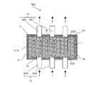
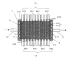
- FIG. 11 is a perspective view schematically showing a water softening device according to Embodiment 4 of the present invention.
- 12 is a longitudinal sectional view showing the water softening device cut along the line DD shown in FIG.
- the number of the pipe 220 at the second inlet 12, the pipe 221 at the second outlet 13, the spacer member 217, and the openings 222 and 223 of the sealing material 219 are equal.
- the opening 222 of the sealing material 219 faces the piping 220 and the spacer member 217 on a one-to-one basis
- the opening 223 faces the piping 221 and the spacer member 217 on a one-to-one basis.
- the pipe 220 at the second inlet 12 and the pipe 221 at the second outlet 13 penetrate the sealing material 219 through the openings 222 and 223.
- the pipe 220 at the second inlet 12 and the pipe 221 at the second outlet 13 are in contact with the space in which the spacer member 217 is disposed.
- the water for regeneration flows from the pipe 220 of the second inlet 12 through the opening 222 into the space member facing it. Then, the regeneration water flows into the regeneration water flow path 15 in the space member facing the opening 222 without branching to the regeneration water flow path 15 in the plurality of space members. Further, the regeneration water that has passed through the regeneration water flow path 15 flows out from the pipe 221 through the opening 223 that faces the space member. For this reason, the regeneration water passes smoothly through the regeneration water flow path 15 along the ion exchange membrane 1. As a result, the hardness component ions contained in the water for regeneration are reduced in time and range in contact with the ion exchange membrane 1 and are prevented from being re-adsorbed on the ion exchange membrane 1. As a result, the regeneration efficiency of the ion exchange membrane 1 by the regeneration water in the entire water softening device 201 is further improved.
- a DC voltage of, for example, 100 V to 300 V is applied between the electrodes 9 and 8 in the regeneration process.
- the value of the DC voltage is appropriately set according to the number of ion exchange membranes 1 disposed in the casing 7 and the hardness of the water for treatment.
- the electrodes 8 and 9 having the openings 224 are used, but electrodes having no openings may be used.
- the treatment water passes around the electrodes 8 and 9 in the first, third, and fourth embodiments, and passes between the electrodes 8 and 9 in the second embodiment.
- the ion exchange membrane 1 was formed by joining the cation exchange membrane 2 and the anion exchange membrane 3.
- an ion exchange membrane can also be formed by arranging the cation exchange membrane 2 and the anion exchange membrane 3 so as not to be joined.
- the cation exchange surface 1a is the surface of the cation exchange membrane 2.
- the anion exchange surface 1b was formed on the surface of the anion exchange membrane 3.
- the formation method of the cation exchange surface 1a and the anion exchange surface 1b is not limited to this.
- the cation exchange surface 1a may be formed on one surface of one ion exchange membrane, and the anion exchange surface 1b may be formed on the other surface.
- the water softening device 201 of the first, third, and fourth embodiments since the water for treatment is passed in the direction perpendicular to the ion exchange membrane 1 in the water softening step, the water-splitting porous ion exchange membrane having water permeability is used. 1 was used for the ion exchange membrane 1. However, when treatment water flows parallel to the surface of the ion exchange membrane 1 as in the second embodiment, the ion exchange membrane 1 having water permeability may not be used.
- both the diffusion layer 218 and the sealing material 219 are provided.
- only the sealing material 219 may be provided.
- At least one of the spacer member 217, the diffusion layer 218, and the sealing material 219 may be further provided.
- a spacer member 217 may be further provided.
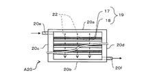
- FIG. 13 is a cross-sectional view schematically showing the first water softening evaluation device.
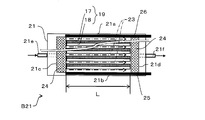
- FIG. 14 is a cross-sectional view schematically showing the second water softening evaluation apparatus.
- Example 1 Using the first water softening evaluation device A20 of FIG. 13 and the second water softening evaluation device B21 of FIG. 14, the water softening ability (hardness component ion removal ability) according to the direction of water flow with respect to the ion exchange membrane 1 was evaluated.
- a cation exchange membrane 17 was prepared using cation exchange resin particles of 100 to 150 ⁇ m and polyethylene resin particles as thermoplastic resin particles of several tens to several hundreds of ⁇ m.
- An anion exchange membrane 18 was prepared using anion exchange resin particles of 100 to 150 ⁇ m and polyethylene resin particles as thermoplastic resin particles of several tens to several 100 ⁇ m.
- the thickness of each ion exchange membrane 17, 18 is 1 mm.
- These cation exchange membrane 17 and anion exchange membrane 18 were bonded together to form an ion exchange membrane 19.
- the ion exchange membrane 19 had a thickness of 2 mm, a short side of 4 cm, and a long side of 10 cm.
- the 1st water softening evaluation apparatus A20 is an apparatus which evaluates water softening by the decreasing rate of the hardness component ion contained in water, when water is flowed perpendicularly with respect to the ion exchange membrane 1.
- the first water softening evaluation apparatus A20 includes first and second long sides 20a and 20b, first and second short sides 20c and 20d, an inlet 20e, and an outlet 20f.
- the inflow port 20e is disposed on the first short side 20c on the first long side 20a side
- the outflow port 20f is disposed on the second short side 20d on the second long side 20b side.
- the water flow path 22 in the first water softening evaluation device A20 is perpendicular to the long sides 20a and 20b from the first long side 20a side to the second long side 20b side, and each short side. The flow is parallel to 20c and 20d.
- the first water softening evaluation apparatus A20 a plurality of laminated bodies in which, for example, seven ion exchange membranes 19 are laminated are accommodated in this embodiment.
- the water flow distance of the flow path 22, that is, the length between the first long side 20a and the second long side 20b is about 14 mm, for example.
- Each ion exchange membrane 19 is arranged such that the cation exchange membrane 17 faces the first long side 20a in parallel and the anion exchange membrane 18 faces the second long side 20b in parallel.
- the ion exchange membrane 19 has a long side parallel to the long sides 20a and 20b, and is provided at an equal interval. For this reason, the ion exchange membrane 19 is arranged perpendicular to the flow of water.
- the long side of the ion exchange membrane 1 is between the first short side 20c and the second short side 20d. Fit in between.
- the gap may be filled with an adhesive, a leak-proof packing, or the like so that no gap is generated between the ion exchange membrane 19 and each of the short sides 20c and 20d.
- an adhesive or the like is disposed so that the flow of water from the inlet 20e to the outlet 20f is not hindered.
- the 2nd water softening evaluation apparatus B21 is an apparatus which evaluates water softening by the decreasing rate of the hardness component ion contained in water, when water is flowed in parallel with respect to the ion exchange membrane 1.
- the second water softening evaluation apparatus B21 includes first and second long sides 21a and 21b, first and second short sides 21c and 21d, an inlet 21e, and an outlet 21f.
- the inflow port 21e is disposed on the first short side 21c
- the outflow port 21f is disposed on the second short side 21d.
- the inflow port 21e and the outflow port 21f are disposed so as to face each other between the first long side 21a and the second long side 21b.
- the water flow path 23 in the second water softening evaluation apparatus B21 is parallel to the long sides 20a and 20b from the first short side 21c side to the second short side 21d side, and each short side 20c. , 20d.
- the water flow distance of the flow path 23, that is, the length between the first short side 21c and the second short side 21d is, for example, 10 cm.
- each ion exchange membrane 19 is arranged such that the cation exchange membrane 17 faces the first long side 21a in parallel and the anion exchange membrane 18 faces the second long side 21b in parallel.
- each ion exchange membrane 19 has a long side parallel to the long sides 21a and 21b and is provided at equal intervals. For this reason, the ion exchange membrane 19 is arranged in parallel to the flow of water.
- the long side of the ion exchange membrane 19 is between the first short side 21c and the second short side 21d. Fit in between.
- the gap may be filled with an adhesive, a leak-proof packing, or the like so that no gap is generated between the ion exchange membrane 19 and each of the short sides 21c and 21d.
- an adhesive or the like is arranged so that the flow of water from the inlet 21e to the outlet 21f is not hindered.
- the rectifying plate 24 is provided between the first short side 21c and the laminate of the ion exchange membrane 19 and the second short side 21d. And the laminated body of the ion exchange membranes 19.
- the concentration of hardness component ions of water flowing in from the inlets 20e and 21e was adjusted to about 190 ppm in terms of calcium carbonate (CaCO3).
- This water is, for example, 0.42 L / min. Flowed in from the inlets 20e and 21e. And water passes the flow paths 22 and 23, and flows out from the outflow ports 20f and 21f. Calcium ions contained in water at the outlets 20f and 21f were measured. And the calcium removal capacity
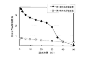
- FIG. 15 is a graph showing the relationship between calcium removal ability (water softening ability) and running time.
- the vertical axis represents the calcium removal ability in which the difference between the hardness component ion concentration at the inlets 20e and 21e and the hardness component ion concentration at the outlets 20f and 21f is normalized by a predetermined value.
- the calcium removal ability (water softening ability) of the first water softening evaluation device A20 is about 3 to 4 times as large as the calcium removal ability (water softening ability) of the second water softening evaluation device B21. From this result, when water passes perpendicularly to the ion exchange membrane 19 as in the first water softening evaluation apparatus A20, the water exchange membrane 19 efficiently adsorbs calcium ions contained in water, and the water is softened. It can be seen that
- Example 2 Regeneration capability of ion exchange membrane 1 of water softening device 201 (ability to desorb hardness component ions from ion exchange membrane 1) according to the length of the flow path using second water softening evaluation device B21 of FIG. was evaluated.
- an anode 25 and a cathode 26 are accommodated in the second water softening evaluation apparatus B21.
- a laminate of the ion exchange membrane 19 is sandwiched between the anode 25 and the cathode 26 such that the anode 25 faces the anion exchange membrane 18 in parallel and the cathode 26 faces the cation exchange membrane 17 in parallel.
- a voltage of 100 V is applied to the anode 25 and the cathode 26.
- about 50 ppm of water in terms of calcium carbonate (CaCO3) is 0.42 L / min.
- the concentration of calcium ions contained in the water at the outlet 21f was measured.
- the calcium desorption capacity in the channel 23 having a length of 10 cm (regeneration capacity of the ion exchange membrane 1).
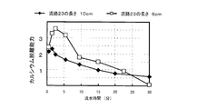
- FIG. 16 is a graph showing the relationship between calcium desorption capacity (regeneration capacity of the ion exchange membrane 1) and running water time.
- the vertical axis indicates the calcium desorption ability obtained by standardizing the difference between the hardness component ion concentration at the inlet 21e and the hardness component ion concentration at the outlet 21f with a predetermined value.
- the calcium desorption ability (regeneration ability of the ion exchange membrane 1) when the length of the flow path 23 is 10 cm is smaller than that when the length of the flow path 23 is 6 cm.
- the water softening device of the present invention is useful as a water softening device or the like that suppresses power consumption as compared with the prior art.
Landscapes
- Chemical & Material Sciences (AREA)
- Chemical Kinetics & Catalysis (AREA)
- Organic Chemistry (AREA)
- Life Sciences & Earth Sciences (AREA)
- Engineering & Computer Science (AREA)
- Molecular Biology (AREA)
- Electrochemistry (AREA)
- General Chemical & Material Sciences (AREA)
- Hydrology & Water Resources (AREA)
- Analytical Chemistry (AREA)
- Environmental & Geological Engineering (AREA)
- Water Supply & Treatment (AREA)
- Health & Medical Sciences (AREA)
- Treatment Of Water By Ion Exchange (AREA)
- Water Treatment By Electricity Or Magnetism (AREA)
- Separation Using Semi-Permeable Membranes (AREA)
Abstract
Ce dispositif adoucisseur d'eau (201) comprend : une électrode négative (8) et une électrode positive (9) ; au moins une membrane de dissociation d'eau de type échangeuse d'ions (1) ayant une surface d'échange d'ions positifs (1a) sur une de ses faces, une surface d'échange d'ions négatifs (1b) sur son autre face, et se trouve entre l'électrode négative et l'électrode positive de façon que la surface d'échange d'ions négatifs soit en regard de l'électrode positive et que la surface d'échange d'ions positifs soit en regard de l'électrode négative ; et un boîtier (7) qui renferme l'électrode négative, l'électrode positive, et ladite au moins membrane de dissociation d'eau de type échangeuse d'ions. Le boîtier comporte : une première entrée (10) et une première sortie (11) qui sont respectivement l'entrée et la sortie de l'eau à traiter ; et une seconde entrée (12) et une seconde sortie (13) qui sont respectivement l'entrée et la sortie de l'eau à régénérer. La pression différentielle de l'eau à traiter entre la première entrée et la première sortie est supérieure à la pression différentielle de l'eau à régénérer entre la seconde entrée et la seconde sortie à un débit égal à celui de l'eau à traiter.
Priority Applications (3)
| Application Number | Priority Date | Filing Date | Title |
|---|---|---|---|
| JP2013514985A JP5935079B2 (ja) | 2011-05-13 | 2012-05-11 | 再生式軟水化装置 |
| EP12785473.5A EP2708514B8 (fr) | 2011-05-13 | 2012-05-11 | Appareil déminéralisant régénérateur |
| CN201280019301.8A CN103502155B (zh) | 2011-05-13 | 2012-05-11 | 再生式软水化装置 |
Applications Claiming Priority (4)
| Application Number | Priority Date | Filing Date | Title |
|---|---|---|---|
| JP2011-108011 | 2011-05-13 | ||
| JP2011108011 | 2011-05-13 | ||
| JP2011108013 | 2011-05-13 | ||
| JP2011-108013 | 2011-05-13 |
Publications (1)
| Publication Number | Publication Date |
|---|---|
| WO2012157236A1 true WO2012157236A1 (fr) | 2012-11-22 |
Family
ID=47176588
Family Applications (1)
| Application Number | Title | Priority Date | Filing Date |
|---|---|---|---|
| PCT/JP2012/003105 Ceased WO2012157236A1 (fr) | 2011-05-13 | 2012-05-11 | Dispositif adoucisseur d'eau par régénération |
Country Status (4)
| Country | Link |
|---|---|
| EP (1) | EP2708514B8 (fr) |
| JP (1) | JP5935079B2 (fr) |
| CN (1) | CN103502155B (fr) |
| WO (1) | WO2012157236A1 (fr) |
Cited By (7)
| Publication number | Priority date | Publication date | Assignee | Title |
|---|---|---|---|---|
| CN103253746A (zh) * | 2013-05-21 | 2013-08-21 | 浙江斯科能科技股份有限公司 | 浓水分流设计的防结垢电除盐器及其电除盐方法 |
| WO2014091726A1 (fr) * | 2012-12-14 | 2014-06-19 | パナソニック株式会社 | Échangeur d'ions, dispositif de traitement d'eau doté de celui-ci et dispositif d'alimentation en eau chaude |
| JP2015029920A (ja) * | 2013-07-31 | 2015-02-16 | パナソニック株式会社 | 水処理装置およびそれを備えた給湯装置 |
| WO2015162844A1 (fr) * | 2014-04-24 | 2015-10-29 | パナソニックIpマネジメント株式会社 | Membrane d'échange d'ions, corps stratifié de membrane d'échange d'ions pourvu d'une membrane d'échange d'ions, cellule électrochimique pourvue d'un corps stratifié de membrane d'échange d'ions et appareil de traitement de l'eau pourvu de la cellule électrochimique |
| WO2018008235A1 (fr) * | 2016-07-07 | 2018-01-11 | パナソニックIpマネジメント株式会社 | Dispositif de traitement de l'eau |
| US20220274100A1 (en) * | 2019-08-02 | 2022-09-01 | Panasonic Intellectual Property Management Co., Ltd. | Water softener |
| US20240317613A1 (en) * | 2022-01-20 | 2024-09-26 | Jiangxi Xinyuan New Material Technology Co., Ltd. | Electrolytic module units and water treatment systems based on boron-doped diamond (bdd) electrodes |
Families Citing this family (5)
| Publication number | Priority date | Publication date | Assignee | Title |
|---|---|---|---|---|
| EP2620216B1 (fr) * | 2010-09-21 | 2018-08-29 | Panasonic Corporation | Échangeur d'ions poreux, dispositif de traitement d'eau, dispositif d'alimentation en eau chaude, et procédé de fabrication d'un échangeur d'ions poreux |
| US10662082B2 (en) | 2014-10-03 | 2020-05-26 | The Regents Of The University Of California | Devices and methods for removing dissolved ions from water using composite resin electrodes |
| CN107250050A (zh) * | 2014-10-03 | 2017-10-13 | 加州大学校务委员会 | 使用复合树脂电极从水中除去溶解离子的设备和方法 |
| KR102200926B1 (ko) * | 2020-04-21 | 2021-01-11 | 한국해양과학기술원 | 심해저 채광 잔재물 정화처리 시스템 및 방법 |
| CN115581425B (zh) * | 2022-09-30 | 2025-01-28 | 宁波方太厨具有限公司 | 一种软水器及清洗机 |
Citations (5)
| Publication number | Priority date | Publication date | Assignee | Title |
|---|---|---|---|---|
| JP2001509074A (ja) * | 1997-01-28 | 2001-07-10 | パイオネティクス コーポレイション | 電気化学を利用するイオン交換 |
| JP2007501702A (ja) * | 2003-08-08 | 2007-02-01 | パイオネティックス, インコーポレイテッド | 電解イオン交換を伴う選択可能なイオン濃度 |
| JP2009233556A (ja) * | 2008-03-26 | 2009-10-15 | Panasonic Electric Works Co Ltd | イオン交換樹脂の再生方法 |
| JP2010069408A (ja) * | 2008-09-18 | 2010-04-02 | Panasonic Corp | 軟水化装置およびそれを備えた給湯装置 |
| JP2010201346A (ja) * | 2009-03-04 | 2010-09-16 | Panasonic Corp | 軟水化装置及びそれを用いた給湯機 |
Family Cites Families (10)
| Publication number | Priority date | Publication date | Assignee | Title |
|---|---|---|---|---|
| GB702316A (en) * | 1951-06-19 | 1954-01-13 | Tno | Process and apparatus for desalting liquids by means of ion-exchangers, and for regenerating said exchangers |
| US4032452A (en) * | 1975-11-13 | 1977-06-28 | Sybron Corporation | Electrically regenerated ion exchange system |
| ITTO20010847A1 (it) * | 2001-09-05 | 2003-03-05 | Eltek Spa | Apparato domestico con dispositivo elettrochimico di trattamento di un liquido, in particolare per l'addolcimento di acqua, e relativo metod |
| JP3794354B2 (ja) * | 2002-07-08 | 2006-07-05 | 栗田工業株式会社 | 電気脱イオン装置 |
| US7959780B2 (en) * | 2004-07-26 | 2011-06-14 | Emporia Capital Funding Llc | Textured ion exchange membranes |
| WO2009051612A1 (fr) * | 2007-10-18 | 2009-04-23 | Kinetico Incorporated | Appareil d'électrogénération et procédé de traitement de l'eau |
| WO2009077992A2 (fr) * | 2007-12-17 | 2009-06-25 | Ben Gurion University Of The Negev Research & Development Authority | Appareil et système de désionisation |
| CN201148367Y (zh) * | 2008-01-11 | 2008-11-12 | 孟广祯 | 电软化装置 |
| KR20090093323A (ko) * | 2008-02-29 | 2009-09-02 | 삼성전자주식회사 | 탈이온화 장치 및 그 제조방법 |
| JP4868006B2 (ja) * | 2009-02-24 | 2012-02-01 | パナソニック株式会社 | 洗濯機 |
-
2012
- 2012-05-11 JP JP2013514985A patent/JP5935079B2/ja not_active Expired - Fee Related
- 2012-05-11 EP EP12785473.5A patent/EP2708514B8/fr not_active Not-in-force
- 2012-05-11 CN CN201280019301.8A patent/CN103502155B/zh not_active Expired - Fee Related
- 2012-05-11 WO PCT/JP2012/003105 patent/WO2012157236A1/fr not_active Ceased
Patent Citations (6)
| Publication number | Priority date | Publication date | Assignee | Title |
|---|---|---|---|---|
| JP2001509074A (ja) * | 1997-01-28 | 2001-07-10 | パイオネティクス コーポレイション | 電気化学を利用するイオン交換 |
| JP4044148B2 (ja) | 1997-01-28 | 2008-02-06 | パイオネティクス コーポレイション | 電気化学を利用するイオン交換 |
| JP2007501702A (ja) * | 2003-08-08 | 2007-02-01 | パイオネティックス, インコーポレイテッド | 電解イオン交換を伴う選択可能なイオン濃度 |
| JP2009233556A (ja) * | 2008-03-26 | 2009-10-15 | Panasonic Electric Works Co Ltd | イオン交換樹脂の再生方法 |
| JP2010069408A (ja) * | 2008-09-18 | 2010-04-02 | Panasonic Corp | 軟水化装置およびそれを備えた給湯装置 |
| JP2010201346A (ja) * | 2009-03-04 | 2010-09-16 | Panasonic Corp | 軟水化装置及びそれを用いた給湯機 |
Cited By (14)
| Publication number | Priority date | Publication date | Assignee | Title |
|---|---|---|---|---|
| WO2014091726A1 (fr) * | 2012-12-14 | 2014-06-19 | パナソニック株式会社 | Échangeur d'ions, dispositif de traitement d'eau doté de celui-ci et dispositif d'alimentation en eau chaude |
| JP2014133228A (ja) * | 2012-12-14 | 2014-07-24 | Panasonic Corp | イオン交換体及びそれを備えた水処理装置、及び、給湯装置 |
| US9701547B2 (en) | 2012-12-14 | 2017-07-11 | Panasonic Intellectual Property Management Co., Ltd. | Ion exchanger, water treatment device provided with same, and hot water supply device |
| CN103253746A (zh) * | 2013-05-21 | 2013-08-21 | 浙江斯科能科技股份有限公司 | 浓水分流设计的防结垢电除盐器及其电除盐方法 |
| CN103253746B (zh) * | 2013-05-21 | 2015-06-17 | 浙江斯科能科技股份有限公司 | 浓水分流设计的防结垢电除盐器及其电除盐方法 |
| JP2015029920A (ja) * | 2013-07-31 | 2015-02-16 | パナソニック株式会社 | 水処理装置およびそれを備えた給湯装置 |
| JP2016000391A (ja) * | 2014-04-24 | 2016-01-07 | パナソニックIpマネジメント株式会社 | イオン交換膜、前記イオン交換膜を備えるイオン交換膜積層体、前記イオン交換膜積層体を備える電気化学セル、及び前記電気化学セルを備える水処理装置 |
| CN106029230A (zh) * | 2014-04-24 | 2016-10-12 | 松下知识产权经营株式会社 | 离子交换膜、具备离子交换膜的离子交换膜叠层体、具备离子交换膜叠层体的电化学单元、和具备电化学单元的水处理装置 |
| WO2015162844A1 (fr) * | 2014-04-24 | 2015-10-29 | パナソニックIpマネジメント株式会社 | Membrane d'échange d'ions, corps stratifié de membrane d'échange d'ions pourvu d'une membrane d'échange d'ions, cellule électrochimique pourvue d'un corps stratifié de membrane d'échange d'ions et appareil de traitement de l'eau pourvu de la cellule électrochimique |
| US10392273B2 (en) | 2014-04-24 | 2019-08-27 | Panasonic Intellectual Property Management Co., Ltd. | Ion exchange membrane, ion exchange membrane laminated body provided with ion exchange membrane, electrochemical cell provided with ion exchange membrane laminated body, and water treatment apparatus provided with electrochemical cell |
| WO2018008235A1 (fr) * | 2016-07-07 | 2018-01-11 | パナソニックIpマネジメント株式会社 | Dispositif de traitement de l'eau |
| US20220274100A1 (en) * | 2019-08-02 | 2022-09-01 | Panasonic Intellectual Property Management Co., Ltd. | Water softener |
| US20240317613A1 (en) * | 2022-01-20 | 2024-09-26 | Jiangxi Xinyuan New Material Technology Co., Ltd. | Electrolytic module units and water treatment systems based on boron-doped diamond (bdd) electrodes |
| US12195367B2 (en) * | 2022-01-20 | 2025-01-14 | Jiangxi Xinyuan New Material Technology Co., Ltd. | Electrolytic module units and water treatment systems based on boron-doped diamond (BDD) electrodes |
Also Published As
| Publication number | Publication date |
|---|---|
| EP2708514A4 (fr) | 2014-06-04 |
| CN103502155B (zh) | 2015-12-23 |
| EP2708514A1 (fr) | 2014-03-19 |
| EP2708514B1 (fr) | 2018-09-12 |
| EP2708514B8 (fr) | 2018-11-07 |
| CN103502155A (zh) | 2014-01-08 |
| JPWO2012157236A1 (ja) | 2014-07-31 |
| JP5935079B2 (ja) | 2016-06-15 |
Similar Documents
| Publication | Publication Date | Title |
|---|---|---|
| JP5935079B2 (ja) | 再生式軟水化装置 | |
| CN104520001B (zh) | 离子交换体和具备其的水处理装置、以及供热水装置 | |
| JP4913212B2 (ja) | 電気脱イオンシステムにおける電流分布をシフトする方法及び装置 | |
| JP6455775B2 (ja) | イオン交換膜、前記イオン交換膜を備えるイオン交換膜積層体、前記イオン交換膜積層体を備える電気化学セル、及び前記電気化学セルを備える水処理装置 | |
| CN103118783B (zh) | 多孔质离子交换体、水处理装置、供热水装置和多孔质离子交换体的制造方法 | |
| WO1999020567A1 (fr) | Appareil permettant de produire electriquement de l'eau desionisee | |
| JP2012236171A (ja) | 軟水化装置 | |
| CN111615497B (zh) | 用于生产去离子水的电去离子装置 | |
| CN101880074A (zh) | 一种失效离子交换树脂的电再生装置 | |
| JP5940387B2 (ja) | 電気式脱イオン水製造装置および脱イオン水製造方法 | |
| JP2011088085A (ja) | 電気式脱イオン水製造装置 | |
| JP2010201346A (ja) | 軟水化装置及びそれを用いた給湯機 | |
| US10507429B2 (en) | Electrochemical cell, water treatment device provided with same, and operating method for water treatment device | |
| JP2018176051A (ja) | イオン交換膜およびそれを備えたイオン交換膜積層体、水処理装置 | |
| JP2012081373A (ja) | 軟水化装置及びそれを備えた給湯機 | |
| JP2012236172A (ja) | 再生式軟水化装置 | |
| JP6167298B2 (ja) | 水処理装置およびそれを備えた給湯装置 | |
| KR20220148506A (ko) | 수 처리 장치용 필터 | |
| KR102528672B1 (ko) | 수 처리 장치용 필터 | |
| KR102341495B1 (ko) | 처리수와 농축수의 배출 경로 분리에 의해 회수율이 향상된 cdi장치 | |
| KR20170036442A (ko) | 전기 흡착식 수처리 장치용 셀 |
Legal Events
| Date | Code | Title | Description |
|---|---|---|---|
| 121 | Ep: the epo has been informed by wipo that ep was designated in this application |
Ref document number: 12785473 Country of ref document: EP Kind code of ref document: A1 |
|
| ENP | Entry into the national phase |
Ref document number: 2013514985 Country of ref document: JP Kind code of ref document: A |
|
| WWE | Wipo information: entry into national phase |
Ref document number: 2012785473 Country of ref document: EP |
|
| NENP | Non-entry into the national phase |
Ref country code: DE |