WO2012157263A1 - Réfrigérateur - Google Patents
Réfrigérateur Download PDFInfo
- Publication number
- WO2012157263A1 WO2012157263A1 PCT/JP2012/003181 JP2012003181W WO2012157263A1 WO 2012157263 A1 WO2012157263 A1 WO 2012157263A1 JP 2012003181 W JP2012003181 W JP 2012003181W WO 2012157263 A1 WO2012157263 A1 WO 2012157263A1
- Authority
- WO
- WIPO (PCT)
- Prior art keywords
- cooling
- refrigerator
- temperature
- evaporator
- refrigerator compartment
- Prior art date
- Legal status (The legal status is an assumption and is not a legal conclusion. Google has not performed a legal analysis and makes no representation as to the accuracy of the status listed.)
- Ceased
Links
Images













Classifications
-
- F—MECHANICAL ENGINEERING; LIGHTING; HEATING; WEAPONS; BLASTING
- F25—REFRIGERATION OR COOLING; COMBINED HEATING AND REFRIGERATION SYSTEMS; HEAT PUMP SYSTEMS; MANUFACTURE OR STORAGE OF ICE; LIQUEFACTION SOLIDIFICATION OF GASES
- F25D—REFRIGERATORS; COLD ROOMS; ICE-BOXES; COOLING OR FREEZING APPARATUS NOT OTHERWISE PROVIDED FOR
- F25D21/00—Defrosting; Preventing frosting; Removing condensed or defrost water
- F25D21/04—Preventing the formation of frost or condensate
-
- F—MECHANICAL ENGINEERING; LIGHTING; HEATING; WEAPONS; BLASTING
- F25—REFRIGERATION OR COOLING; COMBINED HEATING AND REFRIGERATION SYSTEMS; HEAT PUMP SYSTEMS; MANUFACTURE OR STORAGE OF ICE; LIQUEFACTION SOLIDIFICATION OF GASES
- F25B—REFRIGERATION MACHINES, PLANTS OR SYSTEMS; COMBINED HEATING AND REFRIGERATION SYSTEMS; HEAT PUMP SYSTEMS
- F25B6/00—Compression machines, plants or systems, with several condenser circuits
-
- F—MECHANICAL ENGINEERING; LIGHTING; HEATING; WEAPONS; BLASTING
- F25—REFRIGERATION OR COOLING; COMBINED HEATING AND REFRIGERATION SYSTEMS; HEAT PUMP SYSTEMS; MANUFACTURE OR STORAGE OF ICE; LIQUEFACTION SOLIDIFICATION OF GASES
- F25D—REFRIGERATORS; COLD ROOMS; ICE-BOXES; COOLING OR FREEZING APPARATUS NOT OTHERWISE PROVIDED FOR
- F25D21/00—Defrosting; Preventing frosting; Removing condensed or defrost water
- F25D21/002—Defroster control
- F25D21/006—Defroster control with electronic control circuits
-
- F—MECHANICAL ENGINEERING; LIGHTING; HEATING; WEAPONS; BLASTING
- F25—REFRIGERATION OR COOLING; COMBINED HEATING AND REFRIGERATION SYSTEMS; HEAT PUMP SYSTEMS; MANUFACTURE OR STORAGE OF ICE; LIQUEFACTION SOLIDIFICATION OF GASES
- F25B—REFRIGERATION MACHINES, PLANTS OR SYSTEMS; COMBINED HEATING AND REFRIGERATION SYSTEMS; HEAT PUMP SYSTEMS
- F25B2400/00—Component parts or details not otherwise provided for in this subclass
- F25B2400/04—Refrigeration circuit bypassing means
- F25B2400/0403—Refrigeration circuit bypassing means for condensers
-
- F—MECHANICAL ENGINEERING; LIGHTING; HEATING; WEAPONS; BLASTING
- F25—REFRIGERATION OR COOLING; COMBINED HEATING AND REFRIGERATION SYSTEMS; HEAT PUMP SYSTEMS; MANUFACTURE OR STORAGE OF ICE; LIQUEFACTION SOLIDIFICATION OF GASES
- F25B—REFRIGERATION MACHINES, PLANTS OR SYSTEMS; COMBINED HEATING AND REFRIGERATION SYSTEMS; HEAT PUMP SYSTEMS
- F25B2500/00—Problems to be solved
- F25B2500/01—Geometry problems, e.g. for reducing size
-
- F—MECHANICAL ENGINEERING; LIGHTING; HEATING; WEAPONS; BLASTING
- F25—REFRIGERATION OR COOLING; COMBINED HEATING AND REFRIGERATION SYSTEMS; HEAT PUMP SYSTEMS; MANUFACTURE OR STORAGE OF ICE; LIQUEFACTION SOLIDIFICATION OF GASES
- F25B—REFRIGERATION MACHINES, PLANTS OR SYSTEMS; COMBINED HEATING AND REFRIGERATION SYSTEMS; HEAT PUMP SYSTEMS
- F25B2700/00—Sensing or detecting of parameters; Sensors therefor
- F25B2700/02—Humidity
-
- F—MECHANICAL ENGINEERING; LIGHTING; HEATING; WEAPONS; BLASTING
- F25—REFRIGERATION OR COOLING; COMBINED HEATING AND REFRIGERATION SYSTEMS; HEAT PUMP SYSTEMS; MANUFACTURE OR STORAGE OF ICE; LIQUEFACTION SOLIDIFICATION OF GASES
- F25D—REFRIGERATORS; COLD ROOMS; ICE-BOXES; COOLING OR FREEZING APPARATUS NOT OTHERWISE PROVIDED FOR
- F25D2323/00—General constructional features not provided for in other groups of this subclass
- F25D2323/002—Details for cooling refrigerating machinery
- F25D2323/0026—Details for cooling refrigerating machinery characterised by the incoming air flow
- F25D2323/00266—Details for cooling refrigerating machinery characterised by the incoming air flow through the bottom
-
- F—MECHANICAL ENGINEERING; LIGHTING; HEATING; WEAPONS; BLASTING
- F25—REFRIGERATION OR COOLING; COMBINED HEATING AND REFRIGERATION SYSTEMS; HEAT PUMP SYSTEMS; MANUFACTURE OR STORAGE OF ICE; LIQUEFACTION SOLIDIFICATION OF GASES
- F25D—REFRIGERATORS; COLD ROOMS; ICE-BOXES; COOLING OR FREEZING APPARATUS NOT OTHERWISE PROVIDED FOR
- F25D2323/00—General constructional features not provided for in other groups of this subclass
- F25D2323/002—Details for cooling refrigerating machinery
- F25D2323/0027—Details for cooling refrigerating machinery characterised by the out-flowing air
- F25D2323/00272—Details for cooling refrigerating machinery characterised by the out-flowing air from the back top
-
- F—MECHANICAL ENGINEERING; LIGHTING; HEATING; WEAPONS; BLASTING
- F25—REFRIGERATION OR COOLING; COMBINED HEATING AND REFRIGERATION SYSTEMS; HEAT PUMP SYSTEMS; MANUFACTURE OR STORAGE OF ICE; LIQUEFACTION SOLIDIFICATION OF GASES
- F25D—REFRIGERATORS; COLD ROOMS; ICE-BOXES; COOLING OR FREEZING APPARATUS NOT OTHERWISE PROVIDED FOR
- F25D2700/00—Means for sensing or measuring; Sensors therefor
- F25D2700/02—Sensors detecting door opening
Definitions
- the present invention relates to a refrigerator that has a condenser pipe (hereinafter referred to as “dew-proof pipe”) that prevents condensation on the wall surface and that suppresses pressure loss caused by the dew-proof pipe.
- dew-proof pipe a condenser pipe
- the present invention has dampers that block cold air in the freezing room and the refrigerating room, respectively, and uses a single evaporator to individually cool the freezing room and the refrigerating room, thereby improving the efficiency of the refrigerating cycle. It relates to the refrigerator.
- the present invention relates to a refrigerator, and more particularly, to a control that suppresses temperature rise in a refrigerator during defrosting by a heater in a refrigerator that cools a storage room by latent heat and sensible heat of frost attached to a cooler.
- a dew-proof pipe that is attached to the inside of the outer casing and prevents condensation on the wall surface is used in combination.
- the refrigerator for home uses a flammable refrigerant from the viewpoint of preventing global warming, and a dew-proof pipe having a small pipe inner diameter is used for the purpose of reducing the amount of the enclosed refrigerant.
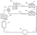
- FIG. 21 is a configuration diagram of a refrigeration cycle of a conventional refrigerator.
- this refrigeration cycle includes a compressor 60, a main condenser 61, a dew-proof pipe 62 for a freezer compartment, a dew-proof pipe 63 for a refrigerator compartment, and a flow path switching valve 64. Further, this refrigeration cycle includes a refrigeration throttle 65, a refrigeration room evaporator 66, a refrigeration room fan 67, a refrigeration throttle 68, a freezing room evaporator 69, and a freezing room fan 70.
- the conventional refrigerator cools the refrigerator compartment (not shown) using the refrigerator compartment evaporator 66 and cools the refrigerator compartment (not shown) using the freezer evaporator 69.
- the dew-proof pipe 63 for the refrigerating room is installed at the opening of the refrigerating room (not shown) to prevent condensation on the wall surface
- the dew-proof pipe 62 for the freezer room is provided in the freezer room (not shown). It is installed in the opening to prevent condensation on the wall surface.
- the refrigerant discharged from the compressor 60 is radiated and liquefied by the main condenser 61 and the dew-proofing pipe 62 for the freezer, and then supplied to the flow path switching valve 64.
- the flow path switching valve 64 is switched to dissipate heat through the refrigerator compartment dew-proof pipe 63, and then the pressure is reduced by the refrigerator refrigerator 65 to the refrigerator compartment evaporator 66. Supply refrigerant and evaporate.
- the refrigerator compartment (not shown) is cooled by driving the refrigerator compartment fan 67.
- the flow path switching valve 64 is switched, the pressure is reduced by the freezing restrictor 68, and the refrigerant is supplied to the freezing room evaporator 69 for evaporation. At this time, the freezer compartment fan 70 is driven to cool the freezer compartment (not shown).
- the freezer compartment (not shown) when the freezer compartment (not shown) is cooled, it can be operated without flowing the refrigerant through the refrigerating room dew-proof pipe 63, and the pressure loss caused by the refrigerating room dew-proof pipe 63 is reduced. Can be suppressed. Further, it is possible to prevent a part of the heat radiated by flowing a refrigerant through the dew-proof pipe 63 for the refrigerating room from entering the refrigerating room (not shown) and becoming a heat load.
- the present invention solves the conventional problem, and by connecting a plurality of dew-proof pipes in parallel via a flow path switching valve on the downstream side of the main condenser, it can be prevented according to the installation environment and operating state of the refrigerator.
- the purpose is to regulate and control the pressure loss and heat load caused by the dew pipe.
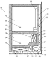
- FIG. 22 is a longitudinal sectional view of a conventional refrigerator
- FIG. 23 is a configuration diagram of a refrigeration cycle of a conventional refrigerator
- FIG. 23 is a waveform diagram of the temperature behavior of the conventional refrigerator temperature sensor and the refrigerator compartment
- FIG. It is a flowchart which shows the control at the time of defrosting.
- the refrigerator 11 includes a housing 12, a door 13, legs 14 that support the housing 12, a lower machine room 15 provided in a lower portion of the housing 12, and a refrigeration disposed in an upper portion of the housing 12. It has the freezer compartment 18 arrange
- a compressor 56 housed in the lower machine chamber 15, an evaporator 20 housed on the back side of the freezer room 18, and a main condenser 21 housed in the lower machine room 15 are provided. Have.
- the refrigerator 11 includes a partition wall 22 that partitions the lower machine room 15, a condenser fan 23 that is attached to the partition wall 22 to air-cool the main condenser 21, an evaporating dish 57 that is installed above the compressor 56, and the lower machine room 15.
- a bottom plate 25 is provided.
- the refrigerator 11 includes a plurality of air inlets 26 provided on the bottom plate 25, an outlet 27 provided on the back side of the lower machine room 15, and a connection connecting the outlet 27 of the lower machine room 15 and the upper part of the housing 12.
- a ventilation path 28 is provided.
- the lower machine chamber 15 is divided into two chambers by the partition wall 22, and the main condenser 21 is housed on the windward side of the condenser fan 23, and the compressor 56 and the evaporating dish 57 are housed on the leeward side.
- the refrigerator 11 is located on the downstream side of the main condenser 21 as components constituting the refrigeration cycle, and includes a dew-proof pipe 37 that is thermally coupled to the outer surface of the housing 12 around the opening of the freezer compartment 18. It is located downstream of the dew pipe 37 and has a dryer 38 for drying the circulating refrigerant, a throttle 38 for connecting the dryer 38 and the evaporator 20 and depressurizing the circulating refrigerant.
- the refrigerator 11 supplies the cooler air generated in the evaporator 20 to the refrigerator compartment 17 and the freezer compartment 18, the evaporator fan 50 that supplies the refrigerator compartment 18, and the refrigerator compartment damper 51 that shuts off the cold air supplied to the refrigerator compartment 18 and the refrigerator compartment 17.
- the freezer damper 51 When the temperature detected by the PCC temperature sensor 55 rises to a predetermined ON temperature, the freezer damper 51 is closed while the compressor 56 is stopped, the refrigerator compartment damper 52 is opened, and the evaporator fan 50 is driven. Thereby, the refrigerator compartment 17 is cooled using the evaporator 20 and the low-temperature sensible heat of the frost adhering to the evaporator 20 and the latent heat of fusion of the frost (hereinafter, this operation is referred to as “off-cycle cooling”).
- the freezer damper 51 is closed, the refrigerator compartment damper 52 is opened, and the compressor 56, the condenser fan 23, and the evaporator fan 50 are driven.
- the condenser fan 23 By driving the condenser fan 23, the main condenser 21 side of the lower machine chamber 15 partitioned by the partition wall 22 becomes negative pressure, and external air is sucked from the plurality of intake ports 26, and the compressor 56 and the evaporating dish 57 side are positive pressure. Then, the air in the lower machine chamber 15 is discharged to the outside from the plurality of discharge ports 27.
- the refrigerant discharged from the compressor 56 is condensed while leaving a part of the gas while exchanging heat with the outside air in the main condenser 21 and then supplied to the dewproof pipe 37.
- the refrigerant that has passed through the dew-proof pipe 37 radiates heat through the housing 12 and condenses while warming the opening of the freezer compartment 18.
- the liquid refrigerant that has passed through the dew-proof pipe 37 is dehydrated by the dryer 38, depressurized by the throttle 39, and is evaporated by the evaporator 20, while exchanging heat with the air in the refrigerator compartment 17 and cooling the refrigerator compartment 17.
- PC cooling gaseous refrigerant
- the freezer damper 51 is opened and refrigerated.
- the chamber damper 52 is closed, and the compressor 56, the condenser fan 23, and the evaporator fan 50 are driven.
- the freezer compartment 18 is cooled by exchanging heat between the inside air of the freezer compartment 18 and the evaporator 20 (hereinafter, this operation is referred to as “FC cooling”).
- section e corresponds to off-cycle cooling
- section f corresponds to PC cooling
- section g corresponds to FC cooling
- section h corresponds to cooling stop operation.
- the compressor 56 is driven between the section f and the section g, and is stopped between the section h and the section e.
- the freezer compartment 18 is cooled during the section g, and the refrigerator compartment 17 is cooled between the section e and the section f.
- the reason why the temperature change in the upper part of the refrigerating chamber 17 is large is that the upper part is adjacent to the high temperature outside air, while the lower part is adjacent to the low temperature freezing room 18, so during the non-cooling period. This is because the temperature difference between the upper and lower sides becomes larger and the air volume at the upper part is increased during cooling to quickly cool the upper part at a high temperature.
- cooling stop when the temperature detected by the FCC temperature sensor 54 falls to a predetermined OFF temperature, the freezer damper 51 and the refrigerator compartment damper 52 are closed, and the compressor 56, the condenser fan 23, and the evaporator fan 50 are stopped.
- this operation is referred to as “cooling stop”.
- a series of operations of off-cycle cooling, PC cooling, FC cooling, and cooling stop are repeated in order.
- off-cycle cooling is performed for a relatively long time (hereinafter, this operation is referred to as “off-cycle differential”).
- FIG. 25 is a flowchart showing control of off-cycle differential from “defrost start” to “defrost end determination”.
- “defrosting start” that is, the start of off-cycle differential. This is aimed at the timing when the temperature in the refrigerator compartment 17 is relatively high and the amount of heat is large in order to melt and remove the frost attached to the evaporator 20 using the amount of heat in the refrigerator compartment 17.
- the freezer damper 51 is closed, the refrigerating room damper 52 is opened, and the evaporator fan 50 is driven. Implement frost.
- the temperature of the evaporator 20 during PC cooling is kept higher than that during FC cooling, so that the efficiency of the refrigeration cycle can be increased and frost adhering to the evaporator 20 by off-cycle cooling.
- energy can be saved by reducing the capacity of the refrigeration cycle necessary for cooling the refrigerator compartment 17 while reducing heater power (not shown) during defrosting.
- the conventional refrigerator configuration has a problem that the time required for off-cycle differential changes greatly depending on the amount of food stored in the refrigerator compartment 17. This is because the amount of heat for melting the frost adhering to the evaporator 20 depends on the amount of heat of the food stored in the refrigerator compartment 17. There is also concern that the frost will not melt completely and the off-cycle differential will not end.
- the frost adhering to the evaporator 20 can be melt
- the present invention solves the conventional problem by determining in advance the amount of heat of the off-cycle differential supplied to the evaporator 20 and appropriately adjusting the output of the auxiliary heating heater.
- the purpose is to properly control the time required for off-cycle differential.
- This invention solves the conventional subject, and aims at suppressing the temperature change of a refrigerator compartment while ensuring the operating time of PC cooling appropriately.
- arrows M1 to M11 indicate mode switching in the conventional refrigerator cooling control.
- the temperature detected by the FCC temperature sensor 54 is a predetermined value of FCC_ON temperature.
- the temperature detected by the PCC temperature sensor 55 rises to a predetermined PCC_ON temperature (that is, the condition of the arrow M1 is satisfied)
- the freezer damper 51 is closed and the refrigerator compartment damper 52 is
- PC cooling mode the operation is referred to as “PC cooling mode”.
- the refrigerant discharged from the compressor 56 is condensed while leaving a part of the gas while exchanging heat with the outside air in the main condenser 21 and then supplied to the dewproof pipe 37.
- the refrigerant that has passed through the dew-proof pipe 37 radiates heat through the housing 12 and condenses while warming the opening of the freezer compartment 18.
- the liquid refrigerant that has passed through the dew-proof pipe 37 is dehydrated by the dryer 38, depressurized by the throttle 39, and is evaporated by the evaporator 20, while exchanging heat with the air in the refrigerator compartment 17 and cooling the refrigerator compartment 17. Then, it returns to the compressor 56 as a gaseous refrigerant.
- the temperature detected by the FCC temperature sensor 54 decreases to a predetermined FCC_OFF temperature
- the temperature detected by the PCC temperature sensor 55 decreases to a predetermined PCC_OFF temperature (that is, the condition of the arrow M2). If the condition is satisfied, the transition is made to the OFF mode.
- the temperature detected by the FCC temperature sensor 54 is higher than a predetermined FCC_OFF temperature, and the temperature detected by the PCC temperature sensor 55 is lowered to the predetermined PCC_OFF temperature (ie, the arrow).
- the freezer damper 51 is opened, the refrigerator compartment damper 52 is closed, and the compressor 56, the condenser fan 23, and the evaporator fan 50 are driven.
- the freezer compartment 18 is heat-exchanged with the inside air of the freezer compartment 18 and the evaporator 20 to cool the freezer compartment 18 (this operation is hereinafter referred to as “FC cooling mode”).
- the temperature detected by the FCC temperature sensor 54 falls to a predetermined FCC_OFF temperature, and the temperature detected by the PCC temperature sensor 55 is equal to or higher than the predetermined PCC_ON temperature (that is, the condition of the arrow M6 is changed). If satisfied, the PC cooling mode is entered.
- the temperature detected by the FCC temperature sensor 54 falls to a predetermined FCC_OFF temperature, and the temperature detected by the PCC temperature sensor 55 indicates a temperature lower than the predetermined PCC_ON temperature (that is, an arrow).
- the mode transits to the OFF mode.
- the defrosting heater (not shown) installed near the evaporator 20 is energized, the compressor 56 is stopped, the freezer compartment damper 51 is closed, the refrigerator compartment damper 52 is opened, and the evaporator fan 50 is driven. (Hereinafter, this operation is referred to as “defrost mode”), the frost adhering to the evaporator 20 is melted and removed, and the refrigerator compartment 17 is cooled using the sublimation heat or heat of fusion of the frost being removed.
- the compressor 56 is stopped, the freezer compartment damper 51 is closed, the refrigerator compartment damper 52 is opened, and the evaporator fan 50 is opened.
- this operation is referred to as “off-cycle cooling mode”
- the refrigerator 20 uses the low-temperature sensible heat of the frost and the sublimation heat or melting heat of the frost adhering to the evaporator 20. 17 is cooled. At this time, the frost attached to the evaporator 20 is not completely thawed and removed, but by reusing the frost attached to the evaporator 20, the power of the heater (not shown) in the defrost mode is reduced. However, the refrigerator compartment 17 can be cooled.
- precool mode In order to cool the freezer compartment 18 to a temperature lower than usual when the predetermined time Tx2 elapses (ie, the condition of the arrow M7 is satisfied) when the power is turned on or when the previous defrost ends during the FC cooling mode. FC cooling is continued for a predetermined time (hereinafter, this operation is referred to as “precool mode”).
- precool mode this operation is referred to as “precool mode”.
- the temperature detected by a DEF temperature sensor (not shown) attached to the evaporator 20 is higher than a predetermined DEF_OFF temperature, or a predetermined time Tx4 elapses from the start of defrosting (ie, When the condition of the arrow M9 is satisfied), a transition to the off-cycle cooling mode is made.
- the state transits to the off-cycle cooling mode.
- the mode transits to the OFF mode.
- the temperature of the evaporator 20 in the PC cooling mode is kept higher than that in the FC cooling mode, so that the efficiency of the refrigeration cycle can be increased and the evaporator 20 is attached to the evaporator 20 by the off-cycle cooling mode.
- energy saving can be achieved by reducing the capacity of the refrigeration cycle necessary for cooling the refrigerator compartment 17 while reducing heater power (not shown) during defrosting. it can.
- the present invention solves the conventional problem, and while maintaining a highly efficient PC cooling mode as much as possible, the temperature rises by appropriately adjusting the cooling amount according to the load balance of the refrigerator compartment or the freezer compartment under an overload condition. It aims at suppressing.
- FIG. 27 is a longitudinal sectional view of a conventional refrigerator
- FIGS. 28 to 31 are flowcharts showing the control of the conventional refrigerator.
- a refrigerator 101 having a freezer compartment 102 and a refrigerator compartment 103 constitutes a refrigeration cycle together with a compressor 104, a condenser (not shown), and a decompression means (not shown), and generates cold air.
- a cooler 105 is included.
- the refrigerator 101 also has a cooling fan 106 that sucks the air in the freezer compartment 102 and the refrigerator compartment 103 into the cooler 105 and re-airs the air to the refrigerator compartment 102 and the refrigerator compartment 103.
- the refrigerator 101 adjusts the communication of the cold air forcedly blown into the freezer compartment 102 by the cooling fan 106 and is forced into the refrigerator compartment 103 by the freezer damper 107 that independently cools the freezer compartment 102 and the cooling fan 106.
- a cold room damper 108 for independently cooling the cold room 103 by adjusting the communication of the cool air to be blown is provided.
- the refrigerator 101 has a freezer compartment sensor 109 that detects the temperature in the freezer compartment 102 and a refrigerator compartment sensor 110 that detects the temperature in the refrigerator compartment 103.
- a defrost heater 111 for defrosting the frost attached to the cooler 105 is provided below the cooler 105, and a cooler sensor 112 that detects the temperature of the cooler 105 is provided in the cooler 105. I have.
- Step S03 if the detected temperature Tfc of the freezer sensor 109 is higher than a reference temperature Tfcon in step S01, the compressor 104 is started if the compressor 104 is not moving in step S02. (Step S03), the freezer compartment damper 107 is opened, the refrigerator compartment damper 108 is closed, and the cooling fan 106 is operated to cool the freezer compartment 102 (Step S04).
- step S05 when the detection temperature Tfc of the freezer compartment sensor 109 is equal to or lower than a reference temperature Tfcoff, the process proceeds to step S06 and the refrigerator compartment cooling mode is set.
- step S06 If the detected temperature Tpc of the refrigerator compartment sensor 110 is higher than a certain reference temperature Tpcon in step S06, the compressor 104 is started if the compressor 104 is not moving in step S07 (step S08), and the freezer damper 107 is closed. Then, the refrigerator compartment damper 108 is opened and the cooling fan 106 is operated to cool the refrigerator compartment 103 (step S09).
- step S10 when the detected temperature Tpc of the refrigerator compartment sensor 110 is equal to or lower than a reference temperature Tpcoff, it is determined whether or not the cooling operation is continued in step S11.
- step S11 if the temperature Tfc detected by the freezer sensor 109 is higher than a certain reference value Tfcon, the process returns to step S02 to enter the freezer cooling mode, and if it is equal to or lower than Tfcon, the process proceeds to step S12 to enter the off-cycle cooling mode. .
- step S12 the compressor 104 is first stopped.
- step S13 when the operation time tcomp of the compressor 104 is shorter than a certain reference value tdefrost, the process proceeds to step S14, and the detection temperature Tpc of the refrigerator compartment sensor 110 is set.
- Tpcoff2 When the value is higher than a certain reference value Tpcoff2, the freezer damper 107 is closed, the refrigerating room damper 108 is opened, and the cooling fan 106 is operated to cool the refrigerating room 103.
- step S13 when the operation time tcomp of the compressor 104 is equal to or greater than a certain reference value tdefrost, the process proceeds to step S18 and the defrosting mode is set.
- step S18 the freezer damper 107 is closed in step S18, the refrigerator compartment damper 108 is closed, the cooling fan 106 is stopped, the defrost heater 111 is energized, and the frost adhering to the cooler 105 is released.
- step S19 when the temperature Tdf detected by the cooler sensor 112 becomes equal to or lower than a certain reference value Tdoff, the power supply to the defrost heater is cut off, the defrost mode is terminated, and normal cooling is performed again from step S1.
- the refrigerating chamber 103 can be cooled using latent heat or sensible heat of frost adhering to the cooler 105, and the energy when defrosting in the defrost mode is reduced.
- a refrigerator that can reduce power consumption by shortening the defrosting time has been proposed (see, for example, Patent Document 3).
- the next defrost mode is started at the same time interval regardless of whether the time of the off cycle cooling mode is long or short after the fully opened defrost mode ends.
- the time is long, the amount of frost adhering to the cooler 105 decreases.
- the refrigerator provided with the freezer damper 107 according to the present invention, it is possible to suppress the wasteful temperature rise of the storage room by predicting the amount of frost attached to the cooler 105 from the operating state and controlling the interval of the defrost mode.
- the object is to provide a refrigerator.
- the refrigerator of the present invention is characterized in that a plurality of dew prevention pipes are connected in parallel via a flow path switching valve on the downstream side of the main condenser.
- the refrigerator of the present invention detects the amount of food stored in the refrigeration room before performing the off-cycle differential, and selects the output of the heater for auxiliary use, and then performs the off-cycle differential. It is a feature. As a result, it is possible to appropriately control the time required for off-cycle differential while suppressing the output of the heater for heating, and to suppress the temperature rise of the refrigerator compartment and freezer compartment during off-cycle differential. The energy consumption of the refrigerator can be reduced by reducing the amount of electric power of the heating heater necessary for defrosting.
- the refrigerator of the present invention is installed above the PCC temperature sensor, the FCC temperature sensor for detecting the temperature of the freezer room, the PCC temperature sensor for detecting the temperature of the refrigerator compartment, and detects the temperature of the upper part of the refrigerator compartment. And a DFP temperature sensor.
- the refrigerator of the present invention opens the freezer damper, closes the cold room damper, closes the freezer damper while operating the freezing cycle, closes the freezer damper, and closes the cold room damper. Open the PC cooling mode to cool the refrigeration room while operating the refrigeration cycle, close the refrigeration room damper, open the refrigeration room damper, and operate the evaporator fan while stopping the refrigeration cycle.
- the time for off-cycle cooling can be adjusted appropriately to ensure sufficient PC cooling time, and the temperature change in the upper part of the refrigerator compartment can be suppressed.
- the energy saving of the refrigerator can be achieved by obtaining.
- the refrigerator of the present invention is characterized by cooling by combining the FC cooling mode, the PC cooling mode, and the off-cycle cooling mode under normal conditions, and cooling by combining the simultaneous cooling mode and the FC cooling mode under overload conditions. To do.
- the refrigerator of the present invention is characterized by cooling by combining the FC cooling mode, the PC cooling mode, and the off-cycle cooling mode under normal conditions, and cooling by combining the simultaneous cooling mode and the FC cooling mode under overload conditions.
- the refrigerator of the present invention includes a first storage chamber having an opening on the front surface, a second storage chamber having an opening on the front surface, a refrigeration cycle including a cooler that generates cold air, and cooling A cooling fan that circulates the cool air generated in the container to the first storage chamber and the second storage chamber, a first damper that selectively flows the cool air from the cooling fan to the first storage chamber, and the cool air from the cooling fan And a defrost heater for removing frost attached to the cooler by heat.
- the refrigerator of the present invention operates the cooling fan when the refrigeration cycle is stopped, and opens the first damper or the second damper to cool the first storage chamber or the second storage chamber.
- the configuration is characterized by controlling the interval from the end of the defrosting mode to the next defrosting mode. Yes.
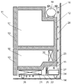
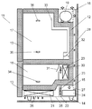
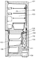
- FIG. 1 is a longitudinal sectional view of a refrigerator in the first embodiment of the present invention.
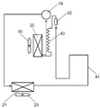
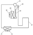
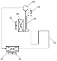
- FIG. 2 is a cycle configuration diagram of the refrigerator in the first embodiment of the present invention.
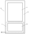
- FIG. 3 is a front view of the refrigerator according to the first embodiment of the present invention.
- FIG. 4 is a configuration diagram of the back surface of the refrigerator in the first embodiment of the present invention.
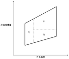
- FIG. 5 is a schematic diagram of the control pattern of the refrigerator in the first embodiment of the present invention.
- FIG. 6 is a longitudinal sectional view of the refrigerator in the second embodiment of the present invention.
- FIG. 7 is a cycle configuration diagram of the refrigerator in the second embodiment of the present invention.
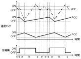
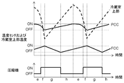
- FIG. 8 is a waveform diagram of the temperature sensor behavior of the refrigerator in the second embodiment of the present invention.
- FIG. 1 is a longitudinal sectional view of a refrigerator in the first embodiment of the present invention.
- FIG. 2 is a cycle configuration diagram of the refrigerator in the first embodiment of the present invention.
- FIG. 3 is a front view
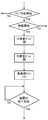
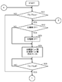
- FIG. 9 is a flowchart showing control during defrosting of the refrigerator according to the second embodiment of the present invention.
- FIG. 10 is a longitudinal sectional view of a refrigerator in the third embodiment of the present invention.
- FIG. 11 is a cycle configuration diagram of the refrigerator in the third embodiment of the present invention.
- FIG. 12 is a waveform diagram of the temperature sensor behavior of the refrigerator in the third embodiment of the present invention.
- FIG. 13 is a longitudinal sectional view of a refrigerator in the fourth embodiment of the present invention.
- FIG. 14 is a cycle configuration diagram of the refrigerator in the fourth embodiment of the present invention.
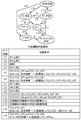
- FIG. 15 is a diagram showing state transitions and switching conditions in the cooling control of the refrigerator in the fourth embodiment of the present invention.
- FIG. 10 is a longitudinal sectional view of a refrigerator in the third embodiment of the present invention.
- FIG. 11 is a cycle configuration diagram of the refrigerator in the third embodiment of the present invention.
- FIG. 12 is a waveform diagram of the temperature sensor behavior of the refrigerator in the third
- FIG. 16 is a longitudinal sectional view of a refrigerator in the fifth embodiment of the present invention.
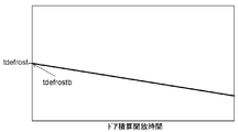
- FIG. 17 is a diagram illustrating the relationship between the interval between the defrost modes of the refrigerator and the accumulated time in the off-cycle cooling mode according to the fifth embodiment of the present invention.
- FIG. 18 is a diagram showing the relationship between the interval of the defrosting mode of the refrigerator and the door integrated opening time in the fifth embodiment of the present invention.
- FIG. 19 is a diagram showing the relationship between the interval of the defrosting mode of the refrigerator and the outside air humidity in the fifth embodiment of the present invention.
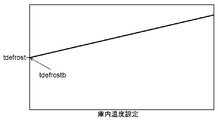
- FIG. 20 is a diagram illustrating the relationship between the interval of the defrosting mode of the refrigerator and the internal temperature setting in the fifth embodiment of the present invention.
- FIG. 21 is a cycle configuration diagram of a conventional refrigerator.
- FIG. 22 is a longitudinal sectional view of a conventional refrigerator.
- FIG. 23 is a cycle configuration diagram of a conventional refrigerator.
- FIG. 24 is a waveform diagram of the temperature behavior of the temperature sensor and the upper part of the refrigerator in the conventional refrigerator.
- FIG. 25 is a flowchart showing control during defrosting of a conventional refrigerator.
- FIG. 26 is a diagram showing state transitions and switching conditions in cooling control of a conventional refrigerator.
- FIG. 27 is a longitudinal sectional view of a conventional refrigerator.
- FIG. 28 is a flowchart showing control of a conventional refrigerator.
- FIG. 29 is a flowchart showing control of a conventional refrigerator.
- FIG. 30 is a flowchart showing control of a conventional refrigerator.
- FIG. 31 is a flowchart showing control of a conventional refrigerator.
- FIG. 1 is a longitudinal sectional view of a refrigerator according to the first embodiment of the present invention
- FIG. 2 is a cycle configuration diagram of the refrigerator according to the first embodiment of the present invention
- FIG. 3 is a first embodiment of the present invention.
- 4 is a schematic diagram of the front of the refrigerator in FIG. 4
- FIG. 4 is a schematic diagram of the back of the refrigerator in the first embodiment of the present invention
- FIG. 5 is a schematic diagram of the control pattern of the refrigerator in the first embodiment of the present invention. .
- the refrigerator 11 includes a housing 12, a door 13, and legs 14 that support the housing 12.
- the refrigerator 11 is provided in a lower machine room 15 provided in a lower portion of the housing 12 and an upper rear portion of the housing 12.
- An upper machine room 16, a refrigerating room 17 that is a storage room arranged at the upper part of the housing 12, and a freezer room 18 arranged at the lower part of the housing 12 are formed.
- the refrigeration cycle includes a compressor 19 housed in the upper machine room 16, an evaporator 20 housed in the back side of the freezer room 18, and a main condenser having a large heat dissipation among the condensers housed in the lower machine room 15. 21.
- the main condenser 21 is composed of a spiral fin tube in which a strip-shaped fin is wound around a refrigerant pipe having an inner diameter of about 4.5 mm.
- the lower machine chamber 15 includes a plurality of intake ports 26 provided in the bottom plate 25, a discharge port 27 provided on the back side of the lower machine chamber 15, a discharge port 27 of the lower machine chamber 15, and the upper machine chamber 16.
- a connecting air passage 28 is provided.
- the lower machine chamber 15 is divided into two chambers by a partition wall 22, and a main condenser 21 is housed on the windward side of the condenser fan 23 and an evaporating dish 24 is housed on the leeward side.
- a condenser in addition to the main condenser 21, a first condenser disposed in the opening of the freezing chamber 18, which is a sub-condenser that dissipates high-temperature heat in the refrigeration cycle.
- a dew-proof pipe 1 and a second dew-proof pipe 2 disposed on the back side of the housing 12 are provided.
- a flow path switching valve 3 that connects the downstream side of the main condenser 21 and the first and second dew-proof pipes 1 and 2 that are sub-condensers, the downstream side of the first dew-proof pipe 1 and the second dew-proofing.
- a junction 4 connecting the downstream sides of the pipe 2, a dryer 5 installed downstream of the junction 4, and a throttle 6 installed downstream of the dryer 5 are provided.
- the first dew-proof pipe 1 and the second dew-proof pipe 2 are made of refrigerant pipes having an inner diameter of about 3.2 mm, and are thermally coupled to the outer surface of the housing 12.
- the flow path switching valve 3 is switched to open the connection to the first dew-proof pipe 1 and open the connection to the second dew-proof pipe 2, and in conjunction with the operation of the compressor 19,
- the condenser fan 23 is driven.
- the main condenser 21 side of the lower machine chamber 15 partitioned by the partition wall 22 has a negative pressure, and external air is sucked from the plurality of intake ports 26, and the evaporating dish 24 side has a positive pressure.
- the air in 15 is discharged to the outside through a plurality of discharge ports 27.
- the refrigerant discharged from the compressor 19 is condensed while leaving a part of the gas while exchanging heat with the outside air in the main condenser 21, and is then connected to the first dew-proof pipe 1 and the first through the flow path switching valve 3. 2 Supplied to the dew proof pipe 2.
- the pipe of the main condenser 21 is in the initial stage where the refrigerant condenses, and there is more gaseous refrigerant than the first dew-proof pipe 1 and the second dew-proof pipe 2 and the flow rate is relatively fast.
- a pipe having an inner diameter larger than that of the first dew-proof pipe 1 and the second dew-proof pipe 2, preferably a pipe having an inner diameter of 4 mm or more is preferably used.
- the refrigerant that has passed through the first dew-proof pipe 1 dissipates heat and condenses outside through the housing 12 while warming the opening of the freezer compartment 18, and the refrigerant that has passed through the second dew-proof pipe 2 While the back surface of the body 12 is warmed, heat is radiated to the outside through the housing 12 and condensed.
- the liquid refrigerant that has passed through the first dew-proof pipe 1 and the second dew-proof pipe 2 is water-removed by the dryer 5, depressurized by the throttle 6, and evaporated in the evaporator 20 while being stored in the refrigerator compartment 17 and the freezer compartment 18. After exchanging heat with air, it is returned to the compressor 19 as a gaseous refrigerant.
- the flow path switching valve 3 is switched to close the connection to the first dew prevention pipe 1 and open the connection to the second dew prevention pipe 2.
- the refrigerant discharged from the compressor 19 is condensed while leaving a part of the gas while exchanging heat with the outside air in the main condenser 21, and then the second refrigerant as a sub-condenser via the flow path switching valve 3.
- coolant which passed the 2nd dew prevention pipe 2 is thermally radiated and condensed through the housing
- the first dew-proof pipe 1 in which the refrigerant does not flow from the flow path switching valve 3 does not radiate heat and eliminates the temperature difference from the surroundings.
- the high-pressure refrigerant flows from the junction 4 and the first dew prevention pipe 1 is almost filled with the liquid refrigerant.
- the liquid refrigerant does not move while staying in the piping of the first dew prevention pipe 1 that is not used on the high pressure side of the refrigeration cycle, and the total amount of refrigerant circulating in the refrigeration cycle is reduced.
- a pipe having an inner diameter smaller than that of the main condenser 21 is used in order to suppress a decrease in the amount of refrigerant circulating in the refrigeration cycle. It is desirable to use a pipe having an inner diameter of less than 4 mm.
- the liquid refrigerant that has passed through the second dew-proof pipe 2 is moisture-removed by the dryer 5, depressurized by the throttle 6, and exchanged heat with the air in the refrigerator compartment 17 and the freezer compartment 18 while evaporating in the evaporator 20. Then, it returns to the compressor 19 as a gaseous refrigerant.
- the first dew prevention pipe 1 is not used, and the refrigerant flows through the second dew prevention pipe 2 to reduce the heat load caused by the first dew prevention pipe 1.
- the first dew-proof pipe 1 is not used on the assumption that the humidity of the outside air is low and it is not necessary to prevent condensation around the opening of the freezer compartment 18. If there is no need to prevent dew condensation in an open space and the humidity of the outside air is relatively high, it may be selected that the second dew prevention pipe 2 is not used and the refrigerant flows through the first dew prevention pipe 1.
- the user can select and use the first dew-proof pipe 1 and the second dew-proof pipe 2 in accordance with the dew condensation condition around the casing 12, so that the selection can be more suitable for the installation environment.
- the heat load can be reduced more efficiently while avoiding the problem of occurrence.
- the condenser fan 23 is stopped and the flow path switching valve 3 is switched to open the connection to the first dew prevention pipe 1 and open the connection to the second dew prevention pipe 2.
- the refrigerant discharged from the compressor 19 passes through the main condenser 21 with little heat exchange with the outside air, and then passes through the flow path switching valve 3 to the first dew-proof pipe 1 and the second dew-proof pipe. 2 is supplied.
- the reason for stopping the condenser fan 23 is to avoid a slow cooling state.
- the condenser fan 23 is driven under a low outside air temperature condition, all the refrigerant is condensed in the main condenser 21, and the amount of the refrigerant supplied to the evaporator 20 is insufficient, so that the cooling of the freezer compartment 18 becomes dull. Is likely to occur.
- the main condenser 21 uses a pipe having a larger inner diameter than the first dew-proof pipe 1 and the second dew-proof pipe 2 which are sub-condensers from the viewpoint of suppressing pressure loss under high load conditions and normal load conditions. Therefore, when the liquid refrigerant stays, the refrigerant amount is likely to be insufficient.
- the condenser fan 23 is stopped, and the refrigerant is allowed to flow in parallel to the first dew-proof pipe 1 and the second dew-proof pipe 2, thereby ensuring the condensing capacity of the refrigeration cycle while suppressing pressure loss.
- the refrigerant that has passed through the first dew-proof pipe 1 dissipates heat and condenses outside through the housing 12 while warming the opening of the freezer compartment 18, and the refrigerant that has passed through the second dew-proof pipe 2 While the back surface of the body 12 is warmed, heat is radiated to the outside through the housing 12 and condensed.
- the liquid refrigerant that has passed through the first dew-proof pipe 1 and the second dew-proof pipe 2 is water-removed by the dryer 5, depressurized by the throttle 6, and evaporated in the evaporator 20 while being stored in the refrigerator compartment 17 and the freezer compartment 18. After exchanging heat with air, it is returned to the compressor 19 as a gaseous refrigerant.
- the condenser fan 23 is stopped, and the coolant is caused to flow in parallel through the first dew-proof pipe 1 and the second dew-proof pipe 2 so that the cooling state is insufficient due to insufficient refrigerant amount.
- the pressure loss caused by the dew-proof pipe can be suppressed while avoiding the above.
- the horizontal axis represents the ambient temperature around the refrigerator 11
- the vertical axis represents the refrigerant circulation amount of the refrigeration cycle
- the range enclosed by a frame schematically represents the operating range of the refrigeration cycle.
- the operating ranges indicated by P, Q, and R indicate ranges of high load conditions, normal conditions, and low outside air temperature conditions, respectively.
- the operating range R including at least the range where the outside air temperature is 10 ° C. or less is set as the range of the low outside air temperature condition. Is desirable. Further, an operating range P in which the outside air temperature is higher than the operating range R and the refrigerant circulation amount is a predetermined value or more is set as a high load condition range, the outside air temperature is higher than the operating range R, and the refrigerant circulation amount is predetermined. The operating range Q less than the value is set as the normal condition range.
- the rotation speed of the compressor is 42 r / s or more and the refrigerant circulation rate exceeds 1.5 kg / hour under normal use conditions, the rotation speed is at least 42 r.
- the same effect can be expected even if it is defined as being in the operating range P when it is at least / s.
- the rotation speed of the compressor is 30 r / s or less and the refrigerant circulation rate is less than 1.5 kg / hour under normal use conditions.
- the operating range Q is defined as being at least 30 r / s or less.
- the refrigerator in the present embodiment is arbitrarily selected by connecting the first dew-proof pipe 1 and the second dew-proof pipe 2 in parallel via the flow path switching valve 3 on the downstream side of the main condenser 21.
- the pressure loss and heat load resulting from the 1st dew-proof pipe 1 and the 2nd dew-proof pipe 2 are adjusted and controlled by the installation environment and operation state of the refrigerator.
- the first dew-proof pipe 1 and the second dew-proof pipe 2 can be simultaneously used in parallel at the time of a high load with a large refrigerant circulation amount to reduce the refrigerant circulation amount and suppress the pressure loss.
- the first dew-proof pipe 1 is not used, and the heat load caused by the first dew-proof pipe 1 can be suppressed.
- FIG. 6 is a longitudinal sectional view of a refrigerator according to the second embodiment of the present invention
- FIG. 7 is a cycle configuration diagram of the refrigerator according to the second embodiment of the present invention
- FIG. 8 is a second embodiment of the present invention.
- FIG. 9 is a flowchart showing the control during defrosting of the refrigerator in the second embodiment of the present invention.
- the refrigerator 11 includes a housing 12, a door 13, a leg 14 that supports the housing 12, a lower machine room 15 provided in a lower portion of the housing 12, and an upper portion provided in an upper portion of the housing 12. It has a machine room 16, a refrigeration room 17 disposed at the upper part of the casing 12, and a freezing room 18 disposed at the lower part of the casing 12.
- a compressor 19 housed in the upper machine room 16 an evaporator 20 housed in the back side of the freezer room 18, and a main condenser 21 housed in the lower machine room 15 are provided.
- partition wall 22 that partitions the lower machine chamber 15, a condenser fan 23 that is attached to the partition wall 22 to air-cool the main condenser 21, an evaporating dish 24 installed on the leeward side of the partition wall 22, and a bottom plate 25 of the lower machine chamber 15. is doing.
- a plurality of air intakes 26 provided in the bottom plate 25, an exhaust port 27 provided on the back side of the lower machine room 15, and a communication air passage 28 connecting the exhaust port 27 of the lower machine room 15 and the upper machine room 16 are provided.
- the lower machine chamber 15 is divided into two chambers by a partition wall 22, and a main condenser 21 is housed on the windward side of the condenser fan 23 and an evaporating dish 24 is housed on the leeward side.
- the dew-proof pipe 41 and the dew-proof pipe 41 which are located on the downstream side of the main condenser 21 and are thermally coupled to the outer surface of the housing 12 around the opening of the freezer compartment 18 are provided. It is located downstream, and has a dryer 42 that dries the circulating refrigerant, a throttle 42 that combines the dryer 42 and the evaporator 20 and depressurizes the circulating refrigerant.
- an evaporator fan 30 that supplies cold air generated in the evaporator 20 to the refrigerator compartment 17 and the freezer compartment 18, a freezer damper 31 that blocks cold air supplied to the freezer compartment 18, and cold air supplied to the refrigerator compartment 17
- the refrigerator compartment damper 32 to be shut off, the duct 33 for supplying cold air to the refrigerator compartment 17, the FCC temperature sensor 34 for detecting the temperature of the freezer compartment 18, the PCC temperature sensor 35 for detecting the temperature of the refrigerator compartment 17, and the upper part of the refrigerator compartment 17 It has a DFP temperature sensor 36 that is located and detects the temperature of the refrigerator compartment 17 above the PCC temperature sensor 35, and a heater 44 that is installed below the evaporator 20 and serves as an auxiliary heat source during defrosting. .
- the duct 33 is formed along a wall surface where the refrigerator compartment 17 and the upper machine room 16 are adjacent to each other, and a part of the cold air passing through the duct 33 is discharged from the vicinity of the center of the refrigerator compartment, and most of the cold air is in the upper machine. After passing through the wall 16 while cooling the adjacent wall surface, it is discharged from the upper part of the refrigerator compartment 17.
- the freezer damper 31 When the temperature detected by the DFP temperature sensor 36 rises to a predetermined ON temperature, the freezer damper 31 is closed with the compressor 19 stopped, the refrigerator damper 32 is opened, and the evaporator fan 30 is driven.
- the refrigerator compartment 17 is cooled by utilizing the low-temperature sensible heat of the evaporator 20 and the frost adhering to the evaporator 20 and the latent heat of melting of the frost (this operation is hereinafter referred to as “off-cycle cooling”).
- this operation is hereinafter referred to as “off-cycle cooling”.
- the freezer damper 31 When the temperature detected by the PCC temperature sensor 35 rises to a predetermined ON temperature during off-cycle cooling or cooling stop, the freezer damper 31 is closed, the refrigerator compartment damper 32 is opened, and the compressor 19 and the condenser fan 23 are opened. The evaporator fan 30 is driven.
- the main condenser 21 side of the lower machine chamber 15 partitioned by the partition wall 22 has a negative pressure, and external air is sucked from the plurality of intake ports 26, and the evaporating dish 24 side has a positive pressure.
- the air in 15 is discharged to the outside through a plurality of discharge ports 27.
- the air discharged from the lower machine room 15 is sent to the upper machine room 16 via the communication air passage 28 to cool the compressor 19.
- the refrigerant discharged from the compressor 19 is condensed while leaving a part of the gas while exchanging heat with the outside air in the main condenser 21 and then supplied to the dewproof pipe 41.
- the refrigerant that has passed through the dewproof pipe 41 dissipates heat through the housing 12 and condenses while warming the opening of the freezer compartment 18.
- the liquid refrigerant that has passed through the dew-proof pipe 41 is moisture-removed by the dryer 42, depressurized by the throttle 43, and evaporated by the evaporator 20, while exchanging heat with the air in the refrigerator compartment 17 and cooling the refrigerator compartment 17. Then, it returns to the compressor 19 as a gaseous refrigerant (hereinafter, this operation is referred to as “PC cooling”).
- PC cooling a gaseous refrigerant
- the freezer damper 31 is opened and refrigerated.
- the chamber damper 32 is closed, and the compressor 19, the condenser fan 23, and the evaporator fan 30 are driven.
- the freezer compartment 18 is heat-exchanged with the inside air of the freezer compartment 18 and the evaporator 20 to cool the freezer compartment 18 (this operation is hereinafter referred to as “FC cooling”).
- FC cooling this operation is hereinafter referred to as “FC cooling”.
- off-cycle cooling operates prior to cooling stop during cooling stop, and does not operate during PC cooling or FC cooling.
- PC cooling and FC cooling are operated with priority over off-cycle cooling.
- the OFF temperature at which off-cycle cooling is stopped is set higher than the ON temperature at which PC cooling is started.
- the basic operation is to repeat a series of operations of PC cooling, FC cooling, and cooling stop in order, and while the PC cooling and FC cooling operations are not performed, the cooling stop and off-cycle cooling are performed several times. Repeat repeatedly.
- section a corresponds to PC cooling
- section b corresponds to FC cooling
- section c corresponds to off-cycle cooling
- section d corresponds to cooling stop operation.
- the off-cooling is performed several times while the PC cooling operation and the FC cooling operation are not performed. Since the ratio between the off-cycle cooling and the PC cooling for cooling 17 can be accurately adjusted, the PC cooling operation time can be appropriately ensured.
- the temperature of the DFP temperature sensor 36 provided in the upper part of the refrigerating chamber 17 having a relatively high temperature is set as the PCC temperature sensor.
- the OFF temperature at which off-cycle cooling is stopped is set higher than the ON temperature at which PC cooling is started, but the OFF temperature at which off-cycle cooling is stopped is the OFF temperature at which PC cooling is stopped. The same effect can be obtained even if the value is set higher than the above value.
- the duct 33 is formed on the wall surface of the refrigerating room 17 adjacent to the upper machine room 16 that is hotter than the outside air, thereby cooling the refrigerating room 17 during off-cycle cooling and PC cooling, particularly the refrigerating room 17.
- off-cycle differential the control flow of the off-cycle differential is from “freezer compartment damper close” to “defrost completion determination”.
- the amount of food stored in the refrigerator compartment 17 is determined.
- the heating heater 44 is not energized, and when the amount of food is small, the heating heater 44 is energized. Thereafter, as a series of operations of the off-cycle differential, the freezer compartment damper 31 is closed with the compressor 19 stopped, the refrigerator compartment damper 32 is opened, and the evaporator fan 30 is driven to defrost the evaporator 20. To implement.
- the DFP temperature sensor 36 for detecting the temperature of the upper part of the refrigerator compartment 17 is relatively higher than the PCC temperature sensor 35 in the modes (b, c, d) other than the PC cooling. Cooling (a) tends to approach the PCC temperature sensor 35. This is because cold air is mainly supplied from the upper part of the refrigerator compartment 17 through the duct 33.
- the DFP temperature sensor 36 The temperature to be detected decreases to a temperature that is about the same as or lower than that of the PCC temperature sensor 35.
- the temperature detected by the DFP temperature sensor 36 is lowered only to a temperature relatively higher than the PCC temperature sensor 35. do not do.
- the food stored in the refrigerator compartment 17 It can be determined that the amount is large. Similarly, the amount of food stored in the refrigerator compartment 17 can be determined from the difference in temperature behavior during off-cycle cooling, but the detection accuracy is excellent because the temperature change during PC cooling is greater.
- the refrigerator in the present embodiment estimates the amount of food stored in the refrigerator compartment 17 based on the difference in temperature behavior during the PC cooling between the DFP temperature sensor 36 and the PCC temperature sensor 35. It is possible to directly estimate the amount of heat of the food stored in the container, and to adjust the output of the heating heater 44 with high accuracy.
- the off-cycle differential especially when the amount of food stored in the refrigerator compartment 17 is large, the heating heater 44 is not used, and at the same time, the capacity of the refrigerating cycle necessary for cooling the refrigerator compartment 17 is reduced. Can save energy. At this time, since the amount of food stored in the refrigerator compartment 17 is large and the amount of heat necessary for defrosting the evaporator 20 can be ensured, the off-cycle differential can be completed in an appropriate time.
- the heater 44 is used for heating, and the amount of food stored in the refrigerator compartment 17 and the power output from the heater 44 for heating are used.
- the off-cycle differential can be terminated.
- the refrigerator in the present embodiment switches the heating heater 44 ON / OFF to adjust the heat source of the off-cycle differential, but when the amount of food stored in the refrigerator compartment 17 is large, the output is increased, If the amount of food stored in the refrigerator compartment 17 is small, the same effect can be expected even if the output is reduced and the output of the heating heater 44 is selected.
- the refrigerator in the present embodiment is before the off-cycle differential is performed. After detecting the amount of food stored in the refrigerated room and selecting the output of the heater for auxiliary use, the time required for the off-cycle differential can be appropriately controlled by performing the off-cycle differential. .
- the refrigerator in the present embodiment suppresses the temperature increase in the refrigerator compartment and the freezer compartment during off-cycle differential, and reduces the amount of power of the heating heater necessary for defrosting. Energy saving can be achieved.
- FIG. 10 is a longitudinal sectional view of a refrigerator according to the third embodiment of the present invention
- FIG. 11 is a cycle configuration diagram of the refrigerator according to the third embodiment of the present invention
- FIG. 12 is a third embodiment of the present invention. It is a wave form diagram of the temperature sensor behavior of the refrigerator.
- the refrigerator 11 includes a housing 12, a door 13, legs 14 that support the housing 12, a lower machine room 15 provided in the lower portion of the housing 12, and an upper portion provided in the upper portion of the housing 12. It has a machine room 16, a refrigeration room 17 disposed at the upper part of the casing 12, and a freezing room 18 disposed at the lower part of the casing 12.
- a compressor 19 housed in the upper machine room 16 an evaporator 20 housed in the back side of the freezer room 18, and a main condenser 21 housed in the lower machine room 15 are provided.
- partition wall 22 that partitions the lower machine chamber 15, a condenser fan 23 that is attached to the partition wall 22 to air-cool the main condenser 21, an evaporating dish 24 installed on the leeward side of the partition wall 22, and a bottom plate 25 of the lower machine chamber 15. is doing.
- a plurality of air intakes 26 provided in the bottom plate 25, an exhaust port 27 provided on the back side of the lower machine room 15, and a communication air passage 28 connecting the exhaust port 27 of the lower machine room 15 and the upper machine room 16 are provided.
- the lower machine chamber 15 is divided into two chambers by a partition wall 22, and a main condenser 21 is housed on the windward side of the condenser fan 23 and an evaporating dish 24 is housed on the leeward side.
- a dew-proof pipe 37 and a dew-proof pipe 37 which are located on the downstream side of the main condenser 21 and are thermally coupled to the outer surface of the housing 12 around the opening of the freezer compartment 18. It is located downstream, and has a dryer 38 that dries the circulating refrigerant, a throttle 38 that combines the dryer 38 and the evaporator 20 and depressurizes the circulating refrigerant.
- an evaporator fan 30 that supplies cold air generated in the evaporator 20 to the refrigerator compartment 17 and the freezer compartment 18, a freezer damper 31 that blocks cold air supplied to the freezer compartment 18, and cold air supplied to the refrigerator compartment 17
- the refrigerator compartment damper 32 to be shut off, the duct 33 for supplying cold air to the refrigerator compartment 17, the FCC temperature sensor 34 for detecting the temperature of the freezer compartment 18, the PCC temperature sensor 35 for detecting the temperature of the refrigerator compartment 17, the upper part of the refrigerator compartment 17,
- a DFP temperature sensor 36 for detecting the temperature of the refrigerator compartment 17 above the PCC temperature sensor 35 is provided.
- the duct 33 is formed along a wall surface where the refrigerator compartment 17 and the upper machine room 16 are adjacent to each other, and a part of the cold air passing through the duct 33 is discharged from the vicinity of the center of the refrigerator compartment, and most of the cold air is in the upper machine. After passing through the wall 16 while cooling the adjacent wall surface, it is discharged from the upper part of the refrigerator compartment 17.
- the freezer damper 31 When the temperature detected by the DFP temperature sensor 36 rises to a predetermined ON temperature, the freezer damper 31 is closed with the compressor 19 stopped, the refrigerator damper 32 is opened, and the evaporator fan 30 is driven.
- the refrigerator compartment 17 is cooled by utilizing the low-temperature sensible heat of the evaporator 20 and the frost adhering to the evaporator 20 and the latent heat of melting of the frost (this operation is hereinafter referred to as “off-cycle cooling”).
- this operation is hereinafter referred to as “off-cycle cooling”.
- the freezer damper 31 When the temperature detected by the PCC temperature sensor 35 rises to a predetermined ON temperature during off-cycle cooling or cooling stop, the freezer damper 31 is closed, the refrigerator compartment damper 32 is opened, and the compressor 19 and the condenser fan 23 are opened. Drive.
- the condenser fan 23 When the condenser fan 23 is driven, the main condenser 21 side of the lower machine chamber 15 partitioned by the partition wall 22 has a negative pressure, and external air is sucked from the plurality of intake ports 26, and the evaporating dish 24 side has a positive pressure.
- the air in 15 is discharged to the outside through a plurality of discharge ports 27.
- the air discharged from the lower machine room 15 is sent to the upper machine room 16 via the communication air passage 28 to cool the compressor 19.
- the refrigerant discharged from the compressor 19 is condensed while leaving a part of the gas while exchanging heat with the outside air in the main condenser 21 and then supplied to the dewproof pipe 37.
- the refrigerant that has passed through the dew-proof pipe 37 radiates heat through the housing 12 and condenses while warming the opening of the freezer compartment 18.
- the liquid refrigerant that has passed through the dew-proof pipe 37 is dehydrated by the dryer 38, depressurized by the throttle 39, and is evaporated by the evaporator 20, while exchanging heat with the air in the refrigerator compartment 17 and cooling the refrigerator compartment 17. Then, it returns to the compressor 19 as a gaseous refrigerant (hereinafter, this operation is referred to as “PC cooling”).
- the freezer damper 31 is opened and refrigerated.
- the chamber damper 32 is closed, and the compressor 19, the condenser fan 23, and the evaporator fan 30 are driven.
- the freezer compartment 18 is cooled by exchanging heat between the inside air of the freezer compartment 18 and the evaporator 20 (hereinafter, this operation is referred to as “FC cooling”).
- FC cooling this operation is referred to as “FC cooling”.
- off-cycle cooling operates prior to cooling stop during cooling stop, and does not operate during PC cooling or FC cooling.
- PC cooling and FC cooling are operated with priority over off-cycle cooling.
- the OFF temperature at which the off-cycle cooling is stopped is set higher than the ON temperature at which the PC cooling is started.
- section a corresponds to PC cooling
- section b to FC cooling
- section c to off-cycle cooling
- section d to cooling stop operation.
- the off-cooling is performed several times while the PC cooling operation and the FC cooling operation are not performed. Since the ratio between the off-cycle cooling and the PC cooling for cooling 17 can be accurately adjusted, the PC cooling operation time can be appropriately ensured.
- the temperature of the DFP temperature sensor 36 provided in the upper part of the refrigerating chamber 17 having a relatively high temperature is set as the PCC temperature sensor
- the OFF temperature at which off-cycle cooling is stopped is set higher than the ON temperature at which PC cooling is started, but the OFF temperature at which off-cycle cooling is stopped is the OFF temperature at which PC cooling is stopped. The same effect can be obtained even if the value is set higher than the above value.
- the duct 33 is formed on the wall surface of the refrigerating room 17 adjacent to the upper machine room 16 that is hotter than the outside air, thereby cooling the refrigerating room 17 during off-cycle cooling and PC cooling, particularly the refrigerating room 17.
- the duct 33 is formed on the wall surface of the refrigerating room 17 adjacent to the upper machine room 16 that is hotter than the outside air, thereby cooling the refrigerating room 17 during off-cycle cooling and PC cooling, particularly the refrigerating room 17.
- the refrigerator in the present embodiment has an off-cycle cooling mode (c) for cooling the refrigerator compartment 17 during the refrigeration cycle stop in addition to the FC cooling mode (b) and the PC cooling mode (a).
- the DFP temperature is installed above the PCC temperature sensor 35 that controls the PC cooling and has a temperature change larger than that of the PCC temperature sensor 35.
- FIG. 13 is a longitudinal sectional view of a refrigerator according to the fourth embodiment of the present invention
- FIG. 14 is a cycle configuration diagram of the refrigerator according to the fourth embodiment of the present invention
- FIG. 15 is a fourth embodiment of the present invention. It is the figure which showed the state transition in the cooling control of the refrigerator, and its switching condition.
- the refrigerator 11 includes a housing 12, a door 13, legs 14 that support the housing 12, a lower machine room 15 provided in the lower portion of the housing 12, and an upper portion provided in the upper portion of the housing 12. It has a machine room 16, a refrigeration room 17 disposed at the upper part of the casing 12, and a freezing room 18 disposed at the lower part of the casing 12.
- a compressor 19 housed in the upper machine room 16, an evaporator 20 housed in the back side of the freezer room 18, and a main condenser 21 housed in the lower machine room 15 are provided.
- the compressor 19 is a variable speed compressor and uses six stages of rotation speed selected from 20 to 80 r / s. This is because the refrigerating capacity is adjusted by switching the rotational speed of the compressor 19 to six stages from low speed to high speed while avoiding resonance of piping and the like.
- the compressor 19 operates at a low speed at the time of start-up, and increases as the operation time for cooling the refrigerator compartment 17 or the freezer compartment 18 becomes longer.
- the rotation speed of the compressor 19 is controlled independently of the cooling operation mode of the refrigerator 11, but the rotation speed at the start of the PC cooling mode with a high evaporation temperature and a relatively large refrigerating capacity is set to be higher than that in the FC cooling mode. It may be set low. Further, the refrigeration capacity may be adjusted while decelerating the compressor 19 as the temperature of the refrigerator compartment 17 or the freezer compartment 18 decreases.
- a plurality of air intakes 26 provided in the bottom plate 25, an exhaust port 27 provided on the back side of the lower machine room 15, and a communication air passage 28 connecting the exhaust port 27 of the lower machine room 15 and the upper machine room 16 are provided.
- the lower machine chamber 15 is divided into two chambers by a partition wall 22, and a main condenser 21 is housed on the windward side of the condenser fan 23 and an evaporating dish 24 is housed on the leeward side.
- a dew-proof pipe 37 and a dew-proof pipe 37 which are located on the downstream side of the main condenser 21 and are thermally coupled to the outer surface of the housing 12 around the opening of the freezer compartment 18. It is located downstream, and has a dryer 38 that dries the circulating refrigerant, a throttle 38 that combines the dryer 38 and the evaporator 20 and depressurizes the circulating refrigerant.
- an evaporator fan 30 that supplies cold air generated in the evaporator 20 to the refrigerator compartment 17 and the freezer compartment 18, a freezer damper 31 that blocks cold air supplied to the freezer compartment 18, and cold air supplied to the refrigerator compartment 17
- the duct 33 for supplying cold air to the refrigerator compartment 17, the FCC temperature sensor 34 for detecting the temperature of the freezer compartment 18, the PCC temperature sensor 35 for detecting the temperature of the refrigerator compartment 17, and the upper part of the refrigerator compartment 17
- a DFP temperature sensor 36 for detecting the temperature of the refrigerator compartment 17 above the PCC temperature sensor 35 is provided.
- the duct 33 is formed along a wall surface where the refrigerator compartment 17 and the upper machine room 16 are adjacent to each other, and a part of the cold air passing through the duct 33 is discharged from the vicinity of the center of the refrigerator compartment, and most of the cold air is in the upper machine. After passing through the wall 16 while cooling the adjacent wall surface, it is discharged from the upper part of the refrigerator compartment 17.
- arrows L1 to L15 indicate mode switching in the cooling control of the refrigerator in the fourth embodiment of the present invention.
- the detailed description of the same cooling operation mode and mode switching conditions as those of the conventional refrigerator shown in FIG. 26 is omitted.
- the condition of the arrow L1 (that is, the condition of the arrow M1) is satisfied, or the temperature detected by the DFP temperature sensor 36 rises to a predetermined DFP_ON temperature (that is, the condition of the arrow L10 is satisfied) To transition to the off-cycle cooling mode.
- the mode transits to the OFF mode. Further, when the condition of the arrow L1 (that is, the condition of the arrow M1) is satisfied during the off-cycle cooling mode, the PC cooling mode is transitioned to.
- the time in the off-cycle cooling mode can be appropriately adjusted using the DFP temperature sensor 36 installed in the upper part of the refrigerator compartment 17. Since the conventional refrigerator always performs off-cycle cooling for a certain time Td, there is a concern that the temperature of the refrigerator compartment 17 is unnecessarily lowered.
- the temperature detected by the FCC temperature sensor 34 is higher than the predetermined FCC_OFF temperature, and the temperature detected by the PCC temperature sensor 35 falls to the predetermined PCC_OFF temperature (that is, the arrow L5 If the condition is satisfied), transition to the FC cooling mode.
- the difference between the temperature detected by the FCC temperature sensor 34 and the FCC_OFF temperature of the predetermined value is detected by the PCC temperature sensor 35 after the predetermined time Tx1 has elapsed during the PC cooling mode.
- the transition to the FC cooling mode is made.
- the temperature detected by the FCC temperature sensor 34 falls to a predetermined FCC_OFF temperature, and the temperature detected by the PCC temperature sensor 35 is equal to or higher than the predetermined PCC_ON temperature (that is, the condition indicated by the arrow L6). If satisfied, the PC cooling mode is entered.
- the difference between the temperature detected by the FCC temperature sensor 34 and the FCC_OFF temperature of the predetermined value is detected by the PCC temperature sensor 35 after the predetermined time Tx1 has elapsed during the FC cooling mode.
- the PC cooling mode is entered.
- the PC cooling mode and the FC cooling mode are alternately switched every predetermined time Tx1, and the cooling is ended. It is possible to preferentially cool the one having a larger deviation from the OFF temperature. As a result, the cooling operation time can be distributed more flexibly than the time-fixed alternating cooling performed in the conventional refrigerator.
- the compressor 19, the condenser fan 23, and the evaporator fan 30 are driven by opening the freezer damper 31 and the refrigerator compartment damper 32.
- the condenser fan 23 when the condenser fan 23 is driven, the main condenser 21 side of the lower machine chamber 15 partitioned by the partition wall 22 has a negative pressure, and external air is sucked from the plurality of intake ports 26, and the compressor 19 The evaporating dish 57 side becomes positive pressure, and the air in the lower machine chamber 15 is discharged to the outside from the plurality of discharge ports 27.
- the refrigerant discharged from the compressor 19 is condensed while leaving a part of the gas while exchanging heat with the outside air in the main condenser 21 and then supplied to the dewproof pipe 37.
- the refrigerant that has passed through the dew-proof pipe 37 radiates heat through the housing 12 and condenses while warming the opening of the freezer compartment 18.
- the liquid refrigerant that has passed through the dew-proof pipe 37 is water-removed by the dryer 38, depressurized by the throttle 39, and heat-exchanged with the air in the refrigerator compartment 17 and the freezer compartment 18 while being evaporated by the evaporator 20, and the refrigerator compartment 17 And while cooling the freezer compartment 18, it recirculate
- the evaporator fan 30 is rotated at a high speed to secure an air volume necessary for cooling the refrigerator compartment 17 and the freezer compartment 18 in parallel.
- air that has a high wind speed at a high temperature flows into the evaporator 20, so that the temperature of the blown air from the evaporator 20 tends to rise. It is desirable to ensure proper refrigeration capacity by operating When the compressor 19 is operated at a low speed in the simultaneous cooling mode, there is a concern that the temperature of the air blown from the evaporator 20 increases and the freezer compartment 18 cannot be cooled to a low temperature.
- the mode is changed to the simultaneous cooling mode and the compressor is moved during the simultaneous cooling mode.
- the rotational speed of 19 is less than the predetermined rotational speed (that is, the condition of the arrow L13 is satisfied)
- the PC cooling mode is entered.
- the mode switching between the arrow L12 and the arrow L13 is performed with priority over other state transitions. This is because the rotation speed of the compressor 19 is increased to a predetermined rotation speed or more, so that it is detected that the refrigerator 11 is in an overload condition and the mode is changed to the simultaneous cooling mode. This is to avoid that the temperature of the air blown from the evaporator 20 rises and the freezer compartment 18 cannot be cooled to a low temperature when the rotation speed is less than the predetermined number of revolutions.
- the mode is changed to the FC cooling mode. This is to continue the simultaneous cooling mode up to the upper temperature limit at which the freezer compartment 18 is allowed in order to suppress the temperature rise of the refrigerator compartment 17 that is not cooled during the FC cooling mode.
- the FCC_LIM temperature detected by the FCC temperature sensor 34 is a predetermined value corresponding to weak cooling that is 2 to 5 ° C. higher than the FCC_ON temperature, which is the upper limit temperature during normal cooling.
- condition of the arrow L12 for transitioning to the simultaneous cooling mode corresponding to the overload condition is defined by the number of revolutions of the compressor 19.
- the power is turned on at high outside air temperature and the door is frequently opened and closed. May be detected and a transition to the simultaneous cooling mode may be made.
- condition of the arrow L13 may be changed so that the simultaneous cooling mode is canceled by detecting that the temperature of the refrigerator compartment 17 or the freezer compartment 18 is lowered to some extent.
- the most efficient PC cooling mode can be used for a longer time.
- the temperature detected by the FCC temperature sensor 34 indicates a temperature lower than the predetermined FCC_LIM temperature
- the temperature detected by the PCC temperature sensor 35 indicates a temperature higher than the predetermined PCC_OFF temperature.
- the evaporator fan 30 is rotated at a high speed to secure the amount of air sent in parallel to both the refrigerator compartment 17 and the freezer compartment 18, but when a large amount of frost is formed in the evaporator 20.
- the sufficient air volume cannot be secured.
- the air volume in the refrigerator compartment 17 having a relatively long path for blowing air from the evaporator 20 is greatly reduced, and the cold air in the upper part of the refrigerator compartment 17 is reduced.
- the temperature difference between the DFP temperature sensor 36 that is relatively close to the blowing position and the PCC temperature sensor 35 near the center of the refrigerator compartment 17 becomes smaller than the predetermined value ⁇ .
- the cooling state of the refrigerator compartment 17 in the simultaneous cooling mode is normal or the evaporator 20 is attached. It can be detected whether the refrigeration room 17 has a slow cooling tendency due to frost, and when the refrigeration room 17 has a slow cooling tendency, the cooling capacity of the refrigeration room 17 is quickly recovered by reducing the defrosting interval of the evaporator 20. can do.
- the refrigerator in the present embodiment is a refrigerator having an off-cycle cooling mode that cools the refrigerator compartment while the refrigeration cycle is stopped in addition to the FC cooling mode and the PC cooling mode.
- the amount of cooling in the freezer and freezer compartments can be adjusted automatically and appropriately under overload conditions, thereby increasing the temperature of the refrigerator compartment and freezer compartment. Can be suppressed.
- FIG. 16 is a longitudinal sectional view of a refrigerator in the fifth embodiment of the present invention.
- FIG. 17 is a diagram showing the relationship between the interval of the defrosting mode of the refrigerator and the accumulated time of the off-cycle cooling mode in the fifth embodiment of the present invention.
- FIG. 18 is a diagram showing the relationship between the interval of the defrosting mode of the refrigerator and the integrated door opening time in the fifth embodiment of the present invention.
- FIG. 19 is a diagram showing the relationship between the interval of the defrosting mode of the refrigerator and the outside air humidity in the fifth embodiment of the present invention.
- FIG. 20 is a diagram showing the relationship between the interval of the defrosting mode of the refrigerator and the internal temperature setting in the fifth embodiment of the present invention.
- the refrigerator in the present embodiment has a freezer compartment door 113 that seals the opening of the freezer compartment 102 so that it can be opened and closed, and a refrigerator compartment door 114 that seals the opening of the refrigerator compartment 103 so that it can be opened and closed.
- the opening and closing of the freezer compartment door 113 and the refrigerator compartment door 114 are detected, for example, a freezer compartment door sensor 115 composed of a Hall IC and a magnet and the refrigerator compartment.
- a door sensor 116 is provided.
- a humidity sensor 117 for detecting the humidity of the outside air is provided on the outer wall side of the refrigerator 101, and the operation of the refrigeration cycle is controlled inside, the control state of the refrigeration cycle, the freezer compartment door sensor 115, the refrigerator compartment.
- a control unit 118 that performs operation control of the refrigeration cycle based on the outputs of the door sensor 116 and the humidity sensor 117 is provided.
- step S12 when the compressor 104 is stopped in step S12 shown in FIG. 30, if the operation time tcomp of the compressor 104 is tdefrost or more in step S13, the process proceeds to step S18 shown in FIG.
- Tdefrost has a certain initial value tdefrostb and fluctuates depending on the off-cycle cooling time, door opening / closing time, outside air humidity, and internal temperature setting.
- the refrigerator compartment 107 is closed, the refrigerator compartment damper 108 is opened, and the cooling fan 106 is operated to cool the refrigerator compartment 103 using latent heat or sensible heat of frost attached to the cooler 105.
- the cooling fan 106 is operated to cool the refrigerator compartment 103 using latent heat or sensible heat of frost attached to the cooler 105.
- heat is taken away from the frost adhering to the cooler 105. For this reason, the amount of heat necessary for defrosting the cooler 105 decreases as the off-cycle cooling time increases.
- the integration time of off-cycle cooling is counted by the control unit 118, and is controlled by the control unit 118 so that tdefrost becomes longer as the integration time becomes longer.
- tdefrost can be changed according to the degree of frost formation on the cooler 105 due to the accumulated time of off-cycle cooling, the number of operations in the defrosting mode can be optimized, and the temperature rise in the warehouse is appropriately prevented. be able to.
- the freezer compartment door 113 or the refrigerator compartment door 114 is opened and closed to take out food in the storage compartment.
- high-temperature and high-humidity outside air flows into the storage chamber as compared to the storage chamber air dehumidified and circulated by the cooler 105.
- frost formation on the cooler 105 occurs. Therefore, if the door opening / closing time is long, the amount of frost formation on the cooler 105 increases, and conversely, if the door opening / closing time is short, the amount of frost formation decreases.
- the door opening integration time is counted by the freezer compartment door sensor 115 and the refrigerator compartment door sensor 116, and is output to the control unit 118.
- the longer the door opening / closing integration time the shorter the tdefrost becomes. I have control.
- tdefrost can be changed in accordance with the degree of frost formation on the cooler 105 based on the door opening / closing integrated time, the number of operations in the defrosting mode can be optimized, and the temperature rise in the warehouse can be appropriately prevented. it can.
- the freezer compartment 102 and the refrigerator compartment 103 are hermetically sealed by the freezer compartment door 113 and the refrigerator compartment door 114, but are not completely sealed, and have a minute gap from which indoor and outdoor air can flow.
- the humidity of the outside air flows into the cabinet.
- the humidity of the outside air flows into the room when the door is opened and closed. Therefore, when the outside air humidity is high, the humidity entering the compartment is also high, and the amount of frost formation on the cooler 105 is increased. Conversely, when the outside air humidity is low, the amount of frost formation is reduced.
- the outside air humidity is measured by the humidity sensor 117, and the average humidity from the fully-open defrost mode is calculated and output to the control unit 118.
- the control is performed so that the higher the outside air humidity is, the shorter the tdefrost becomes. This is controlled by the unit 118.
- tdefrost can be changed according to the degree of frost formation on the cooler 105 due to the outside air humidity, the number of operations in the defrost mode can be optimized, and the temperature rise in the warehouse can be appropriately prevented.
- the internal temperature setting is detected by the control unit 118, and is controlled by the control unit 118 so that the higher the internal temperature setting, the longer tdefrost becomes.
- tdefrost can be changed according to the degree of frost formation on the cooler 105 by the internal temperature setting, the number of operations in the defrosting mode can be optimized, and the internal temperature can be prevented appropriately. it can.
- the refrigerator in the present embodiment can prevent a temperature rise in the refrigerator, and thus can be a refrigerator with high cooling performance.
- tdefrost is described as a control method in which proportional control is performed with respect to the increase / decrease of each control factor. The effect is obtained, and there is an advantage that the control becomes simple.
- the off-cycle cooling is controlled to be terminated by the temperature detected by the cold room sensor 110.
- the off-cycle cooling may be controlled by, for example, determining the off-cycle cooling time or by other control factors. Similar effects can be obtained.
- the refrigerator is described as two refrigerators, a freezer compartment 102 and a refrigerator compartment 103, but the same control is performed regardless of the number of storage compartments, such as a three-room refrigerator equipped with a vegetable compartment. Similar effects can be obtained.
- control for detecting the outside air humidity has been described.
- more optimal control can be performed. It can be carried out.
- the refrigerator in this Embodiment demonstrated by the specification which produces
- the present invention includes a forced air-cooled main condenser, a flow path switching valve connected to the downstream side of the main condenser, and a plurality of parallel connection downstream of the flow path switching valve.
- the refrigerator has a dew-proof pipe and flows a refrigerant in parallel to the plurality of dew-proof pipes at high load.
- the present invention is a refrigerator characterized in that when the refrigeration cycle is operated under normal conditions, the number of dew-proof pipes used is smaller than that under high load.
- the normal load is assumed to be when the door is not opened and closed for a long time, for example, in the autumn to spring when the temperature and humidity of the outside air are relatively low.
- the operating rate of the refrigeration cycle decreases.
- the circulation rate of the refrigerant decreases, and it is almost unnecessary to prevent condensation around the refrigerator housing in which the dew-proof pipe is provided.
- the heat load caused by the dew proof pipe can be suppressed.
- the humidity of the outside air is low and it is not necessary to prevent condensation around the opening of the refrigerator, condensation is likely to occur in the gap with the surrounding wall like the back of the refrigerator, and the heat in the cabinet is relatively high in heat insulation.
- the thermal load can be more efficiently suppressed.
- the present invention is a refrigerator characterized in that the inner diameter of the pipe of the main condenser is 4 mm or more and the inner diameter of the dew proof pipe is less than 4 mm.
- the pressure loss can be reduced by increasing the pipe inner diameter of the condenser to 4 mm or more, and the refrigerant volume can be suppressed by reducing the internal volume by reducing the inner diameter of the dew-proof pipe having a high ratio of liquid refrigerant to less than 4 mm. .
- the present invention is a refrigerator characterized in that the user manually selects a dew-proof pipe to be used when operated under normal conditions.
- the heat load caused by the dew-proof pipe can be arbitrarily adjusted and suppressed more efficiently.
- the present invention is a refrigerator characterized by stopping the air cooling fan of the main condenser when operated under a low outside air temperature condition and using a plurality of dew pipes. The problem of insufficient circulating refrigerant amount in the refrigeration cycle due to excessive refrigerant retention can be avoided.
- the present invention includes a refrigerator compartment, a freezer compartment, a refrigeration cycle, an evaporator that is a component of the refrigeration cycle, and cool air generated in the evaporator to the refrigerator compartment and the refrigerator.
- An evaporator fan to be supplied to the room, a heater for defrosting the evaporator, a refrigerating room damper for shutting off cool air supplied from the evaporator to the refrigerating room, and a freezer from the evaporator
- the freezer damper is opened, the refrigerating room damper is closed, and the cold air generated in the evaporator is operated while operating the refrigerating cycle.
- FC cooling mode for supplying and cooling the freezer compartment, closing the freezer compartment damper, opening the refrigerating compartment damper, supplying cold air generated in the evaporator while operating the refrigerating cycle PC cooling mode for cooling the refrigerator compartment, closing the freezer damper, opening the refrigerator compartment damper, and operating the evaporator fan while stopping the refrigeration cycle, thereby the evaporator and the refrigerator
- the off-cycle cooling mode for exchanging heat of indoor air, the evaporator while closing the freezer compartment damper and opening the refrigerating compartment damper while energizing the heater for heating, and stopping the refrigerating cycle
- the fan has an off-cycle differential mode that melts and removes frost attached to the evaporator, and after selecting the output of the heater for heating based on the amount of food stored in the refrigerator compartment Since the refrigerator is characterized by performing the off-cycle differential mode, the time required for the off-cycle differential can be properly controlled, and the off-cycle differential is being performed. It suppresses that built chamber and the freezing chamber is increased temperatures,
- the present invention is a refrigerator characterized by determining whether or not the off-cycle differential mode can be performed immediately before the start of the PC cooling mode. Therefore, the refrigerator is turned off at a relatively high temperature immediately before the refrigerator compartment is cooled.
- the cycle differential mode can be carried out, and the amount of heat of the off-cycle differential supplied to the evaporator can be increased to further reduce the electric energy of the heating heater necessary for defrosting.
- the present invention also includes a PCC temperature sensor that detects the temperature of the refrigerator compartment, and a DFP temperature sensor that is installed above the PCC temperature sensor and detects the temperature of the upper portion of the refrigerator compartment.
- the refrigerator is characterized by detecting the amount of food stored in the refrigeration room based on the difference in temperature change between the PCC temperature sensor and the DFP temperature sensor in the cycle cooling mode. The amount of heat of the heated food can be directly estimated, and the power of the heating heater necessary for defrosting can be further reduced by accurately adjusting the output of the heating heater.
- the present invention includes a refrigerator compartment, a freezer compartment, a refrigeration cycle, an evaporator that is a component of the refrigeration cycle, and cool air generated in the evaporator to the refrigerator compartment and the refrigerator.
- An evaporator fan supplied to the chamber a refrigerator compartment damper for shutting off cool air supplied from the evaporator to the refrigerator compartment, a freezer compartment damper for shutting off cool air supplied from the evaporator to the freezer compartment,
- An FCC temperature sensor that detects the temperature of the freezer
- PCC temperature sensor that detects the temperature of the refrigerator compartment
- DFP temperature sensor that is installed above the PCC temperature sensor and detects the temperature of the upper portion of the refrigerator compartment.
- the freezer damper In the refrigerator, the freezer damper is opened, the refrigerator compartment damper is closed, and the freezer generated by the evaporator is supplied to cool the freezer while operating the refrigerating cycle.
- FC cooling mode PC cooling mode in which the freezer compartment damper is closed, the refrigerating compartment damper is opened, and cold air generated in the evaporator is supplied while the refrigerating cycle is operated to cool the refrigerating compartment
- closing the freezer damper opening the refrigerator compartment damper, and operating the evaporator fan while stopping the refrigeration cycle, thereby exchanging heat between the evaporator and the air in the refrigerator compartment.
- a cycle cooling mode, and on / off of the FC cooling mode and the PC cooling mode is determined based on the detected temperature of the FCC temperature sensor or the PCC temperature sensor, and based on the detected temperature of the DFP temperature sensor. Since the refrigerator is characterized by determining whether the off-cycle cooling mode is on or off, the PC cooling operation time can be appropriately confirmed. It can be.
- the off-cycle cooling operation time is controlled based on the DFP temperature sensor provided in the upper part of the refrigerating room where the temperature change is relatively large, thereby accurately adjusting the ratio of off-cycle cooling to cool the refrigerating room and PC cooling Therefore, the PC cooling operation time can be appropriately secured.
- the FC cooling mode and the PC cooling mode are prioritized over the off-cycle cooling mode when the temperature detected by the FCC temperature sensor or the PCC temperature sensor rises. Therefore, it is possible to suppress a decrease in the operation time of PC cooling and FC cooling due to off-cycle cooling, and it is possible to suppress temperature changes in the refrigerator compartment and the freezer compartment. This is because the PCC temperature sensor or FCC temperature sensor operation is stopped by switching to PC cooling or FC cooling by preferentially switching to PC cooling or FC cooling even if it is off-cycle cooling as the temperature detected by the PCC temperature sensor or FCC temperature sensor rises. Time can be secured appropriately and temperature changes in the refrigerator compartment and the freezer compartment can be suppressed.
- the present invention sets the OFF temperature of the DFP temperature sensor that detects the end of the off-cycle cooling mode to a temperature higher than the ON temperature of the PCC temperature sensor that detects the start of the PC cooling mode. Therefore, the overcooling of the upper part of the refrigerator compartment due to off-cycle cooling can be suppressed, and the temperature change of the upper part of the refrigerator compartment can be suppressed. This suppresses the temperature change of the upper part of the refrigerator compartment by controlling off-cycle cooling while keeping the temperature of the DFP temperature sensor provided in the upper part of the refrigerator compartment having a relatively high temperature relatively higher than that of the PCC temperature sensor. It is something that can be done.
- the present invention provides a compressor that is a component of a refrigeration cycle, an upper machine room that houses the compressor, and is disposed above the refrigeration room, and is adjacent to the upper machine room and cools the refrigeration room. Since the refrigerator has a duct through which the cool air flows, the temperature of the cool air for cooling the refrigerating room can be increased, and temperature fluctuations in the upper part of the refrigerating room can be further suppressed. This is because a duct is formed on the wall of the refrigeration room adjacent to the upper machine room that is hotter than the outside air, thereby cooling the refrigeration room, especially the upper part of the refrigeration room, during off-cycle cooling and PC cooling.
- the present invention includes a refrigerator compartment, a freezer compartment, a refrigeration cycle, an evaporator that is a component of the refrigeration cycle, and cool air generated in the evaporator to the refrigerator compartment and the refrigerator.
- An evaporator fan supplied to the chamber a refrigerator compartment damper for shutting off cool air supplied from the evaporator to the refrigerator compartment, a freezer compartment damper for shutting off cool air supplied from the evaporator to the freezer compartment,
- An FCC temperature sensor that detects the temperature of the freezer
- PCC temperature sensor that detects the temperature of the refrigerator compartment
- DFP temperature sensor that is installed above the PCC temperature sensor and detects the temperature of the upper portion of the refrigerator compartment.
- the freezer damper In the refrigerator, the freezer damper is opened, the refrigerator compartment damper is closed, and the freezer generated by the evaporator is supplied to cool the freezer while operating the refrigerating cycle.
- FC cooling mode PC cooling mode in which the freezer compartment damper is closed, the refrigerating compartment damper is opened, and cold air generated in the evaporator is supplied while the refrigerating cycle is operated to cool the refrigerating compartment
- a simultaneous cooling mode in which the freezer compartment damper is opened, the refrigerator compartment damper is opened, and cold air generated in the evaporator is supplied while the refrigerating cycle is operated to cool the freezer compartment and the refrigerator compartment at the same time.
- Cycle cooling mode In normal conditions, FC cooling mode, PC cooling mode, and off-cycle cooling mode are combined for cooling, and in overload conditions, simultaneous cooling mode is used. This is a combination of FC cooling mode. In normal conditions, the highly efficient PC cooling mode is maintained as much as possible. In overload conditions, the freezer compartment and the refrigerator compartment are automatically cooled while continuing to cool down. Therefore, the temperature can be adjusted appropriately and the temperature increase in the refrigerator compartment and the freezer compartment can be suppressed.
- the present invention also includes a variable speed compressor, and when the compressor is less than a predetermined number of revolutions, cooling is performed by combining an FC cooling mode, a PC cooling mode, and an off-cycle cooling mode, and the compressor is at least a predetermined number of revolutions. Then, the cooling is performed by combining the simultaneous cooling mode and the FC cooling mode, and the temperature rise of the evaporator in the simultaneous cooling mode can be suppressed, so that the cooling capacity shortage of the freezer can be suppressed.
- the present invention sets the reference temperature of the FCC temperature sensor when switching from the simultaneous cooling mode to the FC cooling mode higher than the reference temperature of the FCC temperature sensor when starting the cooling operation.
- the simultaneous cooling mode can be maintained as much as possible to the upper limit of the allowable temperature, and insufficient cooling capacity of the refrigerator compartment can be suppressed.
- the present invention detects the slowing of the cooling rate of the refrigerator compartment from the temperature behavior of the PCC temperature sensor and the DFP temperature sensor, and shortens the defrosting interval of the evaporator. It is possible to recover the decrease in the air volume of the refrigerator in the mode at an early stage, and it is possible to suppress an insufficient cooling capacity of the refrigerator.
- the refrigerator of the present invention includes a first storage chamber having an opening on the front surface, a second storage chamber having an opening on the front surface, and a cooler that generates cold air.
- a refrigeration cycle a cooling fan that circulates the cool air generated by the cooler to the first storage chamber and the second storage chamber, and a first damper that selectively flows the cool air from the cooling fan to the first storage chamber And a second damper for selectively flowing cool air from the cooling fan to the second storage chamber, and a defrost heater for defrosting the frost adhering to the cooler by heat.
- the cooling fan When the refrigeration cycle is stopped, the cooling fan is Operates and releases the first damper or the second damper to cool the first storage chamber or the second storage chamber, and the defrost heater defrosts the frost attached to the cooler.
- the end of the defrost mode It has a configuration which is characterized by controlling the interval until the next defrosting mode from.
- This configuration makes it possible to adjust the defrosting interval by predicting the amount of frost attached to the cooler in a refrigerator equipped with a freezer damper. Thereby, the useless temperature rise of a storage room can be prevented.
- the refrigerator of the present invention is characterized in that the interval until the next defrost mode is controlled by the number of off-cycle cooling modes from the end of the defrost mode.
- This configuration makes it possible to adjust the defrost interval by predicting the amount of frost formation based on the number of off-cycle cooling modes. Thereby, the useless temperature rise of a storage room can be prevented.
- the refrigerator of the present invention is characterized in that the interval until the next defrost mode is controlled by the accumulated time of the off-cycle cooling mode from the end of the defrost mode.
- This configuration makes it possible to adjust the defrost interval by predicting the amount of frost formation based on the accumulated time in the off-cycle cooling mode. Thereby, the useless temperature rise of a storage room can be prevented.
- the refrigerator of the present invention includes a first door and a second door, and an opening of the first storage chamber and the second storage chamber.
- a door opening / closing detection means for detecting opening and closing, and the interval until the next defrosting mode is controlled by the number of times the first door and the second door are opened after the defrosting mode ends. It is said.
- This configuration makes it possible to adjust the defrosting interval by predicting the amount of frost formation based on the combination of the number of times of opening and closing the door and the number of times of the off cycle cooling mode or the time. Thereby, while being able to prevent the frost residue of a cooler, the useless temperature rise of a storage chamber can be prevented.
- the refrigerator of the present invention includes a first door and a second door, and an opening of the first storage chamber and the second storage chamber. And a door opening / closing detection means for detecting opening and closing, and the interval until the next defrosting mode is controlled by the integrated opening time of the first door and the second door from the end of the defrosting mode. It is configured.
- This configuration makes it possible to adjust the defrost interval by predicting the amount of frost formation based on the combination of the door opening time and the number of off-cycle cooling modes or the time. Thereby, while being able to prevent the frost residue of a cooler, the useless temperature rise of a storage chamber can be prevented.
- the refrigerator of the present invention is configured to include humidity detection means for detecting the humidity around the refrigerator, and to control the interval until the next defrosting mode according to the humidity detected by the humidity detection means. .
- This configuration makes it possible to adjust the defrosting interval by predicting the amount of frost formation based on the combination of the humidity around the refrigerator, the number or time of the off-cycle cooling mode, the number of times the door is opened and closed, or the total opening time. Thereby, while being able to prevent the frost residue of a cooler, the useless temperature rise of a storage chamber can be prevented.
- the refrigerator of the present invention is provided with first temperature adjusting means and second temperature adjusting means for setting the temperatures of the first storage chamber and the second storage chamber, and the first temperature adjusting means and the second temperature adjusting means. The interval until the next defrosting mode is controlled by the set temperature of the temperature adjusting means.
- the defrosting interval can be adjusted by predicting the amount of frost formation by a combination of the temperature setting of the refrigerator, the humidity around the refrigerator, the number or time of the off-cycle cooling mode, and the number of times the door is opened or closed or the total opening time. .
- the frost residue of a cooler the useless temperature rise of a storage chamber can be prevented.
- the refrigerator according to the present invention has a plurality of dew-proof pipes connected in parallel to the downstream side of the main condenser via the flow path switching valve, so that the dew-proof pipes can be used depending on the installation environment and operation state of the refrigerator. Since the resulting pressure loss and thermal load can be adjusted arbitrarily, it can be applied to other refrigeration application products such as commercial refrigerators.
- the refrigerator according to the present invention is housed in the refrigerator compartment in the refrigerator having the off-cycle cooling mode and the off-cycle differential mode in which the refrigerator compartment is cooled while the refrigeration cycle is stopped in addition to the FC cooling mode and the PC cooling mode.
- the off-cycle differential time can be adjusted appropriately, so that it can also be applied to other refrigerated products such as commercial refrigerators.
- the refrigerator according to the present invention in addition to the FC cooling mode and the PC cooling mode, appropriately secures the PC cooling operation time in the refrigerator having the off-cycle cooling mode for cooling the refrigerator compartment while the refrigeration cycle is stopped. Since the temperature change in the refrigerator compartment can be suppressed, it can be applied to other refrigerator-freezer products such as commercial refrigerators.
- the refrigerator according to the present invention realizes the simultaneous cooling mode only in an overload condition in a refrigerator having an off-cycle cooling mode for cooling the refrigerator compartment while the refrigeration cycle is stopped.
- the temperature rise of the refrigerator compartment or freezer compartment under overload conditions can be suppressed, so that it can be applied to other refrigerator-freezer application products such as commercial refrigerators.
- this invention can provide the refrigerator which cools a storage room efficiently by changing the space
Landscapes
- Engineering & Computer Science (AREA)
- Physics & Mathematics (AREA)
- Mechanical Engineering (AREA)
- Thermal Sciences (AREA)
- General Engineering & Computer Science (AREA)
- Chemical & Material Sciences (AREA)
- Combustion & Propulsion (AREA)
- Defrosting Systems (AREA)
- Devices That Are Associated With Refrigeration Equipment (AREA)
- Cold Air Circulating Systems And Constructional Details In Refrigerators (AREA)
Abstract
La présente invention concerne un cycle de réfrigération comprenant au moins un compresseur (19), un évaporateur (20) et un condensateur et prévu à l'intérieur d'un boîtier. Le condensateur comprend un condensateur principal à apport d'air froid pulsé (21), une valve de commutation de passage (3) raccordée au côté en aval du condensateur principal (21), et un condensateur auxiliaire raccordé au côté en aval de la valve de commutation de passage (3). Le condensateur auxiliaire comprend une pluralité de conduits anti-condensation (1, 2) raccordés en parallèle, et un fluide frigorigène circule en parallèle à la pluralité de conduits anti-condensation (1, 2) lorsque le cycle de réfrigération est actionné dans des conditions de charge élevée.
Priority Applications (2)
| Application Number | Priority Date | Filing Date | Title |
|---|---|---|---|
| EP12785019.6A EP2711654A4 (fr) | 2011-05-18 | 2012-05-16 | Réfrigérateur |
| CN201280024057.4A CN103547872B (zh) | 2011-05-18 | 2012-05-16 | 冷藏库 |
Applications Claiming Priority (10)
| Application Number | Priority Date | Filing Date | Title |
|---|---|---|---|
| JP2011110932A JP2012241949A (ja) | 2011-05-18 | 2011-05-18 | 冷蔵庫 |
| JP2011-110932 | 2011-05-18 | ||
| JP2011112194A JP5877301B2 (ja) | 2011-05-19 | 2011-05-19 | 冷蔵庫 |
| JP2011-112194 | 2011-05-19 | ||
| JP2011-123110 | 2011-06-01 | ||
| JP2011123110A JP5870237B2 (ja) | 2011-06-01 | 2011-06-01 | 冷蔵庫 |
| JP2011195818A JP5927409B2 (ja) | 2011-09-08 | 2011-09-08 | 冷蔵庫 |
| JP2011-195818 | 2011-09-08 | ||
| JP2011-213951 | 2011-09-29 | ||
| JP2011213951A JP5884010B2 (ja) | 2011-09-29 | 2011-09-29 | 冷蔵庫 |
Publications (1)
| Publication Number | Publication Date |
|---|---|
| WO2012157263A1 true WO2012157263A1 (fr) | 2012-11-22 |
Family
ID=47176612
Family Applications (1)
| Application Number | Title | Priority Date | Filing Date |
|---|---|---|---|
| PCT/JP2012/003181 Ceased WO2012157263A1 (fr) | 2011-05-18 | 2012-05-16 | Réfrigérateur |
Country Status (3)
| Country | Link |
|---|---|
| EP (1) | EP2711654A4 (fr) |
| CN (1) | CN103547872B (fr) |
| WO (1) | WO2012157263A1 (fr) |
Cited By (9)
| Publication number | Priority date | Publication date | Assignee | Title |
|---|---|---|---|---|
| JP2013210180A (ja) * | 2012-02-29 | 2013-10-10 | Panasonic Corp | 冷蔵庫 |
| WO2014087584A1 (fr) * | 2012-12-05 | 2014-06-12 | パナソニック株式会社 | Réfrigérateur |
| JP2015001358A (ja) * | 2013-06-18 | 2015-01-05 | パナソニック株式会社 | 冷蔵庫 |
| JP2015068510A (ja) * | 2013-09-26 | 2015-04-13 | 株式会社東芝 | 冷蔵庫 |
| EP2578973B1 (fr) * | 2011-10-06 | 2017-03-22 | Samsung Electronics Co., Ltd | Réfrigérateur et son procédé de commande |
| WO2017149664A1 (fr) * | 2016-03-01 | 2017-09-08 | 三菱電機株式会社 | Réfrigérateur |
| WO2019107066A1 (fr) * | 2017-11-30 | 2019-06-06 | パナソニックIpマネジメント株式会社 | Réfrigérateur |
| US10495368B2 (en) * | 2017-02-21 | 2019-12-03 | Panasonic Corporation | Refrigerator and operation method of the same |
| CN116817528A (zh) * | 2022-03-22 | 2023-09-29 | 青岛海尔电冰箱有限公司 | 风冷冰箱及其冷冻间室的湿度控制方法、控制装置 |
Families Citing this family (9)
| Publication number | Priority date | Publication date | Assignee | Title |
|---|---|---|---|---|
| US10323875B2 (en) * | 2015-07-27 | 2019-06-18 | Illinois Tool Works Inc. | System and method of controlling refrigerator and freezer units to reduce consumed energy |
| JP6934603B2 (ja) * | 2016-04-13 | 2021-09-15 | パナソニックIpマネジメント株式会社 | 冷蔵庫および冷却システム |
| CN105783385B (zh) * | 2016-04-20 | 2018-05-11 | 合肥华凌股份有限公司 | 一种冰箱冷藏室化霜方法、化霜系统及冰箱 |
| US20190205835A1 (en) * | 2016-06-20 | 2019-07-04 | Carrier Corporation | Refrigeration management system |
| RU2654816C1 (ru) * | 2017-05-22 | 2018-05-22 | Федеральное государственное бюджетное образовательное учреждение высшего образования "Донской государственный аграрный университет" | Компрессорный холодильник с принудительным воздушным охлаждением конденсатора |
| CN107461986A (zh) * | 2017-07-14 | 2017-12-12 | 青岛海尔电冰箱有限公司 | 冷藏冷冻装置 |
| CN108050752A (zh) * | 2017-12-05 | 2018-05-18 | 澳柯玛股份有限公司 | 一种制冷系统 |
| US11480382B2 (en) * | 2019-01-10 | 2022-10-25 | Lg Electronics Inc. | Refrigerator |
| US11415358B1 (en) | 2019-06-20 | 2022-08-16 | Illinois Tool Works Inc. | Adaptive perimeter heating in refrigerator and freezer units |
Citations (8)
| Publication number | Priority date | Publication date | Assignee | Title |
|---|---|---|---|---|
| JPS5554870U (fr) * | 1978-10-05 | 1980-04-14 | ||
| JPH09236369A (ja) | 1996-02-26 | 1997-09-09 | Matsushita Refrig Co Ltd | 冷蔵庫 |
| JPH10176867A (ja) * | 1996-12-13 | 1998-06-30 | Toshiba Corp | 空気調和装置 |
| JP2774486B2 (ja) | 1995-11-23 | 1998-07-09 | 三星電子株式会社 | 冷蔵庫及びその運転制御方法 |
| JP2004324902A (ja) * | 2003-04-21 | 2004-11-18 | Matsushita Electric Ind Co Ltd | 冷凍冷蔵庫 |
| JP2005156111A (ja) * | 2003-11-28 | 2005-06-16 | Matsushita Electric Ind Co Ltd | 冷蔵庫 |
| JP2009264629A (ja) | 2008-04-23 | 2009-11-12 | Toshiba Corp | 冷蔵庫 |
| JP2010169353A (ja) * | 2009-01-26 | 2010-08-05 | Panasonic Corp | 冷蔵庫 |
Family Cites Families (4)
| Publication number | Priority date | Publication date | Assignee | Title |
|---|---|---|---|---|
| JPH09264650A (ja) * | 1996-03-28 | 1997-10-07 | Toshiba Corp | 冷蔵庫 |
| JP2007248005A (ja) * | 2006-03-17 | 2007-09-27 | Sanyo Electric Co Ltd | 冷蔵庫 |
| CN101984312A (zh) * | 2010-11-23 | 2011-03-09 | 深圳和而泰智能控制股份有限公司 | 一种冰箱化霜系统和方法 |
| CN104160224A (zh) * | 2012-02-29 | 2014-11-19 | 松下电器产业株式会社 | 冷藏库 |
-
2012
- 2012-05-16 WO PCT/JP2012/003181 patent/WO2012157263A1/fr not_active Ceased
- 2012-05-16 EP EP12785019.6A patent/EP2711654A4/fr not_active Withdrawn
- 2012-05-16 CN CN201280024057.4A patent/CN103547872B/zh not_active Expired - Fee Related
Patent Citations (8)
| Publication number | Priority date | Publication date | Assignee | Title |
|---|---|---|---|---|
| JPS5554870U (fr) * | 1978-10-05 | 1980-04-14 | ||
| JP2774486B2 (ja) | 1995-11-23 | 1998-07-09 | 三星電子株式会社 | 冷蔵庫及びその運転制御方法 |
| JPH09236369A (ja) | 1996-02-26 | 1997-09-09 | Matsushita Refrig Co Ltd | 冷蔵庫 |
| JPH10176867A (ja) * | 1996-12-13 | 1998-06-30 | Toshiba Corp | 空気調和装置 |
| JP2004324902A (ja) * | 2003-04-21 | 2004-11-18 | Matsushita Electric Ind Co Ltd | 冷凍冷蔵庫 |
| JP2005156111A (ja) * | 2003-11-28 | 2005-06-16 | Matsushita Electric Ind Co Ltd | 冷蔵庫 |
| JP2009264629A (ja) | 2008-04-23 | 2009-11-12 | Toshiba Corp | 冷蔵庫 |
| JP2010169353A (ja) * | 2009-01-26 | 2010-08-05 | Panasonic Corp | 冷蔵庫 |
Non-Patent Citations (1)
| Title |
|---|
| See also references of EP2711654A4 * |
Cited By (15)
| Publication number | Priority date | Publication date | Assignee | Title |
|---|---|---|---|---|
| EP2578973B1 (fr) * | 2011-10-06 | 2017-03-22 | Samsung Electronics Co., Ltd | Réfrigérateur et son procédé de commande |
| JP2013210180A (ja) * | 2012-02-29 | 2013-10-10 | Panasonic Corp | 冷蔵庫 |
| WO2014087584A1 (fr) * | 2012-12-05 | 2014-06-12 | パナソニック株式会社 | Réfrigérateur |
| JP2014112008A (ja) * | 2012-12-05 | 2014-06-19 | Panasonic Corp | 冷蔵庫 |
| CN104823010B (zh) * | 2012-12-05 | 2017-03-22 | 松下知识产权经营株式会社 | 冷藏库 |
| JP2015001358A (ja) * | 2013-06-18 | 2015-01-05 | パナソニック株式会社 | 冷蔵庫 |
| JP2015068510A (ja) * | 2013-09-26 | 2015-04-13 | 株式会社東芝 | 冷蔵庫 |
| WO2017149664A1 (fr) * | 2016-03-01 | 2017-09-08 | 三菱電機株式会社 | Réfrigérateur |
| JPWO2017149664A1 (ja) * | 2016-03-01 | 2018-11-22 | 三菱電機株式会社 | 冷蔵庫 |
| CN108885050A (zh) * | 2016-03-01 | 2018-11-23 | 三菱电机株式会社 | 冰箱 |
| CN108885050B (zh) * | 2016-03-01 | 2022-02-01 | 三菱电机株式会社 | 冰箱 |
| US10495368B2 (en) * | 2017-02-21 | 2019-12-03 | Panasonic Corporation | Refrigerator and operation method of the same |
| WO2019107066A1 (fr) * | 2017-11-30 | 2019-06-06 | パナソニックIpマネジメント株式会社 | Réfrigérateur |
| JP2019100585A (ja) * | 2017-11-30 | 2019-06-24 | パナソニックIpマネジメント株式会社 | 冷蔵庫 |
| CN116817528A (zh) * | 2022-03-22 | 2023-09-29 | 青岛海尔电冰箱有限公司 | 风冷冰箱及其冷冻间室的湿度控制方法、控制装置 |
Also Published As
| Publication number | Publication date |
|---|---|
| EP2711654A1 (fr) | 2014-03-26 |
| CN103547872B (zh) | 2015-12-23 |
| EP2711654A4 (fr) | 2015-08-12 |
| CN103547872A (zh) | 2014-01-29 |
Similar Documents
| Publication | Publication Date | Title |
|---|---|---|
| EP2711654A1 (fr) | Réfrigérateur | |
| CN102954645B (zh) | 冰箱 | |
| JP6074596B2 (ja) | 冷蔵庫 | |
| CN103608630B (zh) | 制冷装置 | |
| JP5507511B2 (ja) | 冷蔵庫 | |
| JP2013061089A (ja) | 冷蔵庫 | |
| JP2017090017A (ja) | 冷蔵庫 | |
| JP2012007760A (ja) | 冷蔵庫 | |
| JP2018071874A (ja) | 冷蔵庫 | |
| JP4364098B2 (ja) | 冷蔵庫 | |
| JP5838238B2 (ja) | 冷蔵庫 | |
| JP2009014313A (ja) | 冷蔵庫 | |
| WO2019107066A1 (fr) | Réfrigérateur | |
| JP5927409B2 (ja) | 冷蔵庫 | |
| JP2014044025A (ja) | 冷蔵庫 | |
| JP5031045B2 (ja) | 冷凍冷蔵庫 | |
| JP5870237B2 (ja) | 冷蔵庫 | |
| JP2013068388A (ja) | 冷蔵庫 | |
| JP2012241949A (ja) | 冷蔵庫 | |
| JP5376796B2 (ja) | 冷蔵庫 | |
| JP2013053801A (ja) | 冷蔵庫 | |
| JP5877301B2 (ja) | 冷蔵庫 | |
| JPH10122719A (ja) | 冷蔵庫 | |
| JP2019027649A (ja) | 冷蔵庫 | |
| JP2012087952A (ja) | 冷凍冷蔵庫 |
Legal Events
| Date | Code | Title | Description |
|---|---|---|---|
| 121 | Ep: the epo has been informed by wipo that ep was designated in this application |
Ref document number: 12785019 Country of ref document: EP Kind code of ref document: A1 |
|
| NENP | Non-entry into the national phase |
Ref country code: DE |
|
| WWE | Wipo information: entry into national phase |
Ref document number: 2012785019 Country of ref document: EP |