WO2012157327A1 - Procédé de moulage par transfert de résine et dispositif de moulage par transfert de résine - Google Patents
Procédé de moulage par transfert de résine et dispositif de moulage par transfert de résine Download PDFInfo
- Publication number
- WO2012157327A1 WO2012157327A1 PCT/JP2012/056696 JP2012056696W WO2012157327A1 WO 2012157327 A1 WO2012157327 A1 WO 2012157327A1 JP 2012056696 W JP2012056696 W JP 2012056696W WO 2012157327 A1 WO2012157327 A1 WO 2012157327A1
- Authority
- WO
- WIPO (PCT)
- Prior art keywords
- temperature
- mold
- reinforcing fiber
- thermosetting resin
- resin
- Prior art date
- Legal status (The legal status is an assumption and is not a legal conclusion. Google has not performed a legal analysis and makes no representation as to the accuracy of the status listed.)
- Ceased
Links
Images


Classifications
-
- B—PERFORMING OPERATIONS; TRANSPORTING
- B29—WORKING OF PLASTICS; WORKING OF SUBSTANCES IN A PLASTIC STATE IN GENERAL
- B29C—SHAPING OR JOINING OF PLASTICS; SHAPING OF MATERIAL IN A PLASTIC STATE, NOT OTHERWISE PROVIDED FOR; AFTER-TREATMENT OF THE SHAPED PRODUCTS, e.g. REPAIRING
- B29C70/00—Shaping composites, i.e. plastics material comprising reinforcements, fillers or preformed parts, e.g. inserts
- B29C70/04—Shaping composites, i.e. plastics material comprising reinforcements, fillers or preformed parts, e.g. inserts comprising reinforcements only, e.g. self-reinforcing plastics
- B29C70/28—Shaping operations therefor
- B29C70/40—Shaping or impregnating by compression not applied
- B29C70/42—Shaping or impregnating by compression not applied for producing articles of definite length, i.e. discrete articles
- B29C70/46—Shaping or impregnating by compression not applied for producing articles of definite length, i.e. discrete articles using matched moulds, e.g. for deforming sheet moulding compounds [SMC] or prepregs
- B29C70/48—Shaping or impregnating by compression not applied for producing articles of definite length, i.e. discrete articles using matched moulds, e.g. for deforming sheet moulding compounds [SMC] or prepregs and impregnating the reinforcements in the closed mould, e.g. resin transfer moulding [RTM], e.g. by vacuum
-
- B—PERFORMING OPERATIONS; TRANSPORTING
- B29—WORKING OF PLASTICS; WORKING OF SUBSTANCES IN A PLASTIC STATE IN GENERAL
- B29C—SHAPING OR JOINING OF PLASTICS; SHAPING OF MATERIAL IN A PLASTIC STATE, NOT OTHERWISE PROVIDED FOR; AFTER-TREATMENT OF THE SHAPED PRODUCTS, e.g. REPAIRING
- B29C45/00—Injection moulding, i.e. forcing the required volume of moulding material through a nozzle into a closed mould; Apparatus therefor
- B29C45/0025—Preventing defects on the moulded article, e.g. weld lines, shrinkage marks
-
- B—PERFORMING OPERATIONS; TRANSPORTING
- B29—WORKING OF PLASTICS; WORKING OF SUBSTANCES IN A PLASTIC STATE IN GENERAL
- B29C—SHAPING OR JOINING OF PLASTICS; SHAPING OF MATERIAL IN A PLASTIC STATE, NOT OTHERWISE PROVIDED FOR; AFTER-TREATMENT OF THE SHAPED PRODUCTS, e.g. REPAIRING
- B29C35/00—Heating, cooling or curing, e.g. crosslinking or vulcanising; Apparatus therefor
- B29C35/02—Heating or curing, e.g. crosslinking or vulcanizing during moulding, e.g. in a mould
-
- B—PERFORMING OPERATIONS; TRANSPORTING
- B29—WORKING OF PLASTICS; WORKING OF SUBSTANCES IN A PLASTIC STATE IN GENERAL
- B29C—SHAPING OR JOINING OF PLASTICS; SHAPING OF MATERIAL IN A PLASTIC STATE, NOT OTHERWISE PROVIDED FOR; AFTER-TREATMENT OF THE SHAPED PRODUCTS, e.g. REPAIRING
- B29C37/00—Component parts, details, accessories or auxiliary operations, not covered by group B29C33/00 or B29C35/00
- B29C37/005—Compensating volume or shape change during moulding, in general
-
- B—PERFORMING OPERATIONS; TRANSPORTING
- B29—WORKING OF PLASTICS; WORKING OF SUBSTANCES IN A PLASTIC STATE IN GENERAL
- B29C—SHAPING OR JOINING OF PLASTICS; SHAPING OF MATERIAL IN A PLASTIC STATE, NOT OTHERWISE PROVIDED FOR; AFTER-TREATMENT OF THE SHAPED PRODUCTS, e.g. REPAIRING
- B29C37/00—Component parts, details, accessories or auxiliary operations, not covered by group B29C33/00 or B29C35/00
- B29C37/006—Degassing moulding material or draining off gas during moulding
- B29C37/0064—Degassing moulding material or draining off gas during moulding of reinforced material
-
- B—PERFORMING OPERATIONS; TRANSPORTING
- B29—WORKING OF PLASTICS; WORKING OF SUBSTANCES IN A PLASTIC STATE IN GENERAL
- B29C—SHAPING OR JOINING OF PLASTICS; SHAPING OF MATERIAL IN A PLASTIC STATE, NOT OTHERWISE PROVIDED FOR; AFTER-TREATMENT OF THE SHAPED PRODUCTS, e.g. REPAIRING
- B29C2791/00—Shaping characteristics in general
- B29C2791/001—Shaping in several steps
-
- B—PERFORMING OPERATIONS; TRANSPORTING
- B29—WORKING OF PLASTICS; WORKING OF SUBSTANCES IN A PLASTIC STATE IN GENERAL
- B29C—SHAPING OR JOINING OF PLASTICS; SHAPING OF MATERIAL IN A PLASTIC STATE, NOT OTHERWISE PROVIDED FOR; AFTER-TREATMENT OF THE SHAPED PRODUCTS, e.g. REPAIRING
- B29C35/00—Heating, cooling or curing, e.g. crosslinking or vulcanising; Apparatus therefor
- B29C35/02—Heating or curing, e.g. crosslinking or vulcanizing during moulding, e.g. in a mould
- B29C35/0266—Local curing
Definitions
- the present invention relates to an RTM molding method and an RTM molding apparatus for RTM (Resin Transfer Molding) molding by impregnating a reinforcing fiber base material with a thermosetting resin.
- RTM molding is a method in which a thermosetting resin is injected into a reinforcing fiber base disposed in a cavity formed inside a pair of molding dies, and the thermosetting resin is cured by heating. Since RTM molding is a hermetic molding method, very high shape accuracy can be expected.
- Patent Document 1 a reinforcing fiber cloth is placed in a mold composed of a lower mold and an upper mold, and a thermosetting resin is injected from one end side of the mold to impregnate the reinforcing fiber cloth, followed by thermosetting.
- An RTM molding apparatus is described that molds by heating and curing a functional resin.
- thermosetting resin is impregnated in the in-plane direction from one end side to the other end side of the reinforcing fiber base. For this reason, when a thick plate member is molded, it takes a long time to impregnate the thermosetting resin, and there is a risk of causing an unimpregnated region.
- Voids and porosity may be generated due to gasification of bubbles contained in the thermosetting resin and volatile components contained in the thermosetting resin during the curing reaction.
- sink marks may occur due to curing shrinkage of the thermosetting resin.
- Patent Document 1 a cooling / heat insulation mechanism is provided in the mold, a temperature gradient is created in the surface direction of the reinforcing fiber cloth, the resin reservoir outside the product is heated last, and thermosetting resin is always supplied. It has been proposed to prevent the generation of bubbles and unimpregnated regions. However, in this method, since the thermosetting resin is impregnated toward the surface of the reinforcing fiber base, the impregnation is not sufficient when a thick plate member having a thickness of 10 mm or more is used. There is a risk of causing an impregnation region.
- Patent Document 1 since a cooling pipe and a plurality of heat insulating holes are provided in a mold, there is a problem that a jig becomes complicated and control and maintenance become difficult.
- the present invention has been made in view of such circumstances, and even a thick plate member having a plate thickness of 10 mm or more is a molded product having no void or porosity inside while ensuring plate thickness accuracy. It aims at providing the method of shape
- the present invention comprises a step of impregnating a reinforcing fiber base disposed in a mold composed of two or more divided mold members with a thermosetting resin, A first temperature raising step of raising a temperature of any of the mold members to form a temperature gradient having a temperature difference of a predetermined value or more from one side of the reinforcing fiber base toward the other side;
- an RTM molding method comprising: a second temperature raising step for raising the temperature of the other mold member different from the mold member heated in the first temperature raising step.
- the temperature of the other mold member different from the mold member heated in the first temperature raising step after the first temperature raising step in the second temperature raising step is the first temperature raising step.
- the temperature of the other mold member may be raised so as not to become higher than the temperature of the mold member heated in step (b).
- thermosetting resin once decreases when heated, but when a predetermined heating condition is reached, the crosslinking reaction proceeds and the viscosity increases.
- the thermosetting resin is impregnated into the reinforcing fiber base material in a state where the viscosity is lowered, and then cured by further heating.
- any of the molds is heated to form a temperature gradient on the reinforcing fiber base impregnated with the thermosetting resin. This increases the viscosity of the thermosetting resin from the side where the mold is heated, while the viscosity of the thermosetting resin on the side where the mold is not heated remains low. A viscosity gradient occurs.
- Bubbles contained in the thermosetting resin and volatile components generated during the curing reaction of the thermosetting resin move to the low viscosity region or are generated in the low viscosity region.
- resin shrinkage at the time of curing can be collected on the low viscosity side (uncured side). Therefore, by forming a temperature gradient with a temperature difference of a predetermined value or more in the reinforcing fiber base, the temperature of bubbles contained in the thermosetting resin and volatile components generated during the curing reaction of the thermosetting resin are not raised. It can be brought close to the other mold member side. That is, it is possible to control the generation area of voids and porosity.
- an intermediate medium is disposed between the mold and the reinforcing fiber substrate, and then the reinforcing fiber substrate is impregnated with the thermosetting resin.
- thermosetting resin in the in-plane direction of the reinforcing fiber base by disposing the intermediate medium between the mold and the reinforcing fiber base. As a result, it becomes easy to impregnate the thermosetting resin in the thickness direction of the reinforcing fiber base material, so that it is possible to prevent the occurrence of an unimpregnated region. If the intermediate medium is placed between the mold member heated in the second temperature raising step and the reinforcing fiber base, and the intermediate medium side is the low temperature side, bubbles contained in the thermosetting resin and the thermosetting resin Volatile components generated during the curing reaction and resin shrinkage can be collected in an intermediate medium. As a result, it is possible to mold a molded product having no voids or porosity.
- the present invention provides any one of the mold members constituting the mold after impregnating the reinforcing fiber base disposed in the mold composed of the mold members divided into two or more with a thermosetting resin.
- the temperature is increased by heating, and a first heating control unit that forms a temperature gradient having a temperature difference of a predetermined value or more from one side of the reinforcing fiber base to the other side, and the first heating control unit Second heating control for raising the temperature of the other mold member so that the temperature of the other mold member different from the heated mold member does not become higher than the temperature of the mold member heated in the first temperature raising step.
- an RTM molding device is an RTM molding device.
- thermosetting resin by providing the 1st heating control part, one side of a shaping
- This increases the viscosity of the thermosetting resin from the side where the mold is heated, while the viscosity of the thermosetting resin on the side where the mold is not heated remains low.
- a viscosity gradient occurs. Bubbles contained in the thermosetting resin and volatile components generated during the curing reaction of the thermosetting resin move to the low viscosity region or are generated in the low viscosity region.
- resin shrinkage at the time of curing can be collected on the low viscosity side (uncured side). Therefore, the generation area of voids and porosity can be controlled.
- the temperature of the other mold member is raised after the temperature gradient is formed in the reinforcing fiber base, and is generated during the curing of the bubbles contained in the thermosetting resin and the thermosetting resin It is possible to bring the volatile component to be moved to the other mold side.
- an intermediate medium is disposed between the mold and the reinforcing fiber substrate.
- thermosetting resin By disposing an intermediate medium between the mold and the reinforcing fiber base, it becomes possible to diffuse the thermosetting resin in the surface direction of the reinforcing fiber base. As a result, it becomes easy to impregnate the thermosetting resin in the thickness direction of the reinforcing fiber base material, so that it is possible to prevent the occurrence of an unimpregnated region.
- the intermediate medium when the intermediate medium is placed between the mold member heated by the second heating control unit and the reinforcing fiber base, it is generated during the curing reaction of bubbles contained in the thermosetting resin or the thermosetting resin. Volatile components can be collected in an intermediate medium.
- An RTM molding method and an RTM molding apparatus according to the present invention are for molding a composite material, and are applied to a next-generation commercial aircraft, a spar for an ultra-high speed transport aircraft, and the like.
- an embodiment of an RTM molding method and an RTM molding apparatus according to the present invention will be described with reference to the drawings.
- the RTM molding apparatus includes a molding die and a heating control unit for raising the temperature of the molding die.
- the mold is composed of a mold member divided into two or more.
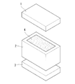
- a molding die in this embodiment is shown in FIG.
- the mold is composed of an upper mold 1, a middle mold 2, and a lower mold 3.
- the middle mold 2 has a cavity 4 inside, and a cavity is formed inside by joining the lower mold 3 and the upper mold 1 to the middle mold 2.
- a sealing member is disposed on the joint surface between the middle mold 2 and the lower mold 3 and the upper mold 1 so that the cavity is sealed when the middle mold 2 and the upper mold 1 and the lower mold 3 are joined. (Illustrated).
- a resin injection line and a suction line (not shown) are connected to the mold so as to communicate with the cavity. The resin injection line and the suction line are arranged so that the resin flows in the thickness direction of the reinforcing fiber substrate when the reinforcing fiber substrate is arranged in the mold.
- FIG. 2 shows an arrangement example of the heating control unit according to the present embodiment.
- the heating control unit includes a lower mold heating control unit 5 and an upper mold heating control unit 6.
- the heating control unit in the present embodiment is a heating plate capable of raising the temperature in a desired range by contacting the mold.
- the heating control unit is not limited to this, and may be embedded in a mold.
- the heating control unit may be arranged so as to heat only the portion containing the reinforcing fiber base material in order to prevent the heat from going around the mold.
- a heating control plate 7 made of a plate (for example, an aluminum alloy) for controlling heat transfer between the heating plate on the side to be heated first (high temperature side) and the mold. It is good to intervene.
- the method for controlling the amount of heat transfer is not limited to the above.
- the lower mold heating control unit 5 includes a lower mold heat source for raising the temperature of the lower mold 3 and can control the heating temperature of the lower mold heat source.
- the heat source for the lower mold may be singular or plural, and the surface facing the cavity direction of the lower mold 3 can be heated substantially uniformly.
- a plurality of heaters are embedded in the lower mold heating control unit 5 at intervals.
- the upper mold heating control unit 6 includes an upper mold heat source for raising the temperature of the upper mold 1 and can control the heating temperature of the upper mold heat source.
- the upper mold heat source may be singular or plural, and the surface of the upper mold 1 facing the cavity direction can be heated substantially uniformly.
- a plurality of heaters are embedded in the upper mold heating control unit 6 at intervals.
- each lower mold heat source may be individually controllable.
- the heating temperature of each upper mold heat source may be individually controllable. Thereby, it is possible to form a temperature difference not only in the thickness direction of the reinforcing fiber base 8 but also in the in-plane direction.
- an intermediate medium is disposed between the mold and the reinforcing fiber substrate 8 when the reinforcing fiber substrate 8 is disposed in the cavity.
- the intermediate medium is between the lower mold 3 and the reinforcing fiber substrate 8, between the upper mold 1 and the reinforcing fiber substrate 8, or between the lower mold 3 and the reinforcing fiber substrate 8, and between the upper mold 1 and the reinforcing fiber substrate 8. It may be disposed both between the substrate 8.
- the type and size of the intermediate medium are selected as appropriate.
- a perforated plate or a perforated film can be used as the intermediate medium.
- FIG. 3 shows an arrangement example of the intermediate medium. For simplification of explanation, description of the lower mold and the upper mold is omitted.
- the intermediate medium 9 is preferably disposed so as to be shifted from each other on both the resin injection part 10 side and the resin discharge part 11 side of the reinforcing fiber base 8.
- the intermediate medium 9 arranged on the resin injection part 10 side has a larger area than the intermediate medium 9 arranged on the resin discharge part 11 side. By doing so, it becomes easy to diffuse the resin injected into the cavity from the resin injection line 12 in the surface direction of the reinforcing fiber base 8.
- the reinforcing fiber substrate used in this embodiment is carbon fiber, glass fiber, aramid fiber, metal fiber, boron fiber, alumina fiber, silicon carbide high-strength synthetic fiber, etc., and carbon fiber is particularly preferable.
- the resin used in this embodiment is a thermosetting resin, such as an epoxy resin.
- a thermosetting resin such as an epoxy resin.
- a phenol resin, polyimide resin, bismaleimide resin, benzoxazine resin, or the like that contains a large amount of volatile components that are difficult to form by conventional RTM can also be used.
- FIG. 4 shows the relationship between time and viscosity / temperature in a thermosetting resin.
- the horizontal axis represents time
- the vertical axis represents viscosity / temperature
- the broken line represents the viscosity profile
- the solid line represents the temperature profile.
- the thermosetting resin once decreases in viscosity by heating, and when a predetermined heating condition is reached, the three-dimensional crosslinking reaction proceeds and the viscosity increases.
- the thermosetting resin is preliminarily heated to be in a low viscosity state that can be impregnated into the reinforcing fiber base material, and then injected into the cavity. Heating conditions are set
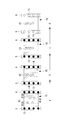
- FIG. 5 is a diagram illustrating the steps of the RTM molding method according to this embodiment.
- the reinforcing fiber base material is disposed in the cavity and then clamped.
- suction is performed from the suction line, and the pressure in the cavity is reduced.
- the mold is heated so that the thermosetting resin used can maintain a low viscosity state for a long time.
- the thermosetting resin is vacuum impregnated and pressurized into the cavity through the resin injection line, and impregnated in the thickness direction of the reinforcing fiber base.
- the resin suction is stopped after impregnating the whole of the reinforcing fiber base material with the thermosetting resin.
- the pressurization of the resin is preferably continued.
- the RTM molding method includes a first temperature raising step and a second temperature raising step in order to cure the thermosetting resin.
- first temperature raising step first, only one of the lower mold and the upper mold is heated at a predetermined rate by the heating control unit.
- the heating control unit In the present embodiment, it is assumed that the lower mold is heated by the lower mold heating control unit to raise the temperature.
- FIG. 6 is a schematic diagram for explaining how the thermosetting resin is cured by the RTM molding method according to this embodiment.
- the description of the mold is omitted for simplification of the drawing.
- the temperature difference is appropriately set according to the type of the thermosetting resin used, the heating profile of the lower mold heat source 13, the thickness of the reinforcing fiber substrate, the fiber density of the reinforcing fiber substrate, and the like.
- the temperature difference is preferably a predetermined value or more.
- the predetermined value is a temperature difference when the heat generated by the lower mold heat source 13 is transmitted to the upper mold heating control side of the reinforcing fiber base 16 including the thermosetting resin.
- the upper die heating control unit 6 After forming the temperature gradient, as the second temperature raising step, the upper die heating control unit 6 starts raising the upper die (C in FIG. 6).
- the upper mold heating control unit 6 controls the temperature of the upper mold heat source 14 so as not to be higher than the temperature of the lower mold heating control unit 5.
- the lower mold and the upper mold are finally heated up to the curing holding temperature of the resin, and the curing holding temperature is held for a predetermined time (D in FIG. 6). Thereafter, heating by each heat source is stopped (E in FIG. 6).
- thermosetting resin on the higher temperature side has a higher viscosity
- thermosetting resin on the lower temperature side has a lower viscosity.
- Bubbles 15 in the thermosetting resin are generated at a low viscosity. Further, the bubbles 15 contained in the thermosetting resin 16 impregnated in the reinforcing fiber base and the volatile components 15 generated by heating for the curing reaction are stabilized as the resin viscosity increases on the lower mold side. It moves to the low viscosity side that can exist. Or it occurs in the low viscosity region.
- the resin shrinkage when the resin is cured moves to the low viscosity side (uncured side).
- the resin shrinkage can be collected on the upper mold side in the mold. Therefore, even a thick plate member having a plate thickness of 10 mm or more can be RTM-molded without generating voids and porosity therein while ensuring plate thickness accuracy.
- the reinforcing fiber base is thick, when the mold is heated by the heating controller, heat is used to heat the resin and the mold is cooled by heat transfer to the atmosphere. Even without a cooling structure, a temperature gradient can be formed in the thickness direction of the reinforcing fiber substrate.
- the mold may be clamped after an intermediate member is disposed between the mold and the reinforcing fiber substrate.
- an intermediate member is disposed between the upper mold and the reinforcing fiber base, voids and porosity can be collected in the intermediate member.
- a 2 inch (50.4 mm) thick reinforcing fiber base made of carbon fiber is placed in the cavity, and impregnated with an epoxy resin from the upper mold side in the thickness direction of the reinforcing fiber base I let you.
- the reinforcing fiber base and the epoxy resin are present in a ratio of 55% by volume and 45% by volume, respectively.
- FIG. 7 shows a temperature profile during RTM molding according to this example.
- the horizontal axis represents time
- the vertical axis represents temperature
- the solid line represents the lower mold temperature profile
- the broken line represents the upper mold temperature profile.
- the temperature of the molds (lower mold, middle mold and upper mold) during resin impregnation was 110 ° C.
- the lower mold was heated and heated by raising the temperature of the lower mold heat source at 0.5 ° C./min by the lower mold heating controller.
- the lower mold was heated to a curing holding temperature of 185 ° C.
- the upper die also reached 185 ° C., and after maintaining the temperature for 2 hours, the heating was stopped.
- the upper mold heat control unit sets the upper mold heat source at a lower temperature rise rate of 0.38 ° C./min.
- the temperature was increased by heating.
- the upper mold was heated to a curing holding temperature of 185 ° C. to maintain the temperature, and then the heating was stopped simultaneously with the lower mold.
- time A the temperature near the lower mold heat source (T1) is raised, the temperature far from the lower mold heat source (T3), and the central area (T2) between T1 and T3 are heated.
- time C when the temperature of the lower mold is raised to 35 ° C. (time C), heat is transferred from the lower mold side to the upper mold side, and the entire reinforcing fiber base impregnated with the resin is heated. At this time, a temperature gradient is formed from T1 to T3, and the temperature has a relationship of t1> t2> t3.
- thermosetting resin exceeds a predetermined heating condition
- the cross-linking reaction proceeds and the viscosity increases, so the viscosity of the resin increases from the portion close to the lower mold heat source. Bubbles, volatile components, and resin shrinkage move to the low viscosity side as the resin temperature rises.
- the temperatures from T1 to T3 during RTM molding were measured.
- Thermocouples were installed on the lower mold side (T1), the central part (T2), and the upper mold side (T3) in the reinforcing fiber base, and the temperature during RTM molding was measured.
- the results are shown in FIG.
- the horizontal axis represents time and the vertical axis represents temperature.
- the temperature rise of the lower mold was started, and the temperature rise of the upper mold was started at 70 minutes.
- the temperature of the lower mold is raised by 35 ° C. and then the upper mold is heated, so that the reinforcing fiber base material including the resin is in the plate thickness direction (T1 to T3) until the upper mold reaches the curing holding temperature. ), It was confirmed that a temperature gradient was always formed.
- FIG. 9 is a schematic diagram for explaining how the thermosetting resin is cured by the RTM molding method according to the comparative example.
- the central part is heated most lastly. Therefore, since bubbles, volatile components, and resin shrinkage are likely to collect in the central portion, voids and porosity derived from the bubbles and volatile components are generated inside after the curing cycle.
Landscapes
- Engineering & Computer Science (AREA)
- Mechanical Engineering (AREA)
- Chemical & Material Sciences (AREA)
- Composite Materials (AREA)
- Physics & Mathematics (AREA)
- Health & Medical Sciences (AREA)
- Oral & Maxillofacial Surgery (AREA)
- Thermal Sciences (AREA)
- Manufacturing & Machinery (AREA)
- Casting Or Compression Moulding Of Plastics Or The Like (AREA)
- Moulding By Coating Moulds (AREA)
- Reinforced Plastic Materials (AREA)
Abstract
La présente invention concerne un procédé de moulage d'un article moulé dans lequel la surface et l'intérieur ne présentent aucun vide, aucune porosité ni aucun rétrécissement de résine tout en maintenant la précision d'épaisseur de feuille même avec un élément de feuille épaisse présentant une épaisseur égale ou supérieure à 10 mm. Un procédé de moulage par transfert de résine comprend : une première étape de chauffage permettant d'imprégner, avec une résine thermoplastique, un substrat de fibre de renforcement disposé à l'intérieur d'une matrice de moulage composée de deux ou plus de deux éléments de matrice distincts puis de chauffage de l'un quelconque des éléments de matrice composant la matrice de moulage afin de former un gradient de température présentant une différence de température égale ou supérieure à une valeur prédéterminée depuis un côté du substrat de fibre de renforcement vers l'autre côté ; et une seconde étape de chauffage permettant de chauffer un autre élément de matrice qui est différent de l'élément de matrice chauffé dans la première étape de chauffage.
Priority Applications (3)
| Application Number | Priority Date | Filing Date | Title |
|---|---|---|---|
| US14/117,497 US20140070452A1 (en) | 2011-05-16 | 2012-03-15 | Rtm method and rtm apparatus |
| CA2836015A CA2836015C (fr) | 2011-05-16 | 2012-03-15 | Methode de moulage de transfert de resine et appareil de moulage de resine |
| EP20120785535 EP2711154A4 (fr) | 2011-05-16 | 2012-03-15 | Procédé de moulage par transfert de résine et dispositif de moulage par transfert de résine |
Applications Claiming Priority (2)
| Application Number | Priority Date | Filing Date | Title |
|---|---|---|---|
| JP2011109670A JP5791365B2 (ja) | 2011-05-16 | 2011-05-16 | Rtm成形方法及びrtm成形装置 |
| JP2011-109670 | 2011-05-16 |
Publications (1)
| Publication Number | Publication Date |
|---|---|
| WO2012157327A1 true WO2012157327A1 (fr) | 2012-11-22 |
Family
ID=47176669
Family Applications (1)
| Application Number | Title | Priority Date | Filing Date |
|---|---|---|---|
| PCT/JP2012/056696 Ceased WO2012157327A1 (fr) | 2011-05-16 | 2012-03-15 | Procédé de moulage par transfert de résine et dispositif de moulage par transfert de résine |
Country Status (5)
| Country | Link |
|---|---|
| US (1) | US20140070452A1 (fr) |
| EP (1) | EP2711154A4 (fr) |
| JP (1) | JP5791365B2 (fr) |
| CA (1) | CA2836015C (fr) |
| WO (1) | WO2012157327A1 (fr) |
Cited By (1)
| Publication number | Priority date | Publication date | Assignee | Title |
|---|---|---|---|---|
| JP2018140595A (ja) * | 2017-02-28 | 2018-09-13 | 株式会社Subaru | 繊維強化複合材料の製造方法 |
Families Citing this family (3)
| Publication number | Priority date | Publication date | Assignee | Title |
|---|---|---|---|---|
| CN105829046B (zh) * | 2014-01-17 | 2018-05-04 | 东丽株式会社 | 被覆纤维增强树脂成型品及其制造方法 |
| US11001011B2 (en) * | 2016-02-23 | 2021-05-11 | Toray Industries, Inc. | Method of producing fiber reinforced composite material |
| JP6715226B2 (ja) | 2017-10-25 | 2020-07-01 | 株式会社Subaru | 複合材成形治具及び複合材成形方法 |
Citations (4)
| Publication number | Priority date | Publication date | Assignee | Title |
|---|---|---|---|---|
| JPH04144723A (ja) * | 1990-10-08 | 1992-05-19 | Mitsubishi Kasei Corp | 繊維強化樹脂成形体の製造方法 |
| JP2003025346A (ja) * | 2001-07-16 | 2003-01-29 | Toray Ind Inc | Rtm成形方法 |
| JP3421101B2 (ja) | 1993-12-09 | 2003-06-30 | 富士重工業株式会社 | 複合材の成形装置 |
| JP2005246902A (ja) * | 2004-03-08 | 2005-09-15 | Toray Ind Inc | Rtm成形方法 |
Family Cites Families (5)
| Publication number | Priority date | Publication date | Assignee | Title |
|---|---|---|---|---|
| US4784814A (en) * | 1985-07-11 | 1988-11-15 | Ciba-Geigy Corporation | Pressure reaction injection molding process for making molded bodies of thermosets optionally containing filler and/or reinforcing material |
| US5052906A (en) * | 1989-03-30 | 1991-10-01 | Seemann Composite Systems, Inc. | Plastic transfer molding apparatus for the production of fiber reinforced plastic structures |
| JP2781354B2 (ja) * | 1994-12-28 | 1998-07-30 | 日本碍子株式会社 | 加熱冷却機構付きセグメントおよびそれを用いた金型 |
| FR2740382B1 (fr) * | 1995-10-25 | 1997-12-05 | Snecma | Procede de moulage de pieces allongees a haute resistance en composite fibre-resine |
| DE102008014657B4 (de) * | 2008-03-17 | 2015-08-20 | Airbus Defence and Space GmbH | Verfahren zur Herstellung von Faserverbundbauteilen |
-
2011
- 2011-05-16 JP JP2011109670A patent/JP5791365B2/ja active Active
-
2012
- 2012-03-15 EP EP20120785535 patent/EP2711154A4/fr not_active Withdrawn
- 2012-03-15 US US14/117,497 patent/US20140070452A1/en not_active Abandoned
- 2012-03-15 WO PCT/JP2012/056696 patent/WO2012157327A1/fr not_active Ceased
- 2012-03-15 CA CA2836015A patent/CA2836015C/fr not_active Expired - Fee Related
Patent Citations (4)
| Publication number | Priority date | Publication date | Assignee | Title |
|---|---|---|---|---|
| JPH04144723A (ja) * | 1990-10-08 | 1992-05-19 | Mitsubishi Kasei Corp | 繊維強化樹脂成形体の製造方法 |
| JP3421101B2 (ja) | 1993-12-09 | 2003-06-30 | 富士重工業株式会社 | 複合材の成形装置 |
| JP2003025346A (ja) * | 2001-07-16 | 2003-01-29 | Toray Ind Inc | Rtm成形方法 |
| JP2005246902A (ja) * | 2004-03-08 | 2005-09-15 | Toray Ind Inc | Rtm成形方法 |
Non-Patent Citations (1)
| Title |
|---|
| See also references of EP2711154A4 |
Cited By (2)
| Publication number | Priority date | Publication date | Assignee | Title |
|---|---|---|---|---|
| JP2018140595A (ja) * | 2017-02-28 | 2018-09-13 | 株式会社Subaru | 繊維強化複合材料の製造方法 |
| US11167452B2 (en) | 2017-02-28 | 2021-11-09 | Subaru Corporation | Method of manufacturing fiber-reinforced composite material |
Also Published As
| Publication number | Publication date |
|---|---|
| EP2711154A4 (fr) | 2015-03-04 |
| CA2836015C (fr) | 2016-10-04 |
| CA2836015A1 (fr) | 2012-11-22 |
| EP2711154A1 (fr) | 2014-03-26 |
| JP5791365B2 (ja) | 2015-10-07 |
| US20140070452A1 (en) | 2014-03-13 |
| JP2012240231A (ja) | 2012-12-10 |
Similar Documents
| Publication | Publication Date | Title |
|---|---|---|
| CA2662476C (fr) | Outil et procede de formation d'outils de moulage pour produire des preformes et des plastiques renforces de fibres avec l'outil | |
| JP6557972B2 (ja) | 繊維強化プラスチックの製造方法および製造装置 | |
| CN101489768A (zh) | 制造复合部件的方法 | |
| EP3702155B1 (fr) | Procédé de préparation d'un produit composite et produit composite | |
| JP6750735B2 (ja) | 複合材料の成形方法および複合材料の成形装置 | |
| WO2000054949A2 (fr) | Appareil d'outillage chauffe et procede de traitement de materiau composite et plastique | |
| JP5791365B2 (ja) | Rtm成形方法及びrtm成形装置 | |
| US12179442B2 (en) | Method for forming a fibre article | |
| JP2020526414A (ja) | 製織された繊維プリフォームに樹脂を注入することによって部品を製造するための方法および装置 | |
| JP6384213B2 (ja) | 複合材料の製造方法、複合材料の製造装置 | |
| CN114599505B (zh) | 用于由纤维复合材料生产构件的方法 | |
| US12343947B2 (en) | Method for producing composite molded body | |
| KR20220092400A (ko) | 탄소섬유복합재 부품의 제조방법 및 제조장치 | |
| KR101447136B1 (ko) | 섬유 강화 복합재의 성형방법 | |
| US20070120288A1 (en) | System, method, and apparatus for production-worthy, low cost composite tool fabrication | |
| WO2020246622A1 (fr) | Procédé de fabrication d'un article moulé en résine renforcée par des fibres thermoplastiques | |
| JPWO2017061146A1 (ja) | 繊維強化複合部材の成形装置 | |
| JP2016135575A (ja) | 複合材料の成形方法および成形装置 | |
| KR20210081791A (ko) | 복합재 제작용 프리폼 성형 장치 및 복합재 제작용 프리폼 성형 방법 | |
| RU2742301C1 (ru) | Способ изготовления модельной оснастки для формования изделий из полимерных композиционных материалов (варианты) | |
| RU2496640C1 (ru) | Способ изготовления изделия из полимерного композиционного материала трансферно-мембранным формованием "тмф" (варианты) | |
| JP2025506300A (ja) | 湾曲パネルのための鋳型 | |
| KR20240003220A (ko) | 기공도가 낮은 복합 소재 제조방법 | |
| KR20130069944A (ko) | 섬유 강화 복합재의 성형 방법 | |
| JP2017105062A (ja) | 繊維強化プラスチック製造装置および製造方法 |
Legal Events
| Date | Code | Title | Description |
|---|---|---|---|
| 121 | Ep: the epo has been informed by wipo that ep was designated in this application |
Ref document number: 12785535 Country of ref document: EP Kind code of ref document: A1 |
|
| ENP | Entry into the national phase |
Ref document number: 2836015 Country of ref document: CA |
|
| WWE | Wipo information: entry into national phase |
Ref document number: 14117497 Country of ref document: US |
|
| WWE | Wipo information: entry into national phase |
Ref document number: 2012785535 Country of ref document: EP |
|
| NENP | Non-entry into the national phase |
Ref country code: DE |