WO2012157424A1 - Procédé de régénération de filtre en nid d'abeilles - Google Patents
Procédé de régénération de filtre en nid d'abeilles Download PDFInfo
- Publication number
- WO2012157424A1 WO2012157424A1 PCT/JP2012/061128 JP2012061128W WO2012157424A1 WO 2012157424 A1 WO2012157424 A1 WO 2012157424A1 JP 2012061128 W JP2012061128 W JP 2012061128W WO 2012157424 A1 WO2012157424 A1 WO 2012157424A1
- Authority
- WO
- WIPO (PCT)
- Prior art keywords
- flow path
- honeycomb filter
- temperature
- channel
- regeneration
- Prior art date
- Legal status (The legal status is an assumption and is not a legal conclusion. Google has not performed a legal analysis and makes no representation as to the accuracy of the status listed.)
- Ceased
Links
Images


Classifications
-
- B—PERFORMING OPERATIONS; TRANSPORTING
- B01—PHYSICAL OR CHEMICAL PROCESSES OR APPARATUS IN GENERAL
- B01D—SEPARATION
- B01D46/00—Filters or filtering processes specially modified for separating dispersed particles from gases or vapours
- B01D46/42—Auxiliary equipment or operation thereof
-
- B—PERFORMING OPERATIONS; TRANSPORTING
- B01—PHYSICAL OR CHEMICAL PROCESSES OR APPARATUS IN GENERAL
- B01D—SEPARATION
- B01D46/00—Filters or filtering processes specially modified for separating dispersed particles from gases or vapours
- B01D46/42—Auxiliary equipment or operation thereof
- B01D46/44—Auxiliary equipment or operation thereof controlling filtration
- B01D46/448—Auxiliary equipment or operation thereof controlling filtration by temperature measuring
-
- B—PERFORMING OPERATIONS; TRANSPORTING
- B01—PHYSICAL OR CHEMICAL PROCESSES OR APPARATUS IN GENERAL
- B01D—SEPARATION
- B01D46/00—Filters or filtering processes specially modified for separating dispersed particles from gases or vapours
- B01D46/66—Regeneration of the filtering material or filter elements inside the filter
- B01D46/80—Chemical processes for the removal of the retained particles, e.g. by burning
- B01D46/84—Chemical processes for the removal of the retained particles, e.g. by burning by heating only
-
- F—MECHANICAL ENGINEERING; LIGHTING; HEATING; WEAPONS; BLASTING
- F01—MACHINES OR ENGINES IN GENERAL; ENGINE PLANTS IN GENERAL; STEAM ENGINES
- F01N—GAS-FLOW SILENCERS OR EXHAUST APPARATUS FOR MACHINES OR ENGINES IN GENERAL; GAS-FLOW SILENCERS OR EXHAUST APPARATUS FOR INTERNAL-COMBUSTION ENGINES
- F01N3/00—Exhaust or silencing apparatus having means for purifying, rendering innocuous, or otherwise treating exhaust
- F01N3/02—Exhaust or silencing apparatus having means for purifying, rendering innocuous, or otherwise treating exhaust for cooling, or for removing solid constituents of, exhaust
- F01N3/021—Exhaust or silencing apparatus having means for purifying, rendering innocuous, or otherwise treating exhaust for cooling, or for removing solid constituents of, exhaust by means of filters
- F01N3/022—Exhaust or silencing apparatus having means for purifying, rendering innocuous, or otherwise treating exhaust for cooling, or for removing solid constituents of, exhaust by means of filters characterised by specially adapted filtering structure, e.g. honeycomb, mesh or fibrous
- F01N3/0222—Exhaust or silencing apparatus having means for purifying, rendering innocuous, or otherwise treating exhaust for cooling, or for removing solid constituents of, exhaust by means of filters characterised by specially adapted filtering structure, e.g. honeycomb, mesh or fibrous the structure being monolithic, e.g. honeycombs
-
- B—PERFORMING OPERATIONS; TRANSPORTING
- B01—PHYSICAL OR CHEMICAL PROCESSES OR APPARATUS IN GENERAL
- B01D—SEPARATION
- B01D46/00—Filters or filtering processes specially modified for separating dispersed particles from gases or vapours
- B01D46/24—Particle separators, e.g. dust precipitators, using rigid hollow filter bodies
- B01D46/2403—Particle separators, e.g. dust precipitators, using rigid hollow filter bodies characterised by the physical shape or structure of the filtering element
- B01D46/2418—Honeycomb filters
- B01D46/2451—Honeycomb filters characterized by the geometrical structure, shape, pattern or configuration or parameters related to the geometry of the structure
- B01D46/247—Honeycomb filters characterized by the geometrical structure, shape, pattern or configuration or parameters related to the geometry of the structure of the cells
-
- F—MECHANICAL ENGINEERING; LIGHTING; HEATING; WEAPONS; BLASTING
- F01—MACHINES OR ENGINES IN GENERAL; ENGINE PLANTS IN GENERAL; STEAM ENGINES
- F01N—GAS-FLOW SILENCERS OR EXHAUST APPARATUS FOR MACHINES OR ENGINES IN GENERAL; GAS-FLOW SILENCERS OR EXHAUST APPARATUS FOR INTERNAL-COMBUSTION ENGINES
- F01N2330/00—Structure of catalyst support or particle filter
- F01N2330/30—Honeycomb supports characterised by their structural details
- F01N2330/34—Honeycomb supports characterised by their structural details with flow channels of polygonal cross section
-
- Y—GENERAL TAGGING OF NEW TECHNOLOGICAL DEVELOPMENTS; GENERAL TAGGING OF CROSS-SECTIONAL TECHNOLOGIES SPANNING OVER SEVERAL SECTIONS OF THE IPC; TECHNICAL SUBJECTS COVERED BY FORMER USPC CROSS-REFERENCE ART COLLECTIONS [XRACs] AND DIGESTS
- Y02—TECHNOLOGIES OR APPLICATIONS FOR MITIGATION OR ADAPTATION AGAINST CLIMATE CHANGE
- Y02T—CLIMATE CHANGE MITIGATION TECHNOLOGIES RELATED TO TRANSPORTATION
- Y02T10/00—Road transport of goods or passengers
- Y02T10/10—Internal combustion engine [ICE] based vehicles
- Y02T10/12—Improving ICE efficiencies
Definitions
- the present invention relates to a method for regenerating a honeycomb filter.
- the honeycomb filter is used as a ceramic filter for removing the collected matter from the fluid containing the collected matter, for example, for purifying exhaust gas exhausted from an internal combustion engine such as a diesel engine or a gasoline engine. Used as an exhaust gas filter.
- a honeycomb filter has a plurality of parallel flow paths partitioned by porous partition walls (see, for example, Patent Document 1 below).
- the collected matter is deposited on the surface of the partition wall or inside the partition wall in the honeycomb filter.
- the collected material is excessively accumulated in the honeycomb filter, the movement of the fluid in the honeycomb filter is hindered and the purification performance of the honeycomb filter is deteriorated. Therefore, after depositing a certain amount of collected material in the honeycomb filter, combustion regeneration of the honeycomb filter is performed in order to burn and remove the collected material as a substance to be removed.
- the honeycomb filter may be thermally damaged or melted. Therefore, for the regeneration method of the honeycomb filter, it is required to reduce the thermal stress generated in the combustion regeneration.
- the present invention has been made in view of such circumstances, and an object of the present invention is to provide a method for regenerating a honeycomb filter capable of reducing thermal stress generated in combustion regeneration.
- a method for regenerating a honeycomb filter according to the present invention is a method for regenerating a honeycomb filter having a plurality of parallel flow paths partitioned by porous partition walls, and increases the temperature in the flow path where the substance to be removed is deposited.
- a regeneration step of burning the material to be removed, and an absolute value of the amount of change in temperature per unit time in the regeneration step is 35 at a predetermined position in the honeycomb filter that reaches the maximum temperature in the honeycomb filter in the regeneration step. C / sec or less.
- an excessive thermal stress may be applied to the honeycomb filter due to a sudden change in the temperature of the honeycomb filter.
- the amount of change in temperature at the position of the honeycomb filter that reaches the maximum temperature in the honeycomb filter in the regeneration process affects the magnitude of thermal stress.
- the thermal stress generated in the combustion regeneration can be reduced.
- the partition preferably contains aluminum titanate. In this case, the thermal stress generated in the combustion regeneration can be further reduced.
- the plurality of flow paths include a first flow path and a plurality of second flow paths adjacent to the first flow path.
- the second channel and the other second channel are adjacent to each other, the end of one end of the honeycomb filter in the first channel is sealed, and the honeycomb filter in the second channel is sealed.
- the end portion on the other end side is sealed, and the cross section of the second flow path perpendicular to the axial direction of the second flow path is disposed on each of the first side and both sides of the first side.
- the second side of the second flow path may be opposed to the second side of the adjacent second flow path.
- the absolute value of the amount of change in temperature per unit time at the predetermined position when the temperature at the predetermined position decreases in the regeneration step is preferably 30 ° C./second or less. In this case, the thermal stress generated in the combustion regeneration can be further reduced.
- the maximum temperature may be 800 to 1250 ° C.
- the temperature in the flow path where the removal target substance is deposited may be raised by the combustion heat of the fuel.
- the method for regenerating a honeycomb filter according to the present invention can reduce the thermal stress generated in the honeycomb filter during combustion regeneration. Thereby, it is possible to prevent the honeycomb filter from being thermally damaged or melted during combustion regeneration.
- FIG. 1 is a drawing schematically showing a honeycomb filter used in a regeneration method according to an embodiment of the present invention.
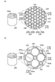
- FIG. 2 is a drawing schematically showing another honeycomb filter used in the regeneration method according to an embodiment of the present invention.
- FIG. 3 is a drawing showing the measurement result of the temperature at a predetermined position in the honeycomb filter.
- FIG. 1 is a drawing schematically showing a honeycomb filter used in the regeneration method according to the present embodiment.
- the honeycomb filter 100 is a cylindrical body having a plurality of flow paths 110 arranged substantially parallel to each other.
- the plurality of flow paths 110 are partitioned by partition walls 120 that extend substantially parallel to the central axis of the honeycomb filter 100.
- the plurality of channels 110 includes a plurality of channels (first channels) 110a and a plurality of channels (second channels) 110b adjacent to the channels 110a.
- the flow path 110 a and the flow path 110 b extend substantially perpendicular to both end faces of the honeycomb filter 100.
- One end of the flow path 110a constituting a part of the flow path 110 is sealed by the sealing portion 130 on the one end face 100a of the honeycomb filter 100, and the other end of the flow path 110a is the other end face 100b of the honeycomb filter 100. Is open.
- one end of the flow path 110b that constitutes the remaining part of the plurality of flow paths 110 is open at the one end face 100a, and the other end of the flow path 110b is sealed by the sealing portion 130 at the other end face 100b.
- the end on the one end face 100a side of the flow path 110b is opened as a gas inlet
- the end on the other end face 100b side of the flow path 110a is opened as a gas outlet.
- the cross section substantially perpendicular to the axial direction (longitudinal direction) of the flow path 110a and the flow path 110b has a hexagonal shape.
- the cross section of the channel 110a is preferably a regular hexagon in which the lengths of the sides 140 forming the cross section are substantially equal to each other, but may be a flat hexagon.
- the cross section of the channel 110b is, for example, a flat hexagonal shape, but may be a regular hexagonal shape.
- the lengths of the sides facing each other in the cross section of the channel 110b are substantially equal to each other.
- the cross section of the channel 110b has two long sides (first side) 150a having approximately the same length as the side 150 forming the cross section, and four (two pairs) having substantially the same length. ) Short side (second side) 150b.
- the short side 150b is disposed on each side of the long side 150a.
- the long sides 150a face each other substantially in parallel, and the short sides 150b face each other substantially in parallel.
- the channel 110a is alternately arranged with the channel 110b in the arrangement direction of the channels 110a (a direction substantially orthogonal to the side 140) by arranging one channel 110b between the adjacent channels 110a. Yes.
- Each of the sides 140 of the flow path 110a is opposed to the long side 150a of any one of the plurality of flow paths 110b substantially in parallel. That is, the flow path 110 has a structural unit including one flow path 110a and six flow paths 110b surrounding the flow path 110a, and in the structural unit, all the sides 140 of the flow path 110a are included. It faces the long side 150a of the flow path 110b.
- Each of the short sides 150b of the flow path 110b is opposed substantially parallel to the short side 150b of the adjacent flow path 110b.
- the length of the honeycomb filter 100 in the longitudinal direction of the flow paths 110a and 110b is, for example, 50 to 300 mm.
- the outer diameter of the honeycomb filter 100 is, for example, 50 to 250 mm.
- the density (cell density) of the channels 110a and 110b is, for example, 50 to 400 cpsi (cell per square inch). “Cpsi” represents the number of flow paths (cells) per square inch.
- the total area of the gas inflow side flow paths is preferably larger than the total area of the gas outflow side flow paths, that is, the total of the flow paths 110b.
- the area is preferably larger than the total area of the flow paths 110a.
- the length of the side 140 is, for example, 0.2 to 2.0 mm
- the length of the long side 150a is, for example, 0.4
- the length of the short side 150b is, for example, 0.3 to 2.0 mm.
- the thickness (cell wall thickness) of the partition wall 120 in the structural unit is, for example, 0.1 to 0.8 mm.
- the porosity of the partition wall 120 in the structural unit is, for example, 20 to 60% by volume.
- the pore diameter (pore diameter) of the partition wall 120 in the structural unit is, for example, 5 to 30 ⁇ m.
- the partition wall 120 is porous, and includes, for example, porous ceramics (porous ceramic sintered body).
- the partition wall 120 has a structure that allows fluid (for example, exhaust gas containing fine particles such as soot) to pass therethrough. Specifically, many communication holes (flow channels) through which fluid can pass are formed in the partition wall 120.
- the partition wall 120 preferably contains aluminum titanate, and may further contain magnesium or silicon.
- the partition 120 is made of, for example, porous ceramics mainly made of an aluminum titanate crystal. “Mainly composed of an aluminum titanate-based crystal” means that the main crystal phase constituting the aluminum titanate-based ceramic fired body is an aluminum titanate-based crystal phase. An aluminum titanate crystal phase, an aluminum magnesium titanate crystal phase, or the like may be used.
- the partition 120 may include a phase (crystal phase) other than the aluminum titanate crystal phase or the glass phase. Examples of the phase other than the aluminum titanate-based crystal phase include a phase derived from a raw material used for producing an aluminum titanate-based ceramic fired body.
- the honeycomb filter 100 can be manufactured by a known method.
- the manufacturing method of the honeycomb filter 100 includes: (a) a raw material preparation step of preparing a raw material mixture containing ceramic powder and a pore-forming agent; and (b) forming a raw material mixture to obtain a formed body having a flow path. And (c) a firing step for firing the molded body, and (d) a sealing step for sealing one end of each flow path between the molding step and the firing step or after the firing step.
- the honeycomb filter 100 is suitable as a particulate filter that collects PM (Particulate Matter) such as soot contained in exhaust gas from an internal combustion engine such as a diesel engine or a gasoline engine as a collection target.
- PM Porate Matter
- the honeycomb filter 100 is disposed in the exhaust passage of the internal combustion engine.
- the gas G supplied from the one end face 100a to the flow path 110b passes through the communication hole in the partition wall 120 and reaches the adjacent flow path 110a. It is discharged from 100b.
- the collected matter in the gas G is collected on the surface of the partition wall 120 or in the communication hole and removed from the gas G, whereby the honeycomb filter 100 functions as a filter.
- the regeneration method of the honeycomb filter according to the present embodiment includes, for example, a preparation step of preparing the honeycomb filter, and a regeneration step of increasing the temperature in the flow path in which the removal target substance is accumulated and burning the removal target substance. .
- a honeycomb filter having a flow path in which a substance to be removed is accumulated is prepared. And the flow path (for example, flow path 110b in FIG. 1) on the gas inflow side of the honeycomb filter is connected to the exhaust pipe of the internal combustion engine.
- the regeneration process includes, for example, a temperature raising process in which the temperature in the honeycomb filter increases and a temperature lowering process in which the temperature in the honeycomb filter decreases.
- the temperature raising method in the temperature raising step is not particularly limited, and the temperature in the honeycomb filter is increased until reaching a temperature at which the removal target substance burns (for example, 630 ° C. or more when the removal target substance is PM). Any method can be used.
- the temperature raising method include a method in which the temperature in the flow path where the removal target substance is accumulated is raised by the combustion heat of fuel (for example, light oil).
- the fuel may be burned in the flow path, or a high-temperature gas obtained by burning outside the honeycomb filter may be supplied into the flow path. Further, the combustion of the fuel may be stopped when the temperature at which the removal target substance reaches the combustion temperature, and the fuel may continue to be burned thereafter. Even after the combustion of the fuel is stopped, the temperature in the honeycomb filter may be increased by the combustion heat generated by the combustion of the substance to be removed.
- the temperature raising method may be a method in which the temperature is directly increased by a heating device such as a heater.
- a supply gas containing a combustion-supporting gas such as oxygen gas can be supplied into the flow path.
- the supply gas may contain the fuel.
- the flow rate of the supply gas can be adjusted by the engine speed and torque of the internal combustion engine.
- the flow rate of the supply gas may be changed in the middle of the temperature raising process. For example, by reducing the flow rate of the supply gas when the temperature to be removed reaches the combustion temperature, the flow rate of the supply gas is compared with the temperature in the honeycomb filter. Thus, the low temperature supply gas may be prevented from flowing into the flow path.
- the maximum temperature recorded in the honeycomb filter may be 800 to 1250 ° C. because the substance to be removed can be sufficiently burned and removed, and the thermal stress generated in the combustion regeneration can be further reduced.
- the maximum temperature is preferably 900 ° C. or higher, more preferably 1000 ° C. or higher, from the viewpoint of further sufficiently removing the substance to be removed by combustion.
- the maximum temperature is preferably 1200 ° C. or less, and more preferably 1150 ° C. or less, from the viewpoint of further reducing the thermal stress generated in combustion regeneration.
- the temperature in the honeycomb filter gradually decreases in the temperature lowering process, and reaches the temperature of the supply gas (for example, 330 ° C.) or the temperature outside the honeycomb filter.
- the predetermined measurement in the honeycomb filter that reaches the maximum temperature in the honeycomb filter in the regeneration process is performed. Adjust the amount of change in position temperature to a low level. Specifically, at the measurement position, the absolute value of the amount of change in temperature per unit time in the regeneration process is 35 ° C./second or less. That is, when measuring the temporal change of the temperature distribution inside the honeycomb filter in the regeneration process, the expression “
- the amount of change in temperature per unit time at the measurement position when the temperature at the measurement position rises in the temperature raising step is preferably 32 ° C./second or less from the viewpoint of further reducing thermal stress.
- the amount of change in temperature per unit time at the measurement position when the temperature at the measurement position decreases in the temperature lowering step is preferably 30 ° C./second or less from the viewpoint of further reducing thermal stress, 25 More preferably, it is not more than ° C / second.
- the amount of change in temperature at the measurement position can be adjusted according to the conditions of the regeneration process (for example, the temperature of the supply gas and the amount of fuel supplied) and the structure of the honeycomb filter to be used.
- honeycomb filter 100 there are a plurality of channels adjacent to the first channel and the first channel.
- the second flow path, and one second flow path and the other second flow paths in the plurality of second flow paths are adjacent to each other, and in the first flow path,
- the end of one end of the honeycomb filter is sealed, the end of the other end of the honeycomb filter in the second channel is sealed, and the second flow perpendicular to the axial direction of the second channel is sealed.
- the cross section of the path has a first side and a second side disposed on both sides of the first side, and the first channel is perpendicular to the axial direction of the first channel.
- Each of the sides forming the cross section of the second channel is opposed to the first side of the second channel, and each of the second sides of the second channel is adjacent to the first channel. Faces the second side of the second channel, the filter is preferred.
- Examples of other filters having such a configuration include a honeycomb filter 200 shown in FIG. 2A and a honeycomb filter 300 shown in FIG. 2B.
- the honeycomb filter 200 is a cylindrical body having a plurality of flow paths 210 arranged substantially parallel to each other.
- the plurality of flow paths 210 are partitioned by partition walls 220 extending substantially parallel to the central axis of the honeycomb filter 200.
- the plurality of channels 210 include a plurality of channels (first channels) 210a and a plurality of channels (second channels) 210b adjacent to the channels 210a.
- the flow path 210 a and the flow path 210 b extend substantially perpendicular to both end faces of the honeycomb filter 200.
- One end of the flow path 210 a constituting a part of the flow path 210 is sealed by a sealing portion 230 at one end face of the honeycomb filter 200, and the other end of the flow path 210 a is opened at the other end face of the honeycomb filter 200. is doing.
- one end of the flow path 210b constituting the remaining part of the plurality of flow paths 210 is open at one end face of the honeycomb filter 200, and the other end of the flow path 210b is a sealing portion at the other end face of the honeycomb filter 200. 230 is sealed.
- the honeycomb filter 200 for example, an end on one end face side of the flow path 210b is opened as a gas inlet, and an end on the other end face side of the flow path 210a is opened as a gas outlet.
- the total area of the gas inflow side flow paths is preferably larger than the total area of the gas outflow side flow paths, that is, the total of the flow paths 210b.
- the area is preferably larger than the total area of the channels 210a.
- the cross section substantially perpendicular to the axial direction (longitudinal direction) of the flow path 210a and the flow path 210b is hexagonal.
- the cross section of the channel 210a is preferably a regular hexagonal shape in which the lengths of the sides 240 forming the cross section are substantially equal to each other, but may be a flat hexagonal shape.
- the cross section of the channel 210b is, for example, a flat hexagonal shape, but may be a regular hexagonal shape.
- the lengths of the sides facing each other in the cross section of the flow path 210b are different from each other.
- the cross section of the flow path 210b includes three long sides (first sides) 250a having substantially the same length as the sides 250 forming the cross section, and three short sides (second sides) having the substantially same length. ) 250b.
- the long side 250a and the short side 250b face each other substantially in parallel, and the short side 250b is disposed on each side of the long side 250a.
- the flow path 210 has a structural unit including one flow path 210a and six flow paths 210b surrounding the flow path 210a. In the structural unit, all of the sides 240 of the flow path 210a are included. It faces the long side 250a of the flow path 210b. Each of the short sides 250b of the flow path 210b is opposed to the short side 250b of the adjacent flow path 210b substantially in parallel.
- the honeycomb filter 300 has a plurality of flow paths 310 arranged substantially parallel to each other.
- the flow path 310 includes a plurality of flow paths (first flow paths) 310a and a plurality of flow paths (second flow paths) 310b adjacent to the flow paths 310a.
- One channel 310b and another channel 310b are adjacent to each other.
- One flow path 310b is disposed between the flow paths 310a adjacent to each other.
- An end portion on one end side of the honeycomb filter 300 in the flow path 310 a and an end portion on the other end side of the honeycomb filter 300 in the flow path 310 b are respectively sealed by a sealing portion 330.
- one end of the flow path 310b is opened as a gas inlet, and the other end of the flow path 310a is opened as a gas outlet.
- the total area of the gas inflow side flow paths is preferably larger than the total area of the gas outflow side flow paths, that is, the total of the flow paths 310b.
- the area is preferably larger than the total area of the flow path 310a.
- the flow path 310 is partitioned by a partition wall 320 that extends substantially parallel to the central axis of the honeycomb filter 300.
- the cross section substantially perpendicular to the axial direction of the flow path 310a is square, and the cross section substantially perpendicular to the axial direction of the flow path 310b is a regular octagon.
- the cross section of the flow path 310b perpendicular to the axial direction of the flow path 310b has a first side 350a and second sides 350b respectively disposed on both sides of the side 350a.
- the sides 350a face each other and the sides 350b face each other, and the lengths of the sides facing each other are equal to each other.
- Each of the sides 340 forming a cross section of the flow channel 310a perpendicular to the axial direction of the flow channel 310a faces the side 350a of any one of the plurality of flow channels 310b.
- Each of the sides 350b of the channel 310b faces the side 350b of the adjacent channel 310b.
- Example 1 Preparation of raw material mixture>
- a raw material mixture containing water (solvent) was prepared. The content of each component in the raw material mixture was adjusted to the following values.
- the above raw material mixture was kneaded and extruded.
- the cylindrical columnar body (DPF) which has a structure shown in FIG. 1 was produced by baking after sealing one edge part of each flow path of a molded object with a sealing material.
- the length of the columnar body in the longitudinal direction of the flow path (through hole) was 153 mm.
- the outer diameter of the end face of the columnar body was 144 mm.
- the density of the flow path (cell density) was 290 cpsi.
- the length of one side of the regular hexagonal channel was 0.9 mm.
- the length of the long side in the flat hexagonal channel was 0.9 mm, and the length of the short side was 0.6 mm.
- the thickness of the partition between flow paths was 12 mil (milli-inch, 0.30 mm).
- the porosity of the partition walls was 45% by volume.
- the pore diameter of the partition wall was 15 ⁇ m.
- Example 1 The same raw material mixture as in Example 1 was kneaded and then extruded. And the columnar body (DPF) by which the cross section with a square-shaped cross section was arranged in the grid
- the ends of the adjacent flow paths were alternately sealed by the sealing portions.
- the length of the columnar body in the longitudinal direction of the flow path was 153 mm.
- the outer diameter of the end face of the columnar body was 144 mm.
- the cell density was 290 cpsi.
- the length of one side of the square channel was 1.1 mm.
- the partition wall thickness between the channels was 13 mil (0.33 mm).
- Thermal shock resistance test Using engine test equipment (2.0 L direct injection type, 4-cylinder, common rail system), 14 g / L (liter) of soot was deposited in the flow path on the gas inflow side of the filter fixed to the exhaust pipe. Then, the temperature of the gas inflow side (upstream side) of the filter was raised to a temperature at which soot combustion (regeneration) started (about 630 ° C.) by post-injecting the fuel. When the temperature reached about 630 ° C., the engine speed was reduced from 2500 rpm to 750 rpm, and the engine was decelerated to the idle state.
- soot combustion regeneration
- the gas flow rate changed from 220 kg / h to 50 kg / h
- the oxygen concentration in the gas flowing into the filter changed from 8% to 19%.
- the temperature distribution inside the filter was measured using a plurality of thermocouples arranged in a plurality of flow paths.
- Thermocouples were arranged at intervals of about 25 mm in the axial direction of the filter and at intervals of about 15 mm in the radial direction of the filter in the cross section including the central axis of the filter.
- FIG. 3 shows the temperature measurement results at the position where the maximum temperature was recorded.
- FIG. 3A shows a change in temperature with time
- FIG. 3B shows a change in temperature (dT / dt) per unit time.
- the amount of change in temperature at the time of temperature increase is 31.6 ° C./second
- the amount of change in temperature at the time of temperature decrease is 22.9 ° C./second.
- Met in the DPF of Comparative Example 1, the amount of change in temperature when the temperature was raised was 78.9 ° C./second, and the amount of change in temperature when the temperature was lowered was 41.2 ° C./second.
Landscapes
- Chemical & Material Sciences (AREA)
- Chemical Kinetics & Catalysis (AREA)
- Engineering & Computer Science (AREA)
- Combustion & Propulsion (AREA)
- Mechanical Engineering (AREA)
- General Engineering & Computer Science (AREA)
- Processes For Solid Components From Exhaust (AREA)
- Filtering Of Dispersed Particles In Gases (AREA)
- Filtering Materials (AREA)
Abstract
Ce procédé de régénération d'un filtre en nid d'abeilles comprend plusieurs canaux d'écoulement parallèles entre eux séparés par des parois de séparation poreuses comprenant une étape de régénération destinée à augmenter la température à l'intérieur des canaux d'écoulement dans lesquels des substances à éliminer sont déposées et à brûler ces substances à éliminer, la valeur absolue de la quantité de changement de température par unité de temps dans l'étape de régénération est de 35°C par seconde ou moins dans une position prédéfinie à l'intérieur du filtre en nid d'abeilles qui atteint la température maximale à l'intérieur du filtre lors de l'étape de régénération.
Applications Claiming Priority (2)
| Application Number | Priority Date | Filing Date | Title |
|---|---|---|---|
| JP2011-110678 | 2011-05-17 | ||
| JP2011110678 | 2011-05-17 |
Publications (1)
| Publication Number | Publication Date |
|---|---|
| WO2012157424A1 true WO2012157424A1 (fr) | 2012-11-22 |
Family
ID=47176760
Family Applications (1)
| Application Number | Title | Priority Date | Filing Date |
|---|---|---|---|
| PCT/JP2012/061128 Ceased WO2012157424A1 (fr) | 2011-05-17 | 2012-04-25 | Procédé de régénération de filtre en nid d'abeilles |
Country Status (2)
| Country | Link |
|---|---|
| JP (1) | JP2012254442A (fr) |
| WO (1) | WO2012157424A1 (fr) |
Citations (4)
| Publication number | Priority date | Publication date | Assignee | Title |
|---|---|---|---|---|
| JPH08170522A (ja) * | 1994-12-19 | 1996-07-02 | Matsushita Electric Ind Co Ltd | ディーゼル機関排ガス浄化装置 |
| JPH0988555A (ja) * | 1995-09-20 | 1997-03-31 | Matsushita Electric Ind Co Ltd | 排ガスフィルター浄化方法、及び排ガスフィルター浄化装置 |
| WO2004024293A1 (fr) * | 2002-09-13 | 2004-03-25 | Ibiden Co., Ltd. | Structure en nid d'abeille |
| JP2009537741A (ja) * | 2006-05-23 | 2009-10-29 | ローベルト ボツシユ ゲゼルシヤフト ミツト ベシユレンクテル ハフツング | フィルタエレメント |
-
2012
- 2012-04-25 WO PCT/JP2012/061128 patent/WO2012157424A1/fr not_active Ceased
- 2012-04-25 JP JP2012100191A patent/JP2012254442A/ja active Pending
Patent Citations (4)
| Publication number | Priority date | Publication date | Assignee | Title |
|---|---|---|---|---|
| JPH08170522A (ja) * | 1994-12-19 | 1996-07-02 | Matsushita Electric Ind Co Ltd | ディーゼル機関排ガス浄化装置 |
| JPH0988555A (ja) * | 1995-09-20 | 1997-03-31 | Matsushita Electric Ind Co Ltd | 排ガスフィルター浄化方法、及び排ガスフィルター浄化装置 |
| WO2004024293A1 (fr) * | 2002-09-13 | 2004-03-25 | Ibiden Co., Ltd. | Structure en nid d'abeille |
| JP2009537741A (ja) * | 2006-05-23 | 2009-10-29 | ローベルト ボツシユ ゲゼルシヤフト ミツト ベシユレンクテル ハフツング | フィルタエレメント |
Also Published As
| Publication number | Publication date |
|---|---|
| JP2012254442A (ja) | 2012-12-27 |
Similar Documents
| Publication | Publication Date | Title |
|---|---|---|
| JP5209315B2 (ja) | ハニカムフィルタ | |
| KR101436878B1 (ko) | 세라믹 벌집형 필터 및 그의 제조 방법 | |
| JP4699451B2 (ja) | ディーゼルエンジン排気フィルタ | |
| EP2130575B1 (fr) | Corps à nids d'abeille comprenant des segments | |
| US8105675B2 (en) | Honeycomb structure and bonding material to be used for same | |
| US20070231535A1 (en) | Honeycomb structure | |
| EP1580181A2 (fr) | Structure en nid d'abeille et procédé de sa fabrication | |
| JP2001096116A (ja) | セラミックフィルタ集合体、ハニカムフィルタ | |
| US20090269548A1 (en) | Honeycomb segment and honeycomb structure | |
| JPWO2008126692A1 (ja) | 目封止ハニカム構造体 | |
| JP6231910B2 (ja) | 目封止ハニカム構造体 | |
| US10918988B2 (en) | Honeycomb filter | |
| US10525394B2 (en) | Honeycomb filter | |
| US8236404B2 (en) | Honeycomb structure | |
| EP2221098B2 (fr) | Structure en nid d'abeille | |
| JP6295111B2 (ja) | 目封止ハニカム構造体 | |
| WO2012157425A1 (fr) | Procédé de renouvellement d'un filtre en nid d'abeilles | |
| US10478766B2 (en) | Honeycomb filter | |
| JP2012254442A (ja) | ハニカムフィルタの再生方法 | |
| EP2108434B1 (fr) | Structure en nid d'abeille | |
| JP2006007100A (ja) | 排ガス浄化フィルタ | |
| WO2013094518A1 (fr) | Filtre en nid d'abeilles | |
| JP2008104944A (ja) | ハニカムフィルタ | |
| JP2015174798A (ja) | 目封止ハニカム構造体 | |
| JP2008137872A (ja) | ハニカム構造体 |
Legal Events
| Date | Code | Title | Description |
|---|---|---|---|
| 121 | Ep: the epo has been informed by wipo that ep was designated in this application |
Ref document number: 12786736 Country of ref document: EP Kind code of ref document: A1 |
|
| NENP | Non-entry into the national phase |
Ref country code: DE |
|
| 122 | Ep: pct application non-entry in european phase |
Ref document number: 12786736 Country of ref document: EP Kind code of ref document: A1 |