WO2012157493A1 - Système, appareil et procédé de traitement d'image - Google Patents
Système, appareil et procédé de traitement d'image Download PDFInfo
- Publication number
- WO2012157493A1 WO2012157493A1 PCT/JP2012/061889 JP2012061889W WO2012157493A1 WO 2012157493 A1 WO2012157493 A1 WO 2012157493A1 JP 2012061889 W JP2012061889 W JP 2012061889W WO 2012157493 A1 WO2012157493 A1 WO 2012157493A1
- Authority
- WO
- WIPO (PCT)
- Prior art keywords
- image
- cursor
- graphic
- data
- stereoscopic
- Prior art date
- Legal status (The legal status is an assumption and is not a legal conclusion. Google has not performed a legal analysis and makes no representation as to the accuracy of the status listed.)
- Ceased
Links
Images







Classifications
-
- G—PHYSICS
- G06—COMPUTING OR CALCULATING; COUNTING
- G06T—IMAGE DATA PROCESSING OR GENERATION, IN GENERAL
- G06T15/00—Three-dimensional [3D] image rendering
- G06T15/08—Volume rendering
-
- A—HUMAN NECESSITIES
- A61—MEDICAL OR VETERINARY SCIENCE; HYGIENE
- A61B—DIAGNOSIS; SURGERY; IDENTIFICATION
- A61B6/00—Apparatus or devices for radiation diagnosis; Apparatus or devices for radiation diagnosis combined with radiation therapy equipment
- A61B6/02—Arrangements for diagnosis sequentially in different planes; Stereoscopic radiation diagnosis
- A61B6/022—Stereoscopic imaging
-
- A—HUMAN NECESSITIES
- A61—MEDICAL OR VETERINARY SCIENCE; HYGIENE
- A61B—DIAGNOSIS; SURGERY; IDENTIFICATION
- A61B6/00—Apparatus or devices for radiation diagnosis; Apparatus or devices for radiation diagnosis combined with radiation therapy equipment
- A61B6/46—Arrangements for interfacing with the operator or the patient
- A61B6/461—Displaying means of special interest
- A61B6/466—Displaying means of special interest adapted to display 3D data
-
- A—HUMAN NECESSITIES
- A61—MEDICAL OR VETERINARY SCIENCE; HYGIENE
- A61B—DIAGNOSIS; SURGERY; IDENTIFICATION
- A61B6/00—Apparatus or devices for radiation diagnosis; Apparatus or devices for radiation diagnosis combined with radiation therapy equipment
- A61B6/52—Devices using data or image processing specially adapted for radiation diagnosis
- A61B6/5211—Devices using data or image processing specially adapted for radiation diagnosis involving processing of medical diagnostic data
-
- A—HUMAN NECESSITIES
- A61—MEDICAL OR VETERINARY SCIENCE; HYGIENE
- A61B—DIAGNOSIS; SURGERY; IDENTIFICATION
- A61B8/00—Diagnosis using ultrasonic, sonic or infrasonic waves
- A61B8/46—Ultrasonic, sonic or infrasonic diagnostic devices with special arrangements for interfacing with the operator or the patient
- A61B8/461—Displaying means of special interest
- A61B8/466—Displaying means of special interest adapted to display 3D data
-
- A—HUMAN NECESSITIES
- A61—MEDICAL OR VETERINARY SCIENCE; HYGIENE
- A61B—DIAGNOSIS; SURGERY; IDENTIFICATION
- A61B8/00—Diagnosis using ultrasonic, sonic or infrasonic waves
- A61B8/48—Diagnostic techniques
- A61B8/483—Diagnostic techniques involving the acquisition of a 3D volume of data
-
- A—HUMAN NECESSITIES
- A61—MEDICAL OR VETERINARY SCIENCE; HYGIENE
- A61B—DIAGNOSIS; SURGERY; IDENTIFICATION
- A61B8/00—Diagnosis using ultrasonic, sonic or infrasonic waves
- A61B8/52—Devices using data or image processing specially adapted for diagnosis using ultrasonic, sonic or infrasonic waves
- A61B8/5215—Devices using data or image processing specially adapted for diagnosis using ultrasonic, sonic or infrasonic waves involving processing of medical diagnostic data
-
- G—PHYSICS
- G16—INFORMATION AND COMMUNICATION TECHNOLOGY [ICT] SPECIALLY ADAPTED FOR SPECIFIC APPLICATION FIELDS
- G16H—HEALTHCARE INFORMATICS, i.e. INFORMATION AND COMMUNICATION TECHNOLOGY [ICT] SPECIALLY ADAPTED FOR THE HANDLING OR PROCESSING OF MEDICAL OR HEALTHCARE DATA
- G16H50/00—ICT specially adapted for medical diagnosis, medical simulation or medical data mining; ICT specially adapted for detecting, monitoring or modelling epidemics or pandemics
- G16H50/20—ICT specially adapted for medical diagnosis, medical simulation or medical data mining; ICT specially adapted for detecting, monitoring or modelling epidemics or pandemics for computer-aided diagnosis, e.g. based on medical expert systems
-
- H—ELECTRICITY
- H04—ELECTRIC COMMUNICATION TECHNIQUE
- H04N—PICTORIAL COMMUNICATION, e.g. TELEVISION
- H04N13/00—Stereoscopic video systems; Multi-view video systems; Details thereof
- H04N13/20—Image signal generators
- H04N13/275—Image signal generators from three-dimensional [3D] object models, e.g. computer-generated stereoscopic image signals
-
- H—ELECTRICITY
- H04—ELECTRIC COMMUNICATION TECHNIQUE
- H04N—PICTORIAL COMMUNICATION, e.g. TELEVISION
- H04N13/00—Stereoscopic video systems; Multi-view video systems; Details thereof
- H04N13/20—Image signal generators
- H04N13/282—Image signal generators for generating image signals corresponding to three or more geometrical viewpoints, e.g. multi-view systems
Definitions
- Embodiments described herein relate generally to an image processing system, apparatus, and method.
- medical image diagnostic apparatuses such as an X-ray CT (Computed Tomography) apparatus, an MRI (Magnetic Resonance Imaging) apparatus, and an ultrasonic diagnostic apparatus include apparatuses capable of generating three-dimensional medical image data (hereinafter, volume data). is there.
- volume data three-dimensional medical image data
- the medical image diagnostic apparatus generates a planar image for display by executing various image processing on the volume data, and displays it on a general-purpose monitor.
- the medical image diagnostic apparatus performs a volume rendering process on the volume data, thereby generating a planar image for an arbitrary cross section in which three-dimensional information about the subject is reflected. Display on a general-purpose monitor.
- the problem to be solved by the present invention is to provide an image processing system, apparatus, and method that allow an observer to grasp the position of a cursor displayed together with a stereoscopic image.
- the image processing system includes a stereoscopic display device, a rendering processing unit, and a display control unit.
- the stereoscopic display device displays a stereoscopic image that can be stereoscopically viewed using a plurality of parallax images.
- the rendering processing unit generates a plurality of parallax images by performing rendering processing on the volume data, which is three-dimensional medical image data, from a plurality of viewpoint positions having different positions relative to the volume data.
- the display control unit includes a plurality of parallax images generated by the rendering processing unit and a depth direction of a cursor that can be operated by a predetermined input unit in a three-dimensional stereoscopic image space in which the stereoscopic image is displayed on the stereoscopic display device A graphic image which is an image of a predetermined graphic representing the position of the image is displayed on the stereoscopic display device.
- FIG. 1 is a diagram for explaining a configuration example of an image processing system according to the first embodiment.
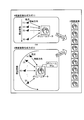
- FIG. 2A is a diagram (1) illustrating an example of a stereoscopic display monitor that performs stereoscopic display using two parallax images.
- FIG. 2B is a diagram (2) illustrating an example of a stereoscopic display monitor that performs stereoscopic display using two parallax images.
- FIG. 3 is a diagram for explaining an example of a stereoscopic display monitor that performs stereoscopic display with nine parallax images.
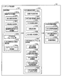
- FIG. 4 is a diagram for explaining a configuration example of the workstation according to the first embodiment.
- FIG. 5 is a diagram for explaining a configuration example of the rendering processing unit shown in FIG. FIG.
- FIG. 6 is a diagram for explaining an example of volume rendering processing according to the first embodiment.
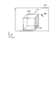
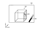
- FIG. 7 is a diagram illustrating an example of a stereoscopic image displayed on the stereoscopic display monitor.
- FIG. 8 is a diagram for explaining a configuration example of the terminal device according to the first embodiment.
- FIG. 9A is a diagram (1) for explaining the processing by the control unit in the first embodiment.
- FIG. 9B is a diagram (2) for explaining the processing by the control unit in the first embodiment.
- FIG. 10 is a diagram for explaining processing by the control unit in the first embodiment.
- FIG. 11 is a diagram for explaining processing by the control unit in the first embodiment.
- FIG. 12 is a flowchart illustrating an example of a flow of processing performed by the terminal device according to the first embodiment.
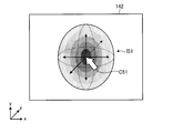
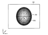
- FIG. 13 is a diagram illustrating an example of a stereoscopic image displayed by the stereoscopic display monitor according to the second embodiment.
- FIG. 14A is a diagram (1) illustrating an example of a stereoscopic image displayed by the stereoscopic display monitor according to the third embodiment.
- FIG. 14B is a diagram (2) illustrating an example of a stereoscopic image displayed by the stereoscopic display monitor according to the third embodiment.
- FIG. 15 is a diagram for explaining a configuration example of a terminal device according to the fourth embodiment.
- FIG. 16 is a diagram illustrating an example of a stereoscopic image displayed by the stereoscopic display monitor according to the fourth embodiment.
- FIG. 17A is a diagram (1) illustrating an example of a stereoscopic image displayed by the stereoscopic display monitor according to the fifth embodiment.
- FIG. 17B is a diagram (2) illustrating an example of a stereoscopic image displayed by the stereoscopic display monitor according to the fifth embodiment.
- FIG. 18 is a diagram for describing an example in which a stereoscopic image is displayed with the contrast increased only within a predetermined range.
- the “parallax image group” is an image generated by performing volume rendering processing by moving the viewpoint position by a predetermined parallax angle with respect to volume data. It is a group. That is, the “parallax image group” includes a plurality of “parallax images” having different “viewpoint positions”.
- the “parallax angle” is a predetermined position in the space represented by the volume data and an adjacent viewpoint position among the viewpoint positions set to generate the “parallax image group” (for example, the center of the space) It is an angle determined by.
- the “parallax number” is the number of “parallax images” necessary for stereoscopic viewing on the stereoscopic display monitor.
- the “9 parallax images” described below is a “parallax image group” composed of nine “parallax images”.
- the “two-parallax image” described below is a “parallax image group” composed of two “parallax images”.
- FIG. 1 is a diagram for explaining a configuration example of an image processing system according to the first embodiment.
- the image processing system 1 includes a medical image diagnostic apparatus 110, an image storage apparatus 120, a workstation 130, and a terminal apparatus 140.
- Each device illustrated in FIG. 1 is in a state where it can communicate with each other directly or indirectly by, for example, an in-hospital LAN (Local Area Network) 2 installed in a hospital.
- an in-hospital LAN Local Area Network
- PACS Picture Archiving and Communication System
- each apparatus transmits and receives medical images and the like according to the DICOM (Digital Imaging and Communications in Medicine) standard.
- DICOM Digital Imaging and Communications in Medicine
- the image processing system 1 generates a parallax image group from volume data that is three-dimensional medical image data generated by the medical image diagnostic apparatus 110, and displays the parallax image group on a stereoscopically viewable monitor.
- a stereoscopic image which is an image that can be visually recognized by the observer, is provided to an observer such as a doctor or a laboratory technician working in the hospital.
- the workstation 130 performs various image processes on the volume data to generate a parallax image group.
- the workstation 130 and the terminal device 140 have a stereoscopically visible monitor, and display a stereoscopic image to the user by displaying a parallax image group generated by the workstation 130 on the monitor.
- the image storage device 120 stores the volume data generated by the medical image diagnostic device 110 and the parallax image group generated by the workstation 130.
- the workstation 130 or the terminal device 140 acquires volume data or a parallax image group from the image storage device 120, executes arbitrary image processing on the acquired volume data or parallax image group, or selects a parallax image group. Or display on a monitor.
- each device will be described in order.
- the medical image diagnostic apparatus 110 includes an X-ray diagnostic apparatus, an X-ray CT (Computed Tomography) apparatus, an MRI (Magnetic Resonance Imaging) apparatus, an ultrasonic diagnostic apparatus, a SPECT (Single Photon Emission Computed Tomography) apparatus, and a PET (Positron Emission computed Tomography). ) Apparatus, a SPECT-CT apparatus in which a SPECT apparatus and an X-ray CT apparatus are integrated, a PET-CT apparatus in which a PET apparatus and an X-ray CT apparatus are integrated, or a group of these apparatuses. Further, the medical image diagnostic apparatus 110 according to the first embodiment can generate three-dimensional medical image data (volume data).
- the medical image diagnostic apparatus 110 generates volume data by imaging a subject.
- the medical image diagnostic apparatus 110 collects data such as projection data and MR signals by imaging the subject, and medical image data of a plurality of axial surfaces along the body axis direction of the subject from the collected data.
- volume data is generated.
- the medical image diagnostic apparatus 110 reconstructs 500 pieces of medical image data on the axial plane
- the 500 pieces of medical image data groups on the axial plane become volume data.
- the projection data of the subject imaged by the medical image diagnostic apparatus 110, the MR signal, or the like may be used as the volume data.
- the medical image diagnostic apparatus 110 transmits the generated volume data to the image storage apparatus 120.
- the medical image diagnostic apparatus 110 identifies, for example, a patient ID for identifying a patient, an examination ID for identifying an examination, and the medical image diagnostic apparatus 110 as supplementary information when transmitting volume data to the image storage apparatus 120.
- a device ID, a series ID for identifying one shot by the medical image diagnostic device 110, and the like are transmitted.
- the image storage device 120 is a database that stores medical images. Specifically, the image storage device 120 according to the first embodiment receives volume data from the medical image diagnostic device 110 and stores the received volume data in a predetermined storage unit. In the first embodiment, the workstation 130 generates a parallax image group from the volume data, and transmits the generated parallax image group to the image storage device 120. For this reason, the image storage device 120 stores the parallax image group transmitted from the workstation 130 in a predetermined storage unit. In the present embodiment, the workstation 130 illustrated in FIG. 1 and the image storage device 120 may be integrated by using the workstation 130 that can store a large-capacity image. That is, this embodiment may be a case where volume data or a parallax image group is stored in the workstation 130 itself.
- the volume data and the parallax image group stored in the image storage device 120 are stored in association with the patient ID, examination ID, device ID, series ID, and the like. For this reason, the workstation 130 and the terminal device 140 acquire necessary volume data and a parallax image group from the image storage device 120 by performing a search using a patient ID, an examination ID, a device ID, a series ID, and the like.
- the workstation 130 is an image processing apparatus that performs image processing on medical images. Specifically, the workstation 130 according to the first embodiment generates a parallax image group by performing various rendering processes on the volume data acquired from the image storage device 120.
- the workstation 130 has a monitor (also referred to as a stereoscopic display monitor or a stereoscopic image display device) capable of displaying a stereoscopic image as a display unit.
- the workstation 130 generates a parallax image group and displays the generated parallax image group on the stereoscopic display monitor.
- the operator of the workstation 130 can perform an operation for generating a parallax image group while confirming the stereoscopically viewable stereoscopic image displayed on the stereoscopic display monitor.
- the workstation 130 transmits the generated parallax image group to the image storage device 120 and the terminal device 140.
- the workstation 130 transmits, for example, a patient ID, an examination ID, a device ID, a series ID, and the like as supplementary information.
- the incidental information transmitted when transmitting the parallax image group to the image storage device 120 includes incidental information regarding the parallax image group.
- the incidental information regarding the parallax image group includes the number of parallax images (for example, “9”), the resolution of the parallax images (for example, “466 ⁇ 350 pixels”), and the volume data that is the generation source of the parallax image group.
- Information on the three-dimensional virtual space represented by (volume space information), information on the position where subject data, which is data indicating a subject such as an organ, is included in the volume data (subject location information), and the like. .
- the terminal device 140 is a device for allowing a doctor or laboratory technician working in a hospital to view a medical image.
- the terminal device 140 is a PC (Personal Computer), a tablet PC, a PDA (Personal Digital Assistant), a mobile phone, or the like operated by a doctor or laboratory technician working in a hospital.
- the terminal device 140 according to the first embodiment includes a stereoscopic display monitor as a display unit.
- the terminal device 140 acquires a parallax image group from the image storage device 120 and displays the acquired parallax image group on the stereoscopic display monitor.
- a doctor or laboratory technician who is an observer can view a medical image that can be viewed stereoscopically.
- the terminal device 140 may be any information processing terminal connected to a stereoscopic display monitor as an external device.
- a general-purpose monitor that is most popular at present displays a two-dimensional image in two dimensions, and cannot display a two-dimensional image in three dimensions. If an observer requests stereoscopic viewing on a general-purpose monitor, an apparatus that outputs an image to the general-purpose monitor needs to display two parallax images that can be viewed stereoscopically by the observer in parallel by the parallel method or the intersection method. is there.
- an apparatus that outputs an image to a general-purpose monitor for example, uses an after-color method with an eyeglass that has a red cellophane attached to the left eye portion and a blue cellophane attached to the right eye portion. It is necessary to display a stereoscopically viewable image.
- a stereoscopic display monitor there is a stereoscopic display monitor capable of stereoscopically viewing a two-parallax image (also referred to as a binocular parallax image) by using dedicated equipment such as stereoscopic glasses.
- FIGS. 2A and 2B are diagrams for explaining an example of a stereoscopic display monitor that performs stereoscopic display using two parallax images.
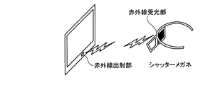
- An example shown in FIGS. 2A and 2B is a stereoscopic display monitor that performs stereoscopic display by a shutter method, and shutter glasses are used as stereoscopic glasses worn by an observer who observes the monitor.
- Such a stereoscopic display monitor emits two parallax images alternately on the monitor.
- the monitor shown in FIG. 2A alternately emits a left-eye image and a right-eye image at 120 Hz.
- the monitor is provided with an infrared emitting unit, and the infrared emitting unit controls the emission of infrared rays in accordance with the timing at which the image is switched.
- the infrared light emitted from the infrared light emitting unit is received by the infrared light receiving unit of the shutter glasses shown in FIG. 2A.
- a shutter is attached to each of the left and right frames of the shutter glasses, and the shutter glasses alternately switch the transmission state and the light shielding state of the left and right shutters according to the timing when the infrared light receiving unit receives the infrared rays.
- the switching process between the transmission state and the light shielding state in the shutter will be described.
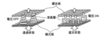
- each shutter has an incident-side polarizing plate and an output-side polarizing plate, and further has a liquid crystal layer between the incident-side polarizing plate and the output-side polarizing plate.
- the incident-side polarizing plate and the outgoing-side polarizing plate are orthogonal to each other.
- the light passing through the incident-side polarizing plate is rotated 90 degrees by the action of the liquid crystal layer, and the outgoing-side polarizing plate is To Penetrate. That is, a shutter to which no voltage is applied is in a transmissive state.
- the infrared emitting unit emits infrared rays while the image for the left eye is displayed on the monitor.
- the infrared light receiving unit applies a voltage to the right-eye shutter without applying a voltage to the left-eye shutter during a period of receiving the infrared light.
- the right-eye shutter is in a light-shielding state and the left-eye shutter is in a transmissive state, so that an image for the left eye enters the left eye of the observer.
- the infrared ray emitting unit stops emitting infrared rays while the right-eye image is displayed on the monitor.
- the infrared light receiving unit applies a voltage to the left-eye shutter without applying a voltage to the right-eye shutter during a period in which no infrared light is received. Accordingly, the left-eye shutter is in a light-shielding state and the right-eye shutter is in a transmissive state, so that an image for the right eye enters the right eye of the observer.
- the stereoscopic display monitor illustrated in FIGS. 2A and 2B displays an image that can be viewed stereoscopically by the observer by switching the image displayed on the monitor and the state of the shutter in conjunction with each other.
- a monitor adopting a polarized glasses method is also known in addition to the shutter method described above.
- a stereoscopic display monitor that allows a viewer to stereoscopically view a multi-parallax image such as a 9-parallax image with the naked eye by using a light controller such as a lenticular lens.
- a light controller such as a lenticular lens.
- Such a stereoscopic display monitor enables stereoscopic viewing based on binocular parallax, and also enables stereoscopic viewing based on motion parallax that also changes the image observed in accordance with the viewpoint movement of the observer.
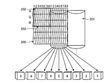
- FIG. 3 is a diagram for explaining an example of a stereoscopic display monitor that performs stereoscopic display with nine parallax images.
- a light beam controller is arranged on the front surface of a flat display surface 200 such as a liquid crystal panel.
- a vertical lenticular sheet 201 whose optical aperture extends in the vertical direction is attached to the front surface of the display surface 200 as a light beam controller.
- the projection of the vertical lenticular sheet 201 is pasted so as to be the front surface, but the projection of the vertical lenticular sheet 201 is pasted so as to face the display surface 200. There may be.
- the display surface 200 has an aspect ratio of 3: 1 and pixels in which three sub-pixels, red (R), green (G), and blue (B), are arranged in the vertical direction. 202 are arranged in a matrix.
- the stereoscopic display monitor shown in FIG. 3 converts a nine-parallax image composed of nine images into an intermediate image arranged in a predetermined format (for example, a lattice shape), and then outputs it to the display surface 200. That is, the stereoscopic display monitor shown in FIG. 3 assigns and outputs nine pixels at the same position in nine parallax images to nine columns of pixels 202.
- the nine columns of pixels 202 constitute a unit pixel group 203 that simultaneously displays nine images with different viewpoint positions.
- the nine-parallax images simultaneously output as the unit pixel group 203 on the display surface 200 are emitted as parallel light by, for example, an LED (Light Emitting Diode) backlight, and further emitted in multiple directions by the vertical lenticular sheet 201.
- an LED Light Emitting Diode
- the light incident on the right eye and the left eye of the observer changes in conjunction with the position of the observer (viewpoint position). That is, the parallax angle between the parallax image incident on the right eye and the parallax image incident on the left eye differs depending on the viewing angle of the observer.
- the observer can visually recognize the photographing object in three dimensions at each of the nine positions shown in FIG. 3, for example.
- the observer can view the image three-dimensionally in a state of facing the object to be imaged at the position “5” shown in FIG. 3, and at each position other than “5” shown in FIG. It can be visually recognized in a three-dimensional manner with the direction of the object changed.
- the stereoscopic display monitor shown in FIG. 3 is merely an example.
- the stereoscopic display monitor that displays the nine-parallax image may be a horizontal stripe liquid crystal of “RRR..., GGG..., BBB. .. ”” May be used.
- the stereoscopic display monitor shown in FIG. 3 may be a vertical lens system in which the lenticular sheet is vertical as shown in FIG. 3 or a diagonal lens system in which the lenticular sheet is oblique. There may be.
- the configuration example of the image processing system 1 according to the first embodiment has been briefly described.
- the application of the image processing system 1 described above is not limited when PACS is introduced.
- the image processing system 1 is similarly applied when an electronic medical chart system that manages an electronic medical chart to which a medical image is attached is introduced.
- the image storage device 120 is a database that stores electronic medical records.
- the image processing system 1 is similarly applied when a HIS (Hospital Information System) and a RIS (Radiology Information System) are introduced.
- HIS Hospital Information System
- RIS Radiology Information System
- the image processing system 1 is not limited to the configuration example described above. The functions and sharing of each device may be appropriately changed according to the operation mode.
- FIG. 4 is a diagram for explaining a configuration example of the workstation according to the first embodiment.
- the “parallax image group” refers to a group of stereoscopic images generated by performing volume rendering processing on volume data. Further, the “parallax image” is an individual image constituting the “parallax image group”. That is, the “parallax image group” includes a plurality of “parallax images” having different viewpoint positions.
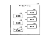
- the workstation 130 is a high-performance computer suitable for image processing and the like, and as illustrated in FIG. 4, an input unit 131, a display unit 132, a communication unit 133, and a storage unit 134. And a control unit 135 and a rendering processing unit 136.
- the workstation 130 is a high-performance computer suitable for image processing or the like.
- the present invention is not limited to this, and may be any information processing apparatus. For example, any personal computer may be used.
- the input unit 131 is a mouse, a keyboard, a trackball, or the like, and receives input of various operations on the workstation 130 from the operator. Specifically, the input unit 131 according to the first embodiment receives input of information for acquiring volume data to be subjected to rendering processing from the image storage device 120. For example, the input unit 131 receives input of a patient ID, an examination ID, a device ID, a series ID, and the like. Further, the input unit 131 according to the first embodiment receives an input of a condition regarding rendering processing (hereinafter, rendering condition).
- rendering condition a condition regarding rendering processing
- the display unit 132 is a liquid crystal panel or the like as a stereoscopic display monitor, and displays various types of information. Specifically, the display unit 132 according to the first embodiment displays a GUI (Graphical User Interface) for receiving various operations from the operator, a parallax image group, and the like.
- the communication unit 133 is a NIC (Network Interface Card) or the like, and communicates with other devices.
- the storage unit 134 is a hard disk, a semiconductor memory element, or the like, and stores various information. Specifically, the storage unit 134 according to the first embodiment stores volume data acquired from the image storage device 120 via the communication unit 133. In addition, the storage unit 134 according to the first embodiment stores volume data during rendering processing, a group of parallax images generated by the rendering processing, and the like.
- the control unit 135 is an electronic circuit such as a CPU (Central Processing Unit), MPU (Micro Processing Unit) or GPU (Graphics Processing Unit), or an integrated circuit such as an ASIC (Application Specific Integrated Circuit) or FPGA (Field Programmable Gate Array). Yes, the entire control of the workstation 130 is performed.
- CPU Central Processing Unit
- MPU Micro Processing Unit
- GPU Graphics Processing Unit
- ASIC Application Specific Integrated Circuit
- FPGA Field Programmable Gate Array
- control unit 135 controls the display of the GUI and the display of the parallax image group on the display unit 132.
- the control unit 135 controls transmission / reception of volume data and a parallax image group performed with the image storage device 120 via the communication unit 133.
- the control unit 135 controls the rendering process performed by the rendering processing unit 136.
- the control unit 135 controls reading of volume data from the storage unit 134 and storage of the parallax image group in the storage unit 134.
- the rendering processing unit 136 performs various rendering processes on the volume data acquired from the image storage device 120 under the control of the control unit 135, and generates a parallax image group. Specifically, the rendering processing unit 136 according to the first embodiment reads volume data from the storage unit 134 and first performs preprocessing on the volume data. Next, the rendering processing unit 136 performs a volume rendering process on the pre-processed volume data to generate a parallax image group. Subsequently, the rendering processing unit 136 generates a two-dimensional image in which various kinds of information (scale, patient name, examination item, etc.) are drawn, and superimposes it on each of the parallax image groups, thereby outputting 2 for output. Generate a dimensional image.
- rendering processing refers to the entire image processing performed on volume data.
- Volume rendering processing refers to a two-dimensional image reflecting three-dimensional information in the rendering processing. It is a process to generate.
- a parallax image corresponds to the medical image generated by the rendering process.
- FIG. 5 is a diagram for explaining a configuration example of the rendering processing unit shown in FIG.
- the rendering processing unit 136 includes a preprocessing unit 1361, a 3D image processing unit 1362, and a 2D image processing unit 1363.
- the preprocessing unit 1361 performs preprocessing on the volume data
- the 3D image processing unit 1362 generates a parallax image group from the preprocessed volume data
- the 2D image processing unit 1363 stores various information on the parallax image group.
- a two-dimensional image for output on which is superimposed is generated.
- each part is demonstrated in order.
- the preprocessing unit 1361 is a processing unit that performs various types of preprocessing when rendering processing is performed on volume data, and includes an image correction processing unit 1361a, a three-dimensional object fusion unit 1361e, and a three-dimensional object display area setting. Part 1361f.
- the image correction processing unit 1361a is a processing unit that performs image correction processing when processing two types of volume data as one volume data, and as illustrated in FIG. 5, a distortion correction processing unit 1361b, a body motion correction processing unit, 1361c and an inter-image registration processing unit 1361d.
- the image correction processing unit 1361a performs image correction processing when processing volume data of a PET image generated by a PET-CT apparatus and volume data of an X-ray CT image as one volume data.
- the image correction processing unit 1361a performs image correction processing when processing the volume data of the T1-weighted image and the volume data of the T2-weighted image generated by the MRI apparatus as one volume data.
- the distortion correction processing unit 1361b corrects the data distortion caused by the collection conditions at the time of data collection by the medical image diagnostic apparatus 110 in each volume data.
- the body motion correction processing unit 1361c corrects the movement caused by the body motion of the subject at the time of collecting the data used for generating the individual volume data.
- the inter-image registration processing unit 1361d performs registration (Registration) using, for example, a cross-correlation method between the two volume data subjected to the correction processing by the distortion correction processing unit 1361b and the body motion correction processing unit 1361c. )I do.
- the three-dimensional object fusion unit 1361e fuses a plurality of volume data that have been aligned by the inter-image alignment processing unit 1361d. Note that the processing of the image correction processing unit 1361a and the three-dimensional object fusion unit 1361e is omitted when rendering processing is performed on single volume data.
- the three-dimensional object display area setting unit 1361f is a processing unit that sets a display area corresponding to a display target organ designated by the operator, and includes a segmentation processing unit 1361g.
- the segmentation processing unit 1361g is a processing unit that extracts organs such as the heart, lungs, and blood vessels designated by the operator by, for example, a region expansion method based on pixel values (voxel values) of volume data.
- segmentation processing unit 1361 g does not perform the segmentation processing when the display target organ is not designated by the operator.
- the segmentation processing unit 1361g extracts a plurality of corresponding organs when a plurality of display target organs are designated by the operator. Further, the processing of the segmentation processing unit 1361g may be executed again in response to an operator fine adjustment request referring to the rendered image.
- the 3D image processing unit 1362 performs a volume rendering process on the pre-processed volume data processed by the pre-processing unit 1361.
- a 3D image processing unit 1362 includes a projection method setting unit 1362a, a 3D geometric transformation processing unit 1362b, a 3D object appearance processing unit 1362f, and a 3D virtual space rendering unit 1362k.
- Projection method setting unit 1362a determines a projection method for generating a parallax image group. For example, the projection method setting unit 1362a determines whether to execute the volume rendering process by the parallel projection method or the perspective projection method.
- the three-dimensional geometric transformation processing unit 1362b is a processing unit that determines information for transforming volume data on which volume rendering processing is performed into a three-dimensional geometrical structure.
- the three-dimensional geometric transformation processing unit 1362b includes a parallel movement processing unit 1362c, a rotation processing unit 1362d, and an enlargement unit.
- a reduction processing unit 1362e is included.
- the parallel movement processing unit 1362c is a processing unit that determines the amount of movement to translate the volume data when the viewpoint position when performing the volume rendering process is translated, and the rotation processing unit 1362d performs the volume rendering process. This is a processing unit that determines the amount of movement to rotate the volume data when the viewpoint position at the time of rotation is rotated.
- the enlargement / reduction processing unit 1362e is a processing unit that determines the enlargement rate or reduction rate of the volume data when enlargement or reduction of the parallax image group is requested.
- the 3D object appearance processing unit 1362f includes a 3D object color processing unit 1362g, a 3D object opacity processing unit 1362h, a 3D object material processing unit 1362i, and a 3D virtual space light source processing unit 1362j.
- the three-dimensional object appearance processing unit 1362f performs a process of determining the display state of the displayed parallax image group in response to an operator's request, for example.
- the three-dimensional object color processing unit 1362g is a processing unit that determines a color to be colored for each region segmented by the volume data.
- the three-dimensional object opacity processing unit 1362h is a processing unit that determines the opacity (Opacity) of each voxel constituting each region segmented by volume data. It should be noted that the area behind the area having the opacity of “100%” in the volume data is not drawn in the parallax image group. In addition, an area in which the opacity is “0%” in the volume data is not drawn in the parallax image group.
- the three-dimensional object material processing unit 1362i is a processing unit that determines the material of each region segmented by volume data and adjusts the texture when this region is rendered.
- the three-dimensional virtual space light source processing unit 1362j is a processing unit that determines the position of the virtual light source installed in the three-dimensional virtual space and the type of the virtual light source when performing volume rendering processing on the volume data. Examples of the virtual light source include a light source that emits parallel light rays from infinity and a light source that emits radial light rays from the viewpoint.
- the 3D virtual space rendering unit 1362k performs volume rendering processing on the volume data to generate a parallax image group.
- the three-dimensional virtual space rendering unit 1362k performs various types of information determined by the projection method setting unit 1362a, the three-dimensional geometric transformation processing unit 1362b, and the three-dimensional object appearance processing unit 1362f as necessary when performing the volume rendering process. Is used.
- the volume rendering process by the three-dimensional virtual space rendering unit 1362k is performed according to the rendering conditions.
- the rendering condition is “parallel projection method” or “perspective projection method”.
- the rendering condition is “reference viewpoint position and parallax angle”.
- the rendering conditions are “translation of viewpoint position”, “rotational movement of viewpoint position”, “enlargement of parallax image group”, and “reduction of parallax image group”.
- the rendering conditions are “color to be colored”, “transparency”, “texture”, “position of virtual light source”, and “type of virtual light source”.
- Such a rendering condition may be accepted from the operator via the input unit 131 or may be initially set.
- the three-dimensional virtual space rendering unit 1362k receives a rendering condition from the control unit 135, and performs volume rendering processing on the volume data according to the rendering condition.
- the projection method setting unit 1362a, the three-dimensional geometric transformation processing unit 1362b, and the three-dimensional object appearance processing unit 1362f determine various pieces of necessary information according to the rendering conditions, so the three-dimensional virtual space rendering unit 1362k. Generates a parallax image group using the determined various pieces of information.
- FIG. 6 is a diagram for explaining an example of the volume rendering process according to the first embodiment.
- the three-dimensional virtual space rendering unit 1362k accepts the parallel projection method as a rendering condition, and further, the reference viewpoint position (5) and the parallax. Assume that the angle “1 degree” is received. In such a case, the three-dimensional virtual space rendering unit 1362k translates the position of the viewpoint from (1) to (9) so that the parallax angle is every “1 degree”, and performs the parallax angle (line of sight) by the parallel projection method.
- Nine parallax images with different degrees between directions are generated.
- the three-dimensional virtual space rendering unit 1362k sets a light source that emits parallel light rays from infinity along the line-of-sight direction.
- the three-dimensional virtual space rendering unit 1362k accepts a perspective projection method as a rendering condition, and further, the reference viewpoint position (5) and the parallax Assume that the angle “1 degree” is received. In such a case, the three-dimensional virtual space rendering unit 1362k rotates and moves the viewpoint position from (1) to (9) so that the parallax angle is “1 degree” around the center (center of gravity) of the volume data. Thus, nine parallax images having different parallax angles by 1 degree are generated by the perspective projection method.
- the three-dimensional virtual space rendering unit 1362k sets a point light source or a surface light source that radiates light three-dimensionally radially around the viewing direction at each viewpoint.
- the viewpoints (1) to (9) may be moved in parallel depending on rendering conditions.
- the three-dimensional virtual space rendering unit 1362k radiates light two-dimensionally radially around the line-of-sight direction with respect to the vertical direction of the displayed volume rendered image, and the horizontal direction of the displayed volume rendered image.
- volume rendering processing using both the parallel projection method and the perspective projection method may be performed by setting a light source that irradiates parallel light rays from infinity along the line-of-sight direction.
- the nine parallax images generated in this way are a group of parallax images.
- the nine parallax images are converted into intermediate images arranged in a predetermined format (for example, a lattice shape) by the control unit 135, for example, and are output to the display unit 132 as a stereoscopic display monitor.
- the operator of the workstation 130 can perform an operation for generating a parallax image group while confirming a stereoscopically viewable medical image displayed on the stereoscopic display monitor.
- the rendering unit 1362k generates a parallax image group while reflecting each rendering condition.
- the 3D virtual space rendering unit 1362k has a function of reconstructing an MPR image from volume data by performing a cross-section reconstruction method (MPR: Multi Planer Reconstruction) in addition to volume rendering.
- MPR Multi Planer Reconstruction
- the three-dimensional virtual space rendering unit 1362k also has a function of performing “Curved MPR” and a function of performing “Intensity Projection”.
- the parallax image group generated from the volume data by the three-dimensional image processing unit 1362 is an underlay.
- an overlay (Overlay) on which various types of information (scale, patient name, examination item, etc.) are drawn is superimposed on the underlay, thereby obtaining a two-dimensional image for output.
- the two-dimensional image processing unit 1363 is a processing unit that generates an output two-dimensional image by performing image processing on the overlay and the underlay. As illustrated in FIG. 5, the two-dimensional object drawing unit 1363a, A two-dimensional geometric transformation processing unit 1363b and a luminance adjustment unit 1363c are included.
- the two-dimensional image processing unit 1363 superimposes one overlay on each of nine parallax images (underlays) in order to reduce the load required to generate a two-dimensional image for output.
- nine output two-dimensional images are generated.
- an underlay with an overlay superimposed may be simply referred to as a “parallax image”.
- the two-dimensional object drawing unit 1363a is a processing unit that draws various information drawn on the overlay, and the two-dimensional geometric transformation processing unit 1363b performs parallel movement processing or rotational movement processing on the position of the various information drawn on the overlay. Or a processing unit that performs an enlargement process or a reduction process of various types of information drawn on the overlay.
- the luminance adjustment unit 1363c is a processing unit that performs luminance conversion processing. For example, an image such as gradation of an output destination stereoscopic display monitor, window width (WW: Window Width), window level (WL: Window Level), or the like. This is a processing unit that adjusts the brightness of the overlay and the underlay according to the processing parameters.
- WW Window Width
- WL Window Level
- the control unit 135 temporarily stores the output two-dimensional image generated in this manner in the storage unit 134 and then transmits the two-dimensional image to the image storage device 120 via the communication unit 133. Then, for example, the terminal device 140 acquires the two-dimensional image for output from the image storage device 120, converts it into an intermediate image arranged in a predetermined format (for example, a lattice shape), and displays it on the stereoscopic display monitor. For example, the control unit 135 temporarily stores the output two-dimensional image in the storage unit 134, and then transmits the output two-dimensional image to the image storage device 120 and the terminal device 140 via the communication unit 133.
- a predetermined format for example, a lattice shape
- the terminal device 140 converts the output two-dimensional image received from the workstation 130 into an intermediate image arranged in a predetermined format (for example, a lattice shape) and displays the converted image on the stereoscopic display monitor. Accordingly, a doctor or a laboratory technician who uses the terminal device 140 can browse a stereoscopically viewable medical image in a state where various information (scale, patient name, examination item, etc.) is drawn.
- a predetermined format for example, a lattice shape
- the terminal device 140 displays a stereoscopic image that is a stereoscopically visible image for the observer using a plurality of parallax images on the stereoscopic display monitor.
- the terminal device 140 also displays a cursor that can be operated by a pointing device such as a mouse together with the stereoscopic image.
- a cursor can be moved three-dimensionally in a three-dimensional space in which a stereoscopic image is displayed (hereinafter sometimes referred to as “stereoscopic image space”).
- stereoscopic image space For example, an observer sets a region of interest (ROI: Region Of Interest) by moving a cursor and specifying a predetermined part of a stereoscopic image.
- ROI Region Of Interest
- the stereoscopic image space is generally formed as a space before and after the display surface of the stereoscopic display monitor 142.
- FIG. 7 is a diagram illustrating an example of a stereoscopic image displayed on the stereoscopic display monitor.
- the cursor C ⁇ b> 10 is displayed together with the stereoscopic image I ⁇ b> 10 on the stereoscopic display monitor 142 included in the terminal device 140.
- the three-dimensional image I10 is illustrated three-dimensionally on a two-dimensional surface. However, the three-dimensional image I10 is displayed in a three-dimensional space that is a three-dimensional space so as to be stereoscopically viewable. ing.
- the position of the cursor C10 in the depth direction (z direction in FIG. 7) in the stereoscopic image space is Difficult to grasp.
- the cursor C10 shown in FIG. 7 is displayed at a position between the front surface I10a and the rear surface I10b of the stereoscopic image I10, and is displayed on the front side (direction closer to the observer) than the front surface I10a. It can also be seen that it is displayed behind the rear surface I10b (in the direction away from the observer). For this reason, it is difficult for the observer to grasp the position of the cursor C10.
- the terminal device 140 According to the first embodiment generates an image of a predetermined graphic representing the position of the cursor in the depth direction in the stereoscopic image space, and for the plurality of parallax images generated by the rendering processing unit 136, The graphic image is superimposed and displayed on the stereoscopic display monitor 142. Thereby, the terminal device 140 in 1st Embodiment enables an observer to grasp
- FIG. 8 is a diagram for describing a configuration example of the terminal device 140 according to the first embodiment.
- the terminal device 140 according to the first embodiment includes an input unit 141, a stereoscopic display monitor 142, a communication unit 143, a storage unit 144, and a control unit 145.
- the input unit 141 is a pointing device such as a mouse or a trackball, or an information input device such as a keyboard, and receives input of various operations on the terminal device 140 from an operator.
- the input unit 141 accepts input of a patient ID, an examination ID, a device ID, a series ID, and the like for designating volume data for which the operator desires stereoscopic vision as a stereoscopic vision request.
- the input unit 141 receives an operation of moving the cursor displayed on the stereoscopic display monitor 142 via the mouse.
- the stereoscopic display monitor 142 is a liquid crystal panel or the like as a stereoscopic display monitor, and displays various types of information. Specifically, the stereoscopic display monitor 142 according to the first embodiment displays a GUI (Graphical User Interface) for receiving various operations from the operator, a parallax image group, and the like.
- the stereoscopic display monitor 142 may be a stereoscopic display monitor (hereinafter referred to as a 2-parallax monitor) described with reference to FIGS. 2A and 2B, or a stereoscopic display monitor (hereinafter referred to as a 9-parallax monitor) described with reference to FIG. Described).
- a stereoscopic display monitor 142 is a nine-parallax monitor will be described.
- the communication unit 143 is a NIC (Network Interface Card) or the like, and communicates with other devices. Specifically, the communication unit 143 according to the first embodiment transmits the stereoscopic request received by the input unit 141 to the image storage device 120. In addition, the communication unit 143 according to the first embodiment receives a parallax image group transmitted by the image storage device 120 in response to a stereoscopic request.
- NIC Network Interface Card
- the storage unit 144 is a hard disk, a semiconductor memory element, or the like, and stores various types of information. Specifically, the storage unit 144 according to the first embodiment stores a parallax image group acquired from the image storage device 120 via the communication unit 143. The storage unit 144 also stores incidental information (number of parallaxes, resolution, volume space information, subject position information, and the like) of the parallax image group acquired from the image storage device 120 via the communication unit 143.
- the control unit 145 is an electronic circuit such as a CPU, MPU, or GPU, or an integrated circuit such as an ASIC or FPGA, and performs overall control of the terminal device 140.
- the control unit 145 controls transmission / reception of a stereoscopic request and a parallax image group performed with the image storage device 120 via the communication unit 143.
- the control unit 145 controls storage of the parallax image group in the storage unit 144 and reading of the parallax image group from the storage unit 144.
- the control unit 145 superimposes a cursor image (overlay) that can be operated by the input unit 141 such as a pointing device on the parallax image group (underlay) received from the image storage device 120.
- control unit 145 includes an operation control unit 1451, a graphic image generation unit 1452, and a display control unit 1453, and the cursor is pointed by the processing performed by these processing units. This makes it easy to grasp the position in the depth direction.
- the operation control unit 1451 performs various processes according to various operations received by the input unit 141. For example, the operation control unit 1451 transmits the stereoscopic request to the workstation 130 via the communication unit 143 when the input of the stereoscopic request is received by the input unit 141.
- the operation control unit 1451 controls the position of the cursor displayed on the stereoscopic display monitor 142 when the input unit 141 such as a pointing device is operated.
- the operation control unit 1451 in the first embodiment manages the three-dimensional position of the cursor in the three-dimensional space represented by the same coordinate system as the volume data that is the generation source of the parallax image group.
- the three-dimensional space in which the three-dimensional position of the cursor is managed by the operation control unit 1451 may be referred to as “cursor virtual space”.
- the terminal device 140 uses the volume space information related to the three-dimensional space represented by the volume data that is the generation source of the parallax image group as supplementary information related to the parallax image group from the image storage device 120. To get.
- the operation control unit 1451 manages the three-dimensional position of the cursor in the cursor virtual space represented by the same coordinate system as the coordinate system of the three-dimensional space indicated by the volume space information.
- the operation control unit 1451 moves the cursor in the cursor virtual space when an operation for moving the cursor is performed via the input unit 141.
- the display control unit 1453 generates three-dimensional image data by arranging a cursor image in the cursor virtual space, and generates an overlay that is a cursor image from the generated three-dimensional image data. Then, the operation control unit 1451 controls display on the stereoscopic display monitor 142 after superimposing the overlay on the parallax image group.
- the graphic image generation unit 1452 generates a graphic image that is an image of a predetermined graphic that represents the position in the depth direction of the cursor that can be operated by the input unit 141 in the stereoscopic image space in which the stereoscopic image is displayed on the stereoscopic display monitor 142.
- the graphic image generation unit 1452 according to the first embodiment generates a graphic image including a cursor image and a graphic image representing the position of the cursor in the depth direction.
- the “graphic image” is an overlay to be superimposed on the parallax image group (underlay) acquired from the image storage device 120.
- the processing by the graphic image generation unit 1452 will be specifically described.
- the graphic image generation unit 1452 first acquires the position of the cursor in the cursor virtual space from the operation control unit 1451. Then, the graphic image generation unit 1452 arranges the cursor image data at the acquired position in the cursor virtual space, and arranges graphic image data representing the position of the cursor at a predetermined position in the cursor virtual space. “3D graphic data”, which is 3D image data, is generated. Then, the graphic image generation unit 1452 generates a plurality of graphic images by performing volume rendering processing on the three-dimensional graphic data from a plurality of viewpoint positions. At this time, the graphic image generation unit 1452 performs the volume rendering process from the same viewpoint position as when generating the parallax image group.
- the rendering processing unit 136 rotates the volume data with the viewpoint position and the line-of-sight direction fixed, or changes the viewpoint position and the line-of-sight direction with the volume data fixed, thereby changing the position relative to the volume data.
- a plurality of parallax images are generated by performing rendering processing from a plurality of viewpoint positions with different values. Similar to the plurality of viewpoint positions when the rendering processing unit 136 generates the parallax image group, the graphic image generation unit 1452 applies the three-dimensional graphic data to the three-dimensional graphic data from a plurality of viewpoint positions different from the three-dimensional graphic data. Perform volume rendering processing.
- the graphic image generation unit 1452 displays an image such as a straight line or a two-dimensional plane as a graphic representing the position of the cursor on a plane in the cursor virtual space where the position in the depth direction is the same as that of the cursor.
- Three-dimensional graphic data is generated by arranging the data.
- the graphic image generation unit 1452 is based on the subject position information acquired from the image storage device 120, and the subject in the three-dimensional virtual space in which the volume data that is the generation source of the parallax image group is arranged. An area where data exists is specified, and an area of the cursor virtual space corresponding to the specified area is specified. That is, the graphic image generation unit 1452 specifies the region in the cursor virtual space corresponding to the region where the subject data exists by using the subject position information, although the subject data does not exist in the cursor virtual space. .
- the graphic image generation unit 1452 in the first embodiment shows the area where the subject data exists on the plane in the cursor virtual space where the position in the depth direction is the same as that of the cursor, and the position indicated by the cursor.
- Three-dimensional graphic data is generated by arranging straight line image data in the cursor virtual space.
- the graphic image generation unit 1452 includes a part or all of the region where the subject data exists on the plane in the cursor virtual space where the position in the depth direction is the same as that of the cursor, and the position indicated by the cursor.
- Three-dimensional graphic data is generated by arranging two-dimensional plane image data in the cursor virtual space.
- the graphic image generation unit 1452 according to the first embodiment generates a plurality of graphic images by performing volume rendering processing on the three-dimensional graphic data including the straight line and the two-dimensional plane image data as described above. .
- the display control unit 1453 superimposes the graphic image generated by the graphic image generation unit 1452 on the parallax image group acquired from the image storage device 120 and causes the stereoscopic display monitor 142 to display the superimposed image. Specifically, for each of the parallax images generated by the rendering processing unit 136, the display control unit 1453 selects a graphic image having the same viewpoint position from among a plurality of graphic images generated by the graphic image generation unit 1452. A superimposed image is generated, and the generated superimposed image is displayed on the stereoscopic display monitor 142.
- FIGS. 9A to 11 are diagrams for explaining processing by the control unit 145 in the first embodiment.
- a straight line is displayed as a graphic representing the position of the cursor will be described with reference to FIGS. 9A, 9B, and 10.
- the rendering processing unit 136 of the workstation 130 generates nine parallax images U11 to U19 by performing rendering processing on the volume data VD10 from a plurality of viewpoint positions.
- the volume data VD10 includes subject data VD11 that is data indicating the organ of the subject.
- the subject data VD11 corresponds to the stereoscopic image I10 illustrated in FIG.
- data other than the subject data VD11 indicates other than the subject such as air.
- the workstation 130 stores the nine parallax images U11 to U19 thus generated in the image storage device 120, and the terminal device 140 acquires the parallax images U11 to U19 from the image storage device 120.
- the operation control unit 1451 of the terminal device 140 manages the three-dimensional position of the cursor in the cursor virtual space SP10 represented by the same coordinate system as the volume data VD10, as in the example illustrated in FIG. 9B.
- the graphic image generation unit 1452 acquires the position of the cursor in the cursor virtual space from the operation control unit 1451, arranges the cursor image data D11 at the acquired position, and sets the cursor and the depth direction.
- Linear image data D12 is arranged on a plane SP11 in the cursor virtual space SP10 having the same position.
- the graphic image generation unit 1452 identifies the area of the subject data existing in the three-dimensional virtual space of the volume data based on the subject position information acquired from the image storage device 120, and corresponds to the identified area. An area of the cursor virtual space SP10 is specified. Then, as illustrated in FIG. 9B, the graphic image generation unit 1452 arranges, in the cursor virtual space, linear image data D12 that connects the area A13 where the subject data exists on the plane SP11 and the position indicated by the cursor. To generate three-dimensional graphic data.
- the graphic image generation unit 1452 may arrange any shape line on the plane SP11 as long as the line connects the cursor and the subject. For example, the graphic image generation unit 1452 may arrange, on the plane SP11, the position indicated by the cursor and the straight line image data D12 passing through the center and the center of gravity of the area A13.
- the graphic image generation unit 1452 generates graphic images O11 to O19 by performing volume rendering processing on the three-dimensional graphic data in which the image data D11 and the image data D12 are arranged. At this time, the graphic image generation unit 1452 performs the rendering process under the same conditions as the rendering conditions (the viewpoint position, the parallax angle, the parallax number, and the like) when the rendering process is performed on the volume data VD10 by the rendering processing unit 136. Do. In the example shown in FIGS. 9A and 9B, both images in which N matches among the parallax images U “N (N is 11 to 19)” and the graphic image O “N (N is 11 to 19)”. Are generated by performing a rendering process under the same rendering conditions. For example, it is assumed that the parallax image U11 and the graphic image O11 are generated by performing a rendering process under the same rendering condition.
- the display control unit 1453 then displays the graphic image in which the viewpoint position is the same among the graphic images O11 to O19 generated by the graphic image generation unit 1452 for each of the parallax images U11 to U19 generated by the rendering processing unit 136. Are superimposed on each other, and the generated superimposed image is displayed on the stereoscopic display monitor 142. 9A and 9B, the display control unit 1453 generates a superimposed image in which the graphic image O11 is superimposed on the parallax image U11, and similarly, the parallax images U12 to U19. A superimposed image is generated by superimposing any of the graphic images O12 to O19 having the same viewpoint position on each of them.
- the display control unit 1453 displays the generated nine superimposed images on the stereoscopic display monitor 142.
- nine superimposed images are displayed on the stereoscopic display monitor 142, and as a result, a stereoscopic image that can be stereoscopically viewed by the observer is displayed.
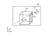
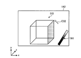
- the stereoscopic display monitor 142 displays a stereoscopic image I10 showing the subject and a cursor C10. Furthermore, the stereoscopic display monitor 142 displays a straight line image I11 that connects the position indicated by the cursor C10 and the stereoscopic image I10.
- the straight line image I11 corresponds to the straight line image data D11 shown in FIG. 9B, and is displayed on a plane having the same position in the depth direction as the cursor C10 in the stereoscopic image space. Since the straight line image I11 connects the position pointed to by the cursor C10 and the stereoscopic image I10, the observer observing the stereoscopic display monitor 142 illustrated in FIG.
- the 10 can grasp the position of the cursor C10 in the depth direction. . Specifically, the observer can grasp the position of the cursor C10 in the depth direction with reference to the stereoscopic image I10 by observing the intersection P11 and the intersection P12 between the cursor C10 and the stereoscopic image I10.
- the terminal device 140 displays the linear image I11 connecting the cursor C10 and the stereoscopic image I10 indicating the subject.
- the terminal device 140 displays the stereoscopic image I10 indicating the cursor C10 and the subject. You may display lines, such as a line segment and a half line.
- the graphic image generation unit 1452 generates three-dimensional graphic data by arranging linear image data D12 on the plane SP11.
- the graphic image generation unit 1452 may generate three-dimensional graphic data by arranging two-dimensional flat image data of a predetermined size on the plane SP11.
- the graphic image generation unit 1452 generates three-dimensional graphic data by arranging two-dimensional plane image data on the plane SP11 in the cursor virtual space SP10 in the example shown in FIG. 9B.
- the graphic image generation unit 1452 arranges, in the cursor virtual space, two-dimensional plane image data including part or all of the area A13 where the subject data exists on the plane SP11 and the position indicated by the cursor. Three-dimensional graphic data is generated.
- the display control unit 1453 generates a graphic generated by the graphic image generation unit 1452 for each of the parallax images U11 to U19 generated by the rendering processing unit 136.
- Nine superimposed images are generated by superimposing graphic images having the same viewpoint position among the images, and the generated nine superimposed images are displayed on the stereoscopic display monitor 142.
- a stereoscopic image is displayed on the stereoscopic display monitor 142 using the nine superimposed images.
- the stereoscopic display monitor 142 displays a stereoscopic image I10 showing the subject and a cursor C10. Furthermore, the stereoscopic display monitor 142 displays a planar image I21 including the position indicated by the cursor C10 and the stereoscopic image I10. As described above, the planar image I21 is displayed on a plane having the same position in the depth direction as the cursor C10 in the stereoscopic image space. Since the planar image I21 includes the position pointed to by the cursor C10 and the stereoscopic image I10, the observer observing the stereoscopic display monitor 142 illustrated in FIG. 11 can grasp the position of the cursor C10 in the depth direction. . Specifically, the observer can grasp the position of the cursor C10 in the depth direction with reference to the stereoscopic image I10 by observing the intersection line P20 between the cursor C10 and the stereoscopic image I10.
- the graphic image generation unit 1452 and the display control unit 1453 described above perform a process of displaying a graphic image (a linear image I11 or a planar image I21) indicating the position of the cursor in the depth direction each time the cursor moves. That is, in the example shown in FIGS. 10 and 11, the straight line image I11 and the planar image I21 also move with the movement of the cursor.
- FIG. 12 is a flowchart illustrating an example of a flow of processing performed by the terminal device 140 according to the first embodiment.
- the control unit 145 of the terminal device 140 determines whether or not a stereoscopic vision request is input from the observer via the input unit 141 (step S101).
- a stereoscopic vision request is not input (No at Step S101)
- the terminal device 140 stands by until a stereoscopic vision request is input.
- the control unit 145 acquires a parallax image group from the image storage device 120 by transmitting the stereoscopic vision request to the image storage device 120 ( Step S102).
- the graphic image generation unit 1452 of the control unit 145 generates three-dimensional graphic data by arranging the image data of the cursor and image data such as a straight line or a two-dimensional plane representing the position of the cursor in the cursor virtual space. (Step S103). Then, the graphic image generation unit 1452 generates a plurality of graphic images by performing volume rendering processing on the three-dimensional graphic data (step S104).
- the display control unit 1453 of the control unit 145 selects a graphic image whose viewpoint position matches among the plurality of graphic images generated by the graphic image generation unit 1452 with respect to the parallax image group acquired from the image storage device 120. By superimposing, a plurality of superimposed images are generated (step S105). Then, the display control unit 1453 displays the generated superimposed image on the stereoscopic display monitor 142 (step S106).
- the observer can grasp the position of the cursor displayed together with the stereoscopic image. it can.
- the graphic image generation unit 1452 connects the area A13 where the subject data exists and the position indicated by the cursor.
- An example is shown in which three-dimensional graphic data is generated by arranging straight line image data in the cursor virtual space, and the display control unit 1453 displays a straight line image connecting the cursor and the subject.
- the graphic image generation unit 1452 arranges, in the cursor virtual space, linear image data that connects the position pointed to by the cursor and the center or the center of gravity of the cursor virtual space without specifying the region A13 where the subject data exists. Also good.
- the subject data VD11 is generally often located at the center of the volume data VD10. Therefore, in the example shown in FIG. 9B, a straight line connecting the position pointed to by the cursor and the center or center of gravity of the cursor virtual space generally passes through the area A13 corresponding to the position of the subject data VD11. For this reason, the graphic image generation unit 1452 may arrange straight line image data connecting the position indicated by the cursor and the center or the center of gravity of the plane SP11 in the cursor virtual space. In the case of processing in this way, the graphic image generation unit 1452 does not need to perform processing for specifying the region A13 in which the subject data exists, and therefore, the load on the processing for generating the graphic image can be reduced. .
- the graphic image generation unit 1452 converts the two-dimensional plane image data including the position indicated by the cursor and the center or the center of gravity of the plane SP11 to the cursor virtual space. It is also possible to generate three-dimensional graphic data by arranging them at the positions. Even in such a case, the graphic image generation unit 1452 does not need to perform the process of specifying the region A13 in which the subject data exists, so that the load on the process of generating the graphic image can be reduced.
- the terminal device 140 displays the straight line image I11 and the planar image I21 illustrated in FIGS. 9A, 9B, and 10. May be.
- the terminal device 140 may receive information regarding the shape of the straight line image I11 illustrated in FIG. 10 and the shape of the planar image I21 illustrated in FIG. For example, the terminal device 140 may accept an angle formed by the straight line image I11 and the horizontal direction (x-axis direction) or the opacity (Opacity) of the straight line image I11 via the input unit 141. Then, a request for displaying the straight line image I11 as a dotted line or a curve instead of a straight line may be received.
- the terminal device 140 may accept the size of the planar image I21, may accept the opacity of the planar image I21, or the planar image I21 may be a polygon other than a rectangle, a circle, or an ellipse.
- a request for display in a form or the like may be accepted.
- the graphic image generation unit 1452 determines the shape of the straight line image I11 or the planar image I21 based on the information regarding the shape received via the input unit 141.
- the terminal device 140 may display not only the planar image I21 parallel to the xy plane but also a planar image orthogonal to the planar image I21 as in the example illustrated in FIG. . That is, the terminal device 140 may display a plane image parallel to the xz plane or a plane image parallel to the yz plane in addition to the plane image parallel to the xy plane.
- the operation control unit 1451 restricts the movable range of the cursor to a position where the linear image I11 is displayed when a predetermined operation is performed via the input unit 141. May be.
- the operation control unit 1451 displays the straight line image I11 when a predetermined operation is performed in a state where the various images illustrated in FIG. 10 are displayed on the stereoscopic display monitor 142.
- the display position may be fixed and the movable range of the cursor C10 may be limited only to the straight line image I11.
- the operation control unit 1451 may fix the display position of the straight line image I11 and restrict the movable range of the cursor C10 only on the straight line image I11 in the stereoscopic image I10.
- the operation control unit 1451 fixes the display position of the linear image I11 and moves the cursor C10 to the intersection P11 or the intersection P12 between the stereoscopic image I10 and the linear image I11. Also good.
- the operation control unit 1451 performs the planar image I21 when a predetermined operation is performed in a state where various images illustrated in FIG. 11 are displayed on the stereoscopic display monitor 142. May be fixed, and the movable range of the cursor C10 may be limited only to the planar image I21. Further, the operation control unit 1451 may fix the display position of the planar image I21 and restrict the movable range of the cursor C10 to only the planar image I21 in the stereoscopic image I10. In addition, when a predetermined operation is performed, the operation control unit 1451 fixes the display position of the planar image I21 and also moves the cursor C10 to the intersection line P20 between the stereoscopic image I10 and the planar image I21. Good.
- the operation control unit 1451 when the operation control unit 1451 is displaying a plane image orthogonal to the plane image I21 (a plane image parallel to the xz plane or a plane image parallel to the yz plane), the plane image parallel to the xz plane is displayed.
- the display position of the plane image parallel to the yz plane is also fixed, and the movable range of the cursor C10 is only on the plane image I21, the plane image parallel to the xz plane, or the plane image parallel to the yz plane. May be restricted.
- the operation control unit 1451 controls the movement of the cursor in the cursor virtual space, for example, based on the position of the straight line image data D12 (corresponding to the straight line image I11) arranged in the cursor virtual space, the above example The movement control of the cursor can be performed.
- the terminal device 240 corresponds to the terminal device 140 illustrated in FIG. Further, the configuration of the terminal device 240 in the second embodiment is the same as the configuration example of the terminal device 140 shown in FIG. However, the terminal device 240 in the second embodiment performs processing different from the graphic image generation unit 1452 and the display control unit 1453 included in the terminal device 140. Therefore, the terminal device 240 has a graphic image generation unit 2452 instead of the graphic image generation unit 1452 included in the terminal device 140, and has a display control unit 2453 instead of the display control unit 1453. The part will be described.
- the graphic image generation unit 2452 in the second embodiment generates a graphic image including an image showing contour lines of depth direction components on the surface of the subject. That is, the graphic image generation unit 2452 uses the contour lines of the depth direction component as the graphic representing the position of the cursor.
- the graphic image generation unit 2452 is based on the subject position information acquired from the image storage device 120, and the subject in the three-dimensional virtual space in which the volume data that is the generation source of the parallax image group is arranged. An area where data exists is specified, and an area of the cursor virtual space corresponding to the specified area is specified. That is, the graphic image generation unit 2452 specifies the region in the cursor virtual space corresponding to the region where the subject data exists by using the subject position information, although the subject data does not exist in the cursor virtual space. . Then, the graphic image generation unit 2452 generates three-dimensional graphic data by arranging image data indicating contour lines in the depth direction (z direction) on the surface of the region in the cursor virtual space corresponding to the subject data.
- a line connecting a point group having the same depth direction to the surface of the region in the cursor virtual space corresponding to the subject data is set at a predetermined interval with respect to the depth direction (for example, a 1 cm interval in the actual size of the subject).
- Etc. to generate three-dimensional graphic data indicating contour lines.
- the graphic image generation unit 2452 generates a plurality of graphic images by performing volume rendering processing on the three-dimensional graphic data generated in this way from the same viewpoint position as when generating the parallax image group.
- the contour lines may be straight lines, dotted lines, semi-transparent straight lines or dotted lines.
- the display control unit 2453 is a figure whose viewpoint position is the same among the plurality of graphic images generated by the graphic image generation unit 2452 with respect to the parallax image group generated by the rendering processing unit 136.
- Nine superimposed images in which the images are superimposed are generated, and the generated nine superimposed images are displayed on the stereoscopic display monitor 142.
- a stereoscopic image is displayed on the stereoscopic display monitor 142 using the nine superimposed images.
- FIG. 13 shows an example of a stereoscopic image displayed by the stereoscopic display monitor 142 in the second embodiment.
- the stereoscopic display monitor 142 displays a stereoscopic image I10 showing the subject and a cursor C10. Further, the stereoscopic display monitor 142 displays contour line images I31 to I34 on the surface of the stereoscopic image I10 showing the subject.
- the contour line images I31 to I34 correspond to the image data indicating the contour lines arranged by the graphic image generation unit 2452, and are therefore displayed at predetermined intervals in the depth direction in the stereoscopic image space, and the contour line images I31 to I34. Are displayed on a plane having the same depth direction component in the stereoscopic image space.
- an observer who observes the stereoscopic display monitor 142 illustrated in FIG. 13 can grasp the position of the cursor C10 in the depth direction by bringing the cursor C10 closer to the stereoscopic image I10. Specifically, in the example shown in FIG. 13, it can be understood that the position of the cursor C10 in the depth direction is in the vicinity of the contour image I32.
- the observer can grasp the position of the cursor displayed together with the stereoscopic image. Can do.
- the terminal device 240 may receive information on the contour line interval from the observer.
- the terminal device 240 may receive an actual size interval (1 cm interval or the like) of the subject as an interval for displaying contour lines via the input unit 141.
- the graphic image generation unit 2452 determines the number of contour line image data to be arranged in the cursor virtual space based on the information regarding the contour line interval received via the input unit 141.
- the terminal device 340 in the third embodiment will be described.
- the terminal device 340 corresponds to the terminal device 140 shown in FIG.
- the configuration of the terminal device 340 in the third embodiment is the same as the configuration example of the terminal device 140 shown in FIG.
- the terminal device 340 in the third embodiment performs processing different from the graphic image generation unit 1452 and the display control unit 1453 included in the terminal device 140. Therefore, the terminal device 340 includes a graphic image generation unit 3451 instead of the graphic image generation unit 1452 included in the terminal device 140, and includes a display control unit 3453 instead of the display control unit 1453. The part will be described.
- the graphic image generation unit 3452 in the third embodiment generates an image including a cursor colored in different colors according to the position in the depth direction. At this time, the graphic image generation unit 3452 also generates a graphic image showing the distribution of colors colored in the cursor along with the image of the cursor and having a shape along the depth direction.
- the graphic image generation unit 3452 performs cursor virtual processing on the image data of a three-dimensional graphic colored in different colors according to the position in the depth direction in the cursor virtual space and the image data of the cursor colored in a predetermined color.
- Three-dimensional graphic data is generated by arranging in space. For example, the graphic image generation unit 3452 arranges three-dimensional graphic image data colored in different colors in the cursor virtual space at predetermined intervals (such as 1 cm intervals) in the actual size of the subject.
- the graphic image generation unit 3452 identifies the color corresponding to the position of the cursor among the colors colored in the three-dimensional graphic, and places the image data of the cursor colored in the identified color in the cursor virtual space. To generate three-dimensional graphic data.
- the graphic image generation unit 3452 generates a plurality of graphic images by performing rendering processing on the generated three-dimensional graphic data from the same viewpoint position as that when generating the parallax image group.
- the display control unit 3453 is a figure whose viewpoint position matches among the plurality of graphic images generated by the graphic image generation unit 3452 with respect to the parallax image group generated by the rendering processing unit 136.
- Nine superimposed images in which the images are superimposed are generated, and the generated nine superimposed images are displayed on the stereoscopic display monitor 142.
- a stereoscopic image is displayed on the stereoscopic display monitor 142 using the nine superimposed images.
- FIGS. 14A and 14B show an example of a stereoscopic image displayed by the stereoscopic display monitor 142 in the third embodiment. 14A and 14B differ in the position of the cursor.
- the stereoscopic display monitor 142 displays a stereoscopic image I10 indicating the subject, a three-dimensional graphic I41, and a cursor C31 colored with a predetermined color.
- a stereoscopic image I10, a three-dimensional figure I41, and a cursor C32 are displayed.
- FIGS. 14A and 14B is a figure displayed three-dimensionally in the stereoscopic image space, and different colors are colored depending on the position in the depth direction in the stereoscopic image space.
- the three-dimensional figure I41 is colored in black as the position gets closer to the observer, and is colored in white as the position gets farther from the observer.
- the cursor C31 shown in FIG. 14A is displayed at a position close to the observer in the stereoscopic image space, and is colored black.
- the cursor C32 illustrated in FIG. 14B is displayed at a position far from the observer in the stereoscopic image space, and is colored white.
- These cursors C31 and C32 are colored in the same color as the color corresponding to the position in the depth direction of the cursor among the colors colored in the three-dimensional figure I41. Therefore, an observer who observes the stereoscopic display monitor 142 illustrated in FIGS. 14A and 14B can grasp the position in the depth direction of the cursor based on the color colored on the cursor. Specifically, the observer can grasp the position of the cursor in the depth direction by referring to the color colored in the three-dimensional graphic I41 and the color colored in the cursor.
- the third embodiment by changing the color display of the cursor according to the depth direction, it is possible to make the observer know the position of the cursor displayed together with the stereoscopic image.
- the terminal device 340 may not display the three-dimensional figure I41 that is a legend of the cursor color. For example, if the color of the cursor is constant according to the position in the depth direction according to the system specifications and is known to the observer, the terminal device 340 does not need to display the three-dimensional graphic I41. .
- the terminal device 340 may color a subject with a different color according to the position in the depth direction. Thereby, the observer can grasp the position in the depth direction of the cursor by bringing the cursor close to the stereoscopic image showing the subject.
- FIG. 15 is a diagram for describing a configuration example of the terminal device 440 according to the fourth embodiment.
- the terminal device 440 illustrated in FIG. 15 corresponds to the terminal device 140 illustrated in FIG.
- the terminal device 440 includes a control unit 445 as illustrated in FIG.
- the control unit 445 includes a light source setting unit 4454, a graphic image generation unit 4452, and a display control unit 4453.
- the light source setting unit 4454 sets a virtual light source that is a virtual light source in the cursor virtual space. Specifically, the light source setting unit 4454, when a graphic image is generated by the graphic image generation unit 4452 described later, the position of the virtual light source installed in the three-dimensional cursor virtual space in the cursor virtual space, and the type of the virtual light source To decide. Examples of the virtual light source include a light source that emits parallel light rays from infinity and a light source that emits radial light rays from the position of the virtual light source.
- the graphic image generation unit 4452 generates an image of a cursor that projects a part in the subject (hereinafter may be referred to as “target part”). Specifically, the graphic image generation unit 4452 uses the cursor as a projection plane, and projects the target part onto the cursor that is the projection plane based on the virtual light source set by the light source setting unit 4454. An image of a cursor with a shadow is generated.
- the graphic image generation unit 4452 is based on the subject position information acquired from the image storage device 120 and is included in the three-dimensional virtual space in which the volume data that is the generation source of the parallax image group is arranged. An area where the subject data exists is specified, and an area of the cursor virtual space corresponding to the specified area is specified.
- the graphic image generation unit 4452 adds a shadow of the subject data when the subject data exists at a position between the virtual light source set by the light source setting unit 4454 and the cursor in the cursor virtual space.
- Three-dimensional graphic data is generated by placing the cursor image data in the cursor virtual space.
- the graphic image generation unit 4452 imparts to the cursor a target part image projected onto the cursor by the light. Then, the graphic image generation unit 4452 generates a plurality of graphic images by performing rendering processing on the three-dimensional graphic data generated in this way from the same viewpoint position as when generating the parallax image group.
- the graphic image generation unit 4452 may change the brightness of the shadow added to the cursor according to the distance between the cursor and the target part. For example, the graphic image generation unit 4452 gives a darker black shadow to the cursor as the distance between the cursor and the target part becomes shorter, and gives a lighter black shadow to the cursor as the distance between the cursor and the target part becomes longer.
- the display control unit 4453 has nine superpositions obtained by superimposing, on the parallax image group generated by the rendering processing unit 136, a graphic image having the same viewpoint position among a plurality of graphic images generated by the graphic image generation unit 4452. An image is generated, and the generated nine superimposed images are displayed on the stereoscopic display monitor 142. As a result, a stereoscopic image is displayed on the stereoscopic display monitor 142 using the nine superimposed images.
- FIG. 16 shows an example of a stereoscopic image displayed by the stereoscopic display monitor 142 according to the fourth embodiment.
- the stereoscopic display monitor 142 displays a stereoscopic image I40 showing a site in the subject and a cursor C40.
- the target part I41 of the stereoscopic image I40 is projected onto the cursor C40.
- a shadow image C41 of the target part I41 is given to the cursor C40. Therefore, the observer who observes the stereoscopic display monitor 142 illustrated in FIG. 16 can grasp the position of the cursor C40 in the depth direction based on the shadow image attached to the cursor C40. Specifically, the observer can grasp that the cursor C40 exists at a position farther from the observer than the part I41.
- the observer can grasp the position of the cursor displayed together with the stereoscopic image.
- the terminal device 440 may display an image of a virtual light source or an image image of light emitted from the virtual light source.
- the terminal device 440 may display a virtual light source image I43 or a light image image I44 emitted from the virtual light source.
- the terminal device 440 may receive information on the position of the virtual light source from the observer.
- the terminal device 440 may accept the coordinates of the position where the virtual light source is arranged via the input unit 141.
- the light source setting unit 4454 arranges the virtual light source in the cursor virtual space based on the information regarding the position of the virtual light source received via the input unit 141.
- the light source setting unit 4454 may dynamically change the position of the virtual light source according to the position of the cursor. Specifically, the light source setting unit 4454 may dynamically change the position of the virtual light source so that a site in the subject is positioned between the cursor and the virtual light source. In other words, the light source setting unit 4454 may move the virtual light source in a straight line connecting the cursor and the site in the subject. Thereby, the terminal device 440 can improve the probability of projecting the part in the subject onto the cursor, and as a result, the observer can grasp the position of the cursor.
- the terminal device 540 corresponds to the terminal device 140 illustrated in FIG.
- the configuration of the terminal device 540 in the fifth embodiment is the same as the configuration example of the terminal device 140 shown in FIG.
- the terminal device 540 in the fifth embodiment performs different processing from the graphic image generation unit 1452 and the display control unit 1453 included in the terminal device 140. Therefore, the terminal device 540 includes a graphic image generation unit 5453 instead of the graphic image generation unit 1452 included in the terminal device 140, and includes a display control unit 5453 instead of the display control unit 1453. The part will be described.
- the graphic image generation unit 5452 generates a graphic image having a brightness different from the image of the cursor in a radial manner around the position of the cursor. Specifically, the graphic image generation unit 5452 generates three-dimensional graphic data by arranging the image data of the cursor at the position of the cursor in the cursor virtual space. Then, the graphic image generation unit 5452 generates a plurality of graphic images by performing volume rendering processing on the three-dimensional graphic data generated in this way from the same viewpoint position as when generating the parallax image group. At this time, the graphic image generation unit 5452 performs volume rendering processing by changing the brightness or the like radially around the position of the cursor.
- the graphic image generation unit 5452 performs the volume rendering process with a lower brightness as the position is closer to the cursor and with a higher brightness as the position is farther from the cursor. Also, for example, contrary to this example, the graphic image generation unit 5452 performs volume rendering processing with a higher brightness as the position is closer to the cursor and a lower brightness as the position is farther from the cursor. It should be noted that any number of colors may be used by the graphic image generation unit 5452 to change the brightness.
- the display control unit 5453 in the fifth embodiment is a figure whose viewpoint position matches among the plurality of figure images generated by the figure image generation unit 5452 with respect to the parallax image group generated by the rendering processing unit 136.
- Nine superimposed images in which the images are superimposed are generated, and the generated nine superimposed images are displayed on the stereoscopic display monitor 142.
- a stereoscopic image is displayed on the stereoscopic display monitor 142 using the nine superimposed images.
- FIG. 17A and 17B show an example of a stereoscopic image displayed by the stereoscopic display monitor 142 in the fifth embodiment.
- the stereoscopic display monitor 142 displays a stereoscopic image I51 indicating the subject and a cursor C51. Then, the stereoscopic image I51 is displayed by changing from a low lightness to a high lightness radially from the position indicated by the cursor C51. In other words, the stereoscopic image I51 is displayed brighter as the position indicated by the cursor C51 is darker and the distance from the position indicated by the cursor C51 is longer.
- the stereoscopic display monitor 142 displays a stereoscopic image I52 indicating the subject and a cursor C52. Then, the stereoscopic image I52 is displayed by changing radially from bright brightness to dark brightness centered on the position indicated by the cursor C52. In other words, the stereoscopic image I52 is displayed with a brighter position indicated by the cursor C52 and darker as the distance from the position indicated by the cursor C52 increases.
- the observer observing the stereoscopic display monitor 142 illustrated in FIG. 17A and FIG. 17B can grasp the position in the depth direction of the cursor based on the brightness near the position indicated by the cursor. For example, in the example shown in FIG. 17A, the lightness at the position pointed to by the cursor is displayed dark, and in the example shown in FIG. 17B, the lightness at the position pointed to by the cursor is displayed brightly. The position in the depth direction can be grasped.
- the viewer can grasp the position of the cursor displayed together with the stereoscopic image. be able to.
- the terminal device 540 displays the three-dimensional coordinate x-axis, y-axis, and z-axis with the position indicated by the cursor as the origin, as in the example illustrated in FIGS. 17A and 17B. May be.
- the terminal device 540 may have any number of colors that change the brightness. Further, the color may be one color or two or more colors. For example, in the example illustrated in FIG. 17A, the terminal device 540 may display the display by changing the color from black to white radially from the position indicated by the cursor C51 or by changing the color from red to blue. May be.
- the terminal device 540 may display with the contrast changed radially from the position indicated by the cursor.
- the terminal device 540 may perform the display control by changing the brightness and the contrast only once when a predetermined operation is performed. Specifically, when a pointing device or the like is clicked, the graphic image generation unit 5452 and the display control unit 5453 of the terminal device 540 perform display as described above by changing the brightness and contrast. Then, the terminal device 540 may return to the display state in which the brightness or the like is not changed by displaying the parallax image group acquired from the image storage device 120 after a predetermined time has elapsed.
- the terminal device 540 may switch between a display state in which the brightness is changed and a display state in which the brightness is not changed at a predetermined time interval.
- the terminal device 540 may change the time interval for switching both display states.
- the terminal device 540 may be fixed to any display state when a predetermined operation is performed in a state where both display states are switched, and may be fixed to any display state. When a predetermined operation is performed in a state in which the display state is switched, the process of switching both display states may be resumed.
- the terminal device 540 increases the contrast only within a predetermined range (for example, a sphere, an ellipsoid, a rectangular parallelepiped, etc.) centered on the position indicated by the cursor, The contrast may be lowered. Further, the terminal device 540 may give a color only within the predetermined range and may not give a color outside the predetermined range. In addition, the terminal device 540 may display the brightness and the contrast in a radial manner around the cursor position within the predetermined range.
- a predetermined range for example, a sphere, an ellipsoid, a rectangular parallelepiped, etc.
- the stereoscopic display monitor 142 displays a stereoscopic image I53 indicating the subject, a cursor C53, and a spherical image I54 centered on the position pointed to by the cursor C53.
- the region in the spherical image I54 is displayed with an increased contrast
- the region other than the spherical image I54 is displayed with a reduced contrast.
- the terminal device 540 may display only a region in the spherical image I54 with a predetermined color and display the region other than the spherical image I54 without coloring. .
- the terminal device 540 displays an area other than the spherical image I54 in a transparent manner. Thereby, the observer can grasp the position of the cursor in the depth direction based on the contrast and brightness near the position indicated by the cursor.
- the three-dimensional region such as the spherical image I54 having a different contrast or color display may not be formed around the position indicated by the cursor.
- the graphic image generation unit 5452 may generate three-dimensional graphic data by arranging a graphic such as a sphere including the position of the cursor in the cursor virtual space.
- the terminal device 540 may receive information regarding the size and position of a three-dimensional region such as a spherical image I54 having different contrast and color display from the observer via the input unit 141. In such a case, the terminal device 540 determines the size and position of the three-dimensional region based on the information received by the input unit 141.
- the terminal device 140 acquires a parallax image group from the image storage device 120, generates a graphic image representing the position of the cursor in the depth direction in the stereoscopic image space, and superimposes the graphic image on the parallax image group.
- the embodiment is not limited to this.
- the graphic image may be generated when the workstation 130 has the same function as the terminal device 140, 240, 340, 440, or 540 described above. In such a case, the workstation 130 acquires cursor position information from the terminal device 140, and generates a graphic image based on the acquired cursor position information.
- the workstation 130 generates a superimposed image by superimposing a graphic image on the parallax image group generated from the volume data, and stores the generated superimposed image in the image storage device 120 or transmits it to the terminal device 140. To do.
- the terminal device 140 receives the superimposed image generated by the workstation 130 from the image storage device 120 or the workstation 130 and displays the received superimposed image on the stereoscopic display monitor 142.
- the processing for generating a graphic image by the workstation 130 will be specifically described.
- the workstation 130 is similar to the graphic image generation unit 1452 and the like, and the graphic representing the cursor image data and the cursor position in the cursor virtual space.
- the graphic image generation unit generates three-dimensional graphic data by arranging the image data.
- the image correction processing unit 1361a of the rendering processing unit 136 fuses the three-dimensional graphic data generated by the graphic image generation unit and the volume data generated by the medical image diagnostic apparatus 110 to generate one volume data. Is generated.
- the three-dimensional image processing unit 1362 of the rendering processing unit 136 generates a parallax image group by performing volume rendering processing on the volume data fused by the image correction processing unit 1361a.
- parallax image groups correspond to, for example, nine superimposed images in which the parallax image groups U11 to U19 illustrated in FIGS. 9A and 9B and the graphic images O11 to O19 are superimposed. Therefore, the terminal device 140 can display the various images illustrated in FIG. 10, for example, by displaying the parallax image group generated by the image storage device 120 in this way.
- the rendering processing unit 136 does not have to fuse the volume data and the three-dimensional graphic data.
- the workstation 130 generates graphic image data for generating three-dimensional graphic data by arranging image data of the cursor and graphic data representing the position of the cursor in the cursor virtual space.
- the three-dimensional image processing unit 1362 of the rendering processing unit 136 generates a parallax image group by performing volume rendering processing on the volume data generated by the medical image diagnostic apparatus 110, and also generates it by the graphic image generation unit.
- a graphic image is generated by performing volume rendering processing on the three-dimensional graphic data.
- the two-dimensional image processing unit 1363 of the rendering processing unit 136 superimposes the parallax image group generated by the three-dimensional image processing unit 1362 and the graphic image similarly to the graphic image generating unit 1452 and the like.
- the workstation 130 does not generate a parallax image group from the volume data, but the medical image diagnostic apparatus 110 has a function equivalent to the rendering processing unit 136 and generates a parallax image group from the volume data. May be.
- the terminal device 140 acquires a parallax image group from the medical image diagnostic apparatus 110 and displays a superimposed image obtained by superimposing a graphic image on the acquired parallax image group on the stereoscopic display monitor 142.
- the terminal device 140 may have a function equivalent to the rendering processing unit 136, acquire volume data from the medical image diagnostic apparatus 110 and the image storage apparatus 120, and generate a parallax image group from the acquired volume data. .
- the terminal device 140 displays on the stereoscopic display monitor 142 a superimposed image in which a graphic image is superimposed on the parallax image group generated in the device itself.
- the terminal device 140 may superimpose and display a graphic image on the parallax image group that is two parallax images from the image storage device 120.
- each component of each illustrated apparatus is functionally conceptual and does not necessarily need to be physically configured as illustrated. That is, the specific form of distribution / integration of each device is not limited to the one shown in the figure, and all or a part of the distribution / integration may be functionally or physically distributed in arbitrary units according to various loads or usage conditions. Can be integrated and configured.
- the control unit 135 of the workstation 130 may be connected as an external device of the workstation 130 via a network.
- program it is possible to create a program in which processing executed by the terminal device 140, 240, 340, 440 or 540 in the above embodiment is described in a language that can be executed by a computer. In this case, the same effect as the above-described embodiment can be obtained by the computer executing the program. Further, such a program may be recorded on a computer-readable recording medium, and the program recorded on the recording medium may be read by a computer and executed to execute the same processing as in the above embodiment. For example, such a program is recorded on a hard disk, flexible disk (FD), CD-ROM, MO, DVD, Blu-ray or the like. Such a program can also be distributed via a network such as the Internet.
- a plurality of parallax images are generated by performing rendering processing from a plurality of viewpoint positions on volume data that is three-dimensional medical image data, and together with the plurality of parallax images, Observe the position of the cursor by displaying on the stereoscopic display device a graphic image representing the depth direction position of the cursor that can be operated by the pointing device in the three-dimensional stereoscopic image space where the stereoscopic image is displayed on the stereoscopic display device Can be grasped by the person.
Landscapes
- Health & Medical Sciences (AREA)
- Life Sciences & Earth Sciences (AREA)
- Engineering & Computer Science (AREA)
- Medical Informatics (AREA)
- Biomedical Technology (AREA)
- Public Health (AREA)
- Physics & Mathematics (AREA)
- General Health & Medical Sciences (AREA)
- Pathology (AREA)
- Veterinary Medicine (AREA)
- Biophysics (AREA)
- Heart & Thoracic Surgery (AREA)
- Nuclear Medicine, Radiotherapy & Molecular Imaging (AREA)
- Molecular Biology (AREA)
- Surgery (AREA)
- Animal Behavior & Ethology (AREA)
- Radiology & Medical Imaging (AREA)
- Optics & Photonics (AREA)
- High Energy & Nuclear Physics (AREA)
- Computer Vision & Pattern Recognition (AREA)
- Multimedia (AREA)
- Signal Processing (AREA)
- Computer Graphics (AREA)
- General Engineering & Computer Science (AREA)
- Human Computer Interaction (AREA)
- Theoretical Computer Science (AREA)
- General Physics & Mathematics (AREA)
- Primary Health Care (AREA)
- Databases & Information Systems (AREA)
- Data Mining & Analysis (AREA)
- Epidemiology (AREA)
- Apparatus For Radiation Diagnosis (AREA)
- Processing Or Creating Images (AREA)
- Image Generation (AREA)
- Editing Of Facsimile Originals (AREA)
- Image Analysis (AREA)
- Image Processing (AREA)
- Magnetic Resonance Imaging Apparatus (AREA)
Abstract
Un système de traitement d'image (1) conforme à un mode de réalisation de l'invention comprend un dispositif d'affichage dense (142), une unité de rendu (136) et une unité de commande d'affichage (1453). Ledit dispositif d'affichage dense (142) utilise une pluralité d'images de parallaxe pour afficher une image dense qui peut être perçue comme étant dense. Ladite unité de rendu (136) assure un rendu sur des données de volume, qui sont des données d'image médicale en trois dimensions, à partir d'une pluralité de positions de point de vue qui sont différentes des données de volume sur le plan de leur position relative, et cela permet de générer une pluralité d'images de parallaxe. Ladite unité de commande d'affichage (1453) amène le dispositif d'affichage dense (142) à afficher, en même temps que la pluralité d'images de parallaxe, une image de graphique qui est une image d'une forme graphique prédéfinie représentative d'une position, dans le sens de la profondeur, d'un curseur pouvant être utilisé par une unité d'entrée prédéfinie dans un espace d'images denses en trois dimensions où les images denses peuvent s'afficher.
Priority Applications (2)
| Application Number | Priority Date | Filing Date | Title |
|---|---|---|---|
| CN201280000967.9A CN102893308B (zh) | 2011-05-16 | 2012-05-09 | 图像处理系统、装置以及方法 |
| US14/081,312 US9542771B2 (en) | 2011-05-16 | 2013-11-15 | Image processing system, image processing apparatus, and image processing method |
Applications Claiming Priority (2)
| Application Number | Priority Date | Filing Date | Title |
|---|---|---|---|
| JP2011-109683 | 2011-05-16 | ||
| JP2011109683A JP5808146B2 (ja) | 2011-05-16 | 2011-05-16 | 画像処理システム、装置及び方法 |
Related Child Applications (1)
| Application Number | Title | Priority Date | Filing Date |
|---|---|---|---|
| US14/081,312 Continuation US9542771B2 (en) | 2011-05-16 | 2013-11-15 | Image processing system, image processing apparatus, and image processing method |
Publications (1)
| Publication Number | Publication Date |
|---|---|
| WO2012157493A1 true WO2012157493A1 (fr) | 2012-11-22 |
Family
ID=47176823
Family Applications (1)
| Application Number | Title | Priority Date | Filing Date |
|---|---|---|---|
| PCT/JP2012/061889 Ceased WO2012157493A1 (fr) | 2011-05-16 | 2012-05-09 | Système, appareil et procédé de traitement d'image |
Country Status (4)
| Country | Link |
|---|---|
| US (1) | US9542771B2 (fr) |
| JP (1) | JP5808146B2 (fr) |
| CN (1) | CN102893308B (fr) |
| WO (1) | WO2012157493A1 (fr) |
Cited By (2)
| Publication number | Priority date | Publication date | Assignee | Title |
|---|---|---|---|---|
| WO2014168249A1 (fr) * | 2013-04-12 | 2014-10-16 | 日立アロカメディカル株式会社 | Dispositif de diagnostic par ultrasons et procédé de génération d'image tridimensionnelle ultrasonore |
| US9818220B2 (en) | 2011-12-28 | 2017-11-14 | General Electric Company | Method and system for indicating light direction for a volume-rendered image |
Families Citing this family (14)
| Publication number | Priority date | Publication date | Assignee | Title |
|---|---|---|---|---|
| US20120306849A1 (en) * | 2011-05-31 | 2012-12-06 | General Electric Company | Method and system for indicating the depth of a 3d cursor in a volume-rendered image |
| CN104173073B (zh) * | 2013-11-19 | 2015-09-30 | 上海联影医疗科技有限公司 | 一种三维定位的方法 |
| JP6253380B2 (ja) * | 2013-12-11 | 2017-12-27 | キヤノン株式会社 | 画像処理方法、画像処理装置および撮像装置 |
| US20150346115A1 (en) * | 2014-05-30 | 2015-12-03 | Eric J. Seibel | 3d optical metrology of internal surfaces |
| US10909771B2 (en) | 2014-09-15 | 2021-02-02 | Synaptive Medical Inc. | System and method for image processing |
| CN107004305B (zh) * | 2014-12-18 | 2021-02-02 | 皇家飞利浦有限公司 | 与医学图像编辑相关的设备、系统、方法、装置和计算机可读介质 |
| US11026658B2 (en) | 2015-02-17 | 2021-06-08 | Koninklijke Philips N.V. | Device for positioning a marker in a 3D ultrasonic image volume |
| EP3278738B1 (fr) * | 2015-04-03 | 2020-01-01 | Fujifilm Corporation | Dispositif et procédé de génération d'image d'onde acoustique |
| US10497257B2 (en) * | 2017-08-31 | 2019-12-03 | Nec Corporation | Parking lot surveillance with viewpoint invariant object recognition by synthesization and domain adaptation |
| WO2019045144A1 (fr) * | 2017-08-31 | 2019-03-07 | (주)레벨소프트 | Appareil et procédé de traitement d'image médicale pour dispositif de navigation médicale |
| US10930075B2 (en) * | 2017-10-16 | 2021-02-23 | Microsoft Technology Licensing, Llc | User interface discovery and interaction for three-dimensional virtual environments |
| WO2019130827A1 (fr) * | 2017-12-25 | 2019-07-04 | キヤノン株式会社 | Appareil de traitement d'image et son procédé de commande |
| JP7540883B2 (ja) * | 2019-11-20 | 2024-08-27 | キヤノンメディカルシステムズ株式会社 | X線診断装置 |
| EP3937138A1 (fr) * | 2020-07-10 | 2022-01-12 | X-Rite Europe GmbH | Affichage d'un objet virtuel dans une scène de la vie réelle |
Citations (4)
| Publication number | Priority date | Publication date | Assignee | Title |
|---|---|---|---|---|
| JPS60222919A (ja) * | 1984-04-20 | 1985-11-07 | Fujitsu Ltd | 座標入力装置 |
| JPS62137673A (ja) * | 1985-12-11 | 1987-06-20 | Nec Corp | 3次元図形デ−タ表示方法と装置 |
| JPH02150968A (ja) * | 1988-12-02 | 1990-06-11 | Hitachi Ltd | 3次元カーソル制御装置 |
| JPH0437405U (fr) * | 1990-07-27 | 1992-03-30 |
Family Cites Families (15)
| Publication number | Priority date | Publication date | Assignee | Title |
|---|---|---|---|---|
| JPH0755328B2 (ja) | 1990-06-02 | 1995-06-14 | 新日本製鐵株式会社 | 斜行ロールを備えた圧延機の駆動軸カップリング着脱装置 |
| US5162779A (en) * | 1991-07-22 | 1992-11-10 | International Business Machines Corporation | Point addressable cursor for stereo raster display |
| US5712965A (en) * | 1994-04-25 | 1998-01-27 | Fujitsu Limited | Three-dimensional solid arranging/editing method in a computer graphic system and system |
| US7336279B1 (en) * | 1994-12-16 | 2008-02-26 | Canon Kabushiki Kaisha | Intuitive hierarchical time-series data display method and system |
| US5774111A (en) * | 1996-02-12 | 1998-06-30 | Dassault Systemes | Method and apparatus for providing a dynamically oriented compass cursor on computer displays |
| US6088019A (en) * | 1998-06-23 | 2000-07-11 | Immersion Corporation | Low cost force feedback device with actuator for non-primary axis |
| US7509592B1 (en) * | 2000-09-07 | 2009-03-24 | International Business Machines Corporation | Spotlight cursor |
| EP1465116A1 (fr) * | 2003-03-31 | 2004-10-06 | STMicroelectronics Limited | Système graphique informatisé |
| JP4015090B2 (ja) | 2003-09-08 | 2007-11-28 | 株式会社東芝 | 立体表示装置および画像表示方法 |
| ES2724115T3 (es) * | 2007-06-29 | 2019-09-06 | Midmark Corp | Interfaz gráfica de usuario para el marcado de márgenes asistido por ordenador sobre dentaduras |
| CN101241604A (zh) * | 2008-03-05 | 2008-08-13 | 钟磊 | 三维图形立体显示方法 |
| CN101587386B (zh) * | 2008-05-21 | 2011-02-02 | 华为终端有限公司 | 光标处理方法、装置及系统 |
| EP2241988B1 (fr) * | 2009-04-14 | 2018-07-25 | Dassault Systèmes | Procédé, programme et système d'édition de produits pour visualiser des objets affichés sur un écran d'ordinateur |
| JP4876182B2 (ja) * | 2009-11-26 | 2012-02-15 | キヤノン株式会社 | 立体映像表示装置およびカーソル表示方法、プログラム、記憶媒体 |
| JP5572437B2 (ja) * | 2010-03-29 | 2014-08-13 | 富士フイルム株式会社 | 3次元医用画像に基づいて立体視用画像を生成する装置および方法、並びにプログラム |
-
2011
- 2011-05-16 JP JP2011109683A patent/JP5808146B2/ja active Active
-
2012
- 2012-05-09 CN CN201280000967.9A patent/CN102893308B/zh active Active
- 2012-05-09 WO PCT/JP2012/061889 patent/WO2012157493A1/fr not_active Ceased
-
2013
- 2013-11-15 US US14/081,312 patent/US9542771B2/en active Active
Patent Citations (4)
| Publication number | Priority date | Publication date | Assignee | Title |
|---|---|---|---|---|
| JPS60222919A (ja) * | 1984-04-20 | 1985-11-07 | Fujitsu Ltd | 座標入力装置 |
| JPS62137673A (ja) * | 1985-12-11 | 1987-06-20 | Nec Corp | 3次元図形デ−タ表示方法と装置 |
| JPH02150968A (ja) * | 1988-12-02 | 1990-06-11 | Hitachi Ltd | 3次元カーソル制御装置 |
| JPH0437405U (fr) * | 1990-07-27 | 1992-03-30 |
Cited By (5)
| Publication number | Priority date | Publication date | Assignee | Title |
|---|---|---|---|---|
| US9818220B2 (en) | 2011-12-28 | 2017-11-14 | General Electric Company | Method and system for indicating light direction for a volume-rendered image |
| US10380787B2 (en) | 2011-12-28 | 2019-08-13 | General Electric Company | Method and system for indicating light direction for a volume-rendered image |
| WO2014168249A1 (fr) * | 2013-04-12 | 2014-10-16 | 日立アロカメディカル株式会社 | Dispositif de diagnostic par ultrasons et procédé de génération d'image tridimensionnelle ultrasonore |
| JPWO2014168249A1 (ja) * | 2013-04-12 | 2017-02-16 | 株式会社日立製作所 | 超音波診断装置及び超音波三次元画像作成方法 |
| US11134921B2 (en) | 2013-04-12 | 2021-10-05 | Hitachi, Ltd. | Ultrasonic diagnostic device and ultrasonic three-dimensional image generation method |
Also Published As
| Publication number | Publication date |
|---|---|
| CN102893308B (zh) | 2017-03-15 |
| US9542771B2 (en) | 2017-01-10 |
| JP2012242906A (ja) | 2012-12-10 |
| US20140071132A1 (en) | 2014-03-13 |
| CN102893308A (zh) | 2013-01-23 |
| JP5808146B2 (ja) | 2015-11-10 |
Similar Documents
| Publication | Publication Date | Title |
|---|---|---|
| JP5808146B2 (ja) | 画像処理システム、装置及び方法 | |
| JP6058290B2 (ja) | 画像処理システム、装置、方法及び医用画像診断装置 | |
| CN102821292B (zh) | 图像处理系统以及方法 | |
| JP6058306B2 (ja) | 画像処理システム、装置、方法及び医用画像診断装置 | |
| JP6005905B2 (ja) | 画像処理システム、画像処理装置及び画像処理方法 | |
| CN102843564B (zh) | 图像处理系统、装置以及方法 | |
| US9426443B2 (en) | Image processing system, terminal device, and image processing method | |
| JP6430149B2 (ja) | 医用画像処理装置 | |
| CN102833562B (zh) | 图像处理系统以及方法 | |
| JP2013017577A (ja) | 画像処理システム、装置、方法及び医用画像診断装置 | |
| US9445082B2 (en) | System, apparatus, and method for image processing | |
| JP5797485B2 (ja) | 画像処理装置、画像処理方法及び医用画像診断装置 | |
| JP2013123227A (ja) | 画像処理システム、装置、方法及び医用画像診断装置 | |
| JP2013017056A (ja) | 画像処理装置、画像処理方法及び医用画像診断装置 | |
| JP2012244420A (ja) | 画像処理システム、装置及び方法 | |
| JP6104982B2 (ja) | 画像処理装置、画像処理方法及び医用画像診断装置 | |
| JP6087618B2 (ja) | 画像処理システムおよび画像処理方法 | |
| JP2013013552A (ja) | 医用画像診断装置、医用画像処理装置及び方法 | |
| CN104173073A (zh) | 一种三维定位的方法 |
Legal Events
| Date | Code | Title | Description |
|---|---|---|---|
| WWE | Wipo information: entry into national phase |
Ref document number: 201280000967.9 Country of ref document: CN |
|
| 121 | Ep: the epo has been informed by wipo that ep was designated in this application |
Ref document number: 12785143 Country of ref document: EP Kind code of ref document: A1 |
|
| NENP | Non-entry into the national phase |
Ref country code: DE |
|
| 122 | Ep: pct application non-entry in european phase |
Ref document number: 12785143 Country of ref document: EP Kind code of ref document: A1 |