WO2012157585A1 - Appareil de diagnostic par image médicale et appareil de traitement d'image - Google Patents
Appareil de diagnostic par image médicale et appareil de traitement d'image Download PDFInfo
- Publication number
- WO2012157585A1 WO2012157585A1 PCT/JP2012/062216 JP2012062216W WO2012157585A1 WO 2012157585 A1 WO2012157585 A1 WO 2012157585A1 JP 2012062216 W JP2012062216 W JP 2012062216W WO 2012157585 A1 WO2012157585 A1 WO 2012157585A1
- Authority
- WO
- WIPO (PCT)
- Prior art keywords
- image
- parallax
- data
- monitor
- image group
- Prior art date
- Legal status (The legal status is an assumption and is not a legal conclusion. Google has not performed a legal analysis and makes no representation as to the accuracy of the status listed.)
- Ceased
Links
Images




Classifications
-
- H—ELECTRICITY
- H04—ELECTRIC COMMUNICATION TECHNIQUE
- H04N—PICTORIAL COMMUNICATION, e.g. TELEVISION
- H04N13/00—Stereoscopic video systems; Multi-view video systems; Details thereof
- H04N13/30—Image reproducers
- H04N13/349—Multi-view displays for displaying three or more geometrical viewpoints without viewer tracking
- H04N13/351—Multi-view displays for displaying three or more geometrical viewpoints without viewer tracking for displaying simultaneously
-
- A—HUMAN NECESSITIES
- A61—MEDICAL OR VETERINARY SCIENCE; HYGIENE
- A61B—DIAGNOSIS; SURGERY; IDENTIFICATION
- A61B8/00—Diagnosis using ultrasonic, sonic or infrasonic waves
- A61B8/13—Tomography
- A61B8/14—Echo-tomography
-
- A—HUMAN NECESSITIES
- A61—MEDICAL OR VETERINARY SCIENCE; HYGIENE
- A61B—DIAGNOSIS; SURGERY; IDENTIFICATION
- A61B8/00—Diagnosis using ultrasonic, sonic or infrasonic waves
- A61B8/46—Ultrasonic, sonic or infrasonic diagnostic devices with special arrangements for interfacing with the operator or the patient
- A61B8/461—Displaying means of special interest
- A61B8/466—Displaying means of special interest adapted to display 3D data
-
- A—HUMAN NECESSITIES
- A61—MEDICAL OR VETERINARY SCIENCE; HYGIENE
- A61B—DIAGNOSIS; SURGERY; IDENTIFICATION
- A61B8/00—Diagnosis using ultrasonic, sonic or infrasonic waves
- A61B8/48—Diagnostic techniques
- A61B8/483—Diagnostic techniques involving the acquisition of a 3D volume of data
-
- A—HUMAN NECESSITIES
- A61—MEDICAL OR VETERINARY SCIENCE; HYGIENE
- A61B—DIAGNOSIS; SURGERY; IDENTIFICATION
- A61B8/00—Diagnosis using ultrasonic, sonic or infrasonic waves
- A61B8/48—Diagnostic techniques
- A61B8/486—Diagnostic techniques involving arbitrary m-mode
-
- A—HUMAN NECESSITIES
- A61—MEDICAL OR VETERINARY SCIENCE; HYGIENE
- A61B—DIAGNOSIS; SURGERY; IDENTIFICATION
- A61B8/00—Diagnosis using ultrasonic, sonic or infrasonic waves
- A61B8/48—Diagnostic techniques
- A61B8/488—Diagnostic techniques involving Doppler signals
-
- A—HUMAN NECESSITIES
- A61—MEDICAL OR VETERINARY SCIENCE; HYGIENE
- A61B—DIAGNOSIS; SURGERY; IDENTIFICATION
- A61B8/00—Diagnosis using ultrasonic, sonic or infrasonic waves
- A61B8/52—Devices using data or image processing specially adapted for diagnosis using ultrasonic, sonic or infrasonic waves
- A61B8/5215—Devices using data or image processing specially adapted for diagnosis using ultrasonic, sonic or infrasonic waves involving processing of medical diagnostic data
- A61B8/5238—Devices using data or image processing specially adapted for diagnosis using ultrasonic, sonic or infrasonic waves involving processing of medical diagnostic data for combining image data of patient, e.g. merging several images from different acquisition modes into one image
- A61B8/5246—Devices using data or image processing specially adapted for diagnosis using ultrasonic, sonic or infrasonic waves involving processing of medical diagnostic data for combining image data of patient, e.g. merging several images from different acquisition modes into one image combining images from the same or different imaging techniques, e.g. color Doppler and B-mode
-
- G—PHYSICS
- G06—COMPUTING OR CALCULATING; COUNTING
- G06T—IMAGE DATA PROCESSING OR GENERATION, IN GENERAL
- G06T19/00—Manipulating three-dimensional [3D] models or images for computer graphics
-
- H—ELECTRICITY
- H04—ELECTRIC COMMUNICATION TECHNIQUE
- H04N—PICTORIAL COMMUNICATION, e.g. TELEVISION
- H04N13/00—Stereoscopic video systems; Multi-view video systems; Details thereof
- H04N13/20—Image signal generators
- H04N13/275—Image signal generators from three-dimensional [3D] object models, e.g. computer-generated stereoscopic image signals
-
- H—ELECTRICITY
- H04—ELECTRIC COMMUNICATION TECHNIQUE
- H04N—PICTORIAL COMMUNICATION, e.g. TELEVISION
- H04N13/00—Stereoscopic video systems; Multi-view video systems; Details thereof
- H04N13/20—Image signal generators
- H04N13/282—Image signal generators for generating image signals corresponding to three or more geometrical viewpoints, e.g. multi-view systems
-
- G—PHYSICS
- G06—COMPUTING OR CALCULATING; COUNTING
- G06T—IMAGE DATA PROCESSING OR GENERATION, IN GENERAL
- G06T2210/00—Indexing scheme for image generation or computer graphics
- G06T2210/41—Medical
Definitions
- Embodiments described herein relate generally to a medical image diagnostic apparatus and an image processing apparatus.
- a display device that display a stereoscopic image that can be recognized as a three-dimensional space by a projection method using binocular parallax have been put into practical use.
- a display device for example, a multi-parallax image (for example, nine parallax images) photographed from a plurality of viewpoints is displayed using a light controller such as a lenticular lens, so that the observer can stereoscopically view with the naked eye.
- a light controller such as a lenticular lens
- volume data three-dimensional medical image data
- medical diagnostic imaging devices such as ultrasonic diagnostic devices, X-ray CT (Computed Tomography) devices, and MRI (Magnetic Resonance Imaging) devices.
- volume data generated by such a medical image diagnostic apparatus is converted into a two-dimensional image (rendered image) by various image processes (rendering processes) and displayed two-dimensionally on a general-purpose monitor.
- volume data generated by a medical image diagnostic apparatus is converted into a two-dimensional image (volume rendering image) reflecting three-dimensional information by volume rendering, and is displayed two-dimensionally on a general-purpose monitor.
- volume rendering image displayed on a two-dimensional display screen on a general-purpose monitor lacks a sense of depth, and the observer distinguishes whether the part he / she focuses on is in front or behind. May not stick.
- volume rendering image generated by volume rendering from multiple viewpoints on volume data generated by a medical image diagnostic apparatus in a stereoscopic manner on a stereoscopic monitor.
- medical images are required to have a contrasting image quality, in general, the background color of medical images is often black.
- the background color of information such as characters displayed together with medical images is generally black. For this reason, the sense of depth of a stereoscopic medical image is reduced.
- the problem to be solved by the present invention is to provide a medical image diagnostic apparatus and an image processing apparatus capable of avoiding a reduction in the sense of depth of a stereoscopic medical image.
- the medical image diagnostic apparatus includes a rendering processing unit, a display unit, and a control unit.
- the rendering processing unit generates a parallax image group that is a parallax image having a predetermined number of parallaxes by performing rendering processing from a plurality of viewpoints on volume data that is three-dimensional medical image data.
- the display unit displays a stereoscopic image that is stereoscopically recognized by the observer by displaying the parallax image group generated by the rendering processing unit.
- the control unit is configured to identify the first region for displaying the parallax image group on the display unit and the second region for displaying an information image indicating information other than the parallax image group on the display unit. Control is performed so that a composite image group of the group and the information image is displayed on the display unit.
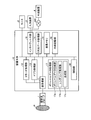
- FIG. 1 is a diagram for explaining a configuration example of an ultrasonic diagnostic apparatus according to the first embodiment.
- FIG. 2 is a diagram for explaining an example of a stereoscopic display monitor that performs stereoscopic display with nine parallax images.
- FIG. 3 is a diagram for explaining an example of the volume rendering process according to the first embodiment.
- FIG. 4 is a diagram for explaining the problems of the prior art.
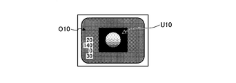
- FIG. 5A is a diagram (1) for explaining an example of the composite image group according to the first embodiment.
- FIG. 5B is a diagram (2) for explaining an example of the composite image group according to the first embodiment.
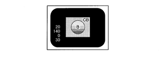
- FIG. 6A is a diagram (1) for explaining another example of the composite image group according to the first embodiment.
- FIG. 6B is a diagram (2) for explaining another example of the composite image group according to the first embodiment.
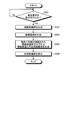
- FIG. 7 is a flowchart for explaining processing of the ultrasonic diagnostic apparatus according to the first embodiment.
- FIG. 8A is a diagram (1) for explaining a composite image group according to the second embodiment.
- FIG. 8B is a diagram (2) for explaining the composite image group according to the second embodiment.
- FIG. 9 is a flowchart for explaining processing of the ultrasonic diagnostic apparatus according to the second embodiment.
- FIG. 10A is a diagram (1) for explaining the control unit according to the third embodiment.
- FIG. 10B is a diagram (2) for explaining the control unit according to the third embodiment.
- FIG. 10C is a diagram (3) for explaining the control unit according to the third embodiment.
- FIG. 11 is a flowchart for explaining processing of the ultrasonic diagnostic apparatus according to the third embodiment.
- a “parallax image group” is an image generated by performing volume rendering processing by moving a viewpoint position by a predetermined parallax angle with respect to volume data. It is a group. That is, the “parallax image group” includes a plurality of “parallax images” having different “viewpoint positions”.
- the “parallax angle” is a predetermined position in the space represented by the volume data and an adjacent viewpoint position among the viewpoint positions set to generate the “parallax image group” (for example, the center of the space) It is an angle determined by.
- the “parallax number” is the number of “parallax images” necessary for stereoscopic viewing on the stereoscopic display monitor.
- the “9 parallax images” described below is a “parallax image group” composed of nine “parallax images”.
- the “two-parallax image” described below is a “parallax image group” composed of two “parallax images”.
- FIG. 1 is a diagram for explaining a configuration example of an ultrasonic diagnostic apparatus according to the first embodiment.
- the ultrasonic diagnostic apparatus according to the first embodiment includes an ultrasonic probe 1, a monitor 2, an input device 3, and an apparatus main body 10.
- the apparatus main body 10 is connected to the external apparatus 4 via the network 100.
- the ultrasonic probe 1 includes a plurality of piezoelectric vibrators, and the plurality of piezoelectric vibrators generate ultrasonic waves based on a drive signal supplied from a transmission / reception unit 11 included in the apparatus main body 10 described later.
- the ultrasonic probe 1 receives a reflected wave from the subject P and converts it into an electrical signal.
- the ultrasonic probe 1 includes a matching layer provided in the piezoelectric vibrator, a backing material that prevents propagation of ultrasonic waves from the piezoelectric vibrator to the rear, and the like.
- the ultrasonic probe 1 is detachably connected to the apparatus main body 10.
- the transmitted ultrasonic waves are transmitted from the ultrasonic probe 1 to the subject P
- the transmitted ultrasonic waves are reflected one after another at the discontinuous surface of the acoustic impedance in the body tissue of the subject P
- the ultrasonic probe is used as a reflected wave signal. 1 is received by a plurality of piezoelectric vibrators.
- the amplitude of the received reflected wave signal depends on the difference in acoustic impedance at the discontinuous surface where the ultrasonic wave is reflected.
- the reflected wave signal when the transmitted ultrasonic pulse is reflected by the moving blood flow or the surface of the heart wall depends on the velocity component of the moving object in the ultrasonic transmission direction due to the Doppler effect. And undergoes a frequency shift.
- the ultrasound probe 1 according to the first embodiment is an ultrasound probe capable of scanning the subject P in two dimensions with ultrasound and scanning the subject P in three dimensions.
- the ultrasonic probe 1 according to the first embodiment swings a plurality of ultrasonic transducers that scan the subject P in two dimensions at a predetermined angle (swing angle), thereby This is a mechanical scan probe that scans the specimen P in three dimensions.
- the ultrasonic probe 1 according to the first embodiment is a two-dimensional ultrasonic wave capable of ultrasonically scanning the subject P in three dimensions by arranging a plurality of ultrasonic transducers in a matrix. It is a probe.
- the two-dimensional ultrasonic probe can also scan the subject P two-dimensionally by focusing and transmitting ultrasonic waves.
- the input device 3 is connected to the device main body 10 via an interface unit 19 described later.
- the input device 3 includes a mouse, a keyboard, a button, a panel switch, a touch command screen, a foot switch, a trackball, and the like, accepts various setting requests from an operator of the ultrasonic diagnostic apparatus, and accepts it to the apparatus main body 10. Transfer various setting requests.
- the monitor 2 displays a GUI (Graphical User Interface) for an operator of the ultrasonic diagnostic apparatus to input various setting requests using the input device 3, and displays an ultrasonic image generated in the apparatus main body 10. To do.
- GUI Graphic User Interface
- the monitor 2 according to the first embodiment is a stereoscopically visible monitor (hereinafter, stereoscopic display monitor).
- stereoscopic display monitor a stereoscopically visible monitor
- the stereoscopic display monitor will be described.
- an apparatus that outputs an image to the general-purpose monitor needs to display two parallax images that can be viewed stereoscopically by the observer in parallel by the parallel method or the intersection method. is there.
- an apparatus that outputs an image to a general-purpose monitor uses an after-color method with an eyeglass that has a red cellophane attached to the left eye portion and a blue cellophane attached to the right eye portion. It is necessary to display a stereoscopically viewable image.
- a stereoscopic display monitor there is a monitor (hereinafter referred to as a “two-parallax monitor”) that enables stereoscopic viewing by binocular parallax by displaying a two-parallax image (also referred to as a binocular parallax image).
- the two-parallax monitor include a device that performs stereoscopic display using a shutter method, a device that performs stereoscopic display using a polarized glasses method, and a device that performs stereoscopic display using a parallax barrier method.
- a stereoscopic display monitor that allows a viewer to stereoscopically view a multi-parallax image such as a 9-parallax image with the naked eye by using a light controller such as a lenticular lens.
- a light controller such as a lenticular lens.
- Such a stereoscopic display monitor enables stereoscopic viewing based on binocular parallax, and also enables stereoscopic viewing based on motion parallax that also changes the image observed in accordance with the viewpoint movement of the observer.
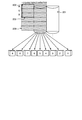
- FIG. 2 is a diagram for explaining an example of a stereoscopic display monitor that performs stereoscopic display with nine parallax images.
- a light beam controller is arranged on the front surface of a flat display surface 200 such as a liquid crystal panel.
- a vertical lenticular sheet 201 whose optical aperture extends in the vertical direction is attached to the front surface of the display surface 200 as a light beam controller.
- the display surface 200 has an aspect ratio of 3: 1 and pixels in which three sub-pixels of red (R), green (G), and blue (B) are arranged in the vertical direction.
- 202 are arranged in a matrix.
- the stereoscopic display monitor shown in FIG. 2 allocates and outputs nine pixels at the same position in nine parallax images to nine columns of pixels 202.
- the nine columns of pixels 202 constitute a unit pixel group 203 that simultaneously displays nine images with different viewpoint positions.
- the nine-parallax images simultaneously output as the unit pixel group 203 on the display surface 200 are emitted as parallel light by, for example, an LED (Light Emitting Diode) backlight, and further emitted in multiple directions by the vertical lenticular sheet 201.
- the light incident on the right eye and the left eye of the observer changes in conjunction with the position of the observer (viewpoint position).
- the observer can visually recognize the imaging target in three positions at each of the nine positions illustrated in FIG. 2, for example.
- the observer can view stereoscopically in a state of facing the object to be photographed at the position “5” shown in FIG.
- the stereoscopic display monitor described with reference to FIG. 2 is referred to as a 9-parallax monitor.
- the first embodiment is applicable regardless of whether the monitor 2 is a two-parallax monitor or a nine-parallax monitor.
- the monitor 2 is a 9-parallax monitor.
- the external device 4 is a device connected to the device main body 10 via an interface unit 19 described later.
- the external device 4 is a computer-readable storage device such as a hard disk, flexible disk, CD-ROM (Compact Disk Read Only Memory), MO (Magneto-Optical disk), DVD (Digital Versatile Disk).
- the external device 4 is a PC (Personal Computer) or tablet PC operated by a doctor or laboratory technician working in the hospital, a printer connected to a terminal device such as a PDA (Personal Digital Assistant), a mobile phone, or the above It is a general-purpose monitor.
- the apparatus main body 10 is an apparatus that generates ultrasonic image data based on the reflected wave received by the ultrasonic probe 1. Specifically, the apparatus body 10 according to the first embodiment generates three-dimensional ultrasonic image data (hereinafter referred to as volume data) based on the three-dimensional reflected wave data received by the ultrasonic probe 1. It can be generated.
- volume data three-dimensional ultrasonic image data
- the apparatus main body 10 includes a transmission / reception unit 11, a B-mode processing unit 12, a Doppler processing unit 13, a two-dimensional data processing unit 14, an image memory 15, an internal storage unit 16, a volume A data processing unit 17, a control unit 18, and an interface unit 19 are included.
- the transmission / reception unit 11 includes a trigger generation circuit, a delay circuit, a pulsar circuit, and the like, and supplies a drive signal to the ultrasonic probe 1.
- the pulsar circuit repeatedly generates rate pulses for forming transmission ultrasonic waves at a predetermined rate frequency.
- the delay circuit also sets the delay time for each piezoelectric vibrator necessary for determining the transmission directivity by focusing the ultrasonic wave generated from the ultrasonic probe 1 into a beam shape, and for each rate pulse generated by the pulser circuit. Give to.
- the trigger generation circuit applies a drive signal (drive pulse) to the ultrasonic probe 1 at a timing based on the rate pulse. In other words, the delay circuit arbitrarily adjusts the transmission direction from the piezoelectric vibrator surface by changing the delay time given to each rate pulse.
- the transmission / reception unit 11 has a function capable of instantaneously changing a transmission frequency, a transmission drive voltage, and the like in order to execute a predetermined scan sequence based on an instruction from the control unit 18 described later.
- the change of the transmission drive voltage is realized by a linear amplifier type transmission circuit capable of instantaneously switching its value or a mechanism for electrically switching a plurality of power supply units.
- the transmission / reception unit 11 includes an amplifier circuit, an A / D converter, an adder, and the like, and performs various processes on the reflected wave signal received by the ultrasonic probe 1 to generate reflected wave data.
- the amplifier circuit amplifies the reflected wave signal for each channel and performs gain correction processing.
- the A / D converter performs A / D conversion on the gain-corrected reflected wave signal and gives a delay time necessary for determining reception directivity to the digital data.
- the adder performs an addition process of the reflected wave signal processed by the A / D converter to generate reflected wave data. By the addition processing of the adder, the reflection component from the direction corresponding to the reception directivity of the reflected wave signal is emphasized.
- the transmission / reception unit 11 controls transmission directivity and reception directivity in transmission / reception of ultrasonic waves.
- the transmitting / receiving unit 11 transmits a three-dimensional ultrasonic beam from the ultrasonic probe 1 to the subject P, and from the three-dimensional reflected wave signal received by the ultrasonic probe 1. Three-dimensional reflected wave data is generated.
- the B-mode processing unit 12 receives the reflected wave data from the transmission / reception unit 11, performs logarithmic amplification, envelope detection processing, and the like, and generates data (B-mode data) in which the signal intensity is expressed by brightness. .
- the Doppler processing unit 13 performs frequency analysis on velocity information from the reflected wave data received from the transmission / reception unit 11, extracts blood flow, tissue, and contrast agent echo components due to the Doppler effect, and moving body information such as average velocity, dispersion, and power. Is generated for multiple points (Doppler data).
- the B-mode processing unit 12 and the Doppler processing unit 13 can process both two-dimensional reflected wave data and three-dimensional reflected wave data. That is, the B-mode processing unit 12 generates two-dimensional B-mode data from the two-dimensional reflected wave data, and generates three-dimensional B-mode data from the three-dimensional reflected wave data.
- the Doppler processing unit 13 generates two-dimensional Doppler data from the two-dimensional reflected wave data, and generates three-dimensional Doppler data from the three-dimensional reflected wave data.
- the two-dimensional data processing unit 14 generates “ultrasound image data for display” from the two-dimensional data generated by the B-mode processing unit 12 and the Doppler processing unit 13. That is, the two-dimensional data processing unit 14 generates two-dimensional B-mode image data in which the intensity of the reflected wave is expressed by luminance from the two-dimensional B-mode data generated by the B-mode processing unit 12.
- the two-dimensional data processing unit 14 is a two-dimensional color as an average velocity image, a dispersed image, a power image, or a combination image representing moving body information from the two-dimensional Doppler data generated by the Doppler processing unit 13. Generate Doppler image data.
- the two-dimensional data processing unit 14 converts (scan converts) the scanning line signal sequence of the ultrasonic scan into a scanning line signal sequence of a video format represented by a television or the like, thereby obtaining two-dimensional B-mode image data.
- “Ultrasonic image data for display” is generated from the two-dimensional color Doppler image data and output to the monitor 2.
- the two-dimensional data processing unit 14 generates “ultrasound image data for display” by performing coordinate conversion in accordance with the ultrasonic scanning mode by the ultrasonic probe 1.
- the two-dimensional data processing unit 14 generates a composite image in which character information, scales, body marks, and the like of various parameters are combined with display ultrasonic image data, and outputs the composite image to the monitor 2 as a video signal.
- an image composed of “character information of various parameters, scales, body marks, etc.” synthesized with the ultrasonic image for display is referred to as an “information image”.
- the image memory 15 is a memory that stores the image data generated by the two-dimensional data processing unit 14.
- the image memory 15 can also store data generated by the B-mode processing unit 12 and the Doppler processing unit 13.
- the internal storage unit 16 stores a control program for performing ultrasonic transmission / reception, image processing and display processing, diagnostic information (for example, patient ID, doctor's findings, etc.), various data such as a diagnostic protocol and various body marks. To do.
- the internal storage unit 16 is also used for storing image data stored in the image memory 15 as necessary.
- the volume data processing unit 17 generates ultrasonic image data for display from the three-dimensional data generated by the B mode processing unit 12 and the Doppler processing unit 13. As shown in FIG. 1, the volume data processing unit 17 includes a volume data generation unit 17a, a rendering processing unit 17b, and a synthesis unit 17c.
- the volume data generation unit 17a generates three-dimensional B-mode image data in which the intensity of the reflected wave is represented by luminance from the three-dimensional B-mode data generated by the B-mode processing unit 12.
- the volume data generation unit 17a is a three-dimensional color Doppler as an average velocity image, a dispersed image, a power image, or a combination image representing moving body information from the three-dimensional Doppler data generated by the Doppler processing unit 13. Generate image data.
- the volume data generation unit 17a generates “volume data” that is three-dimensional ultrasonic image data by performing coordinate conversion according to the ultrasonic scanning mode of the ultrasonic probe 1.
- the rendering processing unit 17b is a processing unit that performs rendering processing on the volume data in order to generate various images (two-dimensional images) for displaying the volume data on the monitor 2.
- the rendering processing performed by the rendering processing unit 17b includes processing for reconstructing an MPR image from volume data by performing a cross-section reconstruction method (MPR: Multi Planer Reconstruction).
- MPR Multi Planer Reconstruction
- the rendering processing performed by the rendering processing unit 17b includes processing for performing “Curved MPR” on volume data and processing for performing “Intensity Projection” on volume data.
- the rendering processing performed by the rendering processing unit 17b includes volume rendering processing for generating a two-dimensional image reflecting three-dimensional information.
- the rendering processing unit 17b performs a rendering process from a plurality of viewpoints on volume data that is three-dimensional ultrasound image data, and thereby a parallax image group that is a parallax image having a predetermined number of parallaxes. Is generated. Specifically, the rendering processing unit 17b generates a parallax image group by performing volume rendering processing on the volume data. More specifically, since the monitor 2 is a 9-parallax monitor, the rendering processing unit 17b performs 9-parallax images, which are 9 parallax images, by performing volume rendering processing from 9 viewpoints on the volume data. Generate.
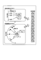
- FIG. 3 is a diagram for explaining an example of the volume rendering process according to the first embodiment.
- the rendering processing unit 17b accepts the parallel projection method as the rendering condition, and further, the reference viewpoint position (5) and the parallax angle “1”. ”Degree”. In such a case, the rendering processing unit 17b translates the viewpoint position from (1) to (9) so that the parallax angle is every “1 degree”, and uses the parallel projection method to change the parallax angle (between the gaze directions). Nine parallax images with different angles are generated by 1 degree.
- the rendering processing unit 17b sets a light source that emits parallel light rays from infinity along the line-of-sight direction.
- the rendering processing unit 17b accepts a perspective projection method as a rendering condition, and further, the reference viewpoint position (5) and the parallax angle “1”. ”Degree”. In such a case, the rendering processing unit 17b rotates the perspective position from (1) to (9) so that the parallax angle is “1 degree” around the center (center of gravity) of the volume data, and sees through.
- the rendering processing unit 17b sets a point light source or a surface light source that radiates light three-dimensionally around the line-of-sight direction at each viewpoint.
- the viewpoints (1) to (9) may be moved in parallel depending on the rendering conditions.
- the rendering processing unit 17b radiates light two-dimensionally radially around the line-of-sight direction with respect to the vertical direction of the displayed volume rendering image, and with respect to the horizontal direction of the displayed volume rendering image.
- the volume rendering process using both the parallel projection method and the perspective projection method may be performed by setting a light source that emits parallel light rays from infinity along the line-of-sight direction.
- the nine parallax images generated in this way are a group of parallax images. That is, the parallax image group is an ultrasonic image group for stereoscopic display generated from volume data.
- the nine parallax images are converted into intermediate images arranged in a predetermined format (for example, a lattice shape) by the control unit 18 to be described later, and are output to the monitor 2 as a stereoscopic display monitor.
- the monitor 2 Under the control of the control unit 18, the monitor 2 displays a parallax image group generated by the rendering processing unit 17 b, thereby displaying a stereoscopic image that is stereoscopically recognized by the observer (operator of the ultrasonic diagnostic apparatus). indicate.
- the volume data processing unit 17 displays “information image” indicating information (character information, scales, body marks, etc.) other than the parallax image group in the display parallax image group.
- a combined image group is generated and output to the monitor 2 as a video signal.
- volume data processing unit 17 is a processing unit installed in the volume data processing unit 17 in order to generate a composite image group.
- the processing of the combining unit 17c will be described in detail later.
- Various image data generated by the processing of the volume data processing unit 17 is stored in the image memory 15 or the internal storage unit 16.
- the control unit 18 controls the entire processing of the ultrasonic diagnostic apparatus. Specifically, the control unit 18 is based on various setting requests input from the operator via the input device 3 and various control programs and various data read from the internal storage unit 16. Controls the processing of the processing unit 12, Doppler processing unit 13, two-dimensional data processing unit 14, and volume data processing unit 17. Further, the control unit 18 controls the monitor 2 to display the ultrasonic image data for display stored in the image memory 15 and the internal storage unit 16. Further, the control unit 18 performs control so that the ultrasonic image data for display is output to the external device 4 via the interface unit 19 and the network 100.
- the interface unit 19 is an interface to the input device 3, the network 100, and the external device 4. Various setting information and various instructions from the operator received by the input device 3 are transferred to the control unit 18 by the interface unit 19. The image data output by the control of the control unit 18 is output from the interface unit 19 to the external device 4 via the network 100.
- the overall configuration of the ultrasonic diagnostic apparatus according to the first embodiment has been described above.
- the ultrasonic diagnostic apparatus according to the first embodiment generates volume data that is three-dimensional ultrasonic image data, and generates a parallax image group from the generated ultrasonic volume data.
- the ultrasound diagnostic apparatus according to the first embodiment displays a stereoscopic image that is stereoscopically recognized by the observer by displaying a parallax image group on the monitor 2.
- the image group that is actually displayed on the monitor 2 is a composite image group obtained by combining each of the parallax images constituting the parallax image group and the information image.
- the sense of depth of the stereoscopic image recognized by the observer by referring to the monitor 2 which is a stereoscopic display monitor is reduced due to the factors described below.
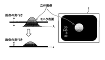
- FIG. 4 is a diagram for explaining the problems of the prior art.
- the problem described below is not only a stereoscopic image recognized by a parallax image group based on volume data generated by an ultrasonic diagnostic apparatus, but also a volume generated by a medical image diagnostic apparatus such as an X-ray CT apparatus or an MRI apparatus.
- the same problem arises in a stereoscopic image recognized by a parallax image group based on data.
- the background color of medical images is often black.
- the background color of the information image displayed together with the medical image is also generally black. That is, the background color of each of the parallax image group and the information image is the same black. Therefore, as shown in the right diagram of FIG. 4, the observer recognizes a stereoscopic image together with information such as characters in a black background on the surface of the monitor 2 (hereinafter referred to as the monitor surface). .
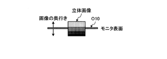
- the parallax image group is a three-dimensional object having a depth from a position protruding from the monitor surface to the viewer side to a position behind the monitor surface (see A in the figure). It is an image group generated so as to be recognized by an observer as an image.
- the stereoscopic image actually recognized by the observer is from the position protruding from the monitor surface to the observer side to the position of the monitor surface (see a in the figure).
- the stereoscopic image has only depth. That is, since the observer recognizes the position A of the stereoscopic image as the position a, the depth of the stereoscopic image is compressed as shown in FIG.
- the control unit 18 of the ultrasonic diagnostic apparatus avoids a reduction in the sense of depth of a stereoscopic medical image by performing the control described below.
- the control unit 18 can identify the first region displaying the parallax image group on the monitor 2 and the second region displaying the information image indicating information other than the parallax image group on the monitor 2.
- a composite image group of information images are controlled to be displayed on the monitor 2.
- the control unit 18 controls the monitor 2 to display a composite image group in which the background color of the first area and the background color of the second area are different.
- control unit 18 uses the background color of the first area and the background color of the second area as a composite image group of the parallax image group and the information image that can identify the first area and the second area. Control is performed so that the composition unit 17c generates a composite image group having different colors.
- 5A and 5B are diagrams for explaining an example of the composite image group according to the first embodiment.
- 6A and 6B are diagrams for explaining an example of each composite image group according to the first embodiment.
- the control unit 18 performs control so that a composite image group in which the background color of the first region is black and the background color of the second region is gray is displayed on the monitor 2.
- the combining unit 17c generates a combined image of the parallax image U10 whose background color is black and the information image O10 whose background color is gray, as shown in FIG. 5A.
- the parallax image U10 illustrated in FIG. 5A indicates one parallax image among nine parallax images in which the parallax angle between the images is, for example, “1 degree”.
- Nine combined images of the nine parallax images whose background color is black and the information image O10 whose background color is gray are generated.
- the composition unit 17c sets the background color of each of the nine parallax images displayed in the first area to black.
- the synthesizing unit 17c uses the nine parallax images generated by the rendering processing unit 17b as they are for subsequent processing.
- the synthesis unit 17c sets the background color of the nine parallax images generated by the rendering processing unit 17b to black and uses it for subsequent processing.
- the composition unit 17c generates an information image in which information such as character information is arranged in the second area set so as to surround the first area, and the color of the background portion other than the information is gray. Then, the synthesis unit 17c generates a synthesized image group including nine synthesized images by synthesizing each of the nine parallax images whose background color is black and the information image whose background color is gray.
- the control unit 18 converts the composite image group into the above-described intermediate image and displays it on the monitor 2.
- the observer of the monitor 2 recognizes character information drawn on the information image O10 with a gray background color.
- the observer of the monitor 2 recognizes the stereoscopic image displayed by the parallax image group with a black background color. Since the observer recognizes that gray is closer to itself than black, the depth of the stereoscopic image whose background color is black is maintained.
- the composite image group generated by the composite unit 17c is not limited to the composite image group illustrated in FIGS. 5A and 5B.
- the combining unit 17c keeps the background color of the information image black and sets the background color of the parallax image group to the complementary color “B” of the parallax image group as shown in FIG. 6A. CB "may be used.
- the background color of the parallax image group as a complementary color, the observer can identify the stereoscopic image and the information image.
- the composition unit 17 c further sets the background color of the parallax image group as the complementary color “CB” of the color “B” of the parallax image group as shown in FIG. It is also possible to use a composite image group in which the outline of the image is highlighted in black. By using the background color of the parallax image group as a complementary color and the outline of the parallax image group as black, the observer can recognize that the outline of the stereoscopic image in the first region is located behind the monitor surface, A stereoscopic image and an information image can be identified.
- 6A and 6B may be a case where the background color of the second area in which the information image is displayed is generated as an intermediate color between “B” and “CB”. good.
- FIG. 7 is a flowchart for explaining processing of the ultrasonic diagnostic apparatus according to the first embodiment.
- processing after volume data is generated and the generation conditions of the parallax image group such as the viewpoint position, the number of parallaxes, and the parallax angle for the volume data are set will be described.
- the ultrasonic diagnostic apparatus determines whether a stereoscopic image display request has been received from the operator via the input device 3 (step S ⁇ b> 101).
- the ultrasonic diagnostic apparatus stands by until a display request is received.
- Step S101 when a display request is received (Yes at Step S101), the rendering processing unit 17b generates a parallax image group with a black background color (Step S102), and the composition unit 17c An information image whose color is gray is generated (step S103). Specifically, the composition unit 17c generates an information image whose background color is gray according to the shape of the second region.
- the composition unit 17c generates a composite image group of the parallax image group and the information image in accordance with the size of the first area (step S104). Then, the monitor 2 displays the composite image group under the control of the control unit 18 (step S105), and ends the process.
- the control unit 18 displays the first area in which the parallax image group is displayed on the monitor 2 and the information image indicating information other than the parallax image group on the monitor 2.
- a “composite image group of a parallax image group and an information image” that allows the region to be identified is displayed. That is, in the first embodiment, the control unit 18 uses the background color of the first region and the second region as a composite image group of the parallax image group and the information image that can identify the first region and the second region.
- the composite unit 17 c is controlled so as to generate a composite image group having a color different from the background color of the background color, and is displayed on the monitor 2.
- control unit 18 is a composite image group of a parallax image group and an information image that can identify the first area and the second area, and the background color of the first area is black,
- the composite image group which is gray and background color is controlled to be generated by the combining unit 17c and displayed on the monitor 2.
- the observer may feel that the information image displayed in the second area is located on the monitor surface and feel that the background of the stereoscopic image displayed in the first area is behind the monitor surface. it can. Therefore, in the first embodiment, it is possible to avoid a reduction in the sense of depth of a stereoscopic medical image.
- combination part 17c which concerns on 1st Embodiment is performed by the two-dimensional data processing part 14 may be sufficient.
- the ultrasonic diagnostic apparatus according to the second embodiment is configured in the same manner as the ultrasonic diagnostic apparatus according to the first embodiment described with reference to FIG. 1, but the control process for the synthesis unit 17 c of the control unit 18 is performed. Different from the first embodiment. Hereinafter, this will be mainly described.
- the control unit 18 controls the monitor 2 to display a composite image group in which a frame line surrounding the boundary between the first area and the second area is drawn.
- 8A and 8B are diagrams for explaining a composite image group according to the second embodiment.
- composition unit 17c under the control of the control unit 18, draws a frame line in which the boundary between the first region and the second region is surrounded by a white double line as shown in FIG. 8A. Generate a group of images.
- the synthesizing unit 17c uses the nine parallax images generated by the rendering processing unit 17b as they are for subsequent processing.
- the combining unit 17c generates an information image in which character information and the like are arranged in the second region and the background portion other than the character information has a black color as in the conventional case.
- the synthesizing unit 17c synthesizes each of the nine parallax images and the information image, and further draws a white double line surrounding the outline of each of the nine parallax images, thereby forming the nine synthesized images.
- a composite image group is generated.
- the control unit 18 converts the composite image group into an intermediate image and displays it on the monitor 2. Thereby, as shown in FIG. 8B, the observer of the monitor 2 recognizes character information drawn on the information image divided by the frame line. Then, as shown in FIG. 8B, the observer of the monitor 2 recognizes the stereoscopic image divided by the frame line with a black background color. Since the observer can identify the information image and the stereoscopic image by the frame line, the depth of the stereoscopic image is maintained.
- the identification effect by such a frame line is called a sticking effect or a frame effect.
- a sticking effect or a frame effect.
- the object to be reproduced in three dimensions is divided by the image frame (frame line)
- the stereoscopic effect may be suppressed and the object may appear to be deformed.
- the control unit 18 sets the image frame (frame line) so that the monitor display surface and the image frame (frame line) appear at different positions, weakens the presence of the frame, and uncertains the display surface position. It is also possible to extend the screen size so as to be in a proper state, or to perform control based on the aerial image / aerial image method.
- an aerial image is an image in which a display image is formed in the air. When the aerial image is observed, the position of the display surface becomes indeterminate and the reproduction space is not fixed to the display surface. is there.
- An aerial image is an image formed by a multilayer display surface, image plane movement, or the like. When an aerial image is observed, the same effect as that obtained when an aerial image is observed can be obtained.
- FIG. 9 is a flowchart for explaining processing of the ultrasonic diagnostic apparatus according to the second embodiment.
- processing after volume data is generated and the generation conditions of the parallax image group such as the viewpoint position, the number of parallaxes, and the parallax angle for the volume data are set will be described.
- the ultrasonic diagnostic apparatus determines whether or not a stereoscopic image display request has been received from the operator via the input device 3 (step S201).
- the ultrasonic diagnostic apparatus waits until a display request is received.
- Step S202 when a display request is received (Yes at Step S202), the rendering processing unit 17b generates a parallax image group with a black background color (Step S202) under the control of the control unit 18, and the composition unit 17c An information image with a black color is generated (step S203). Specifically, the composition unit 17c generates an information image with a black background color according to the shape of the second region.
- the synthesizing unit 17c generates a combined image group of the parallax image group that matches the size of the first region and each of the parallax image group in which the border is drawn at the boundary and the information image (step S204). Then, the monitor 2 displays the composite image group under the control of the control unit 18 (step S205), and ends the process.
- control unit 18 controls the combining unit 17c to generate a combined image group in which a frame surrounding the boundary between the first region and the second region is drawn. And displayed on the monitor 2.
- the observer can distinguish the first area and the second area with a line. That is, in the second embodiment, even when the background color is the same color, it is possible to prevent the observer from recognizing that the stereoscopic image and the information image are at the same depth position. Therefore, also in the second embodiment, it is possible to avoid a reduction in the sense of depth of a stereoscopic medical image.
- combination part 17c which concerns on 2nd Embodiment is performed by the two-dimensional data processing part 14 may be sufficient.
- the observed image may be output as two-dimensional data.
- the stereoscopic image is an image recognized by displaying a plurality of parallax images.
- the output image looks double or is blurred. That is, a plurality of parallax images are not preferable as output images. Therefore, in order to output for printing or output for observation on a general-purpose monitor, an image on which a parallax image group is not superimposed is necessary.
- control unit 18 performs control so that image data of a predetermined viewpoint is extracted from the parallax image group recognized as a stereoscopic image and output to the external device 4.
- the output control performed by the control unit 18 includes the following two. That is, in the first output control, the control unit 18 extracts parallax image data from viewpoints positioned at the center of all viewpoints used when generating a parallax image group as image data of a predetermined viewpoint. Or in 2nd output control, the control part 18 extracts the parallax image applicable to the stereo image which the observer who refers the monitor 2 observes as image data of a predetermined viewpoint.
- control unit 18 selects the corresponding image data and outputs it to the external device 4.
- control unit 18 causes the rendering processing unit 17 b to generate the image data of the predetermined viewpoint and output it to the external device 4.
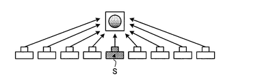
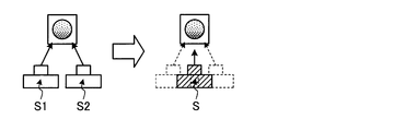
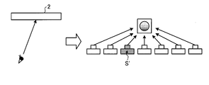
- FIGS. 10A, 10B, and 10C are diagrams for explaining a control unit according to the third embodiment.
- the control unit 18 selects the parallax image of the viewpoint S at the center position of all viewpoints from among the nine parallax images recognized as a stereoscopic image.
- the parallax image data of the viewpoint S is extracted and output to the external device 4.
- the extraction process executed by the control unit 18 is an existing parallax. It can be executed by selecting from a group of images.
- the number of parallaxes is an even number as in the case where the monitor 2 is a two-parallax monitor, there is no parallax image of the viewpoint at the center position of all viewpoints.
- the control unit 18 sets the viewpoint S between the viewpoints S1 and S2 adjacent to the center position of all viewpoints. Then, as illustrated in FIG. 10B, the control unit 18 controls the rendering processing unit 17b to generate a parallax image from the viewpoint S by performing volume rendering processing from the volume data. Then, the control unit 18 outputs the newly generated parallax image data of the viewpoint S to the external device 4.
- the control unit 18 When performing the second output control, the control unit 18 observes the monitor 2 as shown in FIG. 10C in order to specify the parallax image corresponding to the stereoscopic image observed by the observer who refers to the monitor 2. Acquire the gaze direction of the person. For example, the control unit 18 acquires the line-of-sight direction of the observer with respect to the monitor 2 using a camera having a face recognition function attached to the monitor 2. For example, the camera tracks (tracks) the face of the observer in the real space by the face recognition function, and further determines the line-of-sight direction with respect to the monitor 2 of the observer from the recognized face direction. The line-of-sight direction acquired by the camera is transferred to the control unit 18.
- the control part 18 extracts the parallax image applicable to an observer's gaze direction from a parallax image group.
- the data of the corresponding parallax image is selected and the external device 4 is selected. Output to.
- the control unit 18 sets the viewpoint S ′ for the volume data. Then, the control unit 18 controls the rendering processing unit 17b so as to generate a parallax image from the newly set viewpoint S 'by performing volume rendering processing from the volume data. Then, the control unit 18 outputs the newly generated parallax image data of the viewpoint S ′ to the external device 4.
- control unit 18 may also be a case where the extraction target of output parallax image data is the composite image group described in the first embodiment or the second embodiment. good.
- the control unit 18 causes the rendering processing unit 17b to newly generate a parallax image of the predetermined viewpoint, and further causes the synthesis unit 17c to generate the parallax image of the predetermined viewpoint and the information image. A new composite image is generated.
- FIG. 11 is a flowchart for explaining processing of the ultrasonic diagnostic apparatus according to the third embodiment.
- the ultrasonic diagnostic apparatus determines whether or not an output request for general-purpose monitors has been received from the operator via the input device 3 (step S301).
- the ultrasonic diagnostic apparatus stands by until an output request is received.
- Step S301 when an output request is received (Yes at Step S301), the control unit 18 determines whether there is data corresponding to the image data for output (Step S302). Here, when it exists (Yes at Step S302), the control unit 18 selects data corresponding to the image data for output (Step S303). When the composite image group is an extraction target, the data selected in step S303 is composite image data.
- Step S304 the rendering processing unit 17b generates data corresponding to the image data for output under the control of the control unit 18. If the composite image group is an extraction target, in step S304, new composite image data is generated by the rendering processing unit 17b and the composite unit 17c.
- control unit 18 After the process of step S303 or step S304, the control unit 18 outputs the image data for output to the external device 4 (step S305), and ends the process.
- control unit 18 performs control so that image data of a predetermined viewpoint is extracted from the parallax image group recognized as a stereoscopic image and output to the external device 4. Therefore, in the third embodiment, a parallax image group from multiple viewpoints can be output instead of an image from one viewpoint.
- the image data of the predetermined viewpoint is one parallax image or one composite image at one viewpoint.
- the image data output to the external device 4 by the processing of the control unit 18 according to the third embodiment may be a plurality of parallax images or a plurality of synthesized images. That is, the third embodiment is not limited to a case where the predetermined viewpoint is composed of one viewpoint, but may be a case where the predetermined viewpoint is composed of a plurality of viewpoints.
- the monitor 2 is a 9-parallax monitor and the monitor connected to the external device 4 is a 9-parallax monitor.
- the control unit 18 outputs nine parallax images and nine synthesized images displayed as a stereoscopic image on the monitor 2 to the external device 4 as image data of a predetermined viewpoint.
- the monitor 2 is a 9-parallax monitor
- the monitor connected to the external device 4 is a 5-parallax monitor that displays a stereoscopic image by displaying 5 parallax images.
- the control unit 18 outputs five image data selected from nine parallax images and nine composite images displayed as a stereoscopic image on the monitor 2 to the external device 4 as image data of a predetermined viewpoint.
- the control unit 18 outputs a parallax image group from five viewpoints centered on the viewpoint S illustrated in FIG. 10A to the external device 4 as image data of a predetermined viewpoint.
- the control unit 18 outputs a parallax image group from five viewpoints centered on the viewpoint S ′ illustrated in FIG. 10B to the external device 4 as image data of a predetermined viewpoint.
- the control unit 18 causes the volume data processing unit 17 to newly generate a five-parallax image or five composite images displayed as a stereoscopic image on the five-parallax monitor, and then outputs the generated image to the external device 4.
- the control unit 18 outputs two pieces of image data selected from nine parallax images displayed as a stereoscopic image on the monitor 2 and nine composite images to the external device 4 as image data of a predetermined viewpoint.
- the control unit 18 outputs the parallax image from the viewpoint S illustrated in FIG. 10A and the parallax image from the viewpoint positioned on the right side of the viewpoint S to the external device 4 as image data of a predetermined viewpoint.
- control unit 18 causes the volume data processing unit 17 to newly generate a two-parallax image or two composite images displayed as a stereoscopic image on the two-parallax monitor, and then outputs the two-parallax image to the external device 4.
- the monitor 2 is a 9-parallax monitor
- the monitor connected to the external device 4 is an 18-parallax monitor that displays a stereoscopic image by displaying 18 parallax images.
- the control unit 18 selects nine parallax images or nine composite images displayed as a stereoscopic image on the monitor 2. Further, the control unit 18 newly sets the positions of nine viewpoints in addition to the viewpoints used for generating nine parallax images and nine composite images displayed as a stereoscopic image on the monitor 2. Then, the control unit 18 causes the volume data processing unit 17 to generate nine parallax images and nine synthesized images using the nine newly set viewpoints.
- control unit 18 outputs 18 parallax images and 18 synthesized images to the external device 4 as image data of a predetermined viewpoint.
- the control unit 18 performs the above-described processing by acquiring information about the stereoscopic viewing style of the monitor connected to the external device 4 from the external device 4 from the external device 4 or the operator of the external device 4.
- the monitor connected to the external device 4 is a 9-parallax monitor and the reference viewpoint position is received from the operator of the external device 4.
- the control unit 18 outputs these image data to the external device 4 as image data of a predetermined viewpoint.
- the control unit 18 displays the nine parallax images centered on the reference viewpoint position received from the operator of the external device 4 and the nine synthesized images.
- the image is output to the external device 4.
- the information received from the operator of the external device 4 may include information on the parallax angle in addition to the reference viewpoint position.
- control unit 18 uses these image data as a predetermined viewpoint. Output as image data. If the image data that matches the conditions received from the operator of the external apparatus 4 has not been generated in the apparatus main body 10, the control section 18 causes the volume data processing section 17 to generate the corresponding image data, and 4 is output.
- the monitor 2 is a 9-parallax monitor has been described.
- the first to third embodiments described above can be applied even when the monitor 2 is a two-parallax monitor.
- the first to third embodiments described above the case where the image displayed on the monitor 2 is a volume rendering image has been described.
- the first to third embodiments described above are applicable even when the image displayed on the monitor 2 is an MPR image generated by MPR from volume data.
- the ultrasonic diagnostic apparatus which is a medical image diagnostic apparatus
- a composite image group for preventing a feeling of depth from being displayed or data for outputting a stereoscopic image are displayed.
- the case of extracting the file has been described.
- the processing described in the first to third embodiments may be executed in a medical image diagnostic apparatus capable of generating volume data such as an X-ray CT apparatus or an MRI apparatus. .
- the processes described in the first to third embodiments may be executed by an image processing apparatus installed independently of the medical image diagnostic apparatus.
- the image processing apparatus having the functions of the volume data processing unit 17 and the control unit 18 shown in FIG. 1 manages a database of PACS (Picture Archiving and Communication Systems), which is a system for managing various medical image data.
- the volume data which is three-dimensional medical image data, is received from a database or the like of an electronic medical record system that manages an electronic medical record to which a medical image is attached, and the processing described in the first to third embodiments is performed. It may be the case.
Landscapes
- Life Sciences & Earth Sciences (AREA)
- Health & Medical Sciences (AREA)
- Engineering & Computer Science (AREA)
- Physics & Mathematics (AREA)
- Surgery (AREA)
- Animal Behavior & Ethology (AREA)
- Veterinary Medicine (AREA)
- Public Health (AREA)
- Biophysics (AREA)
- Nuclear Medicine, Radiotherapy & Molecular Imaging (AREA)
- Pathology (AREA)
- Radiology & Medical Imaging (AREA)
- Biomedical Technology (AREA)
- Heart & Thoracic Surgery (AREA)
- Medical Informatics (AREA)
- Molecular Biology (AREA)
- General Health & Medical Sciences (AREA)
- Multimedia (AREA)
- Signal Processing (AREA)
- General Engineering & Computer Science (AREA)
- Computer Graphics (AREA)
- General Physics & Mathematics (AREA)
- Software Systems (AREA)
- Computer Hardware Design (AREA)
- Theoretical Computer Science (AREA)
- Computer Vision & Pattern Recognition (AREA)
- Ultra Sonic Daignosis Equipment (AREA)
- Apparatus For Radiation Diagnosis (AREA)
- Magnetic Resonance Imaging Apparatus (AREA)
- Processing Or Creating Images (AREA)
- Image Generation (AREA)
- Testing, Inspecting, Measuring Of Stereoscopic Televisions And Televisions (AREA)
Abstract
L'appareil de diagnostic à ultrasons, qui est un mode de réalisation de l'appareil de diagnostic par image médicale selon l'invention est équipé d'une unité de rendu (17b), d'un moniteur (2) et d'une unité de commande (18). L'unité de rendu (17b) génère une série d'images parallaxes, qui correspond à un nombre prescrit d'images parallaxes, par application d'un rendu sur des données volumétriques, qui sont des données d'images médicales tridimensionnelles, issues depuis de multiples points de vue. Le moniteur (2) affiche les images stéréoscopiques que l'observateur perçoit par stéréoscopie par affichage de la série d'images parallaxes. L'unité de commande (18) exerce un contrôle de façon qu'une série d'images combinées constituées de la série d'images parallaxes et d'une image d'information, qui permet de distinguer une première région montrant la série d'images parallaxes sur le moniteur (2) et une seconde région montrant une image d'information représentant une information autre que la série d'images parallaxes sur le moniteur (2), s'affiche sur le moniteur (2).
Priority Applications (2)
| Application Number | Priority Date | Filing Date | Title |
|---|---|---|---|
| CN201280000691.4A CN102893306B (zh) | 2011-05-19 | 2012-05-11 | 医用图像诊断装置及图像处理装置 |
| US14/067,367 US9282324B2 (en) | 2011-05-19 | 2013-10-30 | Medical image diagnosis apparatus and image processing apparatus |
Applications Claiming Priority (2)
| Application Number | Priority Date | Filing Date | Title |
|---|---|---|---|
| JP2011112299 | 2011-05-19 | ||
| JP2011-112299 | 2011-05-19 |
Related Child Applications (1)
| Application Number | Title | Priority Date | Filing Date |
|---|---|---|---|
| US14/067,367 Continuation US9282324B2 (en) | 2011-05-19 | 2013-10-30 | Medical image diagnosis apparatus and image processing apparatus |
Publications (1)
| Publication Number | Publication Date |
|---|---|
| WO2012157585A1 true WO2012157585A1 (fr) | 2012-11-22 |
Family
ID=47176903
Family Applications (1)
| Application Number | Title | Priority Date | Filing Date |
|---|---|---|---|
| PCT/JP2012/062216 Ceased WO2012157585A1 (fr) | 2011-05-19 | 2012-05-11 | Appareil de diagnostic par image médicale et appareil de traitement d'image |
Country Status (4)
| Country | Link |
|---|---|
| US (1) | US9282324B2 (fr) |
| JP (1) | JP6058282B2 (fr) |
| CN (1) | CN102893306B (fr) |
| WO (1) | WO2012157585A1 (fr) |
Families Citing this family (8)
| Publication number | Priority date | Publication date | Assignee | Title |
|---|---|---|---|---|
| JP6299194B2 (ja) * | 2013-12-12 | 2018-03-28 | コニカミノルタ株式会社 | 超音波診断装置、及び超音波画像表示方法 |
| US10547822B2 (en) | 2014-05-21 | 2020-01-28 | Sony Corporation | Image processing apparatus and method to generate high-definition viewpoint interpolation image |
| EP3220828B1 (fr) | 2014-11-18 | 2021-12-22 | C.R. Bard, Inc. | Système d'imagerie à ultrasons ayant une présentation d'image automatique |
| US10646201B2 (en) | 2014-11-18 | 2020-05-12 | C. R. Bard, Inc. | Ultrasound imaging system having automatic image presentation |
| US9796492B2 (en) | 2015-03-12 | 2017-10-24 | Graco Minnesota Inc. | Manual check valve for priming a collapsible fluid liner for a sprayer |
| JP6610185B2 (ja) * | 2015-11-12 | 2019-11-27 | コニカミノルタ株式会社 | 画像処理装置 |
| CN113453607B (zh) * | 2019-03-08 | 2024-02-13 | 富士胶片株式会社 | 医用图像处理装置及方法 |
| CN115739435A (zh) | 2019-05-31 | 2023-03-07 | 固瑞克明尼苏达有限公司 | 手持式流体喷雾器 |
Citations (3)
| Publication number | Priority date | Publication date | Assignee | Title |
|---|---|---|---|---|
| JP2003339703A (ja) * | 2003-05-26 | 2003-12-02 | Olympus Optical Co Ltd | 超音波画像信号処理装置及び超音波画像信号処理システム |
| WO2009057409A1 (fr) * | 2007-10-30 | 2009-05-07 | Olympus Corporation | Dispositif endoscopique |
| WO2010095403A1 (fr) * | 2009-02-17 | 2010-08-26 | パナソニック株式会社 | Dispositif de lecture, procédé de lecture et programme |
Family Cites Families (9)
| Publication number | Priority date | Publication date | Assignee | Title |
|---|---|---|---|---|
| JP2000078611A (ja) | 1998-08-31 | 2000-03-14 | Toshiba Corp | 立体映像受信装置及び立体映像システム |
| JP2001326947A (ja) | 2000-05-12 | 2001-11-22 | Sony Corp | 立体画像表示装置 |
| JP4222875B2 (ja) | 2003-05-28 | 2009-02-12 | 三洋電機株式会社 | 立体映像表示装置及びプログラム |
| CN100459719C (zh) * | 2003-09-04 | 2009-02-04 | 株式会社东芝 | 三维影像显示装置和方法及三维显示用影像数据生成方法 |
| JP4002875B2 (ja) * | 2003-09-16 | 2007-11-07 | 株式会社東芝 | 立体画像表示装置 |
| JP2009077234A (ja) * | 2007-09-21 | 2009-04-09 | Toshiba Corp | 三次元画像処理装置、方法及びプログラム |
| US9256982B2 (en) * | 2010-03-17 | 2016-02-09 | Microsoft Technology Licensing, Llc | Medical image rendering |
| JP5572437B2 (ja) * | 2010-03-29 | 2014-08-13 | 富士フイルム株式会社 | 3次元医用画像に基づいて立体視用画像を生成する装置および方法、並びにプログラム |
| JP5673008B2 (ja) * | 2010-08-11 | 2015-02-18 | ソニー株式会社 | 画像処理装置、立体画像表示装置および立体画像表示システム、ならびに立体画像表示装置の視差ずれ検出方法および立体画像表示装置の製造方法 |
-
2012
- 2012-05-11 WO PCT/JP2012/062216 patent/WO2012157585A1/fr not_active Ceased
- 2012-05-11 CN CN201280000691.4A patent/CN102893306B/zh not_active Expired - Fee Related
- 2012-05-11 JP JP2012109962A patent/JP6058282B2/ja not_active Expired - Fee Related
-
2013
- 2013-10-30 US US14/067,367 patent/US9282324B2/en not_active Expired - Fee Related
Patent Citations (3)
| Publication number | Priority date | Publication date | Assignee | Title |
|---|---|---|---|---|
| JP2003339703A (ja) * | 2003-05-26 | 2003-12-02 | Olympus Optical Co Ltd | 超音波画像信号処理装置及び超音波画像信号処理システム |
| WO2009057409A1 (fr) * | 2007-10-30 | 2009-05-07 | Olympus Corporation | Dispositif endoscopique |
| WO2010095403A1 (fr) * | 2009-02-17 | 2010-08-26 | パナソニック株式会社 | Dispositif de lecture, procédé de lecture et programme |
Also Published As
| Publication number | Publication date |
|---|---|
| CN102893306A (zh) | 2013-01-23 |
| US20140055452A1 (en) | 2014-02-27 |
| JP6058282B2 (ja) | 2017-01-11 |
| US9282324B2 (en) | 2016-03-08 |
| JP2012254288A (ja) | 2012-12-27 |
| CN102893306B (zh) | 2016-11-16 |
Similar Documents
| Publication | Publication Date | Title |
|---|---|---|
| JP6058283B2 (ja) | 超音波診断装置 | |
| JP6058282B2 (ja) | 医用画像診断装置及び画像処理装置 | |
| US9479753B2 (en) | Image processing system for multiple viewpoint parallax image group | |
| US9426443B2 (en) | Image processing system, terminal device, and image processing method | |
| JP2013017577A (ja) | 画像処理システム、装置、方法及び医用画像診断装置 | |
| US10226231B2 (en) | Ultrasonic diagnostic apparatus and image processing apparatus | |
| CN102892017B (zh) | 图像处理系统、装置、方法以及医用图像诊断装置 | |
| WO2012137821A1 (fr) | Système de traitement d'image, appareil, procédé et programme | |
| JP5797485B2 (ja) | 画像処理装置、画像処理方法及び医用画像診断装置 | |
| CN102985013B (zh) | 医用图像诊断装置、图像处理装置以及超声波诊断装置 | |
| US9210397B2 (en) | Image processing system, apparatus, and method | |
| KR20160014933A (ko) | 초음파 장치 및 그 제어방법 | |
| JP2013121453A (ja) | 超音波診断装置及び画像処理装置 | |
| JP2013123227A (ja) | 画像処理システム、装置、方法及び医用画像診断装置 | |
| JP6005913B2 (ja) | 報知装置、報知方法及び医用画像診断装置 | |
| JP2013097772A (ja) | 医用画像診断装置及び画像処理装置 | |
| JP5835975B2 (ja) | 画像処理システム、装置、方法及び医用画像診断装置 | |
| JP2013026792A (ja) | 画像処理装置、画像処理方法、画像処理システム及び医用画像診断装置 | |
| JP5835980B2 (ja) | 画像処理システム、装置、方法及び医用画像診断装置 | |
| JP6087618B2 (ja) | 画像処理システムおよび画像処理方法 | |
| JP2013021459A (ja) | 画像処理装置、画像処理方法、画像処理システム及び医用画像診断装置 | |
| JP2012231235A (ja) | 画像処理システム、装置、方法及びプログラム |
Legal Events
| Date | Code | Title | Description |
|---|---|---|---|
| WWE | Wipo information: entry into national phase |
Ref document number: 201280000691.4 Country of ref document: CN |
|
| 121 | Ep: the epo has been informed by wipo that ep was designated in this application |
Ref document number: 12786004 Country of ref document: EP Kind code of ref document: A1 |
|
| NENP | Non-entry into the national phase |
Ref country code: DE |
|
| 122 | Ep: pct application non-entry in european phase |
Ref document number: 12786004 Country of ref document: EP Kind code of ref document: A1 |