WO2012157622A1 - Bougie de préchauffage - Google Patents
Bougie de préchauffage Download PDFInfo
- Publication number
- WO2012157622A1 WO2012157622A1 PCT/JP2012/062351 JP2012062351W WO2012157622A1 WO 2012157622 A1 WO2012157622 A1 WO 2012157622A1 JP 2012062351 W JP2012062351 W JP 2012062351W WO 2012157622 A1 WO2012157622 A1 WO 2012157622A1
- Authority
- WO
- WIPO (PCT)
- Prior art keywords
- power supply
- shaft
- heater
- glow plug
- insulating member
- Prior art date
- Legal status (The legal status is an assumption and is not a legal conclusion. Google has not performed a legal analysis and makes no representation as to the accuracy of the status listed.)
- Ceased
Links
Images


Classifications
-
- G—PHYSICS
- G01—MEASURING; TESTING
- G01M—TESTING STATIC OR DYNAMIC BALANCE OF MACHINES OR STRUCTURES; TESTING OF STRUCTURES OR APPARATUS, NOT OTHERWISE PROVIDED FOR
- G01M15/00—Testing of engines
- G01M15/04—Testing internal-combustion engines
- G01M15/08—Testing internal-combustion engines by monitoring pressure in cylinders
-
- F—MECHANICAL ENGINEERING; LIGHTING; HEATING; WEAPONS; BLASTING
- F23—COMBUSTION APPARATUS; COMBUSTION PROCESSES
- F23Q—IGNITION; EXTINGUISHING-DEVICES
- F23Q7/00—Incandescent ignition; Igniters using electrically-produced heat, e.g. lighters for cigarettes; Electrically-heated glowing plugs
- F23Q7/001—Glowing plugs for internal-combustion engines
- F23Q2007/004—Manufacturing or assembling methods
- F23Q2007/005—Manufacturing or assembling methods pressure sensors
Definitions
- the present invention relates to a glow plug that is electrically heated.
- a glow plug that assists in starting an internal combustion engine such as a diesel engine is known.
- the glow plug is provided in the housing, a housing that is inserted and fixed in a through hole formed in the cylinder of the engine, a heater that protrudes from the front end of the housing into the combustion chamber (or auxiliary combustion chamber) of the cylinder, And a power supply shaft which is a conductor for supplying power from an external power source to the heater.
- the heater is supplied with electric power from the power source to generate heat, and heats the combustion chamber to assist in starting the engine.
- the present invention has been made to solve the above-described problems, and an object of the present invention is to provide a technique for expanding the mounting area of a circuit for pressure detection while preventing an increase in the size of a glow plug.
- an aspect of the present invention is provided with a heater energization shaft that supplies power to a heater, and an axial end portion of the heater energization shaft, and the pressure that the heater energization shaft receives in the axial direction.
- a pressure detecting element for converting the electric signal into an electric signal ; and an insulating first insulating member that surrounds an outer periphery of the pressure detecting element with respect to the shaft and projects a signal output terminal of the pressure detecting element toward the outer peripheral side of the shaft
- a power supply wiring provided on the outer peripheral side of the first insulating member with respect to the shaft, connected to the heater energizing shaft and supplying power to the heater, and an outer periphery of the power supply wiring with respect to the shaft
- a signal processing circuit that is connected to the signal output terminal and processes an electrical signal of the pressure detection terminal, and is provided between the power supply wiring and the signal processing circuit,
- the a No. processing circuit and the power supply wiring is a glow plug and a second insulating member for insulating.
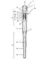
- FIG. 1 is a perspective view of the glow plug
- FIG. 2 is a plan view of the glow plug
- FIG. 3 is a front sectional view of the glow plug
- FIG. 4 is a left side sectional view of the glow plug.
- FIG. 3 shows a cross section taken along arrow III-III in FIG. 2
- FIG. 4 shows a cross section taken along arrow IV-IV in FIG.
- One end of this glow plug is inserted into a combustion chamber of a cylinder (not shown).
- one end (the lower end in FIG. 1) arranged in the combustion chamber is referred to as a distal end
- the other end (the upper end in FIG. 1) is referred to as a proximal end.
- This glow plug has a cylindrical housing 1, a heater 2 with a distal end protruding outside the housing 1, and a proximal end located within the housing 1, and is provided within the housing 1 with the distal end of the heater 2.
- the power supply shaft 3 connected to the base end, the sensor unit 4 provided in the housing 1 with the tip connected to the base end of the power supply shaft 3, and the tip provided in the housing 1
- the spacer 5 that is in contact with the base end of the sensor unit 4, the screw 6 that is fixed to the base end portion of the housing 1 and whose tip is in contact with the base end of the spacer 5, and the interior of the spacer 5 and the screw 6
- a power supply line 7 extending from the tip of the spacer 5 to the base end of the screw 6.
- the heater 2, the power supply shaft 3, the spacer 5, and the screw 6 have a common central axis.
- the base end side of the power supply wiring 7 is connected to a power supply (not shown).
- the housing 1 includes a distal end portion 11 that is located at the distal end of the housing 1 and has an opening, a male screw portion 12 that has a distal end connected to the proximal end of the distal end portion 11 and has a male screw formed on the outer periphery thereof, Is connected to the base end of the male screw portion 12 and the shaft storage portion 13 through which the power supply shaft 3 passes through the hollow portion, and the tip is connected to the base end of the shaft storage portion 13 and passes through the sensor unit 4 through the hollow portion.
- the sensor unit storage unit 14 includes a tool engagement unit 15 having a distal end connected to the proximal end of the sensor unit storage unit 14 and positioned at the proximal end of the housing 1.
- a female screw is formed on the inner peripheral wall of the through hole of the cylinder, and the male screw part 12 is screwed into the female screw. Furthermore, the outer peripheral wall of the tool engaging portion 15 forms a hexagonal column with the central axis as an axis, and can engage with a tool such as a spanner.
- the male screw portion 12 is obtained by inserting the heater 2 and the tip portion 11 into the combustion chamber from the through-hole of the cylinder and rotating the tool engaging portion 15 around the central axis using a tool. Is fastened to the female screw portion, and the glow plug is fixed to the cylinder.
- a female screw is formed on the inner peripheral wall of the tool engaging portion 15, and a male screw is formed on the outer peripheral wall of the screw 6 to be engaged with the female screw. Furthermore, two flat surfaces that can engage with a tool such as a spanner are formed on the outer peripheral wall of the base end of the screw 6.
- An opening for extending a part of the sensor unit 4 is formed on the side surface of the sensor unit storage portion 14, and the opening is closed by an adapter 14a.
- the heater 2 protrudes from the opening of the tip 11 into the combustion chamber.
- the heater 2 in this example is a sheath heater.
- the heater 2 includes a tube 2a that forms an outer wall, a spiral heating wire 2b provided on the tube 2a, and an insulator 2c filled in the tube 2a.
- One end of the heating wire 2b is connected to the tip of the power supply shaft 3, and the other end of the heating wire 2b is grounded by being connected to the cylinder through the housing 1.
- other methods such as a ceramic heater can be applied to the heater 2.
- An O-ring 21 is provided on the base end side of the heater 2 on the outer periphery of the power supply shaft 3. Since the outer periphery of the O-ring 21 is in contact with the inner peripheral surface of the housing 1, the combustion gas in the combustion chamber is prevented from entering the proximal end side of the housing 1. Depending on the attachment structure of the heater 2 to the housing 1, the intrusion of combustion gas can be prevented without using the O-ring 21.
- the housing 1 and the power supply shaft 3 are separated from each other and insulated.
- FIG. 5 is a front view of the sensor unit 4
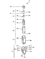
- FIG. 6 is an exploded perspective view of the sensor unit 4
- FIG. 7 is an exploded perspective view of the sensor unit 4 viewed from another direction.
- the sensor unit 4 includes an electrode 31 whose front end is in contact with the bottom surface of the guide 41, a pressure detection element 32 whose front surface is in contact with the proximal end of the electrode 31, and a distal end that is the proximal end of the pressure detection element 32.
- An electrode 33 that is in contact with the side surface, a cap 34 whose tip is in contact with the base end of the electrode 33, and the outer periphery of each of the electrode 31, the pressure detection element 32, and the electrode 33 with respect to the central axis.
- Each of the electrode 31, the pressure detection element 32, the electrode 33, and the cap 34 is provided on the central axis.
- the guide 41 is an insulator formed in a hollow cylindrical shape with the central axis as an axis.
- a hook-like clip 41 b is provided at the base end portion of the guide 41.
- the clip 41b locks the base end of the cap 34, the power supply shaft 3 comes into contact with the distal end of the case 43, and the bottom surface of the case 43 comes into contact with the distal end side of the electrode 31, whereby the electrode 31, the pressure detecting element 32,
- the electrode 33 is held in the guide 41.
- the guide 41 is formed with a slit 41a (first slit) in a direction parallel to the central axis. At the distal end of the guide 41, the distal end of the slit 41a is closed, and at the proximal end of the guide 41, the proximal end of the slit 41a is open.
- the ring 42 is a conductor formed in a hollow cylindrical shape with the central axis as an axis. Further, a slit 42a (second slit) in a direction parallel to the central axis is formed at a position of the ring 42 that overlaps the slit 41a.
- the distal end of the slit 42 a is open at the distal end of the ring 42, and the proximal end of the slit 42 a is open at the proximal end of the ring 42. That is, the cross section perpendicular to the central axis of the ring 42 has a shape (C-shape) in which a part of the ring is missing.
- a notch 42 b is formed at the tip of the ring 42.
- the outer diameter of the base end of the power supply shaft 3 is greater than or equal to the inner diameter of the tip of the ring 42.
- the diameter of the notch 42b is expanded by inserting the power supply shaft 3 into the tip of the ring 42, and the tip of the ring 42 covers the base end of the power supply shaft 3.
- the base end of the power supply shaft 3 and the tip of the ring 42 are in surface contact and connected by a snap fit.
- the base end of the ring 42 is connected to the tip of the power supply wiring 7, so that power from the power supply is supplied to the heater 2 via the power supply wiring 7, the ring 42, and the power supply shaft 3. Since the ring 42 covers the outer periphery of the guide 41 with respect to the central axis, the cross-sectional area of the conductor through which current flows to the heater 2 can be ensured. In addition, since the base end of the power supply shaft 3 and the tip of the ring 42 are in surface contact, the cross-sectional area of the conductor through which current flows to the heater 2 can be secured.
- the case 43 is an insulator formed in a cylindrical body.
- a cross section perpendicular to the central axis of the inner peripheral wall of the case 43 has a shape (D-shaped) in which a part of a circle is cut off by a straight line, and engages with the outer peripheral wall of the ring 42. This engagement prevents the ring 42 from rotating about the central axis.
- a slit 43a (third slit) in a direction parallel to the central axis is formed in the case 43 at a position overlapping the slit 41a. The distal end of the slit 43 a is closed at the distal end of the case 43, and the proximal end of the slit 43 a is open at the proximal end of the case 43.
- a slit 43a that overlaps the slit 42a is formed on a plane located on the outer peripheral side of the slit 42a, and substrate pasting portions 43c and 43e are formed on two planes adjacent to the slit 43a, respectively.
- a substrate pasting portion 43d is formed on the plane opposite to the slit 43a.
- the electrode 31 has a contact point 31a that is disposed on the central axis and abuts on the tip side surface of the pressure detection element 32, and a pin 31b that protrudes in a direction perpendicular to the central axis.
- the electrode 33 has a contact 33a that is disposed on the central axis and abuts against the proximal surface of the pressure detection element 32, and a pin 33b that protrudes in a direction perpendicular to the central axis.
- the pins 31b and 33b project outside the guide 41 through the slit 41a, project outside the ring 42 through the slit 42a, and project outside the case 43 through the slit 43a. Further, since the width of the slit 42a is larger than the width of the slits 41a and 43a, the pins 31b and 33b and the ring 42 are separated from each other and insulated.
- the base end of the slit 41a is open in the guide 41, the electrode 31, the pressure detection element 32, and the electrode 33 can be inserted into the guide 41 from the base end side during assembly.
- the base end of the slit 42a is open in the ring 42, at the time of assembly, the guide 41 in which the electrode 31, the pressure detection element 32, and the electrode 33 are installed can be inserted into the ring 42 from the base end side.
- the base end of the slit 43a is open in the case 43, the ring 42 in which the electrode 31, the pressure detection element 32, and the electrode 33 are installed can be inserted into the case 43 from the base end side during assembly. .
- the signal processing circuit 51 has a flexible substrate 51a wound around the outer periphery of the case 43 with respect to the central axis, a first connection portion 51b provided at one end of the flexible substrate 51a, and a first connection via the flexible substrate 51a.
- a partial circuit 51c connected to the part 51b, a partial circuit 51d connected to the partial circuit 51c via the flexible substrate 51a, a partial circuit 51e connected to the partial circuit 51d via the flexible substrate 51a, and a flexible substrate 51a And a second connection portion 51f provided at the other end of the flexible substrate 51a.
- the inner peripheral surface of the flexible substrate 51a is bonded to the substrate attaching portions 43c, 43d, and 43e.
- a partial circuit 51c is provided on the outer peripheral side of the substrate pasting portion 43c on the flexible substrate 51a, and a partial circuit 51d is provided on the outer peripheral side of the substrate pasting portion 43d on the flexible substrate 51a.
- a partial circuit 51e is provided on the outer peripheral side of the substrate pasting portion 43e.
- the first connection portion 51b is in close contact with the slit 43a.
- the second connection portion 51f extends outside the sensor unit storage portion 14 from the gap between the opening of the sensor unit storage portion 14 and the adapter 14a, and is connected to a control device (not shown).
- the control device is, for example, an ECU (Engine Control Unit).
- the first connection part 51b has element connection terminals 51p and 51q each having a through hole.
- the pin 33b protruding from the case 43 is connected to the through hole of the element connection terminal 51p.
- the pin 31b protruding from the case 43 is connected to the through hole of the element connection terminal 51q.
- the second connection portion 51f includes a power supply terminal 51r, a ground terminal 51s, and a signal terminal 51t each having a through hole.
- the power supply terminal 51r is connected to the power supply terminal of the control device, and receives power supply from the control device to the signal processing circuit 51.
- the ground terminal 51s is connected to a reference potential.
- the signal terminal 51t is connected to a signal input terminal of the control device, and outputs the result of processing by the signal processing circuit 51 to the control device.
- Each of the partial circuits 51c, 51d, and 51e realizes a part of the function of the signal processing circuit 51.
- the guide 41 insulates each of the electrode 31, the pressure detection element 32, and the electrode 33 from the ring 42. Further, the case 43 insulates between the ring 42 and the signal processing circuit 51. With these configurations, the signal path from the pressure detection element 32 and the power path to the heater 2 are insulated.
- the base end side surface of the pressure detection element 32 is fixed to the cylinder via the electrode 33, the cap 34, the spacer 5, the screw 6, and the housing 1.
- the combustion pressure in the combustion chamber presses the surface on the distal end side of the pressure detection terminal 32 in the proximal direction through the heater 2, the power supply shaft 3, and the electrode 31.
- the pressure detection terminal 32 is compressed in the direction of the central axis, and generates a charge signal between the electrodes 31 and 33 in accordance with the displacement of the tip side surface.
- the signal processing circuit 51 is, for example, a charge amplifier, which converts a weak charge signal output from the pressure detection element 32 into a voltage signal and outputs the voltage signal to the control device.
- a ring 42 which is a power wiring to the heater 2, is provided so as to cover the outer periphery of the pressure detection element 32 with respect to the central axis, and a signal processing circuit 51 is provided so as to cover the outer periphery of the ring 42 with respect to the central axis.
- the partial circuit 51 c, 51 d, 51 e is provided on the outer peripheral wall of the case 43 by winding the flexible substrate 51 a on the case 43.
- this embodiment can reduce the diameter of the glow plug. Further, if the diameter of the glow plug is made equal as compared with the case where the circuit components of the signal processing circuit 51 are mounted on one rigid board, this embodiment increases the mounting area of the signal processing circuit 51. Can do. This eliminates the need for downsizing the signal processing circuit 51 using an expensive integrated circuit such as ASIC (Application Specific Specific Integrated Circuit), thereby reducing the cost of the signal processing circuit 51.
- ASIC Application Specific Specific Integrated Circuit
- the first insulating member is, for example, a guide 41.
- the first insulating member may be formed with an opening or notch having another shape instead of the slit.
- the first insulating member may be realized by a plurality of insulators.
- the pins 31b and 33b may be passed between the plurality of insulators of the first insulating member.
- the power supply wiring is, for example, a ring 42.
- the power supply wiring may be formed with other shapes of openings or notches instead of the slits.
- the power supply wiring may be realized by a plurality of conductors each connecting the power supply wiring 7 and the power supply shaft 3. In this case, the pins 31b and 33b may be passed between the plurality of conductors of the power supply wiring.
- the second insulating member is a case 43, for example.
- the second insulating member may be formed with an opening or notch having another shape instead of the slit.
- the second insulating member may be realized by a plurality of insulators. In this case, the pins 31b and 33b may be passed between the plurality of insulators of the second insulating member.
- the material of the pressure detection element 32 for example, a piezoelectric body such as zinc oxide is used.
- the contact 31a of the electrode 31 and the contact 33a of the electrode 33 are upper and lower planes (C plane) orthogonal to the polarization axis of zinc oxide that is a pressure detection element, so-called crystal plane orientation (0, 0, 0, 1)
- C plane planes orthogonal to the polarization axis of zinc oxide that is a pressure detection element
- crystal plane orientation so-called crystal plane orientation (0, 0, 0, 1)
- Each surface is in contact with the surface, and this embodiment uses a characteristic (piezoelectric longitudinal effect) that generates charges on the C surface when zinc oxide is compressed in the polarization axis direction.
- quartz, lithium niobate, lithium tantalate, barium titanate, lead titanate, lead zirconate titanate, lead niobate, and the like as piezoelectric bodies having a piezoelectric longitudinal effect.
- the pressure can be detected with high sensitivity by arranging the electrodes 31 and 33 on the upper and lower surfaces orthogonal to each other.
- a resin such as polyphenylene sulfide is used.
- a steel material such as sulfur free-cutting steel is used.
- a steel material such as stainless steel is used.
- a material having high electrical conductivity such as phosphorus deoxidized copper is used.
- a steel material such as carbon steel is used.
- a material of the O-ring 21 for example, rubber such as fluoro rubber is used.
- a heater energizing shaft that supplies electric power to the heater, and a pressure detection that is provided at an axial end of the heater energizing shaft and converts the pressure that the heater energizing shaft receives in the axial direction into an electrical signal.
- An element a signal processing circuit that processes an electrical signal of the pressure detection element, an insulating first insulating member that surrounds the pressure detection element and projects a signal output terminal of the pressure detection element to the outer peripheral side;
- a power supply wiring that is provided on the outer periphery of the first insulating member, has a cylindrical portion formed with a first slit through which the signal output terminal passes, and is connected to the heater energizing shaft and supplies power to the heater;
- a second insulating member that is a cylindrical body that covers the outer peripheral surface of the power supply wiring, is coaxial with the heater energizing shaft, and has a second slit through which the signal output terminal passes.
- a glow plug protrudes to the outer peripheral side of the power supply wiring, protrudes to the outer peripheral side of the second insulating member through the second slit, and is connected to the signal processing circuit.
Landscapes
- Engineering & Computer Science (AREA)
- Chemical & Material Sciences (AREA)
- Combustion & Propulsion (AREA)
- Mechanical Engineering (AREA)
- General Engineering & Computer Science (AREA)
- Physics & Mathematics (AREA)
- General Physics & Mathematics (AREA)
- Measuring Fluid Pressure (AREA)
Abstract
La présente invention a trait à une bougie de préchauffage qui comprend : un arbre de commande de dispositif de chauffage permettant de fournir de l'énergie à un dispositif de chauffage ; un élément de détection de pression qui est prévu sur une partie d'extrémité en direction axiale de l'arbre de commande de dispositif de chauffage et qui permet de convertir la pression que l'arbre de commande de dispositif de chauffage reçoit dans la direction axiale en un signal électrique ; un premier élément isolant qui est doté de propriétés isolantes, qui entoure la circonférence extérieure de l'élément de détection de pression par rapport à l'axe et qui projette une borne de sortie de signaux de l'élément de détection de pression du côté de la circonférence extérieure de l'axe ; une ligne d'alimentation électrique qui est prévue du côté de la circonférence extérieure du premier élément isolant par rapport à l'axe et qui est connectée à l'arbre de commande de dispositif de chauffage de manière à fournir de l'énergie au dispositif de chauffage ; un circuit de traitement des signaux qui est prévu du côté de la circonférence extérieure de la ligne d'alimentation électrique par rapport à l'axe et qui est connecté à la borne de sortie de signaux de manière à traiter le signal électrique de l'élément de détection de pression ; et un second élément isolant qui est prévu entre la ligne d'alimentation électrique et le circuit de traitement des signaux et qui isole entre le circuit de traitement des signaux et la ligne d'alimentation électrique.
Priority Applications (2)
| Application Number | Priority Date | Filing Date | Title |
|---|---|---|---|
| EP12785133.5A EP2711631B1 (fr) | 2011-05-19 | 2012-05-15 | Bougie de préchauffage |
| US14/115,974 US8966963B2 (en) | 2011-05-19 | 2012-05-15 | Glow plug |
Applications Claiming Priority (2)
| Application Number | Priority Date | Filing Date | Title |
|---|---|---|---|
| JP2011112468A JP5854638B2 (ja) | 2011-05-19 | 2011-05-19 | グロープラグ |
| JP2011-112468 | 2011-05-19 |
Publications (1)
| Publication Number | Publication Date |
|---|---|
| WO2012157622A1 true WO2012157622A1 (fr) | 2012-11-22 |
Family
ID=47176939
Family Applications (1)
| Application Number | Title | Priority Date | Filing Date |
|---|---|---|---|
| PCT/JP2012/062351 Ceased WO2012157622A1 (fr) | 2011-05-19 | 2012-05-15 | Bougie de préchauffage |
Country Status (4)
| Country | Link |
|---|---|
| US (1) | US8966963B2 (fr) |
| EP (1) | EP2711631B1 (fr) |
| JP (1) | JP5854638B2 (fr) |
| WO (1) | WO2012157622A1 (fr) |
Families Citing this family (2)
| Publication number | Priority date | Publication date | Assignee | Title |
|---|---|---|---|---|
| FR3024542B1 (fr) * | 2014-07-31 | 2016-09-02 | Continental Automotive France | Support d'un module electronique d'un capteur de mesure de pression |
| DE102016114929B4 (de) * | 2016-08-11 | 2018-05-09 | Borgwarner Ludwigsburg Gmbh | Druckmessglühkerze |
Citations (8)
| Publication number | Priority date | Publication date | Assignee | Title |
|---|---|---|---|---|
| JPH08232825A (ja) * | 1995-02-22 | 1996-09-10 | Unisia Jecs Corp | 燃焼圧センサ一体型点火装置 |
| JP2001241372A (ja) * | 1999-12-24 | 2001-09-07 | Denso Corp | 燃焼圧センサ構造体 |
| JP2005207721A (ja) * | 2003-12-24 | 2005-08-04 | Denso Corp | グロープラグ |
| JP2006266526A (ja) * | 2005-03-22 | 2006-10-05 | Ngk Spark Plug Co Ltd | 燃焼圧検知機構付きグロープラグ及び燃焼圧検知機能付きグロープラグの製造方法 |
| JP2006307834A (ja) * | 2005-03-31 | 2006-11-09 | Ngk Spark Plug Co Ltd | 燃焼圧センサおよびそれを備えたグロープラグ |
| JP2008020176A (ja) | 2006-06-14 | 2008-01-31 | Ngk Spark Plug Co Ltd | センサ内蔵グロープラグ |
| JP2008545915A (ja) * | 2005-05-17 | 2008-12-18 | ローベルト ボツシユ ゲゼルシヤフト ミツト ベシユレンクテル ハフツング | センサエレメントと評価回路とを接続するための電気的な接続装置 |
| JP2010190445A (ja) * | 2009-02-16 | 2010-09-02 | Mikuni Corp | 燃焼圧センサ付きグロープラグ |
Family Cites Families (12)
| Publication number | Priority date | Publication date | Assignee | Title |
|---|---|---|---|---|
| EP1111360B1 (fr) | 1999-12-24 | 2006-07-26 | Denso Corporation | Capteur de pression de combustion |
| JP2004278934A (ja) * | 2003-03-17 | 2004-10-07 | Ngk Spark Plug Co Ltd | 燃焼圧検知機能付きグロープラグ |
| JP3942176B2 (ja) * | 2003-03-17 | 2007-07-11 | 日本特殊陶業株式会社 | 燃焼圧検知機能付きグロープラグ及びその製造方法 |
| FR2861836B1 (fr) * | 2003-10-29 | 2006-03-10 | Siemens Vdo Automotive | Bougie de prechauffage comprenant un capteur de pression et moteur ainsi equipe |
| FR2869394B1 (fr) * | 2004-04-27 | 2006-07-14 | Siemens Vdo Automotive Sas | Tete de bougie de prechauffage et capteur de pression piezo-electrique correspondant |
| JP2006300046A (ja) * | 2004-08-05 | 2006-11-02 | Ngk Spark Plug Co Ltd | 燃焼圧検知機能付グロープラグ |
| DE102006008350A1 (de) * | 2006-02-21 | 2007-08-30 | Robert Bosch Gmbh | Druckmesseinrichtung |
| DE102006008351A1 (de) * | 2006-02-21 | 2007-08-23 | Robert Bosch Gmbh | Druckmesseinrichtung |
| DE102008009429A1 (de) * | 2007-03-15 | 2008-09-18 | Robert Bosch Gmbh | Abdichtung für eine Glühkerze |
| DE102008017110B3 (de) * | 2008-04-02 | 2009-09-10 | Beru Ag | Druckmessglühkerze |
| DE102009037375B3 (de) * | 2009-08-12 | 2011-03-03 | Beru Ag | Glühkerze |
| JP5654846B2 (ja) * | 2010-01-22 | 2015-01-14 | 日本特殊陶業株式会社 | 燃焼圧センサ |
-
2011
- 2011-05-19 JP JP2011112468A patent/JP5854638B2/ja not_active Expired - Fee Related
-
2012
- 2012-05-15 US US14/115,974 patent/US8966963B2/en not_active Expired - Fee Related
- 2012-05-15 EP EP12785133.5A patent/EP2711631B1/fr not_active Not-in-force
- 2012-05-15 WO PCT/JP2012/062351 patent/WO2012157622A1/fr not_active Ceased
Patent Citations (8)
| Publication number | Priority date | Publication date | Assignee | Title |
|---|---|---|---|---|
| JPH08232825A (ja) * | 1995-02-22 | 1996-09-10 | Unisia Jecs Corp | 燃焼圧センサ一体型点火装置 |
| JP2001241372A (ja) * | 1999-12-24 | 2001-09-07 | Denso Corp | 燃焼圧センサ構造体 |
| JP2005207721A (ja) * | 2003-12-24 | 2005-08-04 | Denso Corp | グロープラグ |
| JP2006266526A (ja) * | 2005-03-22 | 2006-10-05 | Ngk Spark Plug Co Ltd | 燃焼圧検知機構付きグロープラグ及び燃焼圧検知機能付きグロープラグの製造方法 |
| JP2006307834A (ja) * | 2005-03-31 | 2006-11-09 | Ngk Spark Plug Co Ltd | 燃焼圧センサおよびそれを備えたグロープラグ |
| JP2008545915A (ja) * | 2005-05-17 | 2008-12-18 | ローベルト ボツシユ ゲゼルシヤフト ミツト ベシユレンクテル ハフツング | センサエレメントと評価回路とを接続するための電気的な接続装置 |
| JP2008020176A (ja) | 2006-06-14 | 2008-01-31 | Ngk Spark Plug Co Ltd | センサ内蔵グロープラグ |
| JP2010190445A (ja) * | 2009-02-16 | 2010-09-02 | Mikuni Corp | 燃焼圧センサ付きグロープラグ |
Non-Patent Citations (1)
| Title |
|---|
| See also references of EP2711631A4 |
Also Published As
| Publication number | Publication date |
|---|---|
| JP5854638B2 (ja) | 2016-02-09 |
| EP2711631B1 (fr) | 2017-11-01 |
| EP2711631A1 (fr) | 2014-03-26 |
| US8966963B2 (en) | 2015-03-03 |
| EP2711631A4 (fr) | 2015-12-23 |
| US20140076039A1 (en) | 2014-03-20 |
| JP2012241978A (ja) | 2012-12-10 |
Similar Documents
| Publication | Publication Date | Title |
|---|---|---|
| JP5901982B2 (ja) | 検出システムおよび検出装置 | |
| US6575039B2 (en) | Combustion pressure sensor assembly | |
| JP5883290B2 (ja) | 圧力検出装置およびチャージアンプ回路 | |
| JP6159683B2 (ja) | 測定プラグ | |
| WO2002044680A1 (fr) | Amplificateur de charge destine a un capteur de pression piezo-electrique | |
| JP5975793B2 (ja) | 燃焼圧センサ | |
| US20130008886A1 (en) | Glow plug | |
| JP6124823B2 (ja) | 測定プラグおよび測定プラグを組み立てるための方法 | |
| CN110998306A (zh) | 流体性质检测装置 | |
| JP5854638B2 (ja) | グロープラグ | |
| CN105339768B (zh) | 爆震传感器 | |
| CN103988022A (zh) | 压力测量预热塞 | |
| JP5614806B2 (ja) | シャント抵抗装置 | |
| US20130206092A1 (en) | Pressure measuring glow plug | |
| JP5339950B2 (ja) | 燃焼圧センサ付きグロープラグ | |
| JP5893920B2 (ja) | 検出システムおよび検出装置 | |
| JP3864871B2 (ja) | 内燃機関用点火装置の検査方法およびその検査装置 | |
| JP4019766B2 (ja) | 内燃機関用点火装置およびその組み付け方法 | |
| JP4177342B2 (ja) | 燃焼圧検知機構付きグロープラグ及び燃焼圧検知機能付きグロープラグの製造方法 | |
| CN102713550A (zh) | 用于内燃机的点火和压力测量装置 | |
| JP3838138B2 (ja) | 内燃機関用点火装置 | |
| JP2002081360A (ja) | 内燃機関用点火装置 | |
| JP7077210B2 (ja) | 圧力検出装置、回路内蔵部材、圧力検出装置の製造方法 | |
| JP5864330B2 (ja) | グロープラグ | |
| WO2021181757A1 (fr) | Dispositif de détection de pression et élément à circuit intégré |
Legal Events
| Date | Code | Title | Description |
|---|---|---|---|
| 121 | Ep: the epo has been informed by wipo that ep was designated in this application |
Ref document number: 12785133 Country of ref document: EP Kind code of ref document: A1 |
|
| WWE | Wipo information: entry into national phase |
Ref document number: 14115974 Country of ref document: US |
|
| REEP | Request for entry into the european phase |
Ref document number: 2012785133 Country of ref document: EP |
|
| WWE | Wipo information: entry into national phase |
Ref document number: 2012785133 Country of ref document: EP |
|
| NENP | Non-entry into the national phase |
Ref country code: DE |