WO2012157624A1 - 首振り式剃刀 - Google Patents
首振り式剃刀 Download PDFInfo
- Publication number
- WO2012157624A1 WO2012157624A1 PCT/JP2012/062355 JP2012062355W WO2012157624A1 WO 2012157624 A1 WO2012157624 A1 WO 2012157624A1 JP 2012062355 W JP2012062355 W JP 2012062355W WO 2012157624 A1 WO2012157624 A1 WO 2012157624A1
- Authority
- WO
- WIPO (PCT)
- Prior art keywords
- elastic
- razor
- head
- supported
- razor head
- Prior art date
- Legal status (The legal status is an assumption and is not a legal conclusion. Google has not performed a legal analysis and makes no representation as to the accuracy of the status listed.)
- Ceased
Links
Images




Classifications
-
- B—PERFORMING OPERATIONS; TRANSPORTING
- B26—HAND CUTTING TOOLS; CUTTING; SEVERING
- B26B—HAND-HELD CUTTING TOOLS NOT OTHERWISE PROVIDED FOR
- B26B21/00—Razors of the open or knife type; Safety razors or other shaving implements of the planing type; Hair-trimming devices involving a razor-blade; Equipment therefor
- B26B21/40—Details or accessories
- B26B21/52—Handles, e.g. tiltable, flexible
- B26B21/521—Connection details, e.g. connection to razor heads
-
- B—PERFORMING OPERATIONS; TRANSPORTING
- B26—HAND CUTTING TOOLS; CUTTING; SEVERING
- B26B—HAND-HELD CUTTING TOOLS NOT OTHERWISE PROVIDED FOR
- B26B21/00—Razors of the open or knife type; Safety razors or other shaving implements of the planing type; Hair-trimming devices involving a razor-blade; Equipment therefor
- B26B21/08—Razors of the open or knife type; Safety razors or other shaving implements of the planing type; Hair-trimming devices involving a razor-blade; Equipment therefor involving changeable blades
- B26B21/14—Safety razors with one or more blades arranged transversely to the handle
- B26B21/22—Safety razors with one or more blades arranged transversely to the handle involving several blades to be used simultaneously
- B26B21/222—Safety razors with one or more blades arranged transversely to the handle involving several blades to be used simultaneously with the blades moulded into, or attached to, a changeable unit
- B26B21/225—Safety razors with one or more blades arranged transversely to the handle involving several blades to be used simultaneously with the blades moulded into, or attached to, a changeable unit the changeable unit being resiliently mounted on the handle
-
- B—PERFORMING OPERATIONS; TRANSPORTING
- B26—HAND CUTTING TOOLS; CUTTING; SEVERING
- B26B—HAND-HELD CUTTING TOOLS NOT OTHERWISE PROVIDED FOR
- B26B21/00—Razors of the open or knife type; Safety razors or other shaving implements of the planing type; Hair-trimming devices involving a razor-blade; Equipment therefor
- B26B21/40—Details or accessories
- B26B21/52—Handles, e.g. tiltable, flexible
Definitions
- the present invention relates to a swing-type razor in which a razor head with a blade body assembled can move against an elastic force against the head of a holder.
- Patent Document 1 discloses a conventional safety razor.
- the safety razor of Patent Document 1 includes a handle, a replaceable blade unit having a blade body, and a joint between the handle and the replaceable blade unit.
- the joint includes a pair of journal bearings for supporting the replaceable blade unit, and an elastic piece that urges the replaceable blade unit toward the neutral position of the replaceable blade unit.
- the handle includes a pivot shaft that pivotally supports the joint and an elastic member that biases the joint toward the neutral position of the joint.
- the replaceable blade unit swings around the journal bearing against the elastic force of the elastic piece with reference to the neutral position of the replaceable blade unit.
- the joint that supports the replaceable blade unit swings around the pivot shaft together with the replaceable blade unit against the elastic force of the elastic member with respect to the neutral position of the joint.
- the present invention relates to a swing-type razor comprising a holder having a head and a razor head having a blade, so that the razor head can be moved against a resilient force from a neutral position with respect to the head of the holder.
- the object is to simplify the support structure for supporting the head to the head of the holder.
- the swing-type razor in one embodiment of the present invention includes a holder having a head and a razor head having a blade body.
- the swing-type razor includes a support part provided on the head of the holder, a supported part provided on the razor head, and an elastic part provided between the support part and the supported part.
- the razor head is disposed so as to be movable between a neutral position held in a stationary state by the elastic portion and a movement position separated from the neutral position.
- the razor head moves from the neutral position to the moving position against the urging force of the elastic part, and returns from the moving position to the neutral position by the urging force of the elastic part.
- the razor head can be supported by the elastic portion, it is possible to simplify the support structure for supporting the razor head movably against the elastic force from the neutral position.
- the elastic part preferably has an outer peripheral part supported by the support part of the head.
- the elastic part since the outer peripheral part of the elastic part is supported by the support part of the head, the elastic part can be bent more inside than the outer peripheral part of the elastic part.
- the elastic portion supports the supported portion of the razor head inside the outer peripheral portion of the elastic portion.
- the supported portion since the supported portion is supported inside the outer peripheral portion that is easily bent in the elastic portion, the razor head can be easily moved against the elastic force and can be easily returned to the neutral position.
- the elastic part is preferably an elastic plate.
- the elastic part is plate-shaped, the inner side of the outer peripheral part of the elastic part is easily bent in the elastic plate.
- the supported portion of the razor head is preferably supported on at least one side surface of both side surfaces in the thickness direction of the elastic plate. In this case, it is easy to move the razor head against the elastic force in the thickness direction of the elastic plate and to return it to the neutral position.
- the support portion of the head has an annular portion extending in an annular shape, the annular portion defines a support hole on the inner side, and the elastic portion is disposed in the support hole with an inner periphery of the annular portion of the support portion. It is preferable that an annular elastic portion extending annularly along the inner periphery of the annular portion and the outer periphery of the supported portion is provided between the outer periphery of the supported portion of the razor head.
- the annular portion of the support portion of the head may extend continuously in an annular shape, or a plurality of support portions may be provided in an annular shape. Further, the annular elastic portion of the elastic portion may extend continuously in an annular shape, or a plurality of elastic portions may be provided in an annular shape. In this case, the annular elastic part of the elastic part can be bent by the support hole.
- the elastic portion has a plurality of bending allowance portions having different degrees of difficulty indicating the difficulty of deformation.
- the shaving taste can be changed by changing the degree of difficulty of deformation of the elastic portion according to the swinging direction of the razor head.
- the bending allowance portions of the elastic portion are arranged adjacent to each other. In this case, it is possible to easily provide an elastic portion having a plurality of bending allowance portions having different degrees of difficulty.
- the bending allowance portions of the elastic portion are arranged side by side so as to form a ring around the supported portion of the razor head. In this case, it is possible to easily provide an elastic portion having a plurality of bending allowance portions having different degrees of difficulty.
- the bending allowance portions facing each other have the same degree of difficulty deformation.
- the elastic portion has a bending allowance portion that deforms as the razor head moves from the neutral position to the moving position, and the degree of difficulty of deformation of the bending allowance portion at the movement position is higher than the degree of difficulty of deformation of the bending allowance portion at the neutral position. It is preferable. In this case, the shaving taste can be softened at the beginning of the swing and the razor head can be stabilized at the end of the swing to improve the shaving taste.
- the holder includes a grip portion integrally provided on the head, and the grip portion is formed integrally with the elastic portion of the head and has a finger contact portion that is exposed.
- a holder having an elastic portion and a finger rest portion can be easily formed.
- the elastic part preferably has a Shore A hardness in the range of 20 to 60.
- the shaving taste at the time of use can be improved by making an elastic part into a moderate difficulty deformation degree.
- the elastic portion is preferably disposed in the support hole at a neutral position of the razor head between the annular portion of the support portion and the supported portion of the razor head. In this case, it is possible to improve the usability of the razor without the elastic part being inadvertently touched at the time of use to prevent the razor head from swinging.
- the supported portion of the razor head is a second connecting portion in which the first connecting portion extending from the blade assembly portion to which the blade is assembled and the elastic portion are interposed between the supporting portion of the head portion. And a coupling portion that supports the first coupling portion and the second coupling portion with each other, and the end portion that is separated from the blade assembly portion in the second coupling portion is in the neutral position of the razor head. It is preferable to arrange in the support hole. In this case, the second connecting portion of the supported portion of the razor head is inadvertently touched during use, and the razor head swinging is not disturbed, and the usability of the razor can be improved.
- the annular portion of the support portion of the head portion extends continuously in an annular shape.
- the annular elastic portion of the elastic portion can be supported by the annular portion extending continuously from the support portion, and the annular elastic portion of the elastic portion can be bent by the support hole.
- the annular elastic part of the elastic part is continuous in an annular shape.
- the annular elastic part having the continuous elastic part can be supported by the annular part of the support part, and the annular elastic part of the elastic part can be bent by the support hole.
- the razor head can move to various moving positions.
- the razor head can be moved from the neutral position to various movement positions against the elastic force with a simple support structure.
- the supported portion of the razor head has an extending portion extending on the inner periphery of the annular elastic portion of the elastic portion, and the elastic portion intersects the direction of the axis along the extending direction of the extending portion or the axis. Can move in the direction and bend.
- the razor head can be moved from the neutral position to the moving position in the three-dimensional direction against the elastic force.
- the elastic part has a bending allowance part.
- the bending allowance portion includes a ridge portion that continuously extends in an annular shape around the extending portion and protrudes along the axis, and a groove portion formed on the back surface of the ridge portion.
- the annular elastic part of the elastic part can be easily bent by the bending allowance part.
- the elastic part is provided separately from the support part of the head and the supported part of the razor head, and is connected to the support part and the supported part.
- the elastic part, the support part of the head, and the supported part of the razor head are easy to mold.
- the supported portion of the razor head includes a first connecting portion extending from the blade assembly portion to which the blade is assembled, and a second connecting portion in which the elastic portion is interposed between the support portion of the head. It is preferable to have a coupling portion that supports the first coupling portion and the second coupling portion. In this case, the supported portion of the razor head is easy to mold.
- first connecting portion and the second connecting portion in the supported portion of the razor head are supported so as not to be detached from each other by the connecting portion.
- the supported portion of the razor head is easy to mold.
- first connecting portion and the second connecting portion in the supported portion of the razor head are detachably supported by the connecting portion.
- the assembling part in which the blade body is assembled in the razor head can be exchanged.
- the latching concave part provided in the first coupling part and the latching convex part provided in the second coupling part are attached to and detached from each other.
- bond part can be attached or detached by a latching recessed part and a latching convex part.
- the connecting portion it is preferable that the second connecting portion and the first connecting portion are attached to each other by magnetic force.
- the first connecting portion and the second connecting portion can be selectively attached to each other by a magnetic force or separated from each other against the magnetic force at the connecting portion.
- a 1st connection part and a 2nd connection part can be attached or detached by an operation part by a coupling
- the elastic portion is formed by installing a support portion of the head and a supported portion of the razor head in a mold and supplying a material to a cavity in the mold.
- the elastic part can be integrally attached to the support part of the head and the supported part of the razor head.
- the cutting edge of the blade body of the razor head extends in the left-right direction.
- Each of the bending allowance portions of the elastic portion includes a left bending allowance portion and a right bending allowance portion that face each other in the left-right direction, and an upper deflection allowance portion and a lower deflection allowance portion that face each other in the vertical direction orthogonal to the left-right direction.
- the four corners between the left and right bending allowances and the upper and lower bending allowances have four corner bending allowances opposing each other in the diagonal direction.
- the difficulty deformation degree of the corner bending allowance part is higher than the difficulty deformation degree of the left and right bending allowance parts and the difficulty deformation degree of the upper and lower bending allowance parts. In this case, the razor head can easily swing the head in the left-right direction and the up-down direction, and the head swinging operation can be stabilized.
- the left-side bending allowance portion and the right-side bending allowance portion have the same difficulty level
- the upper side deflection permission portion and the lower side deflection allowance portion have the same difficulty level
- each corner deflection permission portion has the same difficulty level. It preferably has a degree of deformation. In this case, the degree of difficulty of deformation of the elastic portions facing each other along the swinging direction of the razor head becomes equal, and a good shaving taste can be obtained.
- the degree of difficulty of deformation of the bending allowance portion increases as the razor head moves from the neutral position to the moving position.
- the shaving taste can be softened at the beginning of the swing and the razor head can be stabilized at the end of the swing to improve the shaving taste.
- the supported portion of the razor head is a second connecting portion in which the first connecting portion extending from the blade assembly portion to which the blade is assembled and the elastic portion are interposed between the supporting portion of the head portion. And a coupling portion that supports the first coupling portion and the second coupling portion with each other. Further, the connecting portion can support the first connecting portion and the second connecting portion only when the first connecting portion and the second connecting portion are in a predetermined positional relationship. In this case, the direction of the razor head with respect to the holder can be made constant by limiting the position where the first connecting portion and the second connecting portion of the supported portion of the razor head can be coupled.
- the supported portion of the razor head is a second connecting portion in which the first connecting portion extending from the blade assembly portion to which the blade is assembled and the elastic portion are interposed between the supporting portion of the head portion. And a coupling portion that removably supports the coupling portions. Furthermore, it is preferable that the 1st connection part has an operation part which protrudes so that it may space apart from a 2nd connection part in the part of the 1st connection part spaced apart from the blade assembly
- the gripping portion has a main body formed integrally with the support portion of the head, and the finger holding portion is exposed from the main body.
- a holder having an elastic part, a finger holding part, and a main part can be easily formed.
- the edge part spaced apart from the blade assembly part in the first connecting part is disposed in the support hole at the neutral position of the razor head.
- the first connecting portion of the supported portion of the razor head is inadvertently touched during use, and the razor head swinging is not hindered, and the usability of the razor can be improved.
- the present invention relates to a support structure for supporting a razor head on a head of a holder in a swinging razor so that the razor head assembled with a blade body can be moved from a neutral position with respect to the head of the holder against an elastic force. Can be easy.
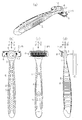
- FIG. 1 is a perspective view which shows a neutral state in the swing type razor concerning 1st Embodiment
- (b) is a rear view
- (c) is a front view
- (d) is also a side view
- FIG. (A) is the elements on larger scale of FIG.1 (b) which shows a neutral state in the swing type razor concerning 1st Embodiment
- (b) is the elements on larger scale of FIG.1 (d)
- Is a partial cross-sectional view of FIG. (A) is a perspective view which shows a neutral state in the swing type razor concerning 2nd Embodiment
- (b) is a rear view similarly
- (c) is a front view similarly
- (d) is also a side view FIG.
- FIG. (A) is the elements on larger scale of FIG.3 (b) which shows a neutral state in the swing type razor concerning 2nd Embodiment
- (b) is the elements on larger scale of FIG.3 (d)
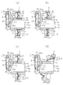
- (c) ) Is a partial cross-sectional view of FIG. (A) is a partial sectional view showing a neutral state in the swing-type razor according to the third embodiment
- (b) is a partial sectional view showing a neutral state in the swing-type razor according to the fourth embodiment
- (C) is a fragmentary sectional view which shows a neutral state in the swing-type razor concerning 5th Embodiment
- (d) is a fragmentary sectional view which shows the neutral state in the swing-type razor concerning 6th Embodiment.
- (A) is a partial sectional view showing a neutral state in the swing-type razor according to the seventh embodiment
- (b) is a partial sectional view showing a neutral state in the swing-type razor according to the eighth embodiment
- (C) is a fragmentary sectional view which shows a neutral state in the swing type razor concerning 9th Embodiment.
- (A) is a perspective view which shows a neutral state in the swing type razor concerning 10th Embodiment
- (b) is a rear view
- (c) is a front view
- (d) is also a side view FIG.
- FIG.7 (b) which shows a neutral state in the swing type razor concerning 10th Embodiment
- (b) is the elements on larger scale of FIG.7 (d)
- (c) ) Is also a partial plan view.
- (A) is a partial side view which shows the state which attached the cap to the razor head of the neutral position in the swing type razor concerning 10th Embodiment
- (b) is a partial top view similarly.
- FIG.8 (b) which shows the neutral state of the swing-type razor concerning 10th Embodiment
- (b) is the fragmentary sectional view of FIG.8 (c)
- (A) is a partial side view which shows the state which moved so that it might incline upwards in the swing type razor concerning 10th Embodiment
- (b) is also a partial rear view
- (c) is the same It is the fragmentary sectional view seen from the side.
- (A) is a partial side view which shows the state which moved so that it might incline downward in the swing type razor concerning 10th Embodiment, (b) is also a partial rear view, (c) is the same It is the fragmentary sectional view seen from the side.
- (A) is a partial side view which shows the back pressed state in the swing type razor concerning 10th Embodiment, (b) is a partial rear view, (c) is also the part seen from the side It is sectional drawing.
- (A) is the partial top view which shows the state which moved so that it might incline toward the left-right direction in the swing type razor concerning 10th Embodiment, (b) is a partial rear view, (c) is It is a partial plane sectional view similarly.
- the holder 1 shown in FIG. 1 has a grip portion 2 that is elongated along the vertical direction Z and a head portion 3 that is provided at the upper end of the grip portion 2.
- the grip portion 2 includes a main body portion 4 formed of a hard resin and at least one finger holder portion 5 formed of a soft resin and exposed to the outside of the main body portion 4.
- the head 3 has a support portion 6 that is formed integrally with the main portion 4 of the grip portion 2 from a hard resin that is the same material as the main portion 4.
- the support portion 6 is formed with an annular portion 6a extending in an annular shape.
- a razor head 7 shown in FIGS. 1 and 2A and 2B includes a blade assembly portion 8 to which a blade body 9 is assembled, and a support portion 6 of the head 3 of the holder 1 from the blade assembly portion 8. And a column-shaped supported portion 10 extending toward the surface.
- the annular portion 6 a of the support portion 6 defines a support hole 11 on the inside, and in the support hole 11, the inner periphery of the annular portion 6 a and the supported portion 10 of the razor head 7.
- An elastic plate 12 (elastic portion) is interposed between the outer periphery of the two.
- the outer periphery of the annular portion 6 a of the support portion 6 protrudes upward in the vertical direction Z from the blade assembly portion 8 of the razor head 7.
- the supported portion 10 includes a second connecting portion 13 having a cylindrical portion 14 (extension portion) and a bottom portion 15, and a first arm portion 17 and a second arm that protrude from the blade base 8 a of the blade assembly portion 8, respectively. And a first connecting portion 16 having a portion 18.
- the first arm part 17 and the second arm part 18 are inserted inside the cylinder part 14 and are only in the direction of the axis 13a so as not to rotate around the axis 13a along the extending direction of the cylinder part 14. It is guided along.
- the first arm portion 17 is in contact with the inside of the bottom portion 15 and restricts the movement of the first connecting portion 16 in the front-rear direction X.
- a locking collar portion 18 a (a coupling portion) is formed at the distal end portion of the second arm portion 18.
- the cylindrical portion 14 is formed with a locking hole 14a (a coupling portion).
- the locking collar portion 18a is engaged with the locking hole 14a to prevent undesired detachment of the first connecting portion 16 from the second connecting portion 13. Therefore, the 2nd connection part 13 and the 1st connection part 16 cannot mutually be removed.
- the cylindrical portion 14 and the bottom portion 15 of the second connecting portion 13 and the first arm portion 17 and the second arm portion 18 of the first connecting portion 16 are formed of hard resin.
- the elastic plate 12 is provided with a support portion 6 of the head 3 and a second connecting portion 13 of the supported portion 10 of the razor head 7 in a mold, and a rubber material or other soft material in a cavity in the mold. To be molded.
- the elastic plate 12 has an annular elastic portion 12 a that extends in an annular shape along the inner periphery of the annular portion 6 a of the support portion 6 and the outer periphery of the cylindrical portion 14 of the second connecting portion 13 in the support hole 11. .
- the outer peripheral portion of the annular elastic portion 12a is in surface contact with the inner peripheral portion of the annular portion 6a of the support portion 6, and is attached by heat and pressure during molding.
- the supported portion 10 penetrates the annular elastic portion 12a along the thickness direction (front-rear direction X) of the annular elastic portion 12a and is supported by the annular elastic portion 12a.
- the inner peripheral portion of the annular elastic portion 12a is in surface contact with the outer peripheral portion of the cylindrical portion 14 of the supported portion 10 and is attached by heat and pressure during molding.
- a bending allowance portion 19 is formed in the annular elastic portion 12a.
- the bending allowance portion 19 includes a ridge portion 20 that continuously extends in an annular shape around the tube portion 14 concentrically with the tube portion 14, and protrudes along the axis 13 a in a direction away from the blade assembly portion 8. And a groove portion 21 formed on the back surface of the strip portion 20.
- the protruding portion 20 may protrude along the axis 13 a in a direction approaching the blade assembly portion 8.
- the elastic plate 12 including the annular elastic portion 12a has a substantially uniform thickness (0.1 to 3 mm). In the annular elastic portion 12 a of the elastic plate 12, the bending allowance portion 19 may be made thinner than portions other than the bending allowance portion 19 to facilitate bending. In the bending allowance portion 19, the protruding dimension of the ridge portion 20 is 0.3 to 5 mm.
- the razor head 7 is held by the elastic plate 12 at a neutral position P shown in FIGS.
- the elastic plate 12 can be bent toward various moving positions.
- the elastic plate 12 has a direction of the axis 13a of the cylindrical portion 14 of the supported portion 10, a direction of rotation about the axis along the left-right direction Y, a direction of rotation about the axis along the vertical direction Z, It can bend in the direction X, the left-right direction Y, the up-down direction Z, or a combination thereof. Therefore, the razor head 7 can be moved from the neutral position P to the moving position in the three-dimensional direction against the elastic force.
- 3 to 4 show a second embodiment.
- 3 (a), (b), (c), and (d) correspond to FIGS. 1 (a), (b), (c), and (d) of the first embodiment, and FIGS. 4 (a), (b), and (c).
- FIGS. 2A, 2B and 2C of the first embodiment corresponds to FIGS. 2A, 2B and 2C of the first embodiment.
- the second embodiment differs from the first embodiment particularly in the following points.
- the supported portion 10 of the razor head 7 of the second embodiment has a first connecting portion 16 that is different from the first embodiment.
- the first connecting portion 16 is inserted inside the cylindrical portion 14 of the second connecting portion 13, and the direction of the axis 13 a is prevented from rotating around the axis 13 a along the extending direction of the cylindrical portion 14. Only guided along.
- the heat welding part 16a (joint part) of the first connecting part 16 is heat welded to the inside of the bottom part 15 by internal frictional heat generated by ultrasonic vibration. Therefore, the 1st connection part 16 and the 2nd connection part 13 become mutually non-removable by the heat welding part 16a.
- the cylindrical portion 14 and the bottom portion 15 of the second connecting portion 13 of the supported portion 10 of the razor head 7 are separately formed and fitted to each other.
- the bottom portion 15 has a larger diameter than the cylindrical portion 14.
- the outer peripheral portion of the bottom portion 15 protrudes radially outward from the cylindrical portion 14 and faces the annular elastic portion 12a of the elastic plate 12.
- FIG. 5A shows the third embodiment
- FIG. 5B shows the fourth embodiment
- FIG. 5C shows the fifth embodiment
- FIG. 5D shows the sixth embodiment. Show.
- FIGS. 5A to 5D correspond to FIG. 2C of the first embodiment, respectively.
- the third to sixth embodiments differ from the first embodiment particularly in the following points.
- the razor head 7 includes a blade assembly part 8 and a supported part 10 which are separated from each other.
- the blade base 22 of the blade assembly portion 8 includes an upper frame portion 22a, a lower frame portion 22b, and a strip plate portion 23 extending in an arch shape so as to connect the upper frame portion 22a and the lower frame portion 22b. It has.
- the supported portion 10 has a cylindrical shape, and the front end and the rear end are open. Cutouts 24 (joining portions) are formed in the upper portions of the outer peripheral edge portions of the front end and the rear end of the supported portion 10.
- a pair of upper protrusions 25 and a pair of lower protrusions 26 extending along the front-rear direction are formed below the notches 24 on the left and right sides of each outer peripheral edge.
- the band plate portion 23 of the blade base 22 is engaged with the notch 24 at the front end of the supported portion 10.
- the lower frame portion 22b (coupling portion) of the blade base 22 is engaged between the upper projection 25 and the lower projection 26 (coupling portion).
- the lower frame portion 22b of the blade base 22 is thermally welded to the supported portion 10 by internal frictional heat generated by ultrasonic vibration. Therefore, the supported portion 10 and the blade base 22 cannot be removed from each other.
- the supported portion 10 and the blade base 22 may be thermally welded so that they cannot be detached from each other. In that case, the protruding portion 20 protrudes in a direction approaching the blade assembly portion 8.
- a notch 27 is formed in the inner peripheral portion of the annular portion 6a of the support portion 6, and the annular elastic portion 12a of the elastic plate 12 is formed. Is molded so that the outer peripheral portion thereof is embedded in the notch 27. Further, a notch 28 is formed in the outer peripheral portion of the supported portion 10, and the inner peripheral portion of the annular elastic portion 12 a is formed to be embedded in the notch 28. As shown in FIGS. 5A and 5B, each of the outer peripheral portion and the inner peripheral portion of the elastic plate 12 of the third and fourth embodiments includes a biting portion 29 embedded in the notch 27, and a biting portion 29.
- each of the outer peripheral portion and the inner peripheral portion of the elastic plate 12 according to the fifth embodiment includes only a biting portion 29 embedded in the notch 27.
- the outer peripheral portion of the annular elastic portion 12 a is attached so as to be in surface contact with the inner peripheral portion of the annular portion 6 a of the support portion 6. Yes.
- the inner peripheral portion of the annular elastic portion 12 a is attached so as to be in surface contact with the outer peripheral portion of the supported portion 10.
- the elastic plates 12 of the third to fifth embodiments are line symmetric with respect to the axis 10 a of the supported portion 10. That is, the plane including the outer peripheral portion of the annular elastic portion 12a of the elastic plate 12 of the third to fifth embodiments and the plane including the inner peripheral portion of the annular elastic portion 12a are orthogonal to the axis 10a.
- the elastic plate 12 is formed asymmetrically with respect to the axis 10a.
- FIG. 6A shows the seventh embodiment
- FIG. 6B shows the eighth embodiment
- FIG. 6C shows the ninth embodiment.
- FIGS. 6A to 6C correspond to FIG. 2C of the first embodiment, respectively.
- the seventh to ninth embodiments differ from the first embodiment particularly in the following points.
- the support portion 6 and the second connecting portion 13 of the seventh embodiment are each formed from two parts.
- the elastic plate 12 is formed separately from the support portion 6 and the second connecting portion 13, and the elastic plate 12 is formed between two parts of the support portion 6 and two parts of the second connecting portion 13. Is sandwiched between.
- the 1st connection part 16 is provided with the latching arm 31 inserted in the 2nd coupling part 13, and the latching arm 31 has the latching recessed part 31a which acts as a coupling
- the second connecting portion 13 includes an operating button 32 that acts as an operating portion, and an operating spring 33 is fitted between the operating button 32 and the locking arm 31 of the first connecting portion 16.
- a locking arm 34 is attached to the operation button 32 in a cantilever shape, and the locking arm 34 has a locking projection 34a that acts as a coupling portion at its free end.
- the locking projection 34a of the locking arm 34 is engaged with the locking recess 31a of the locking arm 31 to prevent the second connecting portion 13 and the first connecting portion 16 from being detached.
- the second connecting portion 13 includes a concave portion 36 at a position facing the locking concave portion 31 a, and the concave portion 36 is engaged with the locking convex portion 34 a of the locking arm 34 with respect to the locking concave portion 31 a of the first connecting portion 16.
- a slope 36a for guiding the locking arm 34 so as to release the stop is provided.
- the supported portion 10 of the razor head 7 of the eighth embodiment includes a first connecting portion 16 and a second connecting portion 13 similar to those of the second embodiment.
- the first connecting portion 16 is inserted inside the cylindrical portion 14 of the second connecting portion 13, and the bottom portion 15 of the second connecting portion 13 is more than the cylindrical portion 14. Also has a large diameter.
- Magnets 35 are embedded in positions where the bottom 15 of the second connecting portion 13 and the first connecting portion 16 face each other, and the two magnets 35 are configured to be attracted to each other.
- the first connecting portion 16 is inserted inside the cylindrical portion 14 and is guided only along the direction of the axis 13a so as not to rotate around the axis 13a along the extending direction of the cylindrical portion 14. Yes.
- the blade assembly part 8 of the razor head 7 When the blade assembly part 8 of the razor head 7 is pulled against the magnetic force of the magnet 35 (coupling part), the blade assembly part 8 moves the first connecting part 16 along the direction of the axis 13a. It can be separated from the second connecting portion 13.
- the first connecting portion 16 When the first connecting portion 16 is inserted into the second connecting portion 13, the first connecting portion 16 is guided along the direction of the axis 13 a and is attracted to the second connecting portion 13 by the magnetic force of the magnet 35. Can. Therefore, the 1st connection part 16 and the 2nd connection part 13 can mutually be attached or detached.
- the elastic plate 12 of the eighth embodiment is the same as the elastic plate of the second embodiment.
- the cap is pulled together with the blade assembly portion 8, and the first connection portion 16 and the second connection portion 13 are pulled. Can be separated.
- the replaceable blade case is pulled together with the blade assembly part 8 to separate the first connecting part 16 and the second connecting part 13. can do.
- the ninth embodiment has a second connecting portion 13 different from the eighth embodiment.
- the bottom portion 15 can slide along a direction orthogonal to the extending direction of the cylindrical portion 14, and a first magnet and a second magnet 35 having different polarities are embedded in the bottom portion 15 along the sliding direction of the bottom portion 15.
- the bottom portion 15 is biased toward a bottom neutral position along the sliding direction of the bottom portion 15 by a spring (not shown).
- the first magnet 35 of the bottom 15 is disposed at a position facing the magnet 35 of the first connecting portion 16 and is configured to be attracted to the magnet 35 of the first connecting portion 16. Yes. Therefore, in the bottom neutral position, the first connecting portion 16 can be adsorbed to the second connecting portion 13 as in the eighth embodiment.
- the second magnet 35 is moved to a position facing the magnet 35 of the first connecting portion 16.
- the first connecting portion 16 and the second connecting portion 13 can be separated by the repulsive force between the second magnet 35 and the magnet 35 of the first connecting portion 16.
- the finger is separated from the bottom portion 15, the bottom portion 15 returns to the bottom neutral position by the elastic force of the spring. Therefore, the 1st connection part 16 and the 2nd connection part 13 can mutually be attached or detached.
- the spring 15 may be omitted, and the bottom 15 may be slid against the tube portion 14 against the frictional resistance between the tube portion 14 and the bottom portion 15.
- the attractive magnetic force may be generated between the magnet 35 and a magnetic material such as iron.
- the holder 1 shown in FIG. 7 has a grip portion 2 that is elongated along the vertical direction Z, and a head portion 3 provided at the upper end of the grip portion 2.
- the grip portion 2 includes a main portion 4 formed of a hard resin, and at least one finger rest portion 5 formed of a soft resin, a rubber material, or a soft material other than a rubber material and exposed to the outside of the main portion 4.
- the head 3 has a support portion 6 that is formed integrally with the main portion 4 of the grip portion 2 from a hard resin that is the same material as the main portion 4.
- the 7 and 8 and 10 (a) and 10 (b) includes an annular portion 6a formed in an approximately square annular shape by an upper side portion, a lower side portion, a left side portion, and a right side portion.
- the upper side portion, the lower side portion, the left side portion, and the right side portion are gently swollen so as to protrude outward from the annular portion 6a.
- the corner between the upper side and the left side, the corner between the upper side and the right side, the corner between the lower side and the left side, and the corner between the lower side and the right side are: It is a gentle curve and is smoothly connected to the upper side, the lower side, the left side, and the right side.
- the maximum distance along the left-right direction Y between the left side and the right side is set to about 27.5 mm
- the maximum distance along the up-down direction Z between the upper side and the lower side is about 21.0 mm. Is set to
- the razor head 7 shown in FIGS. 7 and 8 has a blade assembly part 8 assembled with a blade body 9 and a supported part 10 extending from the blade assembly part 8 toward the support part 6 of the head 3. is doing.
- the annular portion 6 a of the support portion 6 defines a support hole 11 on the inner side, and in the support hole 11, the inner periphery of the annular portion 6 a and the razor head 7 cover.
- An elastic plate 12 (elastic portion) is interposed between the outer periphery of the support portion 10.
- the upper part of the outer peripheral part of the annular part 6 a of the support part 6 projects upward in the vertical direction Z from the blade assembly part 8 of the razor head 7.
- the supported portion 10 of the razor head 7 includes a second connecting portion 13 having a cylindrical portion 14 (extending portion) and a bottom portion 15 (end portion), and a first protruding from the blade base 8a of the blade assembly portion 8.
- Connecting portion 16 The cylindrical portion 14 of the second connecting portion 13 has a rectangular cylindrical shape, and includes an upper wall portion, a lower wall portion, a left wall portion, and a right wall portion.
- the 1st connection part 16 is a bottomed square cylinder shape, and consists of an upper wall part, a lower wall part, a left wall part, a right wall part, and a bottom part (end part).
- the bottom 15 of the second connecting portion 13 has an opening 15a, and a connecting hole 37 that opens forward and rearward is formed in the second connecting portion 13.
- connection hole 37 a left guide ridge and a right guide ridge 38 extending along the front-rear direction X from the opening 15 a of the bottom portion 15 toward the blade assembly portion 8 are formed inside the upper wall portion of the cylindrical portion 14. Is formed.
- a positioning groove 39 is formed between the left guide ridge and the right guide ridge 38.
- a cantilever-like left side locking arm part 40 and a right side locking arm part 40 extending in the front-rear direction X from the opening 15 a toward the blade assembly part 8 are formed on the bottom part 15.
- a left side locking hole and a right side locking hole 41 (a locking recess, a coupling part) are formed in the left wall part and the right wall part of the first connecting part 16.
- a positioning ridge 42 extending along the front-rear direction X is formed on the outer side of the upper wall portion of the first connecting portion 16.
- the length along the left-right direction Y outside the upper wall portion and the lower wall portion of the cylindrical portion 14 of the second connecting portion 13 is set to about 17.0 mm, and the left of the cylindrical portion 14 of the second connecting portion 13 is left.
- the length along the vertical direction Z outside the wall portion and the right wall portion is set to about 10.5 mm.
- the first connecting part 16 is inserted into the connecting hole 37 of the second connecting part 13.
- the positioning protrusion 42 (coupling portion) of the first coupling portion 16 is inserted into the positioning groove 39 (coupling portion) of the second coupling portion 13.
- the first connecting portion 16 is guided only along the direction of the axis 13 a so as not to rotate around the axis 13 a along the extending direction of the cylindrical portion 14, and the connecting hole 37 of the second connecting portion 13. Inserted into (joining part).
- the bottom part of the first connecting part 16 abuts on the bottom part 15 of the second connecting part 13, and the rearward movement of the first connecting part 16 along the front-rear direction X is restricted.
- the bottom portion of the first connecting portion 16 is exposed through the opening 15 a of the bottom portion 15 and is substantially flush with the bottom portion 15.
- Each of the left side locking arm portion and the right side locking arm portion 40 (coupling portion) of the second connecting portion 13 includes a locking collar portion 40a (locking convex portion) at the lower end.
- the left side locking arm part and the right side locking arm part 40 of the second connecting part 13 are inserted into the left side locking hole and the right side locking hole 41 of the first connecting part 16, respectively, and each locking collar part 40a is This acts to prevent inadvertent detachment of the first connecting portion 16 from the second connecting portion 13. For this reason, the first connecting part 16 and the second connecting part 13 cannot be detached from each other.
- the cylinder part 14 and the bottom part 15 of the 2nd connection part 13, and the left side locking arm part and the right side locking arm part 40 of the 2nd connection part 13 are shape
- the elastic plate 12 is provided with the support portion 6 of the head 3 and the second connecting portion 13 of the supported portion 10 of the razor head 7 in the mold, and the same material as the finger holder 5 in the cavity in the mold. (Soft resin, rubber material, or soft material other than rubber material) is supplied and molded.
- the elastic plate 12 has an annular elastic portion 12 a that extends annularly along the inner periphery of the annular portion 6 a of the support portion 6 and the outer periphery of the cylindrical portion 14 of the second connecting portion 13 in the support hole 11.
- the holder 2 of the holder 1 has at least one main body 4 formed integrally with the support section 6 of the head 3 and at least one formed integrally with the elastic plate 12 of the head 3 and exposed to the outside of the main body 4.
- the finger holder 5 has irregularities of various shapes formed for at least one of providing a non-slip function and improving the feel.
- the elastic plate 12 and the finger holder 5 are made of a styrenic thermoplastic elastomer and have a Shore A hardness in the range of 20 to 60.
- the finger holder 5 is exposed asymmetrically on the back surface of the grip portion 2 adjacent to the head 3, and therefore the back surface of the grip portion 2 is different on the left side and the right side. It is configured.
- the main body 4 has a groove 4b on each of the left and right sides, the left groove 4b extends continuously, and the right groove 4b is divided in the middle.
- the finger holding part 5a made of elastomer is arranged in the divided part of the right groove part 4b, when the finger touches this part, the belly of the finger comes into surface contact with the finger holding part 5a.
- the finger holder 5a acts as a slip stopper. Further, the left side of the main body 4 having the continuously extending groove 4b is slippery.
- two through holes 4 a that can be used as hooking holes for hooking the hanging hooks are formed in the upper and lower parts of the main body 4. A part of the soft resin finger rest 5 is exposed in the upper through-hole 4a.
- the blade assembly part 8 is inserted into the supported part 10 as described above.
- the outer peripheral portion of the annular elastic portion 12a is in surface contact with the inner peripheral portion of the annular portion 6a of the support portion 6, and is attached by heat and pressure during molding.
- the supported portion 10 penetrates the annular elastic portion 12a along the thickness direction (front-rear direction X) of the annular elastic portion 12a and is supported by the annular elastic portion 12a.
- the inner peripheral portion of the annular elastic portion 12a is in surface contact with the outer peripheral portion of the cylindrical portion 14 of the supported portion 10 and is attached by heat and pressure during molding.
- a bending allowance portion 19 is formed in the annular elastic portion 12a.
- the bending allowance portion 19 includes a ridge portion 20 that extends continuously and annularly concentrically with the tube portion 14 outside the tube portion 14, and protrudes along the axis 13 a in a direction away from the blade assembly portion 8. And a groove portion 21 formed on the back surface of the strip portion 20.
- the inner region S is provided between the annular portion 6a of the support portion 6 and the supported portion 10 of the razor head 7, between the plane including the front inner peripheral edge and the plane including the rear inner peripheral edge of the annular portion 6a.
- the inner region S is provided between the plane including the front inner peripheral edge and the plane including the rear inner peripheral edge of the annular portion 6a.
- the elastic plate 12 is disposed in the inner region S.
- the bottom 15 of the second connecting portion 13 and the bottom of the first connecting portion 16 of the supported portion 10 of the razor head 7 are disposed in the inner region S of the support hole 11 behind the elastic plate 12.
- the protrusion 20 protrudes along the axis 13 a in a direction away from the blade assembly 8, but may protrude along the axis 13 a in a direction approaching the blade assembly 8.
- the elastic plate 12 including the annular elastic portion 12a has a substantially uniform thickness (0.1 to 3 mm).
- the bending allowance portion 19 may be made thinner than portions other than the bending allowance portion 19 to facilitate bending.
- the protruding dimension of the ridge portion 20 is 0.3 to 5 mm.
- the elastic plate 12 includes a left bending allowance portion 19 and a right bending allowance portion 43 that face each other in the left-right direction Y, and an upper deflection allowance portion and a lower deflection allowance portion 44 that face each other in the vertical direction Z.
- the inner peripheral shape of the annular portion 6 a of the support portion 6 and the outer peripheral shape of the second connecting portion 13 of the supported portion 10 are substantially similar.
- the interval between the left side portion and the left wall portion of the second connecting portion 13 and the interval between the right side portion of the support portion 6 and the right wall portion of the second connecting portion 13 are set substantially equal to each other.
- the protrusion 20 and the groove 21 of each of the bending allowances 43, 44, 45 are substantially in the middle between the side of the support 6 and the wall of the second connecting part 13, and the side of the support 6.
- the two connecting portions 13 are disposed adjacent to each other along the wall portion.
- the width along the left-right direction Y and the up-down direction Z of the elastic plate 12 between the support part 6 and the supported part 10 is set to about 5.0 mm.
- Deformation degrees (elasticity) indicating the difficulty of deformation of the bending allowance portions 43, 44, 45 of the elastic plate 12 are different from each other.
- the corner bend allowance 45 is shorter than the left bend allowance 43, the right bend allowance 43, the upper bend allowance 44, and the lower bend allowance 44.
- the corner deflection allowance portion 45 is curved so as to act as a fulcrum of the deflection allowance portions 43 and 44 at the four corners between the deflection allowance portions 43 and 44. Therefore, the degree of difficult deformation of the corner bending allowance portion 45 is higher than the degree of difficulty deformation of the left and right bending allowance portions 43 and the degree of difficulty deformation of the upper and lower bending allowance portions 44.
- the corner bending allowance portion 45 is not easily deformed by the left and right bend allowance portions 43 and the upper and lower bend allowance portions 44. Moreover, since the left side bending
- the razor head 7 is held at the neutral position P shown in FIGS. 8A, 8B, and 10C by the elastic plate 12 when not in use.
- the angle ⁇ of the skin contact surface of the razor head 7 with respect to the extending direction of the holder 1 is set to about 10 degrees.
- the bottom 15 of the second connecting portion 13 and the bottom of the first connecting portion 16 of the supported portion 10 of the razor head 7 are located behind the elastic plate 12 in the inner region S of the support hole 11. Is placed inside.
- the plate 12 is pressed.
- the elastic plate 12 can be bent toward various moving positions.
- the elastic plate 12 has a direction of the axis 13a of the cylindrical portion 14 of the supported portion 10, a direction of rotation about the axis along the left-right direction Y, a direction of rotation about the axis along the vertical direction Z, It can bend in the direction X, the left-right direction Y, the up-down direction Z, or a combination thereof. Therefore, the razor head 7 can be moved from the neutral position P to the moving position in the three-dimensional direction against the elastic force.
- the razor head 7 moves so as to tilt upward as shown in FIG. 11 and when the razor head 7 moves so as to tilt downward as shown in FIG.
- the upper deflection allowing portion and the lower deflection allowing portion 44 are deformed together.
- the upper and lower bending allowance portions 44 and the left and right bending allowance portions 43 are mainly deformed.
- the razor head 7 moves so as to incline toward the right as shown in FIG. 14 or when the razor head 7 moves so as to incline toward the left (not shown).
- the left side bending allowance part and the right side bending allowance part 43 are mainly deformed together.
- the corner bending allowance portion 45 is less likely to be deformed than the upper and lower bending allowance portions 44 and the left and right bending allowance portions 43.
- the shape of the bending allowance portions 43, 44, and 45 changes to a shape that hardly deforms as the deformation of the bending allowance portions 43, 44, and 45 progresses. Therefore, the degree of difficult deformation at the movement position of the bending allowance portions 43, 44, 45 is higher than the degree of difficulty deformation at the neutral position P of the bending allowance portions 43, 44, 45.
- the degree of difficulty of deformation of the bending allowance portions 43, 44, 45 increases as the razor head 7 moves from the neutral position P toward the movement position.
- the razor head 7 can move so as to incline upward from the neutral position P at a maximum of about 30 degrees (about 40 degrees with respect to the extending direction of the holder 1).
- the razor head 7 can move downward from the neutral position P so as to be inclined at a maximum of about 30 degrees.
- the razor head 7 can move from the neutral position P so as to be inclined at a maximum of about 25 degrees in the left-right direction.
- the razor head 7 can move backward from the neutral position P by 0.1 to 5.0 mm, preferably 0.1 to 2.0 mm.
- swinging of the razor head 7 can be suppressed in accordance with the user's intention by pressing at least one of the supported portion 10 and the elastic plate 12 from behind with a finger.
- the razor head 7 can move within the range of the gap between the cap 46 and the support portion 6 of the head 3.
- the movement range of the razor head 7 covered with the cap 46 is smaller than the movement range of the razor head 7 not covered with the cap 46.
- the cap 46 can be put on the razor head 7 from above.
- the bottom portion of 16 protrudes rearward from the bottom portion 15 of the second connecting portion 13.
- the bottom of the first connecting part 16 acts as the operation part 16b.
- the form of the locking collar part 40a of each of the left locking arm part and the right locking arm part 40 of the second connecting part 13 is different from the locking collar part of the tenth embodiment.
- the locking hook 40a is configured to release the locking of the locking hook 40a with respect to the locking hole 41 by pressing the operation portion 16b.
- the first connecting part 16 can be detached from the second connecting part 13 by pressing the operation part 16b. It is preferable that the resistance at the time of releasing the locking of the locking collar portion 40a with respect to the locking hole 41 is set appropriately so as not to damage the elastic plate 12.
- a magnet may be used to lock the first connecting portion 16 and the second connecting portion 13 as in the eighth and ninth embodiments. .
- the present invention has the following effects.
- the razor head 7 is supported only by the elastic plate 12 interposed between the support portion 6 of the head 3 of the holder 1 and the supported portion 10 of the razor head 7. Therefore, the support structure for supporting the razor head 7 can be simplified so that the razor head 7 can move from the neutral position P against the elastic force of the elastic plate 12.
- the outer peripheral portion of the annular elastic portion 12a of the elastic plate 12 is supported by the inner peripheral portion of the annular portion 6a of the support portion 6, and the supported portion of the razor head 7 by the inner peripheral portion of the annular elastic portion 12a of the elastic plate 12 10 is supported.
- the razor head 7 can be moved from the neutral position P to the moving position in the three-dimensional direction against the elastic force of the elastic plate 12 during use.
- the annular elastic portion 12a of the elastic plate 12 also acts as a cushion due to the elasticity of the annular elastic portion 12a, and the usability of the swing-type razor can be improved.
- the annular elastic portion 12a of the elastic plate 12 includes a bending allowance portion 19 having an annular ridge portion 20 and a groove portion 21. Therefore, the annular elastic portion 12a of the elastic plate 12 can be easily bent uniformly in the three-dimensional direction, and the cushioning property by the bending allowance portion 19 can be further improved. Further, since the annular ridge portion 20 of the bending allowance portion 19 protrudes in a direction along the axis 13a of the cylindrical portion 14, the annular elastic portion 12a is in a direction perpendicular to the axis 13a (the left-right direction Y or the up-down direction). It is easier to bend in the direction of the axis 13a (front-rear direction X) than Z). Further, since the elastic plate 12 acts in the same manner as a universal joint such as a ball joint, the annular elastic portion 12a is easily bent uniformly in the three-dimensional direction.
- the annular elastic portion 12 a of the elastic plate 12 includes a bending allowance portion 19 having an annular protrusion 20 and a groove 21.
- the bending allowance portion 19 is formed in a substantially quadrangular ring shape by left and right bending allowance portions 43, upper and lower bending allowance portions 44, and a corner bending allowance portion 45, and the elastic plate 12 includes a universal joint such as a ball joint and the like. It can act similarly.
- the difficulty deformation degree of the corner bending allowance portion 45 may be higher than the difficulty deformation degree of the left and right bending allowance portions 43 and the difficulty deformation degree of the upper and lower bending allowance portions 44.
- the left and right bending allowance portions 43, the upper and lower bending allowance portions 44, and the corner bending allowance portions 45 may have the same degree of difficult deformation.
- the bending allowance portion may be configured such that the degree of difficulty of deformation of the bending allowance portion increases.
- the shaving taste can be easily changed by adjusting the degree of difficult deformation of each bending allowance portion.
- the following embodiment may be configured as follows.
- the elastic plate 12 formed of a rubber material is used, but a foamed material, a viscous inclusion member, a coil spring, a leaf spring, or the like may be used.
- an annular shape or a quadrangular shape is used, but an annular shape such as a triangle or an ellipse may be used, and a U-shape or the like is partially cut away. There may be.
- a plurality of through holes may be arranged in a ring at equal intervals in the annular elastic portion 12a of the elastic plate 12.
- the elastic part may be a hemispherical shape that swells on the support part.
- the part corresponding to the elastic part may be made thinner to make it easier to bend.
- the thickness is changed, the shape of the protrusion 20 is changed, and the position where the supported portion 10 is supported with respect to the elastic plate 12 is defined.
- the degree of difficulty (elasticity) indicating the difficulty of deformation around the elastic plate 12 may be changed in the same manner.
- -One or a plurality of thin plate portions are provided between the support portion 6 of the head 3 and the supported portion 10 of the razor head 7, and the elastic plate 12 is rotated in the rotation direction about the axis 13a along the front-rear direction X.
- the thin plate portion does not prevent the annular elastic portion 12a of the elastic plate 12 from bending in a direction other than the rotation direction around the axis 13a along the front-rear direction X.
- the elastic portion may be a circular elastic plate 12 with an inner plate extending inside the annular elastic portion 12a. In this case, one side of the inner plate in the front-rear direction X is covered. The end portions of the support portion can be connected.
- the pair of locking arms that sandwich the strip plate portion 23 are cut out. 24 may be provided.
- the locking arm is configured such that the belt plate portion 23 does not come out between the pair of locking arms.
- the second The first connecting part 16 and the second connecting part 13 can be connected to each other while the first connecting part 16 is viewed from the outside of the connecting part 13 through the second connecting part 13.
- the elastic part may have a pump function, and liquid or gel-like shaving aid may be supplied from the elastic part to the razor head.
- the shaving aid may be supplied to the skin surface or the razor head in accordance with the swing at the time of use.
- the shaving head may be supplied to the razor head by moving the razor head by hand immediately before use.
- the locking arm of the cap 46 is locked to the support portion 6 of the head 3, and the razor head 7 may be regulated.
- a switching member that can be selectively engaged and disengaged is provided between the head 3 and the razor head 7 so that the razor head 7 can be switched between the swingable state and the swingable state. It may be.
- SYMBOLS 1 ... Holder, 2 ... Gripping part, 3 ... Head, 5 ... Finger holding part, 6 ... Support part, 6a ... Ring part of support part, 7 ... Razor head, 8 ... Blade assembly part, 9 ... Blade DESCRIPTION OF SYMBOLS 10 ... Supported part of razor head, 11 ... Support hole of support part, 12 ... Elastic plate (elastic part), 12a ... Ring elastic part of elastic plate, 13 ... Second connection part, 16 ... First connection Part, 19, 43, 44, 45 ... deflection allowable part, P ... neutral position.
Landscapes
- Life Sciences & Earth Sciences (AREA)
- Forests & Forestry (AREA)
- Engineering & Computer Science (AREA)
- Mechanical Engineering (AREA)
- Dry Shavers And Clippers (AREA)
Abstract
ホルダの頭部の支持部(6)と剃刀ヘッド(7)の被支持部(10)との間に弾性板(12)を介在させ、支持部(6)の環状部(6a)の内周部で弾性板(12)の環状弾性部(12a)の外周部を支持するとともに、弾性板(12)の環状弾性部(12a)の内周部に剃刀ヘッド(7)の被支持部(10)を挿着している。剃刀ヘッド(7)を中立位置(P)から弾性板(12)の弾性力に抗して移動可能に支持するための支持構造により、使用時に剃刀ヘッド(7)は、中立位置(P)から弾性板(12)の弾性力に抗して三次元方向の移動位置まで移動させられ得る。さらに、弾性板(12)は、剃刀ヘッド(7)の使用時にクッション機能を果たし、首振り式剃刀の使い勝手を良くすることができる。
Description
本発明は、刃体を組み付けた剃刀ヘッドがホルダの頭部に対し弾性力に抗して移動し得る首振り式剃刀に関するものである。
特許文献1には、従来の安全剃刀が開示されている。特許文献1の安全剃刀は、柄と、刃体を有する替刃ユニットと、柄及び替刃ユニットの間のジョイントとを備えている。ジョイントは、替刃ユニットを支持するための一対のジャーナル軸受と、替刃ユニットを替刃ユニットの中立位置へ向けて付勢する弾性片とを備えている。柄は、ジョイントを枢動可能に支持する枢動軸と、ジョイントをジョイントの中立位置へ向けて付勢する弾性部材とを備えている。替刃ユニットは、替刃ユニットの中立位置を基準として、ジャーナル軸受の周りを、弾性片による弾性力に抗して、揺動する。さらに、替刃ユニットを支持するジョイントは、ジョイントの中立位置を基準として、枢動軸の周りを、弾性部材による弾性力に抗して、替刃ユニットとともに揺動する。
特許文献1の安全剃刀では、ジャーナル軸受を中心とする揺動方向、および枢動軸を中心とする揺動方向のそれぞれに対して揺動支持構造を必要とするため、剃刀の構造が複雑になっていた。
この発明は、頭部を有するホルダと、刃体を有する剃刀ヘッドとを備える首振り式剃刀において、剃刀ヘッドをホルダの頭部に対する中立位置から弾性力に抗して移動させ得るように、剃刀ヘッドをホルダの頭部に支持するための支持構造を簡単にすることを目的としている。
本発明の一態様における首振り式剃刀は、頭部を有するホルダと、刃体を有する剃刀ヘッドとを備える。首振り式剃刀は、ホルダの頭部に設けられた支持部と、剃刀ヘッドに設けられた被支持部と、支持部および被支持部の間に設けられた弾性部とを備える。剃刀ヘッドは、弾性部により静止状態に保持される中立位置と、その中立位置から離間した移動位置との間において移動可能に配置される。前記剃刀ヘッドは、前記弾性部の付勢力に抗して中立位置から移動位置まで移動し、弾性部の付勢力によって移動位置から中立位置まで復帰する。この場合、剃刀ヘッドを弾性部により支持することができるので、剃刀ヘッドを中立位置から弾性力に抗して移動可能に支持する支持構造を簡単にすることができる。
前記弾性部は前記頭部の支持部に支持された外周部を有していることが好ましい。この場合、弾性部の外周部が頭部の支持部に支持されているので、弾性部において弾性部の外周部よりも内側を撓ませることができる。
前記弾性部は、弾性部の外周部よりも内側で剃刀ヘッドの被支持部を支持していることが好ましい。この場合、弾性部において撓み易くした外周部の内側で被支持部を支持するため、剃刀ヘッドを弾性力に抗して移動させ易くするとともに中立位置に復帰させ易い。
前記弾性部は弾性板であることが好ましい。この場合、弾性部が板状であるため、弾性板において弾性部の外周部の内側を撓ませ易い。
前記剃刀ヘッドの被支持部は、弾性板の厚み方向の両側面のうち少なくとも一方の側面に支持されていることが好ましい。この場合、剃刀ヘッドを弾性板の厚み方向へ弾性力に抗して移動させ易くするとともに中立位置に復帰させ易い。
前記頭部の支持部は環状に延びた環状部を有し、前記環状部は、内側に支持孔を画定し、前記弾性部は、支持孔内において、前記支持部の環状部の内周と前記剃刀ヘッドの被支持部の外周との間に、前記環状部の内周及び前記被支持部の外周に沿って環状に延びる環状弾性部を有していることが好ましい。頭部の支持部の環状部は、環状に連続して延びていても良く、また複数の支持部を環状に配設させてもよい。また、弾性部の環状弾性部は、環状に連続して延びていても良く、また複数の弾性部を環状に配設させてもよい。この場合、支持孔で弾性部の環状弾性部を撓ませることができる。
前記弾性部は変形のし難さを示す難変形度の異なる複数の撓み許容部を有している。この場合、剃刀ヘッドの首振り方向に応じて弾性部の難変形度を変えて剃り味を変更することができる。
前記弾性部の各撓み許容部は互いに隣接して並設されていることが好ましい。この場合、難変形度の異なる複数の撓み許容部を有する弾性部を容易に設けることができる。
前記弾性部の各撓み許容部は剃刀ヘッドの被支持部の周りにおいて環状をなすように並設されていることが好ましい。この場合、難変形度の異なる複数の撓み許容部を有する弾性部を容易に設けることができる。
相対向する撓み許容部は同じ難変形度を有していることが好ましい。この場合、剃刀ヘッドの同じ首振り方向において、同じ難変形度を有するように弾性部を設けることにより、良好な剃り味を得ることができる。
前記弾性部は剃刀ヘッドが中立位置から移動位置へ移動するに従って変形する撓み許容部を有し、移動位置における撓み許容部の難変形度は、中立位置における撓み許容部の難変形度より高くなっていることが好ましい。この場合、首振りの始めに剃り味を柔らかくするとともに、首振りの終わりに剃刀ヘッドを安定させて、剃り味を向上させることができる。
ホルダは頭部に一体に設けられた把持部を備え、この把持部は、頭部の弾性部と一体に成形され、かつ露出する指当部を有していることが好ましい。この場合、弾性部と指当部とを有するホルダを容易に成形することができる。
前記弾性部は20以上60以下の範囲のショアA硬度を有していることが好ましい。この場合、弾性部を適度な難変形度にして使用時の剃り味を向上させることができる。
前記弾性部は、剃刀ヘッドの中立位置において、支持孔内で、支持部の環状部と剃刀ヘッドの被支持部との間に配置されていることが好ましい。この場合、使用時に弾性部が不用意に触れられて剃刀ヘッドの首振りが妨げられることがなく、剃刀の使い勝手を良くすることができる。
前記剃刀ヘッドの被支持部は、刃体を組み付けた刃体組付部から延びる第一の連結部と、前記弾性部を前記頭部の支持部との間で介在させた第二の連結部と、第一の連結部および第二の連結部を互いに支持する結合部とを有し、第二の連結部において刃体組付部から離間する端部は、剃刀ヘッドの中立位置において、前記支持孔内に配置されていることが好ましい。この場合、使用時に剃刀ヘッドの被支持部の第二の連結部が不用意に触れられて、剃刀ヘッドの首振りが邪魔されることがなく、剃刀の使い勝手を良くすることができる。
前記頭部の支持部の環状部は環状に連続して延びていることが好ましい。この場合、支持部の連続して延びる環状部に弾性部の環状弾性部を支持して、支持孔で弾性部の環状弾性部を撓ませることができる。
前記弾性部の環状弾性部は環状に連続している。この場合、弾性部の連続した環状弾性部を支持部の環状部に支持して、支持孔で弾性部の環状弾性部を撓ませることができる。
前記剃刀ヘッドは様々な移動位置へ移動し得る。この場合、簡単な支持構造で、剃刀ヘッドを中立位置から弾性力に抗して様々な移動位置に移動させることができる。
前記剃刀ヘッドの被支持部は前記弾性部の環状弾性部の内周で延びる延設部を有し、この弾性部は延設部の延設方向に沿う軸線の方向、または該軸線に交差する方向へ移動して撓み得る。この場合、剃刀ヘッドを中立位置から弾性力に抗して三次元方向の移動位置に移動させることができる。
前記剃刀ヘッドの被支持部は前記弾性部の環状弾性部の内周で延びる延設部を有し、この弾性部は延設部の延設方向に沿う軸線の方向、または該軸線に交差する方向へ移動して撓み得る。この場合、剃刀ヘッドを中立位置から弾性力に抗して三次元方向の移動位置に移動させることができる。
前記弾性部は撓み許容部を有していることが好ましい。例えば、撓み許容部は、前記延設部の周りで環状に連続して延び、かつ軸線に沿って突出する突条部と、突条部の裏面に形成された溝部とを有している。この場合、弾性部の環状弾性部を撓み許容部により撓み易くすることができる。
前記弾性部は、前記頭部の支持部と剃刀ヘッドの被支持部と別々に設けられて、支持部及び被支持部に対し連結されていることが好ましい。この場合、弾性部と頭部の支持部と剃刀ヘッドの被支持部とは、成形し易い。
剃刀ヘッドの被支持部は、刃体を組み付けた刃体組付部から延びる第一の連結部と、前記弾性部を前記頭部の支持部との間で介在させた第二の連結部と、第一の連結部および第二の連結部を互いに支持する結合部とを有していることが好ましい。この場合、剃刀ヘッドの被支持部は成形し易い。
前記剃刀ヘッドの被支持部における第一の連結部および第二の連結部は、結合部で互いに取り外し不能に支持されていることが好ましい。この場合、剃刀ヘッドの被支持部は成形し易い。
前記剃刀ヘッドの被支持部における第一の連結部および第二の連結部は、結合部で着脱可能に支持されていることが好ましい。この場合、剃刀ヘッドにおいて刃体を組み付けた組付部を交換することができる。
第一の連結部に設けた係止凹部と第二の連結部に設けた係止凸部とが互いに着脱されることが好ましい。この場合、結合部の第一の連結部および第二の連結部を係止凹部と係止凸部とにより着脱することができる。
結合部において、第二の連結部と第一の連結部とが磁力により互いに取着されることが好ましい。この場合、第一の連結部および第二の連結部を結合部で、選択的に、磁力により互いに取着し、または磁力に抗して互いに離脱させることができる。
結合部において、第二の連結部と第一の連結部とを互いに着脱させる操作部を設けていることが好ましい。この場合、結合部で第一の連結部および第二の連結部を操作部により着脱させることができる。
前記弾性部は、前記頭部の支持部と剃刀ヘッドの被支持部とを金型内に設置し、金型内のキャビティに材料を供給して成形されていることが好ましい。この場合、弾性部は頭部の支持部及び剃刀ヘッドの被支持部に対し一体に取着されることができる。
剃刀ヘッドにおける刃体の刃先は左右方向に沿って延設している。前記弾性部の各撓み許容部は、左右方向で相対向する左側撓み許容部および右側撓み許容部と、左右方向に対し直交する上下方向で相対向する上側撓み許容部および下側撓み許容部と、左右の撓み許容部及び上下の撓み許容部の間の四隅部において、それぞれ対角方向で相対向する四つの隅部撓み許容部とを有することが好ましい。さらに、隅部撓み許容部の難変形度は、左右の撓み許容部の難変形度、および上下の撓み許容部の難変形度よりも高いことが好ましい。この場合、剃刀ヘッドが左右方向と上下方向とで首振りし易くして首振り動作を安定させることができる。
前記左側撓み許容部および右側撓み許容部は互いに同じ難変形度を有し、上側撓み許容部および下側撓み許容部は互いに同じ難変形度を有し、各隅部撓み許容部はそれぞれ同じ難変形度を有していることが好ましい。この場合、剃刀ヘッドの首振り方向に沿って対向する弾性部の部分の難変形度が等しくなり、良好な剃り味を得ることができる。
前記撓み許容部の難変形度は、剃刀ヘッドが中立位置から移動位置に移動するに従い高くなることが好ましい。この場合、首振りの始めに剃り味を柔らかくするとともに、首振りの終わりに剃刀ヘッドを安定させて、剃り味を向上させることができる。
前記剃刀ヘッドの被支持部は、刃体を組み付けた刃体組付部から延びる第一の連結部と、前記弾性部を前記頭部の支持部との間で介在させた第二の連結部と、第一の連結部および第二の連結部を互いに支持する結合部とを有していることが好ましい。また、結合部は、第一の連結部および第二の連結部が所定の位置関係にある場合にのみ、第一の連結部および第二の連結部を互いに支持し得る。この場合、剃刀ヘッドの被支持部の第一の連結部および第二連結部が結合可能である位置を限定して、ホルダに対する剃刀ヘッドの向きを一定にすることができる。
前記剃刀ヘッドの被支持部は、刃体を組み付けた刃体組付部から延びる第一の連結部と、前記弾性部を前記頭部の支持部との間で介在させた第二の連結部と、それらの連結部を互いに着脱可能に支持する結合部とを有することが好ましい。さらに、第一の連結部は、刃体組付部から離間した第一の連結部の部分において、第二の連結部から離間するように突出する操作部を有していることが好ましい。この場合、操作部により剃刀ヘッドをホルダに対し容易に着脱することができる。
前記把持部は頭部の支持部と一体に成形された主体部を有し、前記指当部は主体部から露出していることが好ましい。この場合、弾性部と指当部と主体部とを有するホルダが容易に成形されることができる。
第一の連結部において刃体組付部から離間した端部は、剃刀ヘッドの中立位置で、前記支持孔内に配置されていることが好ましい。この場合、使用時に剃刀ヘッドの被支持部の第一の連結部が不用意に触れられて、剃刀ヘッドの首振りが妨げられることがなく、剃刀の使い勝手を良くすることができる。
本発明は、首振り式剃刀において、刃体を組み付けた剃刀ヘッドをホルダの頭部に対する中立位置から弾性力に抗して移動させ得るように、剃刀ヘッドをホルダの頭部に支持する支持構造を簡単にすることができる。
まず、本発明の第1実施形態にかかる首振り式剃刀について不使用時の中立状態を基本として図1~2を参照して説明する。
図1に示すホルダ1は、上下方向Zに沿って細長く延設された把持部2と、把持部2の上端部に設けられた頭部3とを有している。把持部2は、硬質樹脂により成形された主体部4と、軟質樹脂により成形され、かつ主体部4の外側に露出する少なくとも1つの指当部5とを有している。頭部3は、主体部4と同一の材料である硬質樹脂により、把持部2の主体部4と一体に成形された支持部6を有している。なお、把持部2の主体部4および頭部3の支持部6の少なくとも一方を硬質樹脂以外の硬質材により形成してもよい。また、指当部5を軟質樹脂以外の軟質材により形成してもよい。
支持部6には円環状に延びる環状部6aが形成されている。図1及び図2(a)(b)に示す剃刀ヘッド7は、刃体9を組み付けた刃体組付部8と、刃体組付部8からホルダ1の頭部3の支持部6に向けて延びる円柱状の被支持部10とを有している。図2(c)に示すように、支持部6の環状部6aは、内側に支持孔11を画定し、支持孔11内において、環状部6aの内周と、剃刀ヘッド7の被支持部10の外周との間には、弾性板12(弾性部)が介在されている。支持部6の環状部6aの外周は上下方向Zで剃刀ヘッド7の刃体組付部8よりも上方へ突出している。
被支持部10は、筒部14(延設部)および底部15を有する第二の連結部13と、刃体組付部8の刃台8aからそれぞれ突出する第一腕部17および第二腕部18を有する第一の連結部16とからなる。第一腕部17および第二腕部18は、筒部14の内側に挿入されており、筒部14の延設方向に沿う軸線13aを中心に回動しないように、軸線13aの方向のみに沿って案内されている。第一腕部17は、底部15の内側に当接して、第一の連結部16の前後方向Xへの移動を規制している。第二腕部18の先端部には係止鉤部18a(結合部)が形成されている。筒部14には係止孔14a(結合部)が形成されている。係止鉤部18aは、係止孔14aに係入されて、第二の連結部13からの第一の連結部16の望ましくない離脱を防止している。そのため、第二の連結部13および第一の連結部16は互いに取り外し不能である。第二の連結部13の筒部14及び底部15、ならびに第一の連結部16の第一腕部17及び第二腕部18は、硬質樹脂により成形されている。
弾性板12は、頭部3の支持部6と剃刀ヘッド7における被支持部10の第二の連結部13とを金型内に設置し、金型内のキャビティにゴム材または他の軟質材を供給して成形される。弾性板12は、支持孔11内において支持部6の環状部6aの内周と第二の連結部13の筒部14の外周とに沿って円環状に延びる環状弾性部12aを有している。弾性板12の成形後に、前述したように刃体組付部8が被支持部10に挿着される。環状弾性部12aの外周部は支持部6の環状部6aの内周部に面接触して、成形時の熱および圧力により取着されている。被支持部10は、環状弾性部12aを、環状弾性部12aの厚み方向(前後方向X)に沿って貫通して、環状弾性部12aに支持されている。環状弾性部12aの内周部は被支持部10の筒部14の外周部に面接触して、成形時の熱および圧力により取着されている。環状弾性部12aには撓み許容部19が形成されている。撓み許容部19は、筒部14の周りにおいて筒部14と同心に環状に連続して延び、かつ刃体組付部8から離れる向きへ軸線13aに沿って突出する突条部20と、突条部20の裏面に形成された溝部21とを有している。突条部20は、刃体組付部8に接近する向きへ軸線13aに沿って突出していてもよい。環状弾性部12aを含む弾性板12は、略均一の厚み(0.1~3mm)を有している。弾性板12の環状弾性部12aにおいて撓み許容部19を撓み許容部19以外の部分より薄くして、撓み易くしてもよい。撓み許容部19において突条部20の突出寸法は0.3~5mmになっている。
剃刀ヘッド7は弾性板12により図2(b)(c)に示す中立位置Pで保持される。使用時に中立位置Pに位置する剃刀ヘッド7に力が与えられると、弾性板12は、様々な移動位置へ向かって撓み得る。例えば、弾性板12は、被支持部10の筒部14の軸線13aの方向、左右方向Yに沿う軸線を中心に回動する方向、上下方向Zに沿う軸線を中心に回動する方向、前後方向X、左右方向Y、上下方向Z、またはそれらを組み合わせた方向へ向かって撓み得る。従って、剃刀ヘッド7を中立位置Pから弾性力に抗して三次元方向の移動位置に移動させることができる。
図3~4は第2実施形態を示す。図3(a)(b)(c)(d)が第1実施形態の図1(a)(b)(c)(d)に対応するとともに、図4(a)(b)(c)が第1実施形態の図2(a)(b)(c)に対応する。第2実施形態は、特に下記の点で第1実施形態と異なる。
・ 第2実施形態の剃刀ヘッド7の被支持部10は、第1実施形態と異なる第一の連結部16を有する。第一の連結部16は、第二の連結部13の筒部14の内側に挿入されており、筒部14の延設方向に沿う軸線13aを中心に回動しないように、軸線13aの方向のみに沿って案内されている。第一の連結部16の熱溶着部16a(結合部)が、超音波振動で発生する内部摩擦熱により、底部15の内側に熱溶着されている。そのため、熱溶着部16aにより、第一の連結部16および第二の連結部13は互いに取り外し不能になる。
・ 第2実施形態において、弾性板12の環状弾性部12aの外周部が支持部6の環状部6a内に埋め込まれるように成形されているとともに、環状弾性部12aの内周部が第二の連結部13の筒部14の外周部に埋め込まれるように成形されている。
・ 第2実施形態において、剃刀ヘッド7の被支持部10の第二の連結部13の筒部14と底部15とが別々に形成されて互いに嵌着されている。底部15は筒部14よりも大きな直径を有している。底部15の外周部は筒部14から放射方向外向きに突出して、弾性板12の環状弾性部12aに面している。
図5(a)は第3実施形態を示し、図5(b)は第4実施形態を示し、図5(c)は第5実施形態を示し、図5(d)は第6実施形態を示している。図5(a)~(d)は、それぞれ、第1実施形態の図2(c)に対応している。第3~6実施形態は、特に下記の点で第1実施形態と異なる。
図5(a)~(d)に示すように、第3~6実施形態において、剃刀ヘッド7は互いに分離された刃体組付部8と被支持部10とを備える。刃体組付部8の刃台22は、上枠部22aと、下枠部22bと、上枠部22a及び下枠部22bの間を連結するように、アーチ状に延びる帯板部23とを備えている。被支持部10は、筒状をなし、前端および後端が開放されている。被支持部10の前端および後端の外周縁部の上部にはそれぞれ切欠き24(結合部)が形成されている。各外周縁部の左側および右側には、切欠き24より下方において、それぞれ前後方向に沿って延びる一対の上側の突起25および一対の下側の突起26が形成されている。図5(a)~(d)において、被支持部10の前端において、刃台22の帯板部23が切欠き24に係入されている。また、刃台22の下枠部22b(結合部)が上側の突起25および下側の突起26(結合部)の間に係入されている。刃台22の下枠部22bが、超音波振動で発生する内部摩擦熱により、被支持部10に熱溶着されている。そのため、被支持部10と刃台22とは互いに取り外し不能になる。被支持部10の後端において、同様にして、被支持部10と刃台22とが互いに取り外し不能に熱溶着されてもよい。その場合には、突条部20が刃体組付部8に接近する向きへ突出する。
図5(a)~(c)に示すように、第3~5実施形態においては、支持部6の環状部6aの内周部に切欠き27が形成され、弾性板12の環状弾性部12aの外周部が切欠き27内に埋め込まれるように成形されている。また、被支持部10の外周部に切欠き28が形成され、環状弾性部12aの内周部が切欠き28内に埋め込まれるように成形されている。図5(a)、(b)に示すように、第3、4実施形態の弾性板12の外周部及び内周部の各々は、切欠き27内に埋め込まれるくい込み部29と、くい込み部29から前後方向に沿って延びて、弾性板12の外周部及び内周部の対応する一方に面接触された延設部30とを備える。図5(c)に示すように、第5実施形態の弾性板12の外周部及び内周部の各々は、切欠き27内に埋め込まれるくい込み部29のみを備えている。
図5(d)に示すように、第6実施形態の弾性板12において、環状弾性部12aの外周部は、支持部6の環状部6aの内周部に面接触するように取着されている。環状弾性部12aの内周部は、被支持部10の外周部に面接触するように取着されている。第3~5実施形態の弾性板12は被支持部10の軸線10aに対して線対称である。すなわち、第3~5実施形態の弾性板12の環状弾性部12aの外周部を含む平面、および環状弾性部12aの内周部を含む平面は、軸線10aに対して直交する。それに対し、第6実施形態の弾性板12の環状弾性部12aの外周部を含む平面、および環状弾性部12aの内周部を含む平面は被支持部10の軸線10aに対し斜めに交差し、弾性板12は、軸線10aに対して非対称に形成されている。
図6(a)は第7実施形態を示し、図6(b)は第8実施形態を示し、図6(c)は第9実施形態を示す。図6(a)~(c)は、それぞれ、第1実施形態の図2(c)に対応する。第7~9実施形態は、特に下記の点で第1実施形態と異なる。
図6(a)に示すように、第7実施形態の支持部6及び第二の連結部13はそれぞれ二つの部品から形成される。弾性板12は、支持部6及び第二の連結部13とは別々に形成されており、弾性板12は、支持部6の二つの部品の間、および第二の連結部13の二つの部品の間に挟持されている。第一の連結部16は、第二の連結部13に挿入される係止腕31を備え、係止腕31は、結合部として作用する係止凹部31aを有する。第二の連結部13は、操作部として作用する操作ボタン32を備え、操作ボタン32と第一の連結部16の係止腕31との間に操作ばね33が嵌め込まれている。操作ボタン32には、係止腕34が片持ち梁状に取り付けられ、係止腕34はその自由端部に結合部として作用する係止凸部34aを有している。係止腕34の係止凸部34aが係止腕31の係止凹部31aに係入されて、第二の連結部13および第一の連結部16の離脱を防止している。第二の連結部13は、係止凹部31aに対向する位置に凹部36を備え、凹部36は、第一の連結部16の係止凹部31aに対する係止腕34の係止凸部34aの係止を解除するように係止腕34を案内する斜面36aを備えている。操作ボタン32を操作ばね33の弾性力に抗して押すと、凹部36の斜面36aに係止腕34の係止凸部34aが案内され、係止腕34が撓んで係止凹部31aと係止凸部34aとの係止が解除される。それにより、第一の連結部16の係止腕31が操作ボタン32の押圧力と操作ばね33の弾性力とにより第二の連結部13から離脱させられる。そのため、第7実施形態において、第二の連結部13および第一の連結部16は互いに着脱可能になる。
第8実施形態の剃刀ヘッド7の被支持部10は、第2実施形態と同様の第一の連結部16および第二の連結部13を備えている。図6(b)に示すように、第一の連結部16は第二の連結部13の筒部14の内側に挿入されているとともに、第二の連結部13の底部15が筒部14よりも大きな直径を有している。第二の連結部13の底部15と第一の連結部16との互いに対向する位置には、それぞれ磁石35が埋設されており、両磁石35は、互いに吸着するように構成されている。第一の連結部16は、筒部14の内側に挿入されており、筒部14の延設方向に沿う軸線13aを中心に回動しないように、軸線13aの方向のみに沿って案内されている。磁石35(結合部)の磁力に抗して剃刀ヘッド7の刃体組付部8を引くと、刃体組付部8は、第一の連結部16を、軸線13aの方向に沿って、第二の連結部13から分離することができる。第一の連結部16を第二の連結部13に挿入すると、第一の連結部16は、軸線13aの方向に沿って案内されて、磁石35の磁力により第二の連結部13に吸着されることができる。そのため、第一の連結部16および第二の連結部13は互いに着脱可能になる。そのほか、第8実施形態の弾性板12も第2実施形態の弾性板と同様である。剃刀ヘッド7において刃体組付部8にキャップ(図示せず)が被せてある場合にはそのキャップを刃体組付部8とともに引いて、第一の連結部16および第二の連結部13を分離することができる。刃体組付部8を替刃ケース(図示せず)に挿入する際にその替刃ケースを刃体組付部8とともに引いて、第一の連結部16および第二の連結部13を分離することができる。
図6(c)に示すように、第9実施形態は、第8実施形態と異なる第二の連結部13を有する。筒部14の延設方向に直交する方向に沿って底部15はスライドすることができ、底部15には底部15のスライド方向に沿って互いに異なる極性を示す第一磁石および第二磁石35が埋設されている。底部15は、ばね(図示せず)により底部15のスライド方向に沿って底部中立位置に向けて付勢されている。底部中立位置において、底部15の第一磁石35は、第一の連結部16の磁石35に対向する位置に配置されるとともに、第一の連結部16の磁石35に吸着するように構成されている。従って、底部中立位置では、第8実施形態と同様に第一の連結部16を第二の連結部13に吸着することができる。例えば手指により底部15を底部中立位置から筒部14に対しばねの弾性力に抗してスライドさせると、第二磁石35が第一の連結部16の磁石35に対向する位置に移動させられ、第二磁石35と第一の連結部16の磁石35との反発力により第一の連結部16および第二の連結部13を分離することができる。手指を底部15から離すと、ばねの弾性力により底部15が底部中立位置に戻る。そのため、第一の連結部16および第二の連結部13は互いに着脱可能になる。なお、このばねを省略して筒部14に対し底部15を筒部14及び底部15の間の摩擦抵抗に抗してスライドさせてもよい。
なお、吸着磁力は磁石35と鉄などの磁性体との間で生じるようにしてもよい。
次に、本発明の第10実施形態及びその別例にかかる首振り式剃刀について不使用時の中立状態を基本として図7~14を参照して説明する。
図7に示すホルダ1は、上下方向Zに沿って細長く延設された把持部2と、把持部2の上端部に設けられた頭部3とを有している。把持部2は、硬質樹脂により成形された主体部4と、軟質樹脂またはゴム材またはゴム材以外の軟質材により成形され、かつ主体部4の外側に露出する少なくとも1つの指当部5とを有している。頭部3は、主体部4と同一の材料である硬質樹脂により、把持部2の主体部4と一体に成形された支持部6を有している。
図7,8及び図10(a)(b)に示す支持部6は、上辺部と下辺部と左辺部と右辺部とにより略四角形の環状に形成される環状部6aを備えている。上辺部と下辺部と左辺部と右辺部とはそれぞれ環状部6aの外方へ向かって突出するように緩やかに膨らんでいる。上辺部と左辺部との間の隅部、上辺部と右辺部との間の隅部、下辺部と左辺部との間の隅部、および下辺部と右辺部との間の隅部は、緩やかな曲線で、上辺部と下辺部と左辺部と右辺部とに滑らかに連結されている。左辺部と右辺部との間の左右方向Yに沿った最大の間隔は約27.5mmに設定され、上辺部と下辺部との間の上下方向Zに沿った最大の間隔は約21.0mmに設定されている。
図7,8に示す剃刀ヘッド7は、刃体9を組み付けた刃体組付部8と、刃体組付部8から頭部3の支持部6に向けて延びる被支持部10とを有している。図10(a)(b)に示すように、支持部6の環状部6aは、内側に支持孔11を画定し、支持孔11内において、環状部6aの内周と、剃刀ヘッド7の被支持部10の外周との間には、弾性板12(弾性部)が介在されている。支持部6の環状部6aの外周部の上部は上下方向Zで剃刀ヘッド7の刃体組付部8よりも上方へ突出している。
剃刀ヘッド7の被支持部10は、筒部14(延設部)及び底部15(端部)を有する第二の連結部13と、刃体組付部8の刃台8aから突出する第一の連結部16とからなる。第二の連結部13の筒部14は四角筒状であり、上壁部と下壁部と左壁部と右壁部とからなる。第一の連結部16は有底四角筒状であり、上壁部と下壁部と左壁部と右壁部と底部(端部)とからなる。第二の連結部13の底部15は、開口15aを有し、第二の連結部13内には、前方および後方へ開口した連結孔37が形成されている。連結孔37において、筒部14の上壁部の内側には、底部15の開口15aから刃体組付部8へ向けて前後方向Xに沿って延びる左側案内突条および右側案内突条38が形成されている。左側案内突条および右側案内突条38の間には位置決め溝39が形成されている。また、底部15には開口15aから刃体組付部8へ向けて前後方向Xに沿って延びる片持ち梁状の左側係止腕部および右側係止腕部40が形成されている。第一の連結部16の左壁部及び右壁部には左側係止孔および右側係止孔41(係止凹部、結合部)が形成されている。第一の連結部16の上壁部の外側には前後方向Xに沿って延びる位置決め突条42が形成されている。第二の連結部13の筒部14の上壁部及び下壁部の外側の左右方向Yに沿った長さは約17.0mmに設定され、第二の連結部13の筒部14の左壁部及び右壁部の外側の上下方向Zに沿った長さは約10.5mmに設定されている。
第一の連結部16は第二の連結部13の連結孔37に挿入される。その挿入状態で、第一の連結部16の位置決め突条42(結合部)は、第二の連結部13の位置決め溝39(結合部)に挿入される。第一の連結部16は、筒部14の延設方向に沿う軸線13aを中心に回動しないように、軸線13aの方向のみに沿って案内されて、第二の連結部13の連結孔37(結合部)に挿着される。第一の連結部16の底部は、第二の連結部13の底部15に当接し、第一の連結部16の前後方向Xに沿った後方への移動が規制される。第一の連結部16の底部は、底部15の開口15aで露出して、底部15と略面一になっている。第二の連結部13の左側係止腕部及び右側係止腕部40(結合部)の各々は、下端において、係止鉤部40a(係止凸部)を備えている。第二の連結部13の左側係止腕部及び右側係止腕部40は、第一の連結部16の左側係止孔および右側係止孔41にそれぞれ挿入され、各係止鉤部40aは、第二の連結部13からの第一の連結部16の不用意な離脱を防止するように作用する。そのため、第一の連結部16および第二の連結部13は互いに取り外し不能になる。第二の連結部13の筒部14及び底部15、第二の連結部13の左側係止腕部および右側係止腕部40は、硬質樹脂により成形されている。
弾性板12は、頭部3の支持部6と剃刀ヘッド7における被支持部10の第二の連結部13とを金型内に設置し、金型内のキャビティに指当部5と同じ材料(軟質樹脂またはゴム材またはゴム材以外の軟質材)を供給して成形される。弾性板12は、支持孔11内において支持部6の環状部6aの内周と第二の連結部13の筒部14の外周とに沿って環状に延びる環状弾性部12aを有している。ホルダ1の把持部2は、頭部3の支持部6と一体に成形された主体部4と、頭部3の弾性板12と一体に成形され、かつ主体部4の外側に露出する少なくとも1つの指当部5とを有している。指当部5は、滑り止め機能を持たせること、および感触を良くすることの少なくとも一方のために形成された各種形状の凹凸を有する。例えば、弾性板12及び指当部5はスチレン系熱可塑性エラストマからなり、20以上60以下の範囲のショアA硬度を有している。図7(b)に示すように、指当部5は、頭部3に隣接する把持部2の背面で左右非対称に露出しているため、その把持部2の背面は左側および右側で互いに異なる構成になっている。主体部4は、左側および右側それぞれに溝部4bを有し、左側の溝部4bは連続して延び、右側の溝部4bは途中で分断されている。右側の溝部4bの分断されている部分には、エラストマから形成された指当部5aは配置されているため、この部分に指が触れると、指当部5aに指の腹が面接触して、指当部5aが滑り止めとして作用する。また、連続して延びる溝部4bを有する主体部4の左側は滑り易い。ホルダ1において主体部4の上部および下部には、それぞれ吊下用フックを引っ掛けるための引掛孔として利用することができる二つの貫通孔4aが形成されている。上側の貫通孔4aには軟質樹脂製の指当部5の一部が露出している。
弾性板12の成形後に、前述したように刃体組付部8が被支持部10に挿着される。環状弾性部12aの外周部は支持部6の環状部6aの内周部に面接触して、成形時の熱および圧力により取着されている。被支持部10は、環状弾性部12aを、環状弾性部12aの厚み方向(前後方向X)に沿って貫通して、環状弾性部12aに支持されている。環状弾性部12aの内周部は被支持部10の筒部14の外周部に面接触して、成形時の熱および圧力により取着されている。環状弾性部12aには撓み許容部19が形成されている。撓み許容部19は、筒部14の外側において筒部14と同心に環状に連続して延び、かつ刃体組付部8から離れる向きへ軸線13aに沿って突出する突条部20と、突条部20の裏面に形成された溝部21とを有している。支持部6の環状部6aと剃刀ヘッド7の被支持部10との間であって、環状部6aの前方の内周縁を含む平面および後方の内周縁を含む平面の間には、内側領域Sが画定されており、弾性板12は、内側領域S内に配置されている。剃刀ヘッド7の被支持部10の第二の連結部13の底部15及び第一の連結部16の底部は、弾性板12より後方において、支持孔11の内側領域S内に配置されている。
突条部20は刃体組付部8から離れる向きへ軸線13aに沿って突出しているが、刃体組付部8に接近する向きへ軸線13aに沿って突出していてもよい。環状弾性部12aを含む弾性板12は、略均一の厚み(0.1~3mm)を有している。弾性板12の環状弾性部12aにおいて撓み許容部19を撓み許容部19以外の部分より薄くして、撓み易くしてもよい。撓み許容部19において突条部20の突出寸法は0.3~5mmになっている。
弾性板12の撓み許容部19は、左右方向Yにおいて相対向する左側撓み許容部および右側撓み許容部43と、上下方向Zにおいて相対向する上側撓み許容部および下側撓み許容部44と、左側撓み許容部43、右側撓み許容部43、上側撓み許容部44,及び下側撓み許容部44の間の四隅に形成される四つの隅部撓み許容部45とを有している。支持孔11において、支持部6の環状部6aの内周形状と被支持部10の第二の連結部13の外周形状とは略相似形状となっている。支持部6の上辺部及び第二の連結部13の上壁部の間の間隔と、支持部6の下辺部及び第二の連結部13の下壁部の間の間隔と、支持部6の左辺部及び第二の連結部13の左壁部の間の間隔と、支持部6の右辺部及び第二の連結部13の右壁部の間の間隔とは、互いに略等しく設定されている。各撓み許容部43,44,45の突条部20及び溝部21は、支持部6の辺部と第二の連結部13の壁部との略中間で、該支持部6の辺部と第二の連結部13の壁部に沿って互いに隣接して配設されている。支持部6と被支持部10との間で弾性板12の左右方向Y及び上下方向Zに沿った幅は約5.0mmに設定されている。
弾性板12の撓み許容部43,44,45の変形のし難さを示す難変形度(弾性度)は互いに異なる。例えば、隅部撓み許容部45は、左側撓み許容部43、右側撓み許容部43、上側撓み許容部44、及び下側撓み許容部44より短い。隅部撓み許容部45は、撓み許容部43,44の間の四隅で撓み許容部43,44の支点として作用するように、湾曲している。そのため、隅部撓み許容部45の難変形度は、左右の撓み許容部43の難変形度、および上下の撓み許容部44の難変形度よりも高い。すなわち、隅部撓み許容部45は、左右の撓み許容部43および上下の撓み許容部44変形しにくくなっている。また、左側撓み許容部43および右側撓み許容部43は、互いに同じ長さを有しているために、互いに同じ難変形度を有している。上側撓み許容部44および下側撓み許容部44は、互いに同じ長さを有しているために、互いに同じ難変形度を有している。
次に、首振り式剃刀の使用時の首振り動作について説明する。
剃刀ヘッド7は、不使用時において、弾性板12により図8(a)(b)(c)及び図10(a)に示す中立位置Pで保持される。中立位置Pでは、図7(d)に示すように、ホルダ1の延設方向に対する剃刀ヘッド7の皮膚接触面の角度θは約10度に設定される。また、中立位置Pにおいて、剃刀ヘッド7の被支持部10の第二の連結部13の底部15及び第一の連結部16の底部は、弾性板12より後方において、支持孔11の内側領域S内に配置されている。使用時に、中立位置Pに配置された剃刀ヘッド7の刃体組付部8に力が与えられると、剃刀ヘッド7の刃体組付部8と被支持部10とは一体に移動して弾性板12を押圧する。弾性板12は、様々な移動位置へ向かって撓み得る。例えば、弾性板12は、被支持部10の筒部14の軸線13aの方向、左右方向Yに沿う軸線を中心に回動する方向、上下方向Zに沿う軸線を中心に回動する方向、前後方向X、左右方向Y、上下方向Z、またはそれらを組み合わせた方向へ向かって撓み得る。従って、剃刀ヘッド7を中立位置Pから弾性力に抗して三次元方向の移動位置に移動させることができる。
例えば、図11に示すように剃刀ヘッド7が上方へ向かって傾斜するように移動する場合、及び図12に示すように剃刀ヘッド7が下方へ向かって傾斜するように移動する場合には、主に、上側撓み許容部および下側撓み許容部44が共に変形する。また、例えば、図13に示すように剃刀ヘッド7が後方へ押された場合には、主に、上下の撓み許容部44及び左右の撓み許容部43が共に変形する。また、例えば、図14に示すように剃刀ヘッド7が右方へ向かって傾斜するように移動する場合や、剃刀ヘッド7が左方へ向かって傾斜するように移動する場合(図示せず)には、主に、左側撓み許容部および右側撓み許容部43が共に変形する。それらの場合に、隅部撓み許容部45は上下の撓み許容部44及び左右の撓み許容部43より変形しにくい。撓み許容部43,44,45の形態は、撓み許容部43,44,45の変形が進むにつれて、変形しにくい形態に変化する。そのため、撓み許容部43,44,45の移動位置における難変形度は、撓み許容部43,44,45の中立位置Pにおける難変形度より高い。例えば、撓み許容部43,44,45の難変形度は、剃刀ヘッド7が中立位置Pから移動位置へ向かって移動するに従い高くなる。剃刀ヘッド7は、中立位置Pから上方へ最大約30度(ホルダ1の延設方向に対し約40度)で傾斜するように移動し得る。剃刀ヘッド7は、中立位置Pから下方へ最大約30度で傾斜するように移動し得る。剃刀ヘッド7は、中立位置Pから左右方向へ最大約25度で傾斜するように移動し得る。剃刀ヘッド7は、中立位置Pから後方へ0.1~5.0mm、好ましくは0.1~2.0mmだけ移動し得る。
なお、被支持部10および弾性板12の少なくとも一方を、後方から指で押さえることによって、使用者の意図に合わせて剃刀ヘッド7の首振りを抑制することができる。
図9に示すように、剃刀ヘッド7に下方からキャップ46を被せた場合にも、キャップ46と頭部3の支持部6との間の隙間の範囲で剃刀ヘッド7が移動し得る。キャップ46を被せた剃刀ヘッド7の移動範囲は、キャップ46を被せない剃刀ヘッド7の移動範囲より小さい。図示しないが、剃刀ヘッド7にその上方からキャップ46を被せることもできる。
図10(c)に示す第10実施形態の別例では、図10(a)の二点鎖線で示すように、第二の連結部13の底部15の開口15aで露出する第一の連結部16の底部が第二の連結部13の底部15より後方へ突出している。この場合、第一の連結部16の底部は、操作部16bとして作用する。第二の連結部13の左側係止腕部および右側係止腕部40各々の係止鉤部40aの形態は、第10実施形態の係止鈎部と異なる。本形態において、係止鉤部40aは、操作部16bを押すことによって、係止鉤部40aの係止孔41に対する係止が解除されるように構成されている。したがって、操作部16bを押すことによって、第一の連結部16は、第二の連結部13から取り外されることができる。係止孔41に対する係止鉤部40aの係止を解除する際の抵抗は、弾性板12を損傷しないように適度に設定されることが好ましい。なお、第10実施形態の別例においても第8実施形態や第9実施形態のように第一の連結部16および第二の連結部13の係止をするために磁石を利用してもよい。
本発明は下記の効果を有する。
(1) 剃刀ヘッド7は、ホルダ1の頭部3の支持部6と剃刀ヘッド7の被支持部10との間に介在する弾性板12のみにより支持される。そのため、剃刀ヘッド7が中立位置Pから弾性板12の弾性力に抗して移動可能であるように、剃刀ヘッド7を支持する支持構造を簡単にすることができる。
(2) 支持部6の環状部6aの内周部で弾性板12の環状弾性部12aの外周部が支持され、弾性板12の環状弾性部12aの内周部で剃刀ヘッド7の被支持部10が支持される。このような簡単な支持構造により、使用時に剃刀ヘッド7を中立位置Pから弾性板12の弾性力に抗して三次元方向の移動位置に移動させることができる。また、剃刀ヘッド7の使用時に、弾性板12の環状弾性部12aは、環状弾性部12aの弾性によってクッションとしても作用し、首振り式剃刀の使い勝手を良くすることができる。
(3) 第1~9実施形態において、弾性板12の環状弾性部12aは、円環状の突条部20及び溝部21を有する撓み許容部19を備えている。そのため、弾性板12の環状弾性部12aを三次元方向へ均一に撓み易くするとともに、撓み許容部19によるクッション性をさらに向上させることができる。また、撓み許容部19の円環状の突条部20は、筒部14の軸線13aに沿う方向へ突出しているため、環状弾性部12aは、軸線13aに直交する方向(左右方向Yや上下方向Zなど)よりも軸線13aの方向(前後方向X)へ撓み易い。また、弾性板12が、ボールジョイントなどのユニバーサルジョイントと同様に作用するため、環状弾性部12aは三次元方向へ均一に撓み易い。
(4) 第10実施形態及びその別例において、弾性板12の環状弾性部12aは、環状の突条部20及び溝部21を有する撓み許容部19を備えている。撓み許容部19は、左右の撓み許容部43と上下の撓み許容部44と隅部撓み許容部45とにより略四角形の環状に形成されており、弾性板12は、ボールジョイントなどのユニバーサルジョイントと同様に作用することができる。隅部撓み許容部45の難変形度は、左右の撓み許容部43の難変形度及び上下の撓み許容部44の難変形度より高くてもよい。左右の撓み許容部43、上下の撓み許容部44、及び隅部撓み許容部45の難変形度は同一であっても良い。剃刀ヘッド7が中立位置Pから移動位置へ向けて移動するに従い、撓み許容部の難変形度が高くなるように撓み許容部を構成しても良い。このように各撓み許容部の難変形度を調節することによって、剃り味を容易に変更することができる。
(5) 剃刀ヘッド7の被支持部10の刃体組付部8に近接する第一の連結部16と弾性板12に近接する第二の連結部13とが所定の位置関係にある場合にのみ、第一の連結部16は第二の連結部13内に挿入され得る。すなわち、第一の連結部16の位置決め突条42が第二の連結部13の位置決め溝39に整合する場合にのみ、第二の連結部13および第一の連結部16は互いに支持され得る。そのため、剃刀ヘッド7の被支持部10の第一の連結部16および第二の連結部13が結合可能である位置を限定して、ホルダ1に対する剃刀ヘッド7の向きを一定にすることができる。
(6) ホルダ1の二つの貫通孔4aのうち、上側の貫通孔4aを吊下用フックに引掛ければ、剃刀ヘッド7を上にして保持し易い。また、下側の貫通孔4aを吊下用フックに引掛ければ、剃刀ヘッド7を下にして保持し易い。上下の貫通孔4aを吊下用フックに引掛けることもできる。また、この貫通孔4aに軟質樹脂からなる指当部5の一部を露出させれば、指当部5が吊下用フックに接触して滑り止めとして作用し、剃刀を安定に吊下することができる。
前記実施形態以外にも例えば下記のように構成してもよい。
・ 弾性部としては、ゴム材により成形した弾性板12が用いられたが、発泡材や粘性体内包部材やコイルばねや板ばねなどが用いられても良い。
・ 支持部6としては、円環状や四角形の形状が用いられたが、三角形や楕円形などの環状形状が用いられてもよく、また、U字形状等の一部が切り欠かれた形状であってもよい。
・ 弾性板12の環状弾性部12aに複数の貫通孔を、等間隔で環状に並設してもよい。
・ 弾性部は、支持部上で膨らむ半球状であってもよい。
・ 弾性部に該当する部分を薄肉にしてより撓み易くしてもよい。
・ 第1~9実施形態にかかる円環状の弾性板12において、厚みに変化を持たせること、突条部20の形状を変更すること、及び弾性板12に対する被支持部10を支持する位置を偏心させることの少なくとも一つによって、弾性板12の周囲で変形のし難さを示す難変形度(弾性度)を変えるようにしてもよい。また、第10実施形態にかかる環状の弾性板12においても、同様にして弾性板12の周囲で変形のし難さを示す難変形度(弾性度)を変えるようにしてもよい。
・ 頭部3の支持部6と剃刀ヘッド7の被支持部10との間に一または複数の薄板部を設けて、前後方向Xに沿う軸線13aを中心とする回動方向へ弾性板12の環状弾性部12aが撓むことを規制してもよい。薄板部は、前後方向Xに沿う軸線13aを中心とする回動方向以外の方向へ弾性板12の環状弾性部12aが撓むことを妨げない。
・ 弾性部としては、環状弾性部12aの内側に、内板部が延びている円形状の弾性板12であってよく、その場合には、内板部における前後方向Xにおける一方の側面に被支持部の端部を連結することができる。
・ 第3~6実施形態において、刃体組付部8の帯板部23を被支持部10の切欠き24に係入する際に帯板部23を挟持する一対の係止腕が切欠き24に設けられてもよい。係止腕は、帯板部23が一対の係止腕の間から抜けないように構成される。
・ 第8実施形態において、第二の連結部13の筒部14の外周と第一の連結部16の内周との対向する位置に、それぞれ磁石35を設けてもよく、両磁石35は互いに吸着するように構成されている。
・ 第1,8,9実施形態において、第二の連結部13の一部または全部を透明にすること、および第二の連結部13に窓孔を設けることの少なくとも一方によれば、第二の連結部13の外側から第二の連結部13を通して第一の連結部16を見ている状態で、第一の連結部16および第二の連結部13を互いに連結することができる。
・ 弾性部にポンプ機能を持たせて、弾性部から液状やジェル状のシェービングエイドを剃刀ヘッドに供給するようにしてもよい。例えば、使用時の首振りに合わせてシェービングエイドが皮膚面や剃刀ヘッドに供給されるようにしてもよい。また、使用直前に剃刀ヘッドを手で動かして、剃刀ヘッドにシェービングエイドを供給してもよい。
・ 第10実施形態において、キャップ46に係止腕を設け、キャップ46を剃刀ヘッド7に被せた際に、キャップ46の係止腕を頭部3の支持部6に係止して、剃刀ヘッド7の首振りを規制するようにしてもよい。
・ 頭部3と剃刀ヘッド7との間に、選択的に係合および係合解除し得る切替部材を設けて、剃刀ヘッド7を首振り可能状態と首振り不能状態とに切り替えることができるようにしてもよい。
1…ホルダ、2…把持部、3…頭部、5…指当部、6…支持部、6a…支持部の環状部、7…剃刀ヘッド、8…刃体組付部、9…刃体、10…剃刀ヘッドの被支持部、11…支持部の支持孔、12…弾性板(弾性部)、12a…弾性板の環状弾性部、13…第二の連結部,16…第一の連結部、19,43,44,45…撓み許容部、P…中立位置。
Claims (15)
- 頭部を有するホルダと、刃体を有する剃刀ヘッドとを備える首振り式剃刀において、該首振り式剃刀は、
前記ホルダの頭部に設けられた支持部と、
前記剃刀ヘッドに設けられた被支持部と、
前記支持部および前記被支持部の間に配置された弾性部とを備え、前記剃刀ヘッドは、前記弾性部により静止状態に保持される中立位置と、その中立位置から離間した移動位置との間において移動可能に配置され、前記剃刀ヘッドは、前記弾性部の付勢力に抗して中立位置から移動位置まで移動し、前記弾性部の付勢力によって移動位置から中立位置まで復帰することを特徴とする首振り式剃刀。 - 前記弾性部は前記頭部の支持部に支持された外周部を有していることを特徴とする請求項1に記載の首振り式剃刀。
- 前記弾性部は、該弾性部の外周部よりも内側で剃刀ヘッドの被支持部を支持していることを特徴とする請求項2に記載の首振り式剃刀。
- 前記弾性部は弾性板であることを特徴とする請求項3に記載の首振り式剃刀。
- 前記剃刀ヘッドの被支持部は、前記弾性板の厚み方向における両側面のうち少なくとも一方の側面に支持されていることを特徴とする請求項4に記載の首振り式剃刀。
- 前記頭部の支持部は環状に延びた環状部を有し、前記環状部は、内側に支持孔を画定し、前記弾性部は、支持孔内において前記支持部の環状部の内周と前記剃刀ヘッドの被支持部の外周との間に、前記環状部の内周及び前記被支持部の外周に沿って環状に延びる環状弾性部を有していることを特徴とする請求項1から請求項5のうちいずれか一つの請求項に記載の首振り式剃刀。
- 前記弾性部は、変形のし難さを示す難変形度の異なる複数の撓み許容部を有していることを特徴とする請求項1から請求項6のうちいずれか一つの請求項に記載の首振り式剃刀。
- 前記弾性部の各撓み許容部は互いに隣接して並設されていることを特徴とする請求項7に記載の首振り式剃刀。
- 前記弾性部の各撓み許容部は剃刀ヘッドの被支持部の周りにおいて環状をなすように並設されていることを特徴とする請求項8に記載の首振り式剃刀。
- 前記弾性部において相対向する撓み許容部は同じ難変形度を有していることを特徴とする請求項9に記載の首振り式剃刀。
- 前記弾性部の撓み許容部は、前記剃刀ヘッドが中立位置から移動位置へ移動するに従って変形し、移動位置における撓み許容部の難変形度は、中立位置における撓み許容部の難変形度より高くなっていることを特徴とする請求項7から請求項10のうちいずれか一つの請求項に記載の首振り式剃刀。
- 前記ホルダは、前記頭部に一体に設けられた把持部を備え、該把持部は、前記頭部の弾性部と一体に成形され、かつ露出する指当部を有していることを特徴とする請求項1から請求項11のうちいずれか一つの請求項に記載の首振り式剃刀。
- 前記弾性部は、20以上60以下の範囲のショアA硬度を有していることを特徴とする請求項1から請求項12のうちいずれか一つの請求項に記載の首振り式剃刀。
- 前記弾性部は、前記剃刀ヘッドの中立位置において、前記支持孔内で、支持部の環状部と剃刀ヘッドの被支持部との間に配置されていることを特徴とする請求項6に記載の首振り式剃刀。
- 前記剃刀ヘッドの被支持部は、刃体を組み付けた刃体組付部から延びる第一の連結部と、前記弾性部を前記頭部の支持部との間で介在させた第二の連結部と、前記第一の連結部および前記第二の連結部を互いに支持する結合部とを有し、
前記第二の連結部において前記刃体組付部から離間する端部は、前記剃刀ヘッドの中立位置において、前記支持孔内に配置されていることを特徴とする請求項14に記載の首振り式剃刀。
Priority Applications (5)
| Application Number | Priority Date | Filing Date | Title |
|---|---|---|---|
| ES12784880T ES2750036T3 (es) | 2011-05-18 | 2012-05-15 | Maquinilla de afeitar pivotante |
| EP12784880.2A EP2711146B1 (en) | 2011-05-18 | 2012-05-15 | Pivoting razor |
| CN201280035230.0A CN103648735B (zh) | 2011-05-18 | 2012-05-15 | 枢转剃刀 |
| US14/116,172 US9498892B2 (en) | 2011-05-18 | 2012-05-15 | Pivoting razor |
| HK14107361.0A HK1194034B (en) | 2011-05-18 | 2012-05-15 | Pivoting razor |
Applications Claiming Priority (4)
| Application Number | Priority Date | Filing Date | Title |
|---|---|---|---|
| JP2011111346 | 2011-05-18 | ||
| JP2011-111346 | 2011-05-18 | ||
| JP2012015613A JP5860707B2 (ja) | 2011-05-18 | 2012-01-27 | 首振り式剃刀 |
| JP2012-015613 | 2012-01-27 |
Publications (1)
| Publication Number | Publication Date |
|---|---|
| WO2012157624A1 true WO2012157624A1 (ja) | 2012-11-22 |
Family
ID=47176941
Family Applications (1)
| Application Number | Title | Priority Date | Filing Date |
|---|---|---|---|
| PCT/JP2012/062355 Ceased WO2012157624A1 (ja) | 2011-05-18 | 2012-05-15 | 首振り式剃刀 |
Country Status (6)
| Country | Link |
|---|---|
| US (1) | US9498892B2 (ja) |
| EP (1) | EP2711146B1 (ja) |
| JP (1) | JP5860707B2 (ja) |
| CN (1) | CN103648735B (ja) |
| ES (1) | ES2750036T3 (ja) |
| WO (1) | WO2012157624A1 (ja) |
Cited By (12)
| Publication number | Priority date | Publication date | Assignee | Title |
|---|---|---|---|---|
| US8474144B2 (en) | 2009-08-12 | 2013-07-02 | The Gillette Company | Safety razor with rotational movement and locking button |
| US8745882B2 (en) | 2010-09-29 | 2014-06-10 | The Gillette Company | Flexible and separable portion of a razor handle |
| US8745883B2 (en) | 2010-09-29 | 2014-06-10 | The Gillette Company | Razor handle with a rotatable portion |
| WO2014130595A1 (en) | 2013-02-20 | 2014-08-28 | The Gillette Company | Handle for a shaver |
| US8938885B2 (en) | 2012-05-01 | 2015-01-27 | The Gillette Company | Razor handle with a rotatable portion |
| US8978258B2 (en) | 2011-04-05 | 2015-03-17 | The Gillette Company | Razor handle with a rotatable portion |
| KR20150095935A (ko) * | 2012-12-21 | 2015-08-21 | 빅-비올렉스 에스아 | 교체 가능한 카트리지를 가지는 면도기와 이러한 면도기를 위한 카트리지와 헤드 및 핸들 조립체 |
| JP2016500313A (ja) * | 2012-12-21 | 2016-01-12 | ビック・バイオレクス・エス・エー | 互換性のあるカートリッジを備えたシェーバ、ならびにそのようなシェーバのためのカートリッジ、ヘッド、およびハンドルのアセンブリ |
| US20160250764A1 (en) * | 2013-10-15 | 2016-09-01 | Kai R&D Center Co., Ltd. | Razor with detachable replacement blade |
| US20170203452A1 (en) * | 2014-07-31 | 2017-07-20 | Kai R&D Center Co., Ltd. | Razor having attached shaving aid |
| US20170232625A1 (en) * | 2014-07-31 | 2017-08-17 | Beiersdorf Ag | Safety razor and blade unit for safety razor |
| JP2025078882A (ja) * | 2021-03-31 | 2025-05-20 | 株式会社貝印刃物開発センター | 剃刀、剃刀ヘッド、及び剃刀ヘッドの取付体 |
Families Citing this family (51)
| Publication number | Priority date | Publication date | Assignee | Title |
|---|---|---|---|---|
| US10272579B2 (en) | 2012-05-25 | 2019-04-30 | Shavelogic, Inc. | Magnetic attachment for shaving cartridge |
| US8789282B2 (en) | 2012-05-25 | 2014-07-29 | Shavelogic, Inc. | Magnetic attachment for shaving cartridge |
| US20140116211A1 (en) | 2012-10-25 | 2014-05-01 | Shavelogic, Inc. | Dedicated Attachment Systems for Consumer Products |
| JP6093551B2 (ja) * | 2012-11-06 | 2017-03-08 | 株式会社貝印刃物開発センター | 剃刀 |
| USD739604S1 (en) * | 2013-06-18 | 2015-09-22 | The Gillette Company | Razor handle |
| US9579809B2 (en) * | 2013-12-20 | 2017-02-28 | The Gillette Company Llc | Removable razor cartridge having magnetic elements |
| US20150174775A1 (en) * | 2013-12-20 | 2015-06-25 | The Gillette Company | Pivoting shaving razor handle |
| US12280512B2 (en) | 2014-01-31 | 2025-04-22 | Bakblade Limited | Safety razor with comb and blade |
| US11077570B2 (en) * | 2014-01-31 | 2021-08-03 | Dryfhout Properties, Llc | Flexible back shaver |
| CA2937701A1 (en) * | 2014-02-28 | 2015-09-03 | Bic-Violex Sa | A razor handle comprising inserts within holes and razor comprising such a razor handle |
| KR102219846B1 (ko) * | 2014-08-07 | 2021-02-25 | 빅-비올렉스 에스아 | 홀 내에 요소를 포함하는 면도기 손잡이 및 그러한 면도기 손잡이를 포함하는 면도기 |
| EP3191266B1 (en) * | 2014-09-12 | 2020-03-25 | Shavelogic, Inc. | Shaving razor accessory |
| US11014255B2 (en) | 2014-10-07 | 2021-05-25 | Ruairidh Robertson | Shaving device |
| US10112313B2 (en) | 2014-10-07 | 2018-10-30 | Ruairidh Robertson | Shaving device |
| US9550303B2 (en) | 2014-10-07 | 2017-01-24 | Ruairidh Robertson | Shaving device |
| US9764487B2 (en) | 2014-10-07 | 2017-09-19 | Ruairidh Robertson | Shaving device |
| US20160121498A1 (en) * | 2014-10-30 | 2016-05-05 | The Gillette Company | Shaving razor system including at least one magnetic element |
| US20160121495A1 (en) * | 2014-10-30 | 2016-05-05 | The Gillette Company | Shaving razor system including at least one magnetic element |
| US20160121496A1 (en) * | 2014-10-30 | 2016-05-05 | The Gillette Company | Shaving razor system including at least one magnetic element |
| US20160121497A1 (en) * | 2014-10-30 | 2016-05-05 | The Gillette Company | Shaving razor system including at least one magnetic element |
| WO2017024156A1 (en) * | 2015-08-05 | 2017-02-09 | Robertson Ruairidh | Shaving device |
| EP3842195B1 (en) | 2016-03-18 | 2022-12-21 | Dollar Shave Club, Inc. | Razor cartridge |
| US10652956B2 (en) | 2016-06-22 | 2020-05-12 | The Gillette Company Llc | Personal consumer product with thermal control circuitry and methods thereof |
| US9993931B1 (en) | 2016-11-23 | 2018-06-12 | Personal Care Marketing And Research, Inc. | Razor docking and pivot |
| EP3351358B1 (en) | 2017-01-20 | 2019-11-20 | The Gillette Company LLC | Heating delivery element for a shaving razor |
| CA3052224A1 (en) | 2017-03-10 | 2018-09-13 | Bic-Violex Sa | Shaver handle, shaver including such a handle and method of manufacturing the same |
| EP3372360A1 (en) * | 2017-03-10 | 2018-09-12 | BIC-Violex S.A. | Method of manufacturing a shaver |
| JP6755836B2 (ja) | 2017-07-24 | 2020-09-16 | 株式会社貝印刃物開発センター | 首振り式剃刀 |
| JP2021516136A (ja) * | 2018-03-30 | 2021-07-01 | ザ ジレット カンパニー リミテッド ライアビリティ カンパニーThe Gillette Company Llc | 可動部材を有するかみそりハンドル |
| EP3774235B1 (en) | 2018-03-30 | 2024-08-21 | The Gillette Company LLC | Razor handle with a pivoting portion |
| CN111801205B (zh) | 2018-03-30 | 2022-08-23 | 吉列有限责任公司 | 具有枢转部分的剃刀柄部 |
| US11123888B2 (en) | 2018-03-30 | 2021-09-21 | The Gillette Company Llc | Razor handle with a pivoting portion |
| USD874061S1 (en) | 2018-03-30 | 2020-01-28 | The Gillette Company Llc | Shaving razor cartridge |
| AU2019242765B2 (en) * | 2018-03-30 | 2022-06-23 | The Gillette Company Llc | Razor handle with movable members |
| JP2021516102A (ja) | 2018-03-30 | 2021-07-01 | ザ ジレット カンパニー リミテッド ライアビリティ カンパニーThe Gillette Company Llc | 枢動部分を有するかみそりハンドル |
| US11571828B2 (en) | 2018-03-30 | 2023-02-07 | The Gillette Company Llc | Shaving razor handle |
| EP3774218A1 (en) | 2018-03-30 | 2021-02-17 | The Gillette Company LLC | Razor handle with a pivoting portion |
| CN111819044B (zh) | 2018-03-30 | 2022-09-16 | 吉列有限责任公司 | 具有枢转部分的剃刀柄部 |
| US11607820B2 (en) | 2018-03-30 | 2023-03-21 | The Gillette Company Llc | Razor handle with movable members |
| EP3774214B1 (en) | 2018-03-30 | 2023-11-15 | The Gillette Company LLC | Shaving razor system |
| JP2021516135A (ja) | 2018-03-30 | 2021-07-01 | ザ ジレット カンパニー リミテッド ライアビリティ カンパニーThe Gillette Company Llc | 可動部材を有するかみそりハンドル |
| CA3092881A1 (en) | 2018-03-30 | 2019-10-03 | The Gillette Company Llc | Razor handle with movable members |
| WO2019191231A1 (en) | 2018-03-30 | 2019-10-03 | The Gillette Company Llc | Razor handle with a pivoting portion |
| EP3647003B1 (en) * | 2018-10-31 | 2022-03-09 | Bic Violex S.A. | Razor handle with suspension and pivot device |
| USD884970S1 (en) | 2019-02-27 | 2020-05-19 | PCMR International Ltd. | Razor cartridge guard |
| USD884971S1 (en) | 2019-02-27 | 2020-05-19 | Pcmr International Ltd | Razor cartridge |
| USD884969S1 (en) | 2019-02-27 | 2020-05-19 | Pcmr International Ltd | Combined razor cartridge guard and docking |
| US11000960B1 (en) | 2020-11-16 | 2021-05-11 | Personal Care Marketing And Research, Inc. | Razor exposure |
| WO2025207475A1 (en) * | 2024-03-25 | 2025-10-02 | The Gillette Company Llc | Handle for a shaving system |
| US20250296260A1 (en) * | 2024-03-25 | 2025-09-25 | The Gillette Company Llc | Shaving cartridge assembly |
| US20250296258A1 (en) * | 2024-03-25 | 2025-09-25 | The Gillette Company Llc | Shaving system |
Citations (3)
| Publication number | Priority date | Publication date | Assignee | Title |
|---|---|---|---|---|
| JPH0422388A (ja) | 1990-05-18 | 1992-01-27 | Kaijirushi Hamono Kaihatsu Center:Kk | 安全かみそり |
| JP2004511318A (ja) * | 2000-10-16 | 2004-04-15 | ザ ジレット カンパニー | 安全かみそり |
| WO2009154921A2 (en) * | 2008-06-19 | 2009-12-23 | The Gillette Company | Safety razor having pivotable blade unit |
Family Cites Families (11)
| Publication number | Priority date | Publication date | Assignee | Title |
|---|---|---|---|---|
| WO1989010245A1 (fr) | 1988-04-20 | 1989-11-02 | Koeppen Detlef | Rasoir |
| DE59101190D1 (de) | 1990-06-22 | 1994-04-21 | Kai Ind Co Ltd | Rasiergerät. |
| US5560106A (en) | 1993-11-09 | 1996-10-01 | Armbruster; Joseph M. | Resilient floating head razor |
| CN1065808C (zh) | 1995-02-23 | 2001-05-16 | 松下电工株式会社 | 带有皮肤绷紧器的干式剃须刀 |
| JP4308939B2 (ja) | 1998-05-18 | 2009-08-05 | 株式会社貝印刃物開発センター | 首振り式剃刀 |
| AT2988U1 (de) * | 1998-07-24 | 1999-08-25 | Payer Lux Elektroprod | Trockenrasierapparat |
| US20040020053A1 (en) | 2000-10-16 | 2004-02-05 | The Gillette Company | Safety razors |
| GB2458316A (en) * | 2008-03-14 | 2009-09-16 | Giles Coutts | Manual shaving razor with head rotatably mounted on handle |
| US8205344B2 (en) * | 2008-08-20 | 2012-06-26 | The Gillette Company | Safety razor having pivotable blade unit |
| US8474144B2 (en) * | 2009-08-12 | 2013-07-02 | The Gillette Company | Safety razor with rotational movement and locking button |
| US8938885B2 (en) * | 2012-05-01 | 2015-01-27 | The Gillette Company | Razor handle with a rotatable portion |
-
2012
- 2012-01-27 JP JP2012015613A patent/JP5860707B2/ja active Active
- 2012-05-15 CN CN201280035230.0A patent/CN103648735B/zh active Active
- 2012-05-15 US US14/116,172 patent/US9498892B2/en active Active
- 2012-05-15 WO PCT/JP2012/062355 patent/WO2012157624A1/ja not_active Ceased
- 2012-05-15 EP EP12784880.2A patent/EP2711146B1/en active Active
- 2012-05-15 ES ES12784880T patent/ES2750036T3/es active Active
Patent Citations (3)
| Publication number | Priority date | Publication date | Assignee | Title |
|---|---|---|---|---|
| JPH0422388A (ja) | 1990-05-18 | 1992-01-27 | Kaijirushi Hamono Kaihatsu Center:Kk | 安全かみそり |
| JP2004511318A (ja) * | 2000-10-16 | 2004-04-15 | ザ ジレット カンパニー | 安全かみそり |
| WO2009154921A2 (en) * | 2008-06-19 | 2009-12-23 | The Gillette Company | Safety razor having pivotable blade unit |
Cited By (17)
| Publication number | Priority date | Publication date | Assignee | Title |
|---|---|---|---|---|
| US8474144B2 (en) | 2009-08-12 | 2013-07-02 | The Gillette Company | Safety razor with rotational movement and locking button |
| US8745882B2 (en) | 2010-09-29 | 2014-06-10 | The Gillette Company | Flexible and separable portion of a razor handle |
| US8745883B2 (en) | 2010-09-29 | 2014-06-10 | The Gillette Company | Razor handle with a rotatable portion |
| US8978258B2 (en) | 2011-04-05 | 2015-03-17 | The Gillette Company | Razor handle with a rotatable portion |
| US8938885B2 (en) | 2012-05-01 | 2015-01-27 | The Gillette Company | Razor handle with a rotatable portion |
| JP2016500313A (ja) * | 2012-12-21 | 2016-01-12 | ビック・バイオレクス・エス・エー | 互換性のあるカートリッジを備えたシェーバ、ならびにそのようなシェーバのためのカートリッジ、ヘッド、およびハンドルのアセンブリ |
| KR20150095935A (ko) * | 2012-12-21 | 2015-08-21 | 빅-비올렉스 에스아 | 교체 가능한 카트리지를 가지는 면도기와 이러한 면도기를 위한 카트리지와 헤드 및 핸들 조립체 |
| JP2016500315A (ja) * | 2012-12-21 | 2016-01-12 | ビック・バイオレクス・エス・エー | シェーバー |
| KR102009179B1 (ko) * | 2012-12-21 | 2019-08-09 | 빅-비올렉스 에스아 | 교체 가능한 카트리지를 가지는 면도기와 이러한 면도기를 위한 카트리지와 헤드 및 핸들 조립체 |
| WO2014130595A1 (en) | 2013-02-20 | 2014-08-28 | The Gillette Company | Handle for a shaver |
| US20160250764A1 (en) * | 2013-10-15 | 2016-09-01 | Kai R&D Center Co., Ltd. | Razor with detachable replacement blade |
| US10335970B2 (en) * | 2013-10-15 | 2019-07-02 | Kai R&D Center Co., Ltd. | Razor with detachable replacement blade |
| US20170203452A1 (en) * | 2014-07-31 | 2017-07-20 | Kai R&D Center Co., Ltd. | Razor having attached shaving aid |
| US20170232625A1 (en) * | 2014-07-31 | 2017-08-17 | Beiersdorf Ag | Safety razor and blade unit for safety razor |
| US10252432B2 (en) * | 2014-07-31 | 2019-04-09 | Kai R&D Center Co., Ltd. | Razor having attached shaving aid |
| US10391653B2 (en) * | 2014-07-31 | 2019-08-27 | Beiersdorf Ag | Safety razor and blade unit for safety razor |
| JP2025078882A (ja) * | 2021-03-31 | 2025-05-20 | 株式会社貝印刃物開発センター | 剃刀、剃刀ヘッド、及び剃刀ヘッドの取付体 |
Also Published As
| Publication number | Publication date |
|---|---|
| US20140096402A1 (en) | 2014-04-10 |
| CN103648735A (zh) | 2014-03-19 |
| HK1194034A1 (zh) | 2014-10-10 |
| JP5860707B2 (ja) | 2016-02-16 |
| EP2711146B1 (en) | 2019-07-17 |
| EP2711146A1 (en) | 2014-03-26 |
| EP2711146A4 (en) | 2014-12-17 |
| CN103648735B (zh) | 2016-04-27 |
| ES2750036T3 (es) | 2020-03-24 |
| JP2012254280A (ja) | 2012-12-27 |
| US9498892B2 (en) | 2016-11-22 |
Similar Documents
| Publication | Publication Date | Title |
|---|---|---|
| WO2012157624A1 (ja) | 首振り式剃刀 | |
| CN104768719B (zh) | 剃刀 | |
| KR102615110B1 (ko) | 카트리지를 결속 및 결속 해제하기 위한 잠금 및 해제 메커니즘을 갖는 면도기 손잡이 | |
| JP2009539473A (ja) | レーザ・ハンドル | |
| US10976781B2 (en) | Apparatus holding structure | |
| WO2015056621A1 (ja) | 替刃着脱式の剃刀 | |
| CA2894470A1 (en) | Shaver | |
| EP3659761B1 (en) | Oscillating razor | |
| US9889570B2 (en) | Razor with attached shaving aid | |
| JP2008229077A (ja) | カッターナイフ | |
| JP6869867B2 (ja) | 清掃具 | |
| HK1194034B (en) | Pivoting razor | |
| US10252432B2 (en) | Razor having attached shaving aid | |
| JPH1091337A (ja) | マウスパッド | |
| JP7650702B2 (ja) | 剃刀、剃刀ヘッド、及び剃刀ヘッドの取付体 | |
| JP2017213114A (ja) | 電気かみそり | |
| JP2011229641A (ja) | 電気かみそり | |
| JP6207695B1 (ja) | 携帯端末用ケース | |
| JP2016068908A (ja) | 車両用サイドミラー |
Legal Events
| Date | Code | Title | Description |
|---|---|---|---|
| WWE | Wipo information: entry into national phase |
Ref document number: 201280035230.0 Country of ref document: CN |
|
| 121 | Ep: the epo has been informed by wipo that ep was designated in this application |
Ref document number: 12784880 Country of ref document: EP Kind code of ref document: A1 |
|
| WWE | Wipo information: entry into national phase |
Ref document number: 2012784880 Country of ref document: EP |
|
| NENP | Non-entry into the national phase |
Ref country code: DE |
|
| WWE | Wipo information: entry into national phase |
Ref document number: 14116172 Country of ref document: US |